EP3773109B1 - Schlauchkupplungssystem für einen staubsauger - Google Patents
Schlauchkupplungssystem für einen staubsauger Download PDFInfo
- Publication number
- EP3773109B1 EP3773109B1 EP19710424.3A EP19710424A EP3773109B1 EP 3773109 B1 EP3773109 B1 EP 3773109B1 EP 19710424 A EP19710424 A EP 19710424A EP 3773109 B1 EP3773109 B1 EP 3773109B1
- Authority
- EP
- European Patent Office
- Prior art keywords
- inlet fitting
- coupling system
- connection piece
- hose coupling
- vacuum cleaner
- Prior art date
- Legal status (The legal status is an assumption and is not a legal conclusion. Google has not performed a legal analysis and makes no representation as to the accuracy of the status listed.)
- Active
Links
Images



Classifications
-
- A—HUMAN NECESSITIES
- A47—FURNITURE; DOMESTIC ARTICLES OR APPLIANCES; COFFEE MILLS; SPICE MILLS; SUCTION CLEANERS IN GENERAL
- A47L—DOMESTIC WASHING OR CLEANING; SUCTION CLEANERS IN GENERAL
- A47L9/00—Details or accessories of suction cleaners, e.g. mechanical means for controlling the suction or for effecting pulsating action; Storing devices specially adapted to suction cleaners or parts thereof; Carrying-vehicles specially adapted for suction cleaners
- A47L9/24—Hoses or pipes; Hose or pipe couplings
- A47L9/242—Hose or pipe couplings
-
- A—HUMAN NECESSITIES
- A47—FURNITURE; DOMESTIC ARTICLES OR APPLIANCES; COFFEE MILLS; SPICE MILLS; SUCTION CLEANERS IN GENERAL
- A47L—DOMESTIC WASHING OR CLEANING; SUCTION CLEANERS IN GENERAL
- A47L9/00—Details or accessories of suction cleaners, e.g. mechanical means for controlling the suction or for effecting pulsating action; Storing devices specially adapted to suction cleaners or parts thereof; Carrying-vehicles specially adapted for suction cleaners
- A47L9/24—Hoses or pipes; Hose or pipe couplings
-
- A—HUMAN NECESSITIES
- A47—FURNITURE; DOMESTIC ARTICLES OR APPLIANCES; COFFEE MILLS; SPICE MILLS; SUCTION CLEANERS IN GENERAL
- A47L—DOMESTIC WASHING OR CLEANING; SUCTION CLEANERS IN GENERAL
- A47L9/00—Details or accessories of suction cleaners, e.g. mechanical means for controlling the suction or for effecting pulsating action; Storing devices specially adapted to suction cleaners or parts thereof; Carrying-vehicles specially adapted for suction cleaners
- A47L9/24—Hoses or pipes; Hose or pipe couplings
- A47L9/248—Parts, details or accessories of hoses or pipes
-
- F—MECHANICAL ENGINEERING; LIGHTING; HEATING; WEAPONS; BLASTING
- F16—ENGINEERING ELEMENTS AND UNITS; GENERAL MEASURES FOR PRODUCING AND MAINTAINING EFFECTIVE FUNCTIONING OF MACHINES OR INSTALLATIONS; THERMAL INSULATION IN GENERAL
- F16L—PIPES; JOINTS OR FITTINGS FOR PIPES; SUPPORTS FOR PIPES, CABLES OR PROTECTIVE TUBING; MEANS FOR THERMAL INSULATION IN GENERAL
- F16L23/00—Flanged joints
Definitions
- the present invention relates to a hose coupling system comprising an inlet fitting and a connector.
- the inlet fitting is to be arranged or is arranged on a vacuum cleaner.
- the connector is to be connected or is connected to a suction hose.
- the connector can be inserted coaxially into the inlet fitting and can be pulled out coaxially from the inlet fitting.
- Hose coupling systems of the type mentioned above are generally known from the state of the art.
- DE 10 2010 039 282 A a connecting piece with a locking element for a vacuum cleaner is disclosed, wherein the connecting piece can be connected to a suction hose and a suction opening of a vacuum cleaner part.
- the hose coupling system has an actuatable locking element with which the connecting piece can be held in a form-fitting manner in the inlet fitting and released again as required, wherein the locking element is designed as a spring-loaded retaining bracket and the spring-loaded retaining bracket has retaining lugs in order to hold the retaining bracket in a housing of the vacuum cleaner.
- the invention includes the recognition that connectors for suction hoses typically have a conical shape, which, in conjunction with a corresponding conical design of the inlet fitting, leads to a frictional pairing between the connector and the inlet fitting. While such a conical design minimizes any leakage of air into the inlet fitting, the conical connector is typically positioned relatively firmly within the inlet fitting - a disadvantage - and this is due to the fact that in order to remove such a connector of the prior art from the inlet fitting, a relatively high extraction force must be applied. In addition to the high force typically required for detachment, it is also disadvantageous that the connector must be sufficiently large so that a user can grasp it with his hand and pull it out. In addition to the large The effort mentioned also requires a lot of space in the area of the vacuum cleaner's inlet fitting.
- the hose coupling system according to the invention thus provides the basis for a compact vacuum cleaner design and an easy-to-remove, yet secure and largely airtight connection.
- the connector is held in the inlet fitting with a positive fit when the locking element is not actuated.
- the locking element is designed as a spring-loaded retaining bracket, which preferably includes an external actuating surface.
- external actuating surface refers, in particular, to a surface actuable by a human finger or hand.
- the area of the external actuating surface is preferably at least 4 cm2 .
- the connecting piece has a circumferential locking rim with which the spring-loaded retaining bracket positively engages when the latter is in the unactuated state.
- the locking rim preferably completely surrounds the connecting piece.
- the spring-loaded retaining bracket preferably has a locking edge designed to engage with the locking rim. The locking edge can be located between the locking rim and the first support ring when the spring-loaded retaining bracket is in the unactuated state.
- the spring-loaded retaining bracket has two retaining lugs to hold the retaining bracket in a housing of the vacuum cleaner.
- the locking rim has a sloping flank to facilitate engagement of the spring-loaded retaining bracket.
- the connecting piece has at least one, preferably two, circumferential support rings in order to align the connecting piece in the inlet fitting essentially without play.
- the connector has an annular face that, when the connector is received and locked into the inlet fitting, rests on a corresponding annular face of the inlet fitting. During suction operation, the corresponding annular faces draw each other in, preventing, or at least minimizing, unwanted leakage.
- the connector has a cylindrical sealing surface which, when the connector is received and locked in the inlet fitting is, rests on a corresponding, cylindrical sealing surface of the inlet fitting.
- corresponding sealing surfaces minimize unwanted
- an additional hose for example, for a vacuum cleaner's blower function, can be connected to the cylindrical sealing surface or the annular opening defined by it in the inlet fitting. It has proven advantageous if the corresponding cylindrical sealing surface of the inlet fitting extends no more than one-third of the total length of the inlet fitting.
- connecting piece is held exclusively in a form-fitting manner, in particular free of a conical pairing in the inlet fitting.
- the invention also leads to a vacuum cleaner with a suction hose and a hose coupling system according to the type described above, wherein the inlet fitting is arranged on the vacuum cleaner and the connecting piece is connected to the suction hose.
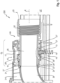
- FIG. 1 A preferred embodiment of a hose coupling system 100 according to the invention is shown in Figure 1
- the hose coupling system 100 is equipped with an inlet fitting 10 and a connector 25.
- the connector 25 has been inserted into the inlet fitting 10 in the coaxial direction R and is supported therein.
- the inlet fitting 10 is arranged on a vacuum cleaner 200, more precisely, it is installed in a housing 210 of the vacuum cleaner. On the left side, the inlet fitting 10 is bounded by a manifold 29 of the vacuum cleaner 200. The manifold 29 leads to a suction turbine (not shown here).
- a suction hose 20 to be connected to the connector 25 is located on the right side of the Figure 1 shown only schematically.
- Such a connecting hose 20 is preferably designed as a spiral-shaped suction hose and is in turn preferably held in a spiral passage 20' formed within the connecting piece 25.
- the hose coupling system 100 has an actuatable locking element 15, by means of which the connecting piece 25 can be held in a form-fitting manner in the inlet fitting 10 and can be released again if necessary.
- the locking element 15 is designed as a spring-loaded retaining bracket 16 with an outer actuating surface 17.
- the spring-loaded retaining bracket 16 will be described later with reference to Figure 5 explained in more detail.
- FIG 1 The locking element 15, designed as a spring-loaded bracket 16, is shown in section.
- Figure 1 the unactuated state UZ, i.e. the compression spring 19 against whose force the locking element 15 is to be actuated, is in the maximally expanded state.
- Figure 1 In the unactuated state UZ shown, the connecting piece 25 is held positively in the inlet fitting 10. This is achieved by the connecting piece 25 having a circumferential locking rim 26 with which the spring-loaded retaining bracket 16 is positively engaged. This positive engagement is in Figure 1 highlighted by an ellipse. In this locked state, the connector 25 cannot be pulled out of the inlet fitting 10 in the coaxial direction R.
- the locking rim 26 has an oblique flank 28 in order to facilitate the locking of the spring-loaded retaining bracket 16 when the connecting piece 25 is inserted into the inlet fitting 10.
- the preferred connector 25 shown further comprises two circumferential support rings 27, 27', which essentially secure the connector 25 in the inlet fitting 10 without play. In other words, these two support rings 27, 27' prevent the connector 25 from rattling within the inlet fitting 10.
- leakage air is minimized by a gap ZR defined between the inclined flank 28 and the inlet fitting 10, since this space essentially represents a labyrinth for any leakage air.
- the connecting piece 25 is held exclusively in a form-fitting manner and in particular free of a conical pairing between the inlet fitting 10 and the connecting piece 25. Due to this cone-free pairing, further design measures are provided in order to minimize unwanted leakage air as much as possible.
- the connecting piece 25 has an annular end face 21 which, when the connecting piece 25 is received and locked in the inlet fitting 10 as shown, rests on a corresponding annular end face 21 of the inlet fitting 10. During suction operation, these corresponding annular end faces 21, 21' are sucked onto one another.
- an annular vertical contact surface is realized.
- the connecting piece 25 has a cylindrical sealing surface 23 which, when the connecting piece 25 is received and engaged in the inlet fitting 10 as shown, rests against a corresponding cylindrical sealing surface 24 of the inlet fitting 10.
- the cylindrical sealing surface 23 has a constant cross-sectional area along a moving cross section in the coaxial direction R.
- at least the cylindrical sealing surface can have a conical shape along the coaxial direction R, for example, to attach a hose with a blowing function.
- the corresponding cylindrical sealing surface 24 of the inlet fitting 10 extends at most over one third of the total length GL of the inlet fitting 10.
- FIG 2 now shows the hose coupling system 100 of the Figure 1 , wherein the locking element 15 designed as a spring-loaded retaining bracket 16 is shown in the actuated state BZ.
- This actuated state BZ is achieved by applying an actuating force F to the outer actuating surface 17 of the spring-loaded retaining bracket 16.
- the actuating force F counteracts a spring force of the compression spring 19.
- a spring-loaded retaining bracket 26 does not necessarily have to be achieved via a compression spring 19.
- leaf springs, disc springs, or the like can be used as spring elements.
- the spring-loaded retaining bracket 16 is brought into the actuated state BZ shown, wherein the locking edge 13 is no longer in engagement with the locking rim 26, or more precisely, is no longer located in the space between the locking rim and the first support ring 27.
- the spring-loaded retaining bracket 16 has a locking edge 13 which is in engagement with the locking rim 16, more precisely in the shown unactuated state OZ is located between the locking rim 26 and the first support ring 27.
- FIG. 3 now shows the preferred connecting piece 25 in detail.
- the connecting piece is cylindrical in shape with respect to the coaxial direction R.
- the locking edge 13 is schematically indicated on the underside. In the unactuated state UZ, this edge is arranged between the locking rim 26 and the first support ring 27, thus preventing the connecting piece 25 10 from being pulled out of the inlet fitting 10 (not shown here) in the coaxial direction.
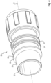
- FIG 4 now shows the connecting piece 25 in perspective.
- the annular end face 21, which serves to seal the connecting piece 25 against the inlet fitting 10, is clearly visible (cf. Figure 1 and 2 ).
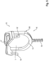
- FIG. 5 Finally, the locking element 15, designed as a spring-loaded retaining bracket 16, is shown in detail.
- the retaining bracket 16 is made in one piece from plastic.
- the retaining bracket 16 has an outer actuating surface 17, which Figure 5 is clearly visible on the upper side. This is partially trough-shaped to facilitate operation with the human finger, or more precisely, to prevent slipping.
- the actuating surface 17 has a surface area of at least 4 cm2 .
- the retaining bracket 16 has a base body GK through which the connecting piece 25 can be pushed at least partially.
- the locking edge 13 In the lower area of the base body GK, opposite the actuating surface 17, is the locking edge 13, which serves to positively lock the connecting piece 25.
- the locking edge 13 does not necessarily have to be designed as a discrete, protruding locking edge, but, as can be seen from the exemplary embodiment shown here, can be part of the base body GK itself.
- the compression spring 19, against whose compressive force the retaining bracket 16 is to be actuated via the actuating surface 17, is clearly visible on the underside of the base body GK.
- the spring-loaded retaining bracket 16 further comprises two retaining lugs 18, 18' to hold the retaining bracket in a housing 210 of the vacuum cleaner 200.
- the connecting piece 25 When the connecting piece 25 is arranged and locked in the inlet fitting 10, the connecting piece 25 is located at least in sections within the lumen L completely enclosed by the base body GK.
- FIG. 6 now shows a perspective view of the hose coupling system 100 installed in a vacuum cleaner housing 210.
- the locking element designed as a spring-loaded retaining bracket 16
- UZ unactuated state
- UZ unactuated state
- UZ unactuated state
- the locking edge 13 of the retaining bracket 16 resting on a surface OF of the connecting piece 25.
- Pulling the connecting piece 25 out of the inlet fitting 10 is not possible in this unactuated state UZ, since the locking edge 13 rests against the locking rim 26.
- Due to the sectional view chosen here the locking rim 26 is not visible, but the first support ring 27 can be seen, which, on the other hand, forms the space between the locking rim 26 and the first support ring.
Landscapes
- Engineering & Computer Science (AREA)
- Mechanical Engineering (AREA)
- General Engineering & Computer Science (AREA)
- Electric Vacuum Cleaner (AREA)
- Quick-Acting Or Multi-Walled Pipe Joints (AREA)
Description
- Die vorliegende Erfindung betrifft ein Schlauchkupplungssystem mit einem Einlass-Fitting und einem Anschlussstück. Das Einlass-Fitting ist an einem Staubsauger anzuordnen oder angeordnet. Das Anschlussstück ist an einen Saugschlauch anzuschließen oder angeschlossen. Das Anschlussstück ist in koaxialer Richtung in das Einlass-Fitting einführbar und in koaxialer Richtung aus dem Einlass-Fitting ausziehbar.
- Schlauchkupplungssysteme der eingangs genannten Art sind grundsätzlich aus dem Stand der Technik bekannt. In der
DE 10 2010 039 282 A wird beispielsweise ein Anschlussstutzen mit Rastelement für einen Staubsauger offenbart, wobei der Anschlussstutzen mit einem Saugschlauch und einer Saugöffnung eines Staubsaugerteils verbindbar ist. - Es ist Aufgabe der vorliegenden Erfindung, ein Schlauchkupplungssystem für einen Staubsauger bereitzustellen, welches ein vergleichsweise einfaches Anschließen des Anschlussstücks am Einlass-Fitting begünstigt.
- Die Aufgabe wird dadurch gelöst, dass das Schlauchkupplungssystem ein betätigbares Rastelement aufweist, mit dem das Anschlussstück formschlüssig im Einlass-Fitting gehalten und bedarfsweise wieder freigegeben werden kann, wobei das Rastelement als federgelagerter Haltebügel ausgebildet ist und der federgelagerte Haltebügel Haltenasen aufweist, um den Haltebügel in einem Gehäuse des Staubsaugers zu halten.
- Die Erfindung schließt die Erkenntnis ein, dass Anschlussstücke für Saugschläuche typischerweise eine Konusform aufweisen, die, zusammenwirkend mit einer korrespondierenden konusförmigen Ausgestaltung des Einlass-Fittings, zu einer Reibpaarung zwischen Anschlussstück und Einlass-Fitting führt. Zwar minimiert eine solche konusförmige Ausgestaltung etwaige Fehlluft in das Einlass-Fitting. Andererseits - dies ist nachteilig - sitzt das konusförmig ausgestaltete Anschlussstück typischerweise vergleichsweise fest innerhalb des Einlass-Fittings. Um nun ein solches Anschlussstück des Standes der Technik aus dem Einlass-Fitting zu entfernen, muss eine vergleichsweise hohe Auszugskraft aufgebracht werden. Neben dem zum Ablösen typischerweise erforderlichen hohen Kraftaufwand ist es nachteiligerweise auch erforderlich, dass das Anschlussstück hinreichend groß ausgebildet werden muss, sodass ein Anwender dieses mit seiner Hand umfassen und herausziehen kann. Problematisch ist neben dem großen bereits erwähnten Kraftaufwand auch der große Platzbedarf im Bereich des Einlass-Fittings des Staubsaugers.
- Durch das erfindungsgemäße Schlauchkupplungssystem können diese Nachteile vermieden werden. Das erfindungsgemäße Schlauchkupplungssystem bietet demnach die Grundlage für eine kompakte Bauweise eines Staubsaugers und eine einfach zu lösende, aber sichere und weitestgehend luftdichte Verbindung.
- In einer besonders bevorzugten Ausgestaltung ist das Anschlussstück bei unbetätigtem Rastelement formschlüssig im Einlass-Fitting gehalten. Das Rastelement ist als federgelagerter Haltebügel ausgebildet, wobei der federgelagerte Haltebügel vorzugsweise eine äußere Betätigungsfläche umfasst. Unter äußerer Betätigungsfläche ist insbesondere eine durch den menschlichen Finger bzw. die menschliche Hand betätigbare Fläche zu verstehen. Vorzugsweise beträgt eine Fläche der äußeren Betätigungsfläche wenigstens 4 cm2.
- In einer bevorzugten Ausgestaltung weist das Anschlussstück eine umlaufende Rastkrempe auf, mit der der federgelagerte Haltebügel, wenn dieser im unbetätigten Zustand befindlich ist, formschlüssig in Eingriff steht. Vorzugsweise umläuft die Rastkrempe das Anschlussstück vollständig. Der federgelagerte Haltebügel weist vorzugsweise eine Rastkante auf, die zum Eingriff mit der Rastkrempe bestimmt ist. Die Rastkante kann unbetätigtem Zustand des federgelagerte Haltebügels Rastkrempe und erstem Stützring befindlich sein.
- Es hat sich als vorteilhaft herausgestellt, wenn der federgelagerte Haltebügel zwei Haltenasen aufweist, um den Haltebügel in einem Gehäuse des Staubsaugers zu halten.
- Besonders bevorzugt weist die Rastkrempe eine schräge Flanke auf, um ein Einrasten des federgelagerten Haltebügels zu erleichtern.
- In einer weiteren bevorzugten Ausgestaltung weist das Anschlussstück wenigstens eine, vorzugsweise zwei umlaufende Stützringe auf, um das Anschlussstück im Wesentlichen spielfrei im Einlass-Fitting auszurichten.
- Es hat sich als vorteilhaft herausgestellt, wenn das Anschlussstück eine Ringstirnfläche aufweist, die, wenn das Anschlussstück in dem Einlass-Fitting aufgenommen und eingerastet ist, auf einer korrespondierenden Ringstirnfläche des Einlass-Fittings aufsteht. Im Saugbetrieb saugen sich die korrespondierenden Ringstirnflächen an und verhindern, zumindest aber minimieren, unerwünschte Fehlluft.
- In einer weiteren bevorzugten Ausgestaltung weist das Anschlussstück eine zylinderförmige Dichtfläche auf, die, wenn das Anschlussstück in dem Einlass-Fitting aufgenommen und eingerastet ist, an einer korrespondierenden, zylinderförmigen Dichtfläche des Einlass-Fittings aufsteht. Vorteilhafterweise minimieren solche korrespondierenden Dichtflächen unerwünschte
- Fehlluft. Zum anderen kann in der zylinderförmigen Dichtfläche bzw. in der dadurch im Einlass-Fitting definierten ringförmigen Öffnung ein weiterer Schlauch, beispielsweise für eine Blasfunktion des Staubsaugers, angeschlossen werden. Es hat sich als vorteilhaft herausgestellt, wenn die korrespondierende, zylinderförmige Dichtfläche des Einlass-Fittings sich höchstens über ein Drittel der Gesamtlänge des Einlass-Fittings erstreckt.
- Es hat sich als vorteilhaft herausgestellt, wenn das Anschlussstück ausschließlich formschlüssig, insbesondere frei von einer konusförmigen Paarung im Einlass-Fitting gehalten wird.
- Die Erfindung führt ebenfalls auf einen Staubsauger mit einem Saugschlauch und einem Schlauchkupplungssystem nach der vorbeschriebenen Art, wobei das Einlass-Fitting an dem Staubsauger angeordnet ist, und das Anschlussstück an dem Saugschlauch angeschlossen ist.
- Weitere Vorteile ergeben sich aus der folgenden Figurenbeschreibung. In den Figuren sind verschiedene Ausführungsbeispiele der vorliegenden Erfindung dargestellt. Die Figuren, die Beschreibung und die Ansprüche enthalten zahlreiche Merkmale in Kombination. Der Fachmann wird die Merkmale zweckmäßigerweise auch einzeln betrachten und zu sinnvollen weiteren Kombinationen zusammenfassen.
- In den Figuren sind gleiche und gleichartige Komponenten mit gleichen Bezugszeichen beziffert. Es zeigen:
- Fig. 1
- einen Schnitt durch ein bevorzugtes Ausführungsbeispiel eines erfindungsgemäßen Schlauchkupplungssystems, das in einem Staubsauger angeordnet ist, wobei ein unbetätigter Zustand des Haltebügels dargestellt ist;
- Fig. 2
- das Ausführungsbeispiel der
Fig. 1 mit betätigtem Haltebügel; - Fig. 3
- das Anschlussstück des vorangehenden Ausführungsbeispiels im Detail;
- Fig. 4
- das Anschlussstück in einer perspektivischen Darstellung;
- Fig. 5
- das als federgelagerter Haltebügel ausgebildete Rastelement des Ausführungsbeispiels der
Figuren 1 und2 ; und - Fig. 6
- eine perspektivische Ansicht eines Schnitts durch ein Schlauchkupplungssystem, wobei das Rastelement in unbetätigtem Zustand ist.
- Ein bevorzugtes Ausführungsbeispiel eines erfindungsgemäßen Schlauchkupplungssystems 100 ist in
Figur 1 dargestellt. Das Schlauchkupplungssystem 100 ist ausgestattet mit einem Einlass-Fitting 10 und einem Anschlussstück 25. Das Anschlussstück 25 wurde in koaxialer Richtung R in das Einlass-Fitting 10 eingeschoben und ist in diesem gelagert. - Das Einlass-Fitting 10 ist an einem Staubsauger 200 angeordnet, genauer gesagt in einem Gehäuse 210 des Staubsaugers eingebaut. Auf der linken Seite ist das Einlass-Fitting 10 durch einen Krümmer 29 des Staubsaugers 200 begrenzt. Der Krümmer 29 führt zu einer hier nicht dargestellten Saugturbine.
- Ein an das Anschlussstück 25 anzuschließender Saugschlauch 20 ist auf der rechten Seite der
Figur 1 lediglich schematisch dargestellt. Ein solcher Anschlussschlauch 20 ist vorzugsweise als spiralförmiger Saugschlauch ausgebildet und wird seinerseits vorzugsweise in einem Spiralgang 20', der innerhalb des Anschlussstücks 25 ausgebildet ist, gehalten. - Erfindungsgemäß weist das Schlauchkupplungssystem 100 ein betätigbares Rastelement 15 auf, mittels dem das Anschlussstück 25 formschlüssig im Einlass-Fitting 10 gehalten und bedarfsweise wieder freigegeben werden kann.
- Im vorliegend dargestellten Ausführungsbeispiel ist das Rastelement 15 als federgelagerter Haltebügel 16 mit einer äußeren Betätigungsfläche 17 ausgebildet. Der federgelagerte Haltebügel 16 wird später mit Bezug auf
Figur 5 genauer erläutert. - In
Figur 1 ist das als federgelagerter Bügel 16 ausgebildete Rastelement 15 im Schnitt dargestellt. Dabei zeigtFigur 1 den unbetätigten Zustand UZ, das heißt die Druckfeder 19 gegen deren Kraft das Rastelement 15 zu betätigen ist, ist in maximal expandiertem Zustand. In dem inFigur 1 gezeigten unbetätigten Zustand UZ wird das Anschlussstück 25 formschlüssig im Einlass-Fitting 10 gehalten. Dies wird dadurch erreicht, dass das Anschlussstück 25 eine umlaufende Rastkrempe 26 aufweist, mit der der federgelagerte Haltebügel 16 formschlüssig in Eingriff steht. Dieser formschlüssige Eingriff ist inFigur 1 durch eine Ellipse hervorgehoben. In diesem eingerasteten Zustand kann das Anschlussstück 25 nicht in koaxialer Richtung R aus dem Einlass-Fitting 10 herausgezogen werden. Gut zu erkennen inFigur 1 ist ebenfalls, dass die Rastkrempe 26 eine schräge Flanke 28 aufweist, um ein Einrasten des federgelagerten Haltebügels 16 im Zuge eines Einschiebens des Anschlussstücks 25 in das Einlass-Fitting 10 zu erleichtern. - Das in
Figur 1 dargestellte bevorzugte Anschlussstück 25 weist weiterhin zwei umlaufende Stützringe 27, 27' auf, die das Anschlussstück 25 im Wesentlichen spielfrei im Einlass-Fitting 10 ausrichten. Mit anderen Worten wird durch diese zwei Stützringe 27, 27' verhindert, dass das Anschlussstück 25 innerhalb des Einlass-Fittings 10 klappert. - Des Weiteren wird durch einen Zwischenraum ZR, der zwischen der schrägen Flanke 28 und dem Einlass-Fitting 10 definiert ist, Fehlluft minimiert, da dieser Raum quasi ein Labyrinth für etwaige Fehlluft darstellt.
- Wie der
Figur 1 entnommen werden kann, ist das Anschlussstück 25 ausschließlich formschlüssig und insbesondere frei von einer konusförmigen Paarung zwischen Einlass-Fitting 10 und Anschlussstück 25 gehalten. Aufgrund dieser konusfreien Paarung sind weitere konstruktive Maßnahmen vorgesehen, um unerwünschte Fehlluft weitest möglich zu minimieren. So weist das Anschlussstück 25 eine Ringstirnfläche 21 auf, die, wenn das Anschlussstück 25 wie gezeigt in dem Einlass-Fitting 10 aufgenommen und eingerastet ist, auf einer korrespondierenden Ringstirnfläche 21 des Einlass-Fittings 10 aufsteht. Im Zuge des Saugbetriebs saugen sich diese korrespondierenden Ringstirnfläche 21, 21' aneinander an. Es wird somit, bezogen auf die koaxiale Richtung R, eine ringförmige senkrechte Kontaktfläche realisiert. - Als weitere konstruktive Maßnahme zur Minimierung der Fehlluft weist das Anschlussstück 25 eine zylinderförmige Dichtfläche 23 auf, die, wenn das Anschlussstück 25 wie gezeigt in dem Einlass-Fitting 10 aufgenommen und eingerastet ist, an einer korrespondierenden, zylinderförmigen Dichtfläche 24 des Einlass-Fittings 10 anliegt. Im dargestellten Ausführungsbeispiel weist die zylinderförmige Dichtfläche 23, entlang eines wandernden Querschnitts in koaxialer Richtung R, eine konstante Querschnittsfläche auf. Alternativ kann zumindest die zylinderförmige Dichtfläche entlang der koaxialen Richtung R einen konusförmigen Verlauf aufweisen, um beispielsweise einen Schlauch mit einer Blasfunktion zu befestigen.
- Wie anhand des in
Figur 1 dargestellten bevorzugten Ausführungsbeispiels gezeigt, erstreckt sich die korrespondierende, zylinderförmige Dichtfläche 24 des Einlass-Fittings 10 höchstens über ein Drittel der Gesamtlänge GL des Einlass-Fittings 10. -
Figur 2 zeigt nun das Schlauchkupplungssystem 100 derFigur 1 , wobei das als federgelagerter Haltebügel 16 ausgebildete Rastelement 15 in betätigtem Zustand BZ dargestellt ist. - Dieser betätigte Zustand BZ wird durch Aufbringen einer Betätigungskraft F auf die äußere Betätigungsfläche 17 des federgelagerten Haltebügels 16 erreicht. Dabei wirkt die Betätigungskraft F einer Federkraft der Druckfeder 19 entgegen. Es sei bemerkt, dass eine Federlagerung des Haltebügels 26 nicht notwendigerweise über eine Druckfeder 19 erreicht werden muss. Alternativ können beispielsweise Blattfedern, Tellerfedern oder dgl. als Federelement verwendet werden.
- Durch die aufgebrachte Betätigungskraft F wird der federgelagerte Haltebügel 16 in den gezeigten betätigten Zustand BZ verbracht, wobei die Rastkante 13 nun nicht mehr im Eingriff mit der Rastkrempe 26 ist, genauer gesagt nicht im Zwischenraum zwischen Rastkrempe und erstem Stützring 27 befindlich ist.
- Wie der
Figur 1 entnommen werden kann, weist der federgelagerte Haltebügel 16 eine Rastkante 13 auf, die in Eingriff mit der Rastkrempe 16 ist, genauer gesagt im gezeigten unbetätigten Zustand OZ zwischen Rastkrempe 26 und erstem Stützring 27 befindlich ist. - In diesem in
Figur 2 gezeigten betätigten Zustand BZ kann das Anschlussstück 25 mühelos in axialer Richtung R aus dem Einlass-Fitting 10 herausgezogen werden. Dies insbesondere auch deshalb, da das Anschlussstück 25 frei von einer konusförmigen Paarung im Einlass-Fitting 10 gehalten wird. -
Figur 3 zeigt nun das bevorzugte Anschlussstück 25 im Detail. Das Anschlussstück ist bezogen auf die koaxiale Richtung R zylinderförmig ausgestaltet. Gut zu erkennen ist die Rastkrempe 26 nebst ihrer Flanke 28, sowie der erste Stützring 27 und der zweite Stützring 27'. Auf der Unterseite schematisch angedeutet ist die Rastkante 13, die, im unbetätigten Zustand UZ, zwischen der Rastkrempe 26 und dem ersten Stützring 27 angeordnet ist, sodass ein Herausziehen des Anschlussstücks 25 10 aus dem hier nicht dargestellten Einlass-Fitting 10 in koaxialer Richtung verhindert wird. -
Figur 4 zeigt nunmehr das Anschlussstück 25 in perspektivischer Darstellung. Gut zu erkennen ist die stirnseitig ausgebildete Ringstirnfläche 21, die einem Abdichten des Anschlussstücks 25 gegenüber dem Einlass-Fitting 10 dient (vgl.Figur 1 und2 ). Gleichfalls gut zu erkennen ist die zylinderförmige Dichtfläche 23, die endständig am Anschlussstück 25 ausgebildet ist und im Zusammenwirken mit der korrespondierenden, zylinderförmigen Dichtfläche 24 des Einlass-Fittings 10 (vgl.Figur 1 und2 ) ebenfalls der Minimierung von Fehlluft dient. -
Figur 5 zeigt schließlich das als federgelagerte Haltebügel 16 ausgebildete Rastelement 15 im Detail. Der Haltebügel 16 ist vorliegend einstückig aus Kunststoff gefertigt. Der Haltebügel 16 weist eine äußere Betätigungsfläche 17 auf, die inFigur 5 auf der Oberseite gut zu erkennen ist. Diese ist teilweise muldenförmig ausgebildet, um eine Bedienung mittels des menschlichen Fingers zu erleichtern, genauer gesagt, um ein Abrutschen zu vermeiden. Die Betätigungsfläche 17 weist im vorliegend dargestellten Ausführungsbeispiel eine Oberfläche von wenigstens 4 cm2 auf. - Der Haltebügel 16 weist einen Grundkörper GK auf, durch den das Anschlussstück 25 zumindest abschnittsweise hindurchgeschoben werden kann. Im unteren Bereich des Grundkörpers GK, der Betätigungsfläche 17 gegenüberliegend, ist die Rastkante 13 angeordnet, die der formschlüssigen Arretierung des Anschlussstücks 25 dient. Es sei bemerkt, dass die Rastkante 13 nicht notwendigerweise als diskrete abstehende Rastkante ausgebildet sein muss, sondern, wie aus dem hier gezeigten Ausführungsbeispiel ersichtlich ist, Teil des Grundkörpers GK selbst sein kann. Auf der Unterseite des Grundkörpers GK ist gut die Druckfeder 19 zu erkennen, gegen deren Druckkraft der Haltebügel 16 über die Betätigungsfläche 17 zu betätigen ist.
- Der federgelagerte Haltebügel 16 weist weiterhin zwei Haltenasen 18, 18' auf, um den Haltebügel in einem Gehäuse 210 des Staubsaugers 200 zu halten.
- Wenn das Anschlussstück 25 im Einlass-Fitting 10 angeordnet und eingerastet ist, befindet sich das Anschlussstück 25 zumindest abschnittsweise innerhalb des durch den Grundkörper GK vollständig umschlossenen Lumens L.
-
Figur 6 zeigt nunmehr, dass in ein Staubsaugergehäuse 210 eingebaute Schlauchkupplungssystem 100 in perspektivischer Darstellung. Das als federgelagerter Haltebügel 16 ausgebildete Rastelement ist in unbetätigtem Zustand UZ, wobei die Rastkante 13 des Haltebügels 16 auf einer Oberfläche OF des Anschlussstücks 25 aufliegt. Ein Herausziehen des Anschlussstücks 25 aus dem Einlass-Fitting 10 ist in diesem unbetätigten Zustand UZ nicht möglich, da die Rastkante 13 gegen die Rastkrempe 26 ansteht. Aufgrund der hier gewählten Schnittdarstellung ist die Rastkrempe 26 nicht erkennbar, wohl aber der erste Stützring 27, der andererseits den Zwischenraum zwischen Rastkrempe 26 und ersten Stützring -
- 10
- Einlass-Fitting
- 13
- Rastkante
- 15
- Rastelement
- 16
- federgelagerten Haltebügel
- 17
- Betätigungsfläche
- 18, 18'
- Haltenase
- 19
- Druckfeder
- 20
- Saugschlauch
- 20'
- Spiralgang
- 21
- Ringstirnfläche
- 22'
- korrespondierende Ringstirnfläche
- 23
- Dichtfläche
- 24
- korrespondierende Dichtfläche
- 25
- Anschlussstück
- 26
- Rastkrempe
- 27, 27'
- Stützringe
- 28
- Flanke
- 29
- Krümmer
- 200
- Staubsauger
- 210
- Gehäuse
- F
- Betätigungskraft
- GL
- Gesamtlänge
- GK
- Grundkörper
- L
- Lumen
- OF
- Oberfläche
- R
- koaxiale Richtung
- BZ
- betätigter Zustand
- UZ
- unbetätigter Zustand
- ZR
- Zwischenraum
Claims (10)
- Schlauchkupplungssystem (100) mit einem Einlass-Fitting (10), das an einem Staubsauger (200) anzuordnen oder angeordnet ist, und mit einem Anschlussstück (25), das an einen Saugschlauch (20) anzuschließen oder angeschlossen ist, wobei das Anschlussstück (25) in koaxialer Richtung (R) in das Einlass-Fitting (10) einzuführen ist,wobei das Schlauchkupplungssystem (100) ein betätigbares Rastelement (15) aufweist, mittels dem das Anschlussstück (25) formschlüssig im Einlass-Fitting (10) gehalten und bedarfsweise wieder freigegeben werden kann,wobei das Rastelement (15) als federgelagerter Haltebügel (16) mit einer äußeren Betätigungsfläche (17) ausgebildet ist,dadurch gekennzeichnet, dassder federgelagerte Haltebügel (16) zwei Haltenasen (18, 18') aufweist um den Haltebügel (16) in einem Gehäuse (210) des Staubsaugers (200) zu halten.
- Schlauchkupplungssystem (100) nach Anspruch 1,
dadurch gekennzeichnet, dass das Anschlussstück (25) bei unbetätigtem Rastelement (15) formschlüssig im Einlass-Fitting (10) gehalten wird. - Schlauchkupplungssystem (100) nach Anspruch 1 oder 2,
dadurch gekennzeichnet, dass das Anschlussstück (25) eine vorzugsweise umlaufende Rastkrempe (26) aufweist mit der der federgelagerte Haltebügel (16), wenn dieser in unbetätigtem Zustand befindlich ist, formschlüssig in Eingriff steht. - Schlauchkupplungssystem (100) nach Anspruch 3,
dadurch gekennzeichnet, dass die Rastkrempe (26) ein schräge Flanke (28) um ein Einrasten des federgelagerten Haltebügels (16) zu erleichtern. - Schlauchkupplungssystem (100) nach einem der vorangehenden Ansprüche,
dadurch gekennzeichnet, dass das Anschlussstück (25) wenigstens eine, vorzugsweise zwei umlaufende Stützringe (27, 27') aufweist, um das Anschlussstück (25) im Wesentlichen spielfrei im Einlass-Fitting (10) auszurichten. - Schlauchkupplungssystem (100) nach einem der vorangehenden Ansprüche,
dadurch gekennzeichnet, dass das Anschlussstück (25) eine Ringstirnfläche (21) aufweist, die, wenn das Anschlussstück (25) in dem Einlass-Fitting (10) aufgenommen und eingerastet ist, auf einer korrespondierenden Ringstirnfläche (21)' des Einlass-Fittings (10) aufsteht. - Schlauchkupplungssystem (100) nach einem der vorangehenden Ansprüche,
dadurch gekennzeichnet, dass das Anschlussstück (25) eine zylinderförmige Dichtfläche (23) aufweist, die, wenn das Anschlussstück (25) in dem Einlass-Fitting (10) aufgenommen und eingerastet ist, an einer korrespondierenden, zylinderförmigen Dichtfläche (24) des Einlass-Fittings (10) aufsteht. - Schlauchkupplungssystem (100) nach Anspruch 3,
dadurch gekennzeichnet, dass sich die korrespondierende, zylinderförmige Dichtfläche (24) des Einlass-Fittings (10) höchstens über ein Drittel der Gesamtlänge (GL) des Einlass-Fittings (10) erstreckt. - Schlauchkupplungssystem (100) nach einem der vorangehenden Ansprüche,
dadurch gekennzeichnet, dass das Anschlussstück (25) ausschließlich formschlüssig, insbesondere frei von einer konusförmigen Paarung im Einlass-Fitting (10) gehalten wird. - Staubsauger (200) mit einem Saugschlauch (20) und einem Schlauchkupplungssystem (100) nach einem der vorangehenden Ansprüche, wobei das Einlass-Fitting (10) an dem Staubsauger (100) angeordnet ist, und das Anschlussstück (25) an dem Saugschlauch (20) angeschlossen ist.
Applications Claiming Priority (2)
| Application Number | Priority Date | Filing Date | Title |
|---|---|---|---|
| EP18163880.0A EP3545808A1 (de) | 2018-03-26 | 2018-03-26 | Schlauchkupplungssystem für einen staubsauger |
| PCT/EP2019/056659 WO2019185382A1 (de) | 2018-03-26 | 2019-03-18 | Schlauchkupplungssystem für einen staubsauger |
Publications (2)
| Publication Number | Publication Date |
|---|---|
| EP3773109A1 EP3773109A1 (de) | 2021-02-17 |
| EP3773109B1 true EP3773109B1 (de) | 2025-06-04 |
Family
ID=61768189
Family Applications (2)
| Application Number | Title | Priority Date | Filing Date |
|---|---|---|---|
| EP18163880.0A Withdrawn EP3545808A1 (de) | 2018-03-26 | 2018-03-26 | Schlauchkupplungssystem für einen staubsauger |
| EP19710424.3A Active EP3773109B1 (de) | 2018-03-26 | 2019-03-18 | Schlauchkupplungssystem für einen staubsauger |
Family Applications Before (1)
| Application Number | Title | Priority Date | Filing Date |
|---|---|---|---|
| EP18163880.0A Withdrawn EP3545808A1 (de) | 2018-03-26 | 2018-03-26 | Schlauchkupplungssystem für einen staubsauger |
Country Status (3)
| Country | Link |
|---|---|
| US (1) | US20210015328A1 (de) |
| EP (2) | EP3545808A1 (de) |
| WO (1) | WO2019185382A1 (de) |
Families Citing this family (3)
| Publication number | Priority date | Publication date | Assignee | Title |
|---|---|---|---|---|
| CA3045082A1 (en) * | 2018-06-04 | 2019-12-04 | Robert Lee Rawls | Hose valve sub-assembly apparatus and method for retractable hose vacuum systems |
| IT202000001555A1 (it) * | 2020-01-28 | 2021-07-28 | New Ermes Europe Srl | Dispositivo adattatore per aspirapolvere elettrico senza filo |
| WO2024068323A1 (de) * | 2022-09-29 | 2024-04-04 | CleanControlling GmbH | Partikelsammelvorrichtung mit sicherungsmittel für übergänge von leitungsabschnitten eines saugluftstroms |
Family Cites Families (12)
| Publication number | Priority date | Publication date | Assignee | Title |
|---|---|---|---|---|
| BE562806A (de) * | 1956-11-29 | |||
| US4220360A (en) * | 1979-03-30 | 1980-09-02 | Jacek Edwin S | Hose coupling |
| US4964189A (en) * | 1989-01-12 | 1990-10-23 | Hako Minuteman, Inc. | Intake seal for tank vacuum cleaner |
| FR2719105B1 (fr) * | 1994-04-21 | 1996-05-31 | Yto | Coupleur rapide pour conduit sous pression à désaccouplement contrôlé. |
| US6115881A (en) * | 1998-08-28 | 2000-09-12 | Emerson Electric Co. | Secure hose locking device |
| GB0105781D0 (en) * | 2001-03-08 | 2001-04-25 | Dyson Ltd | Wand assembly for a vacuum cleaner |
| KR100519966B1 (ko) * | 2003-10-15 | 2005-10-13 | 삼성광주전자 주식회사 | 청소기의 호스 연결장치 및 이를 구비하는 습건식진공청소기 |
| US7159270B2 (en) * | 2005-02-10 | 2007-01-09 | Nationwide Sales & Service, Inc. | Vacuum cleaner adapters and assemblies including the same |
| DE102010039282A1 (de) * | 2010-08-12 | 2012-02-16 | BSH Bosch und Siemens Hausgeräte GmbH | Anschlussstutzen mit Rastelement |
| DE102012216884A1 (de) * | 2012-09-20 | 2014-03-20 | Robert Bosch Gmbh | Absauganschlusssystem |
| CN104685284B (zh) * | 2012-09-28 | 2017-03-15 | 日东工器株式会社 | 具有安全功能的阴型接头 |
| JP6372646B2 (ja) * | 2013-11-26 | 2018-08-15 | ダイセン株式会社 | ソケットおよびそれを有する管継手 |
-
2018
- 2018-03-26 EP EP18163880.0A patent/EP3545808A1/de not_active Withdrawn
-
2019
- 2019-03-18 EP EP19710424.3A patent/EP3773109B1/de active Active
- 2019-03-18 WO PCT/EP2019/056659 patent/WO2019185382A1/de not_active Ceased
- 2019-03-18 US US17/040,110 patent/US20210015328A1/en active Pending
Also Published As
| Publication number | Publication date |
|---|---|
| US20210015328A1 (en) | 2021-01-21 |
| WO2019185382A1 (de) | 2019-10-03 |
| EP3545808A1 (de) | 2019-10-02 |
| EP3773109A1 (de) | 2021-02-17 |
Similar Documents
| Publication | Publication Date | Title |
|---|---|---|
| DE69421403T2 (de) | Eine durch quetschen lösbare schnellkupplung | |
| DE102014106141A1 (de) | Anschlusstülle für ein Schrader-Ventil (amerikanisch) / Presta-Ventil (französisch) | |
| DE1947939A1 (de) | Steckkupplung fuer Schlaeuche,insbesondere Gartenschlaeuche | |
| WO1998025067A1 (de) | Anschlusskörper für flüssigkeitsleitende steckverbindungen | |
| DE4036759A1 (de) | Rohrverbinder aus muffe und einsteckteil, insbesondere fuer kunststoffrohre | |
| DE202011052283U1 (de) | Steckverbindung mit Sicherungselement und Sicherungselement hierfür | |
| WO2002003520A1 (de) | Anschlussarmatur mit elastischem ring als anschlag | |
| DE102020105041B3 (de) | Steckverbinderelement mit Verriegelungseinrichtung | |
| EP1636521B1 (de) | Verbindungseinrichtung für ein rohr oder dgl | |
| DE2822259C2 (de) | Schnellkupplung für rohrförmige Leitungen, insbesondere für Flüssigkeiten | |
| WO1984001902A1 (fr) | Raccord de catheter | |
| EP3773109A1 (de) | Schlauchkupplungssystem für einen staubsauger | |
| DE1475706A1 (de) | Rohrfoermiges Verbindungsaggregat | |
| EP0587131A1 (de) | Einsteckkupplung für die Verbindung von zwei Kunststoffrohren | |
| DE102010039282A1 (de) | Anschlussstutzen mit Rastelement | |
| EP0280180A2 (de) | Lösbare Steckverbindung für Rohrleitungen | |
| EP2998634A1 (de) | Schlauchanschlussvorrichtung | |
| DE2149136A1 (de) | Schlauch- und Rohrverbinder fuer Schlaeuche und Rohre aus verformbarem Werkstoff | |
| EP0640358B1 (de) | Schlauchkupplung | |
| DE19936413C1 (de) | Schlauchanschluß | |
| DE8619671U1 (de) | Kupplung zum Anschließen eines medizinischen Schlauches, insbesondere eines Drains oder eines Katheters, an eine weitere Einrichtung | |
| DE3623367C2 (de) | ||
| DE10203600B4 (de) | Leckageanschluss zum Anbringen einer Leckageleitung an einen Kraftstoffinjektor | |
| DE202004015244U1 (de) | Schlauchnippel und Schlauchverbindungsmittel | |
| DE10300672B3 (de) | Rohr oder Schlauch mit einer Einschubdrosselhülse sowie Verfahren zur Montage eines Rohres oder Schlauches mit einer Einschubdrosselhülse |
Legal Events
| Date | Code | Title | Description |
|---|---|---|---|
| STAA | Information on the status of an ep patent application or granted ep patent |
Free format text: STATUS: UNKNOWN |
|
| STAA | Information on the status of an ep patent application or granted ep patent |
Free format text: STATUS: THE INTERNATIONAL PUBLICATION HAS BEEN MADE |
|
| PUAI | Public reference made under article 153(3) epc to a published international application that has entered the european phase |
Free format text: ORIGINAL CODE: 0009012 |
|
| STAA | Information on the status of an ep patent application or granted ep patent |
Free format text: STATUS: REQUEST FOR EXAMINATION WAS MADE |
|
| 17P | Request for examination filed |
Effective date: 20201026 |
|
| AK | Designated contracting states |
Kind code of ref document: A1 Designated state(s): AL AT BE BG CH CY CZ DE DK EE ES FI FR GB GR HR HU IE IS IT LI LT LU LV MC MK MT NL NO PL PT RO RS SE SI SK SM TR |
|
| AX | Request for extension of the european patent |
Extension state: BA ME |
|
| DAV | Request for validation of the european patent (deleted) | ||
| DAX | Request for extension of the european patent (deleted) | ||
| STAA | Information on the status of an ep patent application or granted ep patent |
Free format text: STATUS: EXAMINATION IS IN PROGRESS |
|
| 17Q | First examination report despatched |
Effective date: 20240328 |
|
| GRAP | Despatch of communication of intention to grant a patent |
Free format text: ORIGINAL CODE: EPIDOSNIGR1 |
|
| STAA | Information on the status of an ep patent application or granted ep patent |
Free format text: STATUS: GRANT OF PATENT IS INTENDED |
|
| INTG | Intention to grant announced |
Effective date: 20250218 |
|
| GRAS | Grant fee paid |
Free format text: ORIGINAL CODE: EPIDOSNIGR3 |
|
| GRAA | (expected) grant |
Free format text: ORIGINAL CODE: 0009210 |
|
| STAA | Information on the status of an ep patent application or granted ep patent |
Free format text: STATUS: THE PATENT HAS BEEN GRANTED |
|
| AK | Designated contracting states |
Kind code of ref document: B1 Designated state(s): AL AT BE BG CH CY CZ DE DK EE ES FI FR GB GR HR HU IE IS IT LI LT LU LV MC MK MT NL NO PL PT RO RS SE SI SK SM TR |
|
| REG | Reference to a national code |
Ref country code: GB Ref legal event code: FG4D Free format text: NOT ENGLISH |
|
| REG | Reference to a national code |
Ref country code: CH Ref legal event code: EP |
|
| REG | Reference to a national code |
Ref country code: DE Ref legal event code: R096 Ref document number: 502019013403 Country of ref document: DE |
|
| REG | Reference to a national code |
Ref country code: IE Ref legal event code: FG4D Free format text: LANGUAGE OF EP DOCUMENT: GERMAN |
|
| P01 | Opt-out of the competence of the unified patent court (upc) registered |
Free format text: CASE NUMBER: UPC_APP_2306_3773109/2025 Effective date: 20250804 |
|
| REG | Reference to a national code |
Ref country code: NL Ref legal event code: MP Effective date: 20250604 |
|
| PG25 | Lapsed in a contracting state [announced via postgrant information from national office to epo] |
Ref country code: FI Free format text: LAPSE BECAUSE OF FAILURE TO SUBMIT A TRANSLATION OF THE DESCRIPTION OR TO PAY THE FEE WITHIN THE PRESCRIBED TIME-LIMIT Effective date: 20250604 Ref country code: ES Free format text: LAPSE BECAUSE OF FAILURE TO SUBMIT A TRANSLATION OF THE DESCRIPTION OR TO PAY THE FEE WITHIN THE PRESCRIBED TIME-LIMIT Effective date: 20250604 |
|
| REG | Reference to a national code |
Ref country code: LT Ref legal event code: MG9D |
|
| PG25 | Lapsed in a contracting state [announced via postgrant information from national office to epo] |
Ref country code: GR Free format text: LAPSE BECAUSE OF FAILURE TO SUBMIT A TRANSLATION OF THE DESCRIPTION OR TO PAY THE FEE WITHIN THE PRESCRIBED TIME-LIMIT Effective date: 20250905 Ref country code: NO Free format text: LAPSE BECAUSE OF FAILURE TO SUBMIT A TRANSLATION OF THE DESCRIPTION OR TO PAY THE FEE WITHIN THE PRESCRIBED TIME-LIMIT Effective date: 20250904 |
|
| PG25 | Lapsed in a contracting state [announced via postgrant information from national office to epo] |
Ref country code: PL Free format text: LAPSE BECAUSE OF FAILURE TO SUBMIT A TRANSLATION OF THE DESCRIPTION OR TO PAY THE FEE WITHIN THE PRESCRIBED TIME-LIMIT Effective date: 20250604 |
|
| PG25 | Lapsed in a contracting state [announced via postgrant information from national office to epo] |
Ref country code: BG Free format text: LAPSE BECAUSE OF FAILURE TO SUBMIT A TRANSLATION OF THE DESCRIPTION OR TO PAY THE FEE WITHIN THE PRESCRIBED TIME-LIMIT Effective date: 20250604 |
|
| PG25 | Lapsed in a contracting state [announced via postgrant information from national office to epo] |
Ref country code: HR Free format text: LAPSE BECAUSE OF FAILURE TO SUBMIT A TRANSLATION OF THE DESCRIPTION OR TO PAY THE FEE WITHIN THE PRESCRIBED TIME-LIMIT Effective date: 20250604 |
|
| PG25 | Lapsed in a contracting state [announced via postgrant information from national office to epo] |
Ref country code: RS Free format text: LAPSE BECAUSE OF FAILURE TO SUBMIT A TRANSLATION OF THE DESCRIPTION OR TO PAY THE FEE WITHIN THE PRESCRIBED TIME-LIMIT Effective date: 20250904 |
|
| PG25 | Lapsed in a contracting state [announced via postgrant information from national office to epo] |
Ref country code: LV Free format text: LAPSE BECAUSE OF FAILURE TO SUBMIT A TRANSLATION OF THE DESCRIPTION OR TO PAY THE FEE WITHIN THE PRESCRIBED TIME-LIMIT Effective date: 20250604 |
|
| PG25 | Lapsed in a contracting state [announced via postgrant information from national office to epo] |
Ref country code: NL Free format text: LAPSE BECAUSE OF FAILURE TO SUBMIT A TRANSLATION OF THE DESCRIPTION OR TO PAY THE FEE WITHIN THE PRESCRIBED TIME-LIMIT Effective date: 20250604 |
|
| PG25 | Lapsed in a contracting state [announced via postgrant information from national office to epo] |
Ref country code: PT Free format text: LAPSE BECAUSE OF FAILURE TO SUBMIT A TRANSLATION OF THE DESCRIPTION OR TO PAY THE FEE WITHIN THE PRESCRIBED TIME-LIMIT Effective date: 20251006 |
|
| PG25 | Lapsed in a contracting state [announced via postgrant information from national office to epo] |
Ref country code: IS Free format text: LAPSE BECAUSE OF FAILURE TO SUBMIT A TRANSLATION OF THE DESCRIPTION OR TO PAY THE FEE WITHIN THE PRESCRIBED TIME-LIMIT Effective date: 20251004 |
|
| PG25 | Lapsed in a contracting state [announced via postgrant information from national office to epo] |
Ref country code: SM Free format text: LAPSE BECAUSE OF FAILURE TO SUBMIT A TRANSLATION OF THE DESCRIPTION OR TO PAY THE FEE WITHIN THE PRESCRIBED TIME-LIMIT Effective date: 20250604 |
|
| PG25 | Lapsed in a contracting state [announced via postgrant information from national office to epo] |
Ref country code: CZ Free format text: LAPSE BECAUSE OF FAILURE TO SUBMIT A TRANSLATION OF THE DESCRIPTION OR TO PAY THE FEE WITHIN THE PRESCRIBED TIME-LIMIT Effective date: 20250604 |
|
| PG25 | Lapsed in a contracting state [announced via postgrant information from national office to epo] |
Ref country code: EE Free format text: LAPSE BECAUSE OF FAILURE TO SUBMIT A TRANSLATION OF THE DESCRIPTION OR TO PAY THE FEE WITHIN THE PRESCRIBED TIME-LIMIT Effective date: 20250604 |
|
| PG25 | Lapsed in a contracting state [announced via postgrant information from national office to epo] |
Ref country code: RO Free format text: LAPSE BECAUSE OF FAILURE TO SUBMIT A TRANSLATION OF THE DESCRIPTION OR TO PAY THE FEE WITHIN THE PRESCRIBED TIME-LIMIT Effective date: 20250604 Ref country code: SK Free format text: LAPSE BECAUSE OF FAILURE TO SUBMIT A TRANSLATION OF THE DESCRIPTION OR TO PAY THE FEE WITHIN THE PRESCRIBED TIME-LIMIT Effective date: 20250604 |
|
| PG25 | Lapsed in a contracting state [announced via postgrant information from national office to epo] |
Ref country code: IT Free format text: LAPSE BECAUSE OF FAILURE TO SUBMIT A TRANSLATION OF THE DESCRIPTION OR TO PAY THE FEE WITHIN THE PRESCRIBED TIME-LIMIT Effective date: 20250604 |
|
| REG | Reference to a national code |
Ref country code: DE Ref legal event code: R097 Ref document number: 502019013403 Country of ref document: DE |
|
| PLBE | No opposition filed within time limit |
Free format text: ORIGINAL CODE: 0009261 |
|
| STAA | Information on the status of an ep patent application or granted ep patent |
Free format text: STATUS: NO OPPOSITION FILED WITHIN TIME LIMIT |
|
| PG25 | Lapsed in a contracting state [announced via postgrant information from national office to epo] |
Ref country code: DK Free format text: LAPSE BECAUSE OF FAILURE TO SUBMIT A TRANSLATION OF THE DESCRIPTION OR TO PAY THE FEE WITHIN THE PRESCRIBED TIME-LIMIT Effective date: 20250604 |
|
| PGFP | Annual fee paid to national office [announced via postgrant information from national office to epo] |
Ref country code: DE Payment date: 20260319 Year of fee payment: 8 |
|
| REG | Reference to a national code |
Ref country code: CH Ref legal event code: L10 Free format text: ST27 STATUS EVENT CODE: U-0-0-L10-L00 (AS PROVIDED BY THE NATIONAL OFFICE) Effective date: 20260416 |
|
| 26N | No opposition filed |
Effective date: 20260305 |