EP3773257B1 - Dispositif de compression gonflable - Google Patents
Dispositif de compression gonflable Download PDFInfo
- Publication number
- EP3773257B1 EP3773257B1 EP19784978.9A EP19784978A EP3773257B1 EP 3773257 B1 EP3773257 B1 EP 3773257B1 EP 19784978 A EP19784978 A EP 19784978A EP 3773257 B1 EP3773257 B1 EP 3773257B1
- Authority
- EP
- European Patent Office
- Prior art keywords
- bladder
- top plate
- indicium
- location
- hemostasis device
- Prior art date
- Legal status (The legal status is an assumption and is not a legal conclusion. Google has not performed a legal analysis and makes no representation as to the accuracy of the status listed.)
- Active
Links
Images


Classifications
-
- A—HUMAN NECESSITIES
- A61—MEDICAL OR VETERINARY SCIENCE; HYGIENE
- A61B—DIAGNOSIS; SURGERY; IDENTIFICATION
- A61B17/00—Surgical instruments, devices or methods
- A61B17/12—Surgical instruments, devices or methods for ligaturing or otherwise compressing tubular parts of the body, e.g. blood vessels or umbilical cord
- A61B17/132—Tourniquets
- A61B17/135—Tourniquets inflatable
-
- A—HUMAN NECESSITIES
- A61—MEDICAL OR VETERINARY SCIENCE; HYGIENE
- A61B—DIAGNOSIS; SURGERY; IDENTIFICATION
- A61B17/00—Surgical instruments, devices or methods
- A61B17/12—Surgical instruments, devices or methods for ligaturing or otherwise compressing tubular parts of the body, e.g. blood vessels or umbilical cord
- A61B17/132—Tourniquets
- A61B17/1322—Tourniquets comprising a flexible encircling member
- A61B17/1325—Tourniquets comprising a flexible encircling member with means for applying local pressure
-
- A—HUMAN NECESSITIES
- A61—MEDICAL OR VETERINARY SCIENCE; HYGIENE
- A61B—DIAGNOSIS; SURGERY; IDENTIFICATION
- A61B17/00—Surgical instruments, devices or methods
- A61B2017/00831—Material properties
- A61B2017/00902—Material properties transparent or translucent
- A61B2017/00907—Material properties transparent or translucent for light
-
- A—HUMAN NECESSITIES
- A61—MEDICAL OR VETERINARY SCIENCE; HYGIENE
- A61B—DIAGNOSIS; SURGERY; IDENTIFICATION
- A61B17/00—Surgical instruments, devices or methods
- A61B17/12—Surgical instruments, devices or methods for ligaturing or otherwise compressing tubular parts of the body, e.g. blood vessels or umbilical cord
- A61B2017/12004—Surgical instruments, devices or methods for ligaturing or otherwise compressing tubular parts of the body, e.g. blood vessels or umbilical cord for haemostasis, for prevention of bleeding
-
- A—HUMAN NECESSITIES
- A61—MEDICAL OR VETERINARY SCIENCE; HYGIENE
- A61B—DIAGNOSIS; SURGERY; IDENTIFICATION
- A61B90/00—Instruments, implements or accessories specially adapted for surgery or diagnosis and not covered by any of the groups A61B1/00 - A61B50/00, e.g. for luxation treatment or for protecting wound edges
- A61B90/08—Accessories or related features not otherwise provided for
- A61B2090/0807—Indication means
-
- A—HUMAN NECESSITIES
- A61—MEDICAL OR VETERINARY SCIENCE; HYGIENE
- A61B—DIAGNOSIS; SURGERY; IDENTIFICATION
- A61B90/00—Instruments, implements or accessories specially adapted for surgery or diagnosis and not covered by any of the groups A61B1/00 - A61B50/00, e.g. for luxation treatment or for protecting wound edges
- A61B90/39—Markers, e.g. radio-opaque or breast lesions markers
- A61B2090/3937—Visible markers
Definitions
- the present disclosure relates generally to the field of medical devices used to provide hemostasis at a vascular access puncture site. More particularly, some embodiments of the present disclosure relate to inflatable hemostasis devices used to provide hemostasis of the arteries of the wrist, hand and foot, including the distal radial artery, following vascular access. Alignment indicia associated with inflatable hemostasis devices and the use thereof are also disclosed herein.
- the document US 2015/327871 A1 describes a device for targeting force applied to a radial access puncture site, comprising a cuff, an inflatable balloon disposed over the radial access puncture site, and targeting indicia disposed on the inflatable balloon or a rigid or semi-rigid member.
- the document US 2012/238934 A1 describes a compression system for compression against a puncture site of a vessel in a patient, comprising a compression element, a tightening unit, the compression element being provided with a placement mark indicating where the compression element should be placed.
- the document US 2018/014832 A1 describes a radial artery compression device, comprising a partially transparent rigid frame, a partially transparent and flexible sheet that is coupled to the frame, and an inflatable chamber.
- medical procedures involve insertion of one or more elongate medical devices into the vasculature of a patient. Achieving hemostasis during and/or after an interventional procedure that involves puncturing an artery may present certain challenges.
- pressure may be applied at or slightly upstream of the skin puncture site. Such pressure may prevent or reduce the leakage of blood from the arteriotomy site and promote hemostasis.
- the compression may be applied by a healthcare worker or by a hemostasis device, such as the hemostasis devices described herein.
- hemostasis devices may comprise bands for securement of the device to a patient and a compression member to apply a pressure or compressive force to the puncture site.
- a method for applying compression to a puncture site is through an inflatable hemostasis device.
- An inflatable hemostasis device may comprise a transparent portion to facilitate alignment of the device and/or visual assessment of hemostasis.
- An inflatable hemostasis device may also comprise alignment indicia to facilitate alignment of an inflatable bladder over the puncture site. Depending on the location of the alignment indicia on the device, the effects of parallax may affect the ability of the practitioner to properly align the inflatable hemostasis device over the puncture site.
- the inflatable hemostasis device may be configured to reduce or limit the effects of parallax.
- Coupled to is broad enough to refer to any suitable coupling or other form of interaction between two or more entities, including mechanical and fluidic. Thus, two components may be coupled to each other even though they are not in direct contact with each other.
- fluid communication is used in its ordinary sense, and is broad enough to refer to arrangements in which a fluid (e.g., a gas or a liquid) can flow from one element to another element when the elements are in fluid communication with each other.
- proximal and distal are opposite directional terms.
- distal end of a device or component is the end of the component that is furthest from the practitioner during ordinary use.
- proximal end refers to the opposite end, or the end nearest the practitioner during ordinary use.
- fluid is used in its broadest sense, to refer to any fluid, including both liquids and gases as well as solutions, compounds, suspensions, etc., which generally behave as fluids.
- compression is used to define a compressive force or pressure applied to a portion of patient over a specific area.
- the compression level may correlate to a pressure within an inflatable component of the device.
- the compression level may also correlate to a volumetric size or shape of an inflatable component.
- inflation is defined as a volumetric condition of an expandable sealed container.
- An increase of inflation is analogous to an increase in fluid content with the container or to the volumetric size of an expandable container.
- the inflation fluid may be compressible or non-compressible.
- the inflation level may be may or may not be analogous to an internal pressure.
- FIG. 1 provides a top view of an embodiment of an inflatable hemostasis device 100.
- the hemostasis device 100 may comprise a compression member 110 and a securement system 120.
- the securement system 120 may be coupled to the compression member 110 and be configured to facilitate a secure attachment of the compression member 110 over a puncture site.
- the hemostasis device 100 may be configured to provide compression to various locations on a patient and the securement system may be configured to secure the hemostasis device 100 to various portions of a patient's body such as a wrist, hand or foot.
- the securement system 120 may comprise bands that wrap around a portion of the patient's body. There may be one, two, three, four or more bands.
- the bands may comprise any suitable releasable securement mechanism, such as a hook-and-loop material, pressure sensitive adhesives, buckles, magnets, snaps, clasps, etc. all of which are contemplated to be within the scope of this disclosure.
- the securement system 120 may be configured to provide lateral and longitudinal positional stability of the compression member 110 over a puncture site.
- the hemostasis device 100 may comprise a compression member 110.
- the compression member 110 is specifically configured to provide compression to the snuff box of the left hand.
- the compression member 110 as described herein, may be considered generic. Said another way, the compression member 110 may be configured to provide compression to various locations on a patient such as a wrist, hand or foot.
- the compression member 110 may be configured to provide compression over a specifically defined area of a patient.
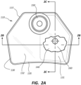
- the compression member 110 may comprise a perimeter 115 of FIG. 2A having a plurality of sides. There may be three, four, five, six or more sides. The sides may be straight, concave or convex. The sides may be configured to facilitate coupling of the securement system 120 to any number of sides.
- the compression member 110 may comprise a symmetrical or non-symmetrical shape. The shape may be configured to correlate with the anatomy of a patient adjacent a puncture site. The shape may also facilitate proper alignment and placement of the hemostasis device 100. Still again, the shape may facilitate desired aesthetic properties of the hemostasis device 100.
- the compression member 110 may comprise components that are transparent or translucent.
- FIG. 2A shows the compression member 110 having properties, features and characteristics consistent with the hemostasis device 100.
- FIG. 2A shows the compression member 110 having properties, features and characteristics consistent with the hemostasis device 100.
- certain properties, features, and characteristics described herein are generic in nature and may apply to hemostasis devices configured to provide compression to any location on a patient and for any therapy where compression is beneficial.
- the compression member 110 may comprise a top plate 130, a bladder 140, an inflation port 150, and a location indicium 160.
- the bladder 140 may be disposed on the bottom of the compression member 110 so as to be disposed adjacent the skin of a patient and provide compression to a puncture site.
- the bladder 140 may be coupled to the top plate 130 and in fluid communication with the inflation port 150.
- the location indicium 160 may be disposed at any suitable location on the compression member 110.
- the top plate 130 may be configured to convert tension in the securement system 120 to a downward force on the patient.
- the top plate 130 may be configured to provide a support for the bladder 140.
- the top plate 130 may be flexible or semi-flexible so as to conform to the anatomy of a patient upon securement.
- the top plate 130 may also be rigid.
- the top plate 130 may comprise a substantially flat plate, and/or may comprise flat, curved, convex or concave portions. Further, the top plate 130 may be symmetrical or non-symmetrical.
- the top plate 130 is coupled to the securement system 120.
- the top plate 130 may comprise a perimeter 135 having a plurality of sides. There may be three, four, five, six or more sides.
- the sides may be straight, concave or convex.
- the sides may be configured to facilitate coupling of the securement system 120 to any number of sides.
- the top plate 130 may comprise at least one of a hole, slot, protrusion, etc. to facilitate coupling to the securement system 120.
- the top plate 130 may be configured to be anatomically compatible with a patient, such as avoiding uncomfortable contact points.
- the top plate 130 may also be configured to provide some level of compression without inflation of the bladder 140 such as comprising a convex portion on the bottom side thereof.
- the top plate 130 may comprise a compression portion 131 disposed above the bladder 140 and a non-compression portion 132.
- the compression portion 131 may comprise the entire top plate 130.
- the non-compression portion 132 may comprise a viewing window through which a practitioner may visually observe at least a portion of the puncture site.
- a bottom surface of the top plate 130 may comprise features such as protrusions, surface displacements, variations in thickness, position or alignment indicators, surface texturing, etc. to facilitate welding or bonding of the bladder 140 to the top plate 130.
- a top surface of the top plate 130 may comprise features such as protrusions, surface displacements, variations in thickness, position or alignment indicators, surface texturing, etc. to facilitate welding or bonding of the inflation port 150 to the top plate 130.
- the top plate 130 may comprise an orifice 190 extending through the top plate 130.
- the top plate 130 may be transparent or translucent such that the puncture site can be seen through the top plate 130 to facilitate alignment of the compression member 110 with the puncture site and assessment of hemostasis during treatment.
- the top plate 130 may be formed of any suitable flexible or semi-flexible material such as polyethylene, polypropylene, polyvinyl chloride, polyurethane, etc. or any suitable rigid material, such as polycarbonate, polystyrene, styrene copolymers, polyethylene terephthalate, acrylic, polyethylene, polypropylene, etc.
- the bladder 140 may be configured to extend downward from the top plate 130 upon inflation.
- the bladder 140 may be disposed on the bottom surface of the top plate 130 such that the top plate 130 prevents upward expansion of the bladder 140.
- the bladder 140 may be configured to be in contact with a patient's skin and provide compression to a puncture site of a patient.
- the bladder 140 may be configured to contain a fluid and maintain an internal fluid pressure.
- the bladder 140 may be configured so that an internal fluid pressure within the bladder 140 and the compressive pressure applied to a patient over a specified area are equal or substantially equal.
- the bladder 140 may be configured to be inflatable and deflatable.
- the bladder 140 may be configured to provide compression to a puncture site over a predefined area or shape.
- the bladder may be configured to provide a predefined compression depth profile.
- the compression area on a patient may be relatively large or small and the compression profile may be relatively deep or shallow defining a range of volumetric capacities for the bladder 140.
- the maximum capacity of the bladder 140 may be between 3 mL and 12 mL, between 3 mL and 20 mL, or between 3 mL and 25 mL. In another embodiment, the maximum capacity may be between 5 mL and 15 mL, between 10 mL and 20 mL, between 10 mL and 30 mL, or between 15 mL and 30 mL.
- the bladder 140 may comprise a flat sheet or a preformed 3-dimensional shape.
- the bladder 140 may be flexible and non-stretchable or flexible and stretchable.
- the bladder 140 may be transparent or translucent to facilitate visible observation of a puncture site.
- the bladder 140 may be coupled to the top plate 130.
- the bladder 140 may be sealably coupled to the top plate 130 along a perimeter of the bladder 140 such that a portion of the top plate 120 forms a top wall of the bladder 140.
- the orifice 190 may be deposed within the perimeter of the bladder 140.
- the bladder 140 may be configured to define specific compression characteristics. Such characteristics may comprise the area, depth, and shape of the compression on a patient.
- FIGS. 2B and 2C show orthogonal cross-sectional views of the compression member 110 with cut lines through an apex 170 of the bladder 140 when the bladder 140 is inflated.
- the apex 170 is defined as the point on the bladder 140 most distant from the top plate 120 when the bladder 140 is inflated.
- the bladder 140 when inflated, defines a compression profile or volumetric shape. When inflated there may be an apex 170 of the bladder 140.
- the location of the apex 170 may be centered within the perimeter of the bladder 140.
- the location of the apex 170 may be offset from the center of the bladder 140.
- the location of the apex 170 may be predetermined by the characteristics of a preform of the bladder 140. Such characteristics may comprise thickness variation and/or three-dimensional shape.
- the bladder 140 may comprise a thick portion to facilitate a relatively flat or uniform compression area on a patient.
- the bladder 140 may comprise preformed folds, such as a bellows arrangement, to facilitate a predefined compression depth and/or profile.
- the preform of the bladder 140 may also facilitate the manufacturing processes of the compression member 110, e.g. printing of an indicium 160 on an inner surface of the bladder 140.
- the preform of the bladder 140 may also facilitate a desired position of the indicium 160 relative to a perimeter of the top plate 130 when the bladder 140 is in an uninflated state.
- the bladder 140 may be formed from any suitable, flexible, transparent or translucent material, such as polyethylene, polypropylene, polyurethane, etc.
- the inflation port 150 may be in fluid communication with the bladder 140.
- the inflation port 150 may be coupled to the top plate 130 such that the inflation port 150 is in fluid communication with the orifice 190.
- fluid communication between the inflation port 150 and the bladder 140 may comprise the orifice 190.
- the inflation port 150 may be disposed toward an outer perimeter of the bladder 140 such that the inflation port 150 does not obstruct visualization of the puncture site.
- the inflation port 150 may be disposed on a line bisecting the top plate 130.
- FIGS. 2A-2C show the inflation port 150 oriented perpendicular to the top plate 130. However, the inflation port 150 may be coupled at any angle relative to an axis perpendicular to the top plate 130.
- the inflation port 150 may comprise a valve to provide for inflation and deflation of the bladder 140 and containment of fluid pressure within the bladder 140.
- the inflation port 150 may be configured to be releasably coupleable to a fluid displacement device, such as a syringe.
- FIG. 3 shows several potential embodiments of patterns for the location indicium 160.
- the illustration of FIG. 3 is non-inclusive and any and all other indicia comprising dots, line segments, curves, circles, polygons, contour lines, arrows, crosses, etc. and any combination thereof that may be configured for alignment purposes are within the scope of this disclosure.
- the location indicium 160 may comprise a point component so as to facilitate two-dimensional alignment of the compression member 110 on the puncture site.
- the indicium 160 may comprise at least one linear component to facilitate rotational alignment with a linear aspect of the patient such as an artery. Additionally or alternatively, the indicium 160 may comprise at least one directional component such as an arrow.
- the directional component may be used to rotationally align the compression member 110 with a specific directional aspect of a patient such as blood flow direction through an artery.
- the location indicium 160 may comprise one, two or all three components of alignment as described above. Additional location indicia may also be disposed on the compression member 110 and may comprise one, two or all three components of alignment as described above.
- the location indicium 160 may also indicate an area, shape and/or depth profile of the compression applied to the patient.
- the location indicium 160 may also comprise contour lines or other components to indicate a concentric or non-concentric depth profile.
- the location indicium 160 may comprise a sequence of two or more components.
- the sequence may define one or more predetermined distances or lengths, such as graduation marks.
- the sequence of two or more components may correlate with multiple point locations on a patient, such as a skin puncture site and an arteriotomy site.
- the location indicium 160 may be disposed on the bladder 140. In some embodiments, the location indicium 160 may be disposed on an inner surface of the bladder 140 as shown in FIGS. 2B and 2C . Disposition of the location indicium 160 on the inner surface of the bladder 140 may provide protection from being inadvertently removed or otherwise damaged through physical contact and/or chemical contact, e.g. with cleaning agents. The patient may also be protected from contact with the location indicium 160 such as printing chemicals, surface roughness, etc.
- the location indicium 160 may be disposed adjacent a center location of the bladder 140.
- the location indicium 160 may be disposed adjacent the apex 170 of the bladder 140.
- the location indicium 160 may be disposed a distance O offset from the center and/or the apex 170 of the bladder 140 as shown in FIG. 2C .
- the offset distance may correlate to the distance between the skin puncture site and the arteriotomy site or may correlate to other marks on a patient's skin.
- Alignment of the compression member 110 with the puncture site on a patient may facilitate hemostasis. Alignment may be facilitated by viewing the puncture site through a transparent or translucent top plate 130 and/or bladder 140. Alignment may be further facilitated by visually aligning the location indicium 160 with the puncture site. In some instances, aligning the location indicium 160 disposed on the compression member 110 with a puncture site on a patient may need to take into account parallax.
- FIG. 4 illustrates the effects of parallax as may be applicable to inflatable hemostasis devices.
- a location indicium LI is shown disposed a height H above the skin surface S of a patient.
- a normal viewing position V1 i.e. normal to a top plate TP, defines a projected indicium location P1 on the skin surface S.
- the location indicium LI may also be disposed at a significant height H above the skin surface S. These two factors may result in misalignment of the indicium LI relative to a puncture site on a patient even when alignment may visually appear to be correct. For example, an angular difference ⁇ of 45 degrees and a height H of 3 mm may combine to produce a distance D approaching 3 mm between the two projected indicium locations P1, P2 on the skin S. In some instances, a miss-alignment distance may cause insufficient compression to a puncture site. Hence, a reduction in the parallax effect may facilitate compression of a puncture site.
- an included angle ⁇ of 45 degrees between two viewing positions V1, V2 and a height H of 3 mm may combine to produce a distance D approaching 3 mm between two projected indicium locations P1, P2 on the skin S when neither of the viewing angles are normal to the top plate TP.
- the inflatable hemostasis device 100 may be configured to limit the parallax effect (distance D).
- compression member 110 may be configured to limit the parallax distance D as described above for a viewing angle ⁇ of 45 degrees to 5, 4, 3, 2, 1, 0.5, 0.25 mm or less.
- the parallax effect may be reduced by reducing the height H. In certain instances reducing the height H by disposition of the location indicium 160 on the inner surface of the bladder 140 may reduce the parallax effect.
- the bladder 140 may be adjacent to or in direct contact with the patient's skin when inflated, thereby positioning the location indicium adjacent the skin. Disposition of the location indicium 160 on the inner surface of the bladder 140, may limit the parallax effect D to be equivalent to the thickness of the bladder 140 when viewed from a 45 degree viewing angle.
- the bladder 140 may be partially inflated or otherwise configured to be significantly close to or in contact with the skin of the patient upon initial placement of the compression member 110 on the patient.
- the top plate 130 and/or bladder 140 may be configured to dispose the bladder 140 close to or in contact with the skin of the patient when uninflated.
- FIG. 2D shows an exploded view of the compression member 110.
- a manufacturing process of the compression member 110 may comprise sealably coupling the inflation port 150 to the top surface of the top plate 130 and sealably coupling the bladder 140 along the perimeter thereof to the bottom surface of the top plate 130.
- Methods of coupling inflation port 150 to the top surface of the top plate 130 and the bladder 140 to the bottom surface of the top plate 130 may comprise ultra-sonic welding, radio frequency welding, solvent bonding, boding with adhesives, etc.
- the manufacturing process may also comprise placement of the location indicium 160 on the inner surface of the bladder 140 prior to coupling the bladder 140 to the top plate 130.
- the process of placing the location indicium 160 on the bladder 140 may comprise altering the visible properties of the bladder 140 during or after the forming process of the bladder 140 which altering may comprise the forming of protrusions or recesses, surface texturing, laser marking, chemical etching, heat staking, etc.
- the process of placing the location indicium 160 on the bladder 140 may comprise adding a visible component, e.g. a label, or a visible substance, e.g. ink, to the inner or outer surface of the bladder 140.
- the process of applying the location indicium 160 to the bladder 140 may comprise preparing the surface prior to applying the component or substance thereto. Such preparing may comprise wiping the surface with a cleaning or degreasing agent such as isopropyl alcohol, removing static charge, applying a primer, etching or otherwise altering the surface finish, etc.
- a cleaning or degreasing agent such as isopropyl alcohol
- the process of adding a visible substance may comprise pad printing, ink jet printing, screen printing, laser marking, UV marking, thermal transfer printing, etc.
- the process of placing the location indicium 160 on the bladder 140 may comprise initially determining the position for the location indicium 160 on the bladder 140.
- the determining process may include identifying the apex 170 of the bladder 140 when inflated and thereafter, using the identified apex 170 as a reference point for the position of the location indicium 160.
- the positioning of the location indicium 160 relative to the apex 170 may comprise assessment of at least one of the distance between the arteriotomy site and the puncture site, depth of the compression, shape of the bladder 140 when inflated, shape of the preform of the bladder 140, direction of blood flow through an artery, etc.
- the manufacturing process of the compression member 110 may also comprise adding or removing fluid from the bladder 140 after coupling the bladder 140 and the inflation port 150 to the top plate 130.
- the manufacturing process of the inflatable hemostasis device 100 may further comprise coupling the compression member 110 to a securement system 120
- FIGS. 5A-5D show various stages of the compression member 110 in use.
- FIG. 5A is a top view of a portion of a patient comprising a vascular access site.
- FIG 5A shows a puncture site PS on the skin surface, an artery AR beneath the skin surface, blood flow direction F and an arteriotomy site AS.
- the arteriotomy site AS is shown at a length L upstream, i.e. opposite the direction of blood flow F, of the skin puncture site PS.
- FIG. 5B is a top view of the compression member 110 disposed on the portion of a patient shown in FIG. 5A .
- Inflation port 150 is shown not obstructing the view of the puncture site PS.
- the location indicium 160 aligned adjacent the skin puncture site PS is also shown.
- FIG. 5C is a cross-sectional side view of the illustration of FIG. 5B .
- FIG. 5C shows an uninflated bladder 140 disposed adjacent the skin surface S and the location indicium 160 aligned adjacent the skin puncture site PS.
- FIG. 5D shows the illustration of FIG. 5C with the bladder 140 inflated. Compression of the patient's skin and artery AR is shown.
- the location indicium 160 is shown adjacent the skin puncture site PS and the apex 170 of the inflated bladder 140 is shown adjacent the arteriotomy site AS. In other embodiments, the indicium may extend over both the skin puncture site and the arteriotomy site.
- a vascular access catheter or needle may be initially present prior to use of the inflatable hemostasis device 100 comprising the compression member 110.
- the bladder 140 may be initially uninflated, partially inflated, or substantially fully inflated, or the bladder 140 may contain a vacuum.
- the practitioner may adjust the level of inflation of the bladder 140 prior to placing the compression member 110 on the patient. For example, the practitioner may partially inflate the bladder 140 so that the indicium 160 disposed on the bladder 140 is adjacent the skin of the patient. As illustrated in FIGS.
- the practitioner may place the compression member 110 on the patient and align the location indicium 160 with the skin puncture site PS or the practitioner may align the location indicium 160 offset a predefined distance from the skin puncture site PS.
- the practitioner may rotationally align the compression member 110 with a longitudinal axis of the artery and the direction of blood flow F.
- the bladder 140 may be uninflated, partially inflated, substantially fully inflated or contain a vacuum.
- the practitioner may secure the compression member 110 to the patient using the securement system 120 as shown in FIG. 5B .
- the practitioner may adjust the level of inflation in the bladder 140 after securement so as to prevent bleeding.
- the practitioner may assess alignment of the compression member 110 after securement and adjust the positional or rotational alignment.
- the practitioner may adjust the level of inflation of the bladder 140 according to a predetermined protocol or in response to a patient condition such as discomfort, bleeding, etc. Once hemostasis is achieved, the securement system 120 may be disabled and the compression member 110 removed.
- Any methods disclosed herein include one or more steps or actions for performing the described method.
- the method steps and/or actions may be interchanged with one another.
- the order and/or use of specific steps and/or actions may be modified.
- sub-routines or only a portion of a method described herein may be a separate method within the scope of this disclosure. Stated otherwise, some methods may include only a portion of the steps described in a more detailed method.
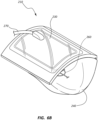
- FIGS. 6A and 6B show a second embodiment of a hemostasis device 200 that resembles the hemostasis device 100 described above in certain respects. Accordingly, like features are designated with like reference numerals, with the leading digits incremented to "2."
- the embodiment depicted in FIGS. 6A and 6B includes a compression member 210 that may, in some respects, resemble the compression member 110 of FIGS. 1 and 2A-2D .
- Relevant disclosure set forth above regarding similarly identified features thus may not be repeated hereafter.
- specific features of the hemostasis device 100 and related components shown in FIG. 1 may not be shown or identified by a reference numeral in the drawings or specifically discussed in the written description that follows FIGS. 6A and 6B .
- FIG. 6A is a top view of a second embodiment of a vascular access hemostasis device 200 configured to provide compression to the radial artery of a patient.
- the hemostasis device 200 comprises a securement system 220 and a compression member 210.
- the securement system 220 comprises two bands and may be configured to be secured to the wrist of a patient.
- the securement system 220 is coupled to the compression member 210.
- the compression member 210 as shown in FIG. 6A , is specifically configured to provide compression to the radial artery of a patient.
- the compression member 210 as described herein may be considered generic. Said another way, the compression member 210 may be configured to provide compression to other various locations on a patient, such as a wrist, hand, or foot.
- the compression member 210 may comprise a top plate 230, a bladder 240, an inflation port 250, a location indicium 260, and an inflation tube 270.
- the top plate 220 is shown partially cut out in FIG. 6A to show the location indicium 260 disposed on an inner surface of the bladder 240.
- the inflation tube 270 may be in fluid communication with the bladder 240 at one end.
- the inflation tube 270 may be coupled to and in fluid communication with the inflation port 250 at another end.
- the inflation tube 270 may also be coupled to the top plate 230 at one or more locations.
- the inflation tube 270 may in fluid communication with an orifice (not shown) extending through the top plate 230.
- FIG. 6B is a perspective view of the compression member 210.
- the top plate 230 may be rigid and may be non-flat as shown in FIG. 6B
- the top plate 230 may comprise curvature to fit partially around a patient's wrist or other portion of a patient.
- the curvature of the top plate 230 may also be configured to provide alignment of the bladder 240 with a puncture site.
- the bladder 240 is shown in an inflated state.
- the location indicium 260 as shown may be disposed on an inner surface of the bladder 240.
Landscapes
- Health & Medical Sciences (AREA)
- Life Sciences & Earth Sciences (AREA)
- Surgery (AREA)
- Heart & Thoracic Surgery (AREA)
- Molecular Biology (AREA)
- Vascular Medicine (AREA)
- Engineering & Computer Science (AREA)
- Biomedical Technology (AREA)
- Reproductive Health (AREA)
- Medical Informatics (AREA)
- Nuclear Medicine, Radiotherapy & Molecular Imaging (AREA)
- Animal Behavior & Ethology (AREA)
- General Health & Medical Sciences (AREA)
- Public Health (AREA)
- Veterinary Medicine (AREA)
- Biophysics (AREA)
- Hematology (AREA)
- Surgical Instruments (AREA)
Claims (14)
- Dispositif d'hémostase gonflable (100 ; 200), comprenant :une plaque supérieure (130 ; 230) ; etune poche (140 ; 240) couplée de manière étanche à la plaque supérieure le long d'un périmètre de la poche,dans lequel la poche (140 ; 240) comprend un sommet (170) lorsqu'elle est gonflée et un repère d'emplacement (160 ; 260) comprenant une première partie décalée linéairement du sommet et configurée pour être positionnée sur un site de ponction cutanée (PS),caractérisé en ce que le repère d'emplacement (160 ; 260) comprend en outre une deuxième partie adjacente au sommet et configurée pour être positionnée sur un site d'artériotomie (AS), et une troisième partie disposée entre la première partie et la deuxième partie et configurée pour aligner axialement la poche avec une artère (AR).
- Dispositif d'hémostase gonflable selon la revendication 1, comprenant en outre un système de fixation de dispositif d'hémostase gonflable (120 ; 220) couplé à la plaque supérieure (130 ; 230), dans lequel le système de fixation est configuré pour fixer la poche (140 ; 240) sur le site de ponction cutanée (PS).
- Dispositif d'hémostase gonflable selon l'une quelconque des revendications 1 à 2, dans lequel la poche (140 ; 240) et la plaque supérieure (130 ; 230) sont transparentes.
- Dispositif d'hémostase gonflable selon l'une quelconque des revendications 1 à 3, dans lequel un emplacement projeté (P2) de repère sur un patient vu depuis un angle de 45 degrés par rapport à un axe normal à la plaque supérieure est à moins de 3 mm d'un emplacement projeté (P1) de repère sur le patient lorsqu'il est vu selon l'axe normal.
- Dispositif d'hémostase gonflable selon l'une quelconque des revendications 1 à 4, dans lequel le repère d'emplacement (160 ; 260) est disposé sur une surface de poche.
- Dispositif d'hémostase gonflable selon l'une quelconque des revendications 1 à 5, dans lequel le repère d'emplacement (160 ; 260) est adjacent à un emplacement central de la poche (140 ; 240).
- Dispositif d'hémostase gonflable selon l'une quelconque des revendications 1 à 6, dans lequel le repère d'emplacement (160 ; 260) est situé sur une surface interne de la poche.
- Dispositif d'hémostase gonflable selon l'une quelconque des revendications 1 à 7, dans lequel le repère d'emplacement (160 ; 260) comprend une partie modifiée de manière visible d'une surface de poche.
- Dispositif d'hémostase gonflable selon l'une quelconque des revendications 1 à 8, dans lequel le repère d'emplacement (160 ; 260) comprend au moins un élément parmi un point, une extrémité de flèche, un cercle, une ellipse, un polygone, des segments de ligne entrecroisés, des segments de ligne orthogonaux et des lignes de contour et toute combinaison de ceux-ci.
- Dispositif d'hémostase gonflable selon l'une quelconque des revendications 1 à 9, dans lequel la plaque supérieure (130 ; 230) est rigide.
- Procédé d'assemblage d'un dispositif d'hémostase gonflable (100 ; 200), comprenant :l'obtention d'une plaque supérieure (130 ; 230) et d'une poche (140 ; 240), dans lequel la poche (140 ; 240) comprend un sommet (170) lorsqu'elle est gonflée ;le marquage de la poche (140 ; 240) avec un repère d'emplacement (160 ; 260), dans lequel le repère d'emplacement (160 ; 260) comprend une première partie décalée linéairement du sommet et configurée pour être positionnée sur un site de ponction cutanée (PS), une deuxième partie disposée au sommet et configurée pour être positionnée sur un site d'artériotomie (AS), et une troisième partie disposée entre la première partie et la deuxième partie et configurée pour aligner axialement la poche avec une artère (AR) ; etle couplage de manière étanche de la poche (140 ; 240) à une surface inférieure de la plaque supérieure (130 ; 230).
- Procédé selon la revendication 11, dans lequel le marquage de la poche (140 ; 240) comprend au moins un élément parmi le marquage au laser, l'apposition d'une étiquette, la gravure chimique, le piquetage à chaud, la formation de creux ou de saillies, et l'impression.
- Procédé selon la revendication 11, dans lequel le marquage de la poche (140 ; 240) comprend la disposition d'une substance visible sur une surface interne de la poche.
- Procédé selon la revendication 13, comprenant en outre la préparation de la surface interne pour le marquage comprenant au moins un élément parmi le nettoyage de la surface avec un agent de dégraissage, l'application d'un apprêt, la modification de la finition de surface et l'élimination de la charge statique.
Applications Claiming Priority (2)
| Application Number | Priority Date | Filing Date | Title |
|---|---|---|---|
| US201862656242P | 2018-04-11 | 2018-04-11 | |
| PCT/US2019/026785 WO2019199969A1 (fr) | 2018-04-11 | 2019-04-10 | Dispositif de compression gonflable |
Publications (3)
| Publication Number | Publication Date |
|---|---|
| EP3773257A1 EP3773257A1 (fr) | 2021-02-17 |
| EP3773257A4 EP3773257A4 (fr) | 2021-12-22 |
| EP3773257B1 true EP3773257B1 (fr) | 2025-02-19 |
Family
ID=68160082
Family Applications (1)
| Application Number | Title | Priority Date | Filing Date |
|---|---|---|---|
| EP19784978.9A Active EP3773257B1 (fr) | 2018-04-11 | 2019-04-10 | Dispositif de compression gonflable |
Country Status (3)
| Country | Link |
|---|---|
| US (1) | US11553925B2 (fr) |
| EP (1) | EP3773257B1 (fr) |
| WO (1) | WO2019199969A1 (fr) |
Families Citing this family (13)
| Publication number | Priority date | Publication date | Assignee | Title |
|---|---|---|---|---|
| JP7066642B2 (ja) | 2016-07-18 | 2022-05-13 | メリット・メディカル・システムズ・インコーポレイテッド | 膨張式橈骨動脈圧縮装置 |
| WO2019090104A2 (fr) | 2017-11-03 | 2019-05-09 | Merit Medical Systems, Inc. | Dispositifs d'hémostase et procédés d'utilisation |
| USD911516S1 (en) * | 2018-06-19 | 2021-02-23 | Merit Medical Systems, Inc. | Hemostasis device |
| US11627970B2 (en) * | 2019-12-20 | 2023-04-18 | Merit Medical Systems, Inc. | Inflatable surgical compression device and related systems and methods |
| CN114901159A (zh) * | 2020-03-27 | 2022-08-12 | 泰尔茂株式会社 | 压迫设备、以及压迫设备的粘贴方法 |
| EP4111987A4 (fr) * | 2020-03-27 | 2023-08-23 | TERUMO Kabushiki Kaisha | Dispositif de compression et son procédé de fixation |
| US11272941B1 (en) * | 2020-08-07 | 2022-03-15 | William P Buchanan | Secondary device holder and compression system, method of making and using the same |
| CN116113373A (zh) | 2020-08-13 | 2023-05-12 | 美国医疗设备有限公司 | 具有束紧腕带的可充气桡动脉压迫装置和使用方法 |
| USD958993S1 (en) * | 2020-12-10 | 2022-07-26 | Recovery Force, LLC | Compression device |
| JP2024047593A (ja) * | 2021-02-17 | 2024-04-08 | テルモ株式会社 | 止血器具 |
| EP4302709A4 (fr) * | 2021-03-30 | 2024-07-17 | TERUMO Kabushiki Kaisha | Instrument hémostatique |
| US12426864B2 (en) | 2021-06-18 | 2025-09-30 | Merit Medical Systems, Inc. | Hemostasis devices and methods of use |
| WO2026008854A1 (fr) * | 2024-07-05 | 2026-01-08 | Ducit Medical (Interventional Systems) Limited | Dispositif de compression d'artère radiale pour hémostase patente |
Family Cites Families (134)
| Publication number | Priority date | Publication date | Assignee | Title |
|---|---|---|---|---|
| US1281653A (en) | 1917-10-06 | 1918-10-15 | Henry W Plummer | Tourniquet. |
| US2332107A (en) | 1941-02-27 | 1943-10-19 | Nieburgs Haims Eguda | Surgical tourniquet |
| DE1006696B (de) | 1954-05-31 | 1957-04-18 | Helmut Missling Dipl Ing | Faltbare Schutzabdeckung, insbesondere fuer Fuehrungsbahnen von Werkzeugmaschinen |
| US3050064A (en) | 1959-10-22 | 1962-08-21 | Robert E Moore | Mechanical compress bandage |
| US4014011A (en) | 1975-04-25 | 1977-03-22 | Hewlett-Packard Company | Variable resolution display |
| US4390519A (en) | 1978-05-19 | 1983-06-28 | Sawyer Philip Nicholas | Bandage with hemostatic agent and methods for preparing and employing the same |
| JPS56126026A (en) | 1980-03-05 | 1981-10-02 | Hideo Inui | Bending method and its die device |
| JPS57140136A (en) | 1981-02-25 | 1982-08-30 | Sumitomo Bakelite Co Ltd | Production of reticulated thermoplastic resin article |
| GB2109239B (en) | 1981-11-13 | 1985-07-10 | Howard Charles Baron | Anatomical compression device |
| US4479495A (en) | 1982-09-27 | 1984-10-30 | Isaacson Gary S | Acupressure point stimulator device |
| US4557262A (en) | 1984-02-15 | 1985-12-10 | Snow Kenneth T | Dialysis clamp |
| US4834802A (en) | 1987-08-06 | 1989-05-30 | Prier David A | Heat generating tourniquet for venipuncture applications |
| US5139512A (en) | 1990-10-18 | 1992-08-18 | Dreiling Leo D | Semiautomatic compress |
| US5269803A (en) | 1992-04-10 | 1993-12-14 | Gtr Patent, Inc. | Hemostasis pressure pad band |
| US5304186A (en) | 1992-06-23 | 1994-04-19 | Semler Herbert J | Artery clamp |
| US5304201A (en) | 1992-09-11 | 1994-04-19 | Rice Mold Design Service, Inc. | Radial arm quick adjusting artery clamp |
| US5572997A (en) | 1994-06-14 | 1996-11-12 | Ryder International Corporation | Coagulation timer |
| US5779657A (en) | 1995-07-21 | 1998-07-14 | Daneshvar; Yousef | Nonstretchable wound cover and protector |
| AU2611797A (en) | 1995-11-17 | 1997-06-11 | I.B.S. S.R.L. | Femoral compression device for post-catheterization |
| US5695520A (en) | 1995-12-05 | 1997-12-09 | Bruckner; James V. | Pressure-applying device having plate-supported pressure-applying body secured to flexible band |
| US5728120A (en) | 1996-05-06 | 1998-03-17 | Shani; Jacob | Wrist clamp for arterial compression |
| US6231507B1 (en) | 1997-06-02 | 2001-05-15 | Vnus Medical Technologies, Inc. | Pressure tourniquet with ultrasound window and method of use |
| EP1124513A1 (fr) | 1998-09-11 | 2001-08-22 | Accumed Systems, Inc. | Attelle de poignet et dispositif d'hemostase |
| CA2254589A1 (fr) | 1998-11-27 | 2000-05-27 | Anthony Lam | Pince a artere |
| US20020188315A1 (en) | 1998-12-31 | 2002-12-12 | Guzman Jose F. | Gel tourniquet cuff |
| FR2828231B1 (fr) | 2001-08-03 | 2004-07-16 | Robert Brettes | Verin a vis telescopiques pour manipulation de vantaux |
| DE60138757D1 (de) | 2001-09-20 | 2009-07-02 | Radi Medical Systems | Einstellbare Druckvorrichtung für die Arterie radialis |
| US6746470B2 (en) | 2002-01-18 | 2004-06-08 | Mcewen James Allen | Emergency and military tourniquet for pre-hospital use |
| US6719699B2 (en) | 2002-02-07 | 2004-04-13 | Sonotech, Inc. | Adhesive hydrophilic membranes as couplants in ultrasound imaging applications |
| DE60328343D1 (de) | 2002-07-15 | 2009-08-27 | Terumo Corp | Blutstillende Vorrichtung mit aufblasbarem Ballon |
| AU2003287440A1 (en) | 2002-11-01 | 2004-06-07 | Scion Cardiovascular, Inc. | Hemostasis pad and method |
| JP4262489B2 (ja) | 2003-01-29 | 2009-05-13 | オリンパス株式会社 | 電気メス装置 |
| EP1670366B1 (fr) | 2003-10-10 | 2018-04-04 | Pyng Medical Corp. | Garrot presentant un avantage mécanique |
| US6833001B1 (en) | 2003-11-07 | 2004-12-21 | Richard C. C. Chao | Controllable tourniquet |
| US20050125025A1 (en) | 2003-12-05 | 2005-06-09 | Marcel Rioux | Styptic device |
| WO2006012745A1 (fr) | 2004-08-04 | 2006-02-09 | Bradley Allan Ross | Dispositif reglable pour comprimer des tissus |
| US20060058841A1 (en) | 2004-09-14 | 2006-03-16 | Mills Gary N | Connector for a hemostatic compression pad |
| US20060190026A1 (en) | 2005-02-24 | 2006-08-24 | Laurie Sanders | Adjustable acupressure device |
| US20070248810A1 (en) | 2006-04-25 | 2007-10-25 | Mcgee Dennis E | Coated polymeric film |
| US20070270720A1 (en) | 2006-05-04 | 2007-11-22 | Fry William R | Noninvasive physiologic pressure measurement |
| US8147417B2 (en) | 2007-01-23 | 2012-04-03 | Ohk Medical Devices Ltd. | Tourniquet timer |
| US9149280B2 (en) | 2007-05-02 | 2015-10-06 | Compression Works, Llc | Portable pneumatic abdominal aortic tourniquet with supplemental tensioning means |
| US20090209896A1 (en) | 2008-02-19 | 2009-08-20 | Selevan James R | Method and apparatus for time-dependent and temperature-dependent clinical alert |
| CN201205292Y (zh) | 2008-03-13 | 2009-03-11 | 广州市名加医疗器械制造有限公司 | 桡动脉压迫止血装置 |
| US7887497B2 (en) | 2008-03-18 | 2011-02-15 | Weber Orthopedic Inc. | Non-immobilizing thumb brace |
| US8114117B2 (en) | 2008-09-30 | 2012-02-14 | Tyco Healthcare Group Lp | Compression device with wear area |
| US8657850B2 (en) | 2008-05-06 | 2014-02-25 | Merit Medical Systems, Inc. | Radial artery compression device |
| US8353927B2 (en) | 2009-05-04 | 2013-01-15 | Merit Medical Systems, Inc. | Radial artery compression device |
| EP2430982B1 (fr) | 2008-08-26 | 2020-06-24 | St. Jude Medical, Inc. | Système d obturation de perforations percutanées |
| US20100076370A1 (en) | 2008-09-23 | 2010-03-25 | Infusion Advancements, LLC. | Apparatus and methods for purging catheter systems |
| US20100217202A1 (en) | 2009-02-21 | 2010-08-26 | Clark Timothy W I | Device for achieving hemostasis at site of puncture wound |
| WO2011044256A1 (fr) | 2009-10-06 | 2011-04-14 | Venetec International, Inc. | Dispositif médical de fixation avec minuterie |
| SE534229C2 (sv) | 2009-11-30 | 2011-06-07 | St Jude Medical Systems Ab | Kompressionssystem för kompression mot en punktionsplats på ett kärl |
| SE535548C2 (sv) | 2010-01-19 | 2012-09-18 | St Jude Medical Systems Ab | Kompressionsenhet och ett radialartärkompressionssystem |
| AU2011232934B2 (en) | 2010-03-29 | 2013-07-11 | Terumo Kabushiki Kaisha | Introducer sheath assembly |
| JP2012010823A (ja) | 2010-06-30 | 2012-01-19 | Terumo Corp | マーカ付止血器具 |
| CN201861701U (zh) | 2010-11-08 | 2011-06-15 | 中国人民解放军南京军区南京总医院 | 具有定时定压和报警功能的动脉止血压迫器 |
| SE536321C2 (sv) | 2011-02-25 | 2013-08-20 | St Jude Medical Systems Ab | Artärkompressor |
| MX355118B (es) | 2011-03-18 | 2018-04-06 | Marine Polymer Tech Inc | Métodos y aparatos para un dispositivo de compresión manual de la arteria radial. |
| US9943651B2 (en) | 2011-10-11 | 2018-04-17 | Hospitech Respiration Ltd. | Pressure regulating syringe and method therefor |
| JP2013111444A (ja) | 2011-12-01 | 2013-06-10 | Seiko Epson Corp | うっ血判定装置、脈波測定装置及びうっ血判定方法 |
| JP2013146539A (ja) | 2011-12-21 | 2013-08-01 | Nippon Koden Corp | カフ及びそれを用いた加圧下における組織観察方法 |
| US20140012120A1 (en) | 2012-03-06 | 2014-01-09 | Accumed Radial Systems, Llc | Hemostasis sensor and method of use thereof |
| US11701127B2 (en) | 2012-03-06 | 2023-07-18 | Accumed Radial Systems, Llc | Hemostasis apparatus and method |
| US10130374B2 (en) | 2012-05-11 | 2018-11-20 | Michael Zhadkevich | Anti-embolic device and method |
| EP2872079B1 (fr) | 2012-07-16 | 2021-03-24 | Valco Acquisition LLC as Designee of Wesley Holdings Ltd. | Système de surveillance d'intervention médicale |
| US9943316B2 (en) | 2012-08-13 | 2018-04-17 | Mor Research Application Ltd. | Radial artery device |
| US9463026B2 (en) | 2012-11-21 | 2016-10-11 | Medical Ingenuities, LLC | Radial compression hemostasis band with Doppler confirming vascular patency |
| JP6211285B2 (ja) | 2013-04-01 | 2017-10-11 | テルモ株式会社 | 止血器具 |
| US10390839B2 (en) | 2014-07-11 | 2019-08-27 | Semler Technologies, Inc. | Apparatus and manufacturing means for an adjustable compression wristband |
| US9308000B2 (en) | 2013-07-12 | 2016-04-12 | Vasoinnovations, Inc. | Method of transradial catheterization, device for ulnar artery compression, and method of use |
| US9332994B2 (en) | 2013-07-12 | 2016-05-10 | Vasoinnovations, Inc. | Apparatus and method to stop bleeding |
| US9427239B2 (en) | 2013-07-12 | 2016-08-30 | Semier Technologies, Inc. | Apparatus and method of use for an adjustable radial and ulnar compression wristband |
| WO2015089189A2 (fr) | 2013-12-12 | 2015-06-18 | Hollister Incorporated | Cathéters à jeter dans les toilettes |
| JP6261368B2 (ja) | 2014-02-17 | 2018-01-17 | テルモ株式会社 | 止血器具 |
| WO2015141786A1 (fr) | 2014-03-20 | 2015-09-24 | テルモ株式会社 | Instrument hémostatique |
| JP6261420B2 (ja) | 2014-03-28 | 2018-01-17 | テルモ株式会社 | 止血器具 |
| US20150327871A1 (en) * | 2014-05-15 | 2015-11-19 | Abbott Cardiovascular Systems, Inc. | Methods, systems, and devices for targeting a radial access puncture site |
| US20150327870A1 (en) * | 2014-05-15 | 2015-11-19 | Abbott Cardiovascular Systems, Inc. | Methods, systems, and devices for applying target force to a radial access puncture site |
| JP6559128B2 (ja) | 2014-06-27 | 2019-08-14 | テルモ株式会社 | 止血器具 |
| US10130799B2 (en) | 2014-08-27 | 2018-11-20 | Acclarent, Inc. | Inflator with varying mechanical advantage |
| US20160206298A1 (en) | 2015-01-21 | 2016-07-21 | Biolife, L.L.C. | Combination Hemostatic Tablet or Powder and Radial Arterial Compression Band with Syringe Assembly |
| JP6806669B2 (ja) | 2015-04-07 | 2021-01-06 | テルモ株式会社 | 止血器具 |
| JP6573309B2 (ja) | 2015-06-05 | 2019-09-11 | テルモ株式会社 | 止血器具 |
| JP6573310B2 (ja) | 2015-06-05 | 2019-09-11 | テルモ株式会社 | 止血器具 |
| JP6970402B2 (ja) | 2015-07-06 | 2021-11-24 | メリット・メディカル・システムズ・インコーポレイテッドMerit Medical Systems, Inc. | 補強シリンジ本体 |
| JP6740232B2 (ja) | 2015-09-03 | 2020-08-12 | テルモ株式会社 | 止血器具 |
| JP6667234B2 (ja) | 2015-09-03 | 2020-03-18 | テルモ株式会社 | 止血器具 |
| JP2018171081A (ja) | 2015-09-03 | 2018-11-08 | テルモ株式会社 | 止血器具 |
| CN108024818B (zh) | 2015-09-03 | 2021-07-16 | 泰尔茂株式会社 | 止血器具 |
| EP3348203B1 (fr) | 2015-09-08 | 2020-11-04 | Kurume University | Dispositif non effractif de mesure de pression artérioveineuse et méthode de mesure de pression artérioveineuse utilisant ledit dispositif de mesure |
| EP3434205A4 (fr) | 2016-03-23 | 2019-12-25 | Terumo Kabushiki Kaisha | Instrument hémostatique |
| JP6893206B2 (ja) | 2016-03-23 | 2021-06-23 | テルモ株式会社 | 止血器具 |
| CN109069163B (zh) | 2016-03-25 | 2022-10-11 | 梯日医药有限公司 | 桡侧和尺侧压迫带 |
| US10588638B2 (en) | 2016-03-25 | 2020-03-17 | Tz Medical, Inc. | Radial compression band |
| JP6725343B2 (ja) | 2016-07-06 | 2020-07-15 | テルモ株式会社 | 止血器具 |
| WO2018008604A1 (fr) | 2016-07-06 | 2018-01-11 | テルモ株式会社 | Instrument d'hémostase |
| JP6667392B2 (ja) | 2016-07-06 | 2020-03-18 | テルモ株式会社 | 止血器具 |
| CN109414271B (zh) | 2016-07-06 | 2021-08-17 | 泰尔茂株式会社 | 止血器具 |
| JP7041056B2 (ja) | 2016-07-06 | 2022-03-23 | テルモ株式会社 | 止血器具 |
| JP6783083B2 (ja) | 2016-07-06 | 2020-11-11 | テルモ株式会社 | 止血器具 |
| JP6859346B2 (ja) | 2016-07-06 | 2021-04-14 | テルモ株式会社 | 止血器具 |
| WO2018008607A1 (fr) | 2016-07-06 | 2018-01-11 | テルモ株式会社 | Instrument hémostatique |
| JP7066642B2 (ja) | 2016-07-18 | 2022-05-13 | メリット・メディカル・システムズ・インコーポレイテッド | 膨張式橈骨動脈圧縮装置 |
| JP2018011798A (ja) | 2016-07-21 | 2018-01-25 | テルモ株式会社 | 止血器具 |
| JP2018011867A (ja) | 2016-07-22 | 2018-01-25 | テルモ株式会社 | 止血器具 |
| JP2018019927A (ja) | 2016-08-03 | 2018-02-08 | テルモ株式会社 | 止血器具 |
| JP6730137B2 (ja) | 2016-08-30 | 2020-07-29 | テルモ株式会社 | 止血器具 |
| USD804663S1 (en) | 2016-09-08 | 2017-12-05 | Merit Medical Systems, Inc. | Introducer hub |
| EP3481309A4 (fr) | 2016-09-15 | 2020-04-01 | Merit Medical Systems, Inc. | Procédé de fabrication d'un dispositif gonflable de compression |
| USD821590S1 (en) | 2016-10-17 | 2018-06-26 | Children's Therapy Center | Stiffener for orthotic device |
| JP2018075257A (ja) | 2016-11-10 | 2018-05-17 | テルモ株式会社 | 止血器具 |
| WO2018181314A1 (fr) | 2017-03-29 | 2018-10-04 | テルモ株式会社 | Garrot et procédé hémostatique |
| JP6875170B2 (ja) | 2017-03-29 | 2021-05-19 | テルモ株式会社 | 止血器具 |
| JP2019047956A (ja) | 2017-09-11 | 2019-03-28 | テルモ株式会社 | 医療補助具 |
| JP7018281B2 (ja) | 2017-09-27 | 2022-02-10 | テルモ株式会社 | 止血器具 |
| US10653430B2 (en) | 2017-09-28 | 2020-05-19 | Cormed Limited | Arterial compression device and methods of using the same |
| WO2019090104A2 (fr) | 2017-11-03 | 2019-05-09 | Merit Medical Systems, Inc. | Dispositifs d'hémostase et procédés d'utilisation |
| CN208864401U (zh) | 2017-12-22 | 2019-05-17 | 孟锋 | 一种多功能桡动脉气囊压迫止血器 |
| WO2019173492A1 (fr) | 2018-03-09 | 2019-09-12 | Merit Medical Systems, Inc. | Compression vasculaire gonflable compatible avec des ultrasons et systèmes et procédés associés |
| JP2019154915A (ja) | 2018-03-15 | 2019-09-19 | テルモ株式会社 | 止血器具 |
| JP2019166265A (ja) | 2018-03-26 | 2019-10-03 | テルモ株式会社 | 止血器具 |
| JP2019208953A (ja) | 2018-06-06 | 2019-12-12 | テルモ株式会社 | 止血器具 |
| JP2019216947A (ja) | 2018-06-19 | 2019-12-26 | テルモ株式会社 | 止血器具 |
| JP2019217130A (ja) | 2018-06-22 | 2019-12-26 | テルモ株式会社 | 止血補助具及び止血方法 |
| JP2020014588A (ja) | 2018-07-24 | 2020-01-30 | テルモ株式会社 | 止血器具 |
| JP2021531152A (ja) | 2018-07-26 | 2021-11-18 | トランスルミナル テクノロジーズ エルエルシー | 吸引閉鎖装置及び方法 |
| JP2020018686A (ja) | 2018-08-02 | 2020-02-06 | テルモ株式会社 | 止血器具 |
| JP2020022679A (ja) | 2018-08-08 | 2020-02-13 | テルモ株式会社 | 止血器具 |
| USD893034S1 (en) | 2018-09-06 | 2020-08-11 | Kinesio Ip Llc | Set of adhesive tapes |
| JP7168385B2 (ja) | 2018-09-13 | 2022-11-09 | テルモ株式会社 | 止血器具 |
| JP2020039816A (ja) | 2018-09-13 | 2020-03-19 | テルモ株式会社 | 穿刺補助具及び止血器具 |
| CN209695299U (zh) | 2019-02-12 | 2019-11-29 | 吴容� | 一种心内科桡动脉介入止血压迫器 |
| CN116113373A (zh) | 2020-08-13 | 2023-05-12 | 美国医疗设备有限公司 | 具有束紧腕带的可充气桡动脉压迫装置和使用方法 |
-
2019
- 2019-04-10 US US16/380,505 patent/US11553925B2/en active Active
- 2019-04-10 EP EP19784978.9A patent/EP3773257B1/fr active Active
- 2019-04-10 WO PCT/US2019/026785 patent/WO2019199969A1/fr not_active Ceased
Also Published As
| Publication number | Publication date |
|---|---|
| US20190314035A1 (en) | 2019-10-17 |
| US11553925B2 (en) | 2023-01-17 |
| WO2019199969A1 (fr) | 2019-10-17 |
| EP3773257A4 (fr) | 2021-12-22 |
| EP3773257A1 (fr) | 2021-02-17 |
Similar Documents
| Publication | Publication Date | Title |
|---|---|---|
| EP3773257B1 (fr) | Dispositif de compression gonflable | |
| US20220370080A1 (en) | Hemostasis devices and methods of use | |
| US11229442B2 (en) | Ultrasound compatible inflatable vascular compression and related systems and methods | |
| EP3484559B1 (fr) | Dispositif gonflable de compression d'artères radiales | |
| CN109700495B (zh) | 具有多腔室囊体的组织按压装置 | |
| US4000741A (en) | Syringe assembly | |
| US20180070956A1 (en) | Method of manufacturing an inflatable compression device | |
| EP2478857A1 (fr) | Port d'accès chirurgical extensible | |
| KR20230129629A (ko) | 자궁 조작기 | |
| EP2030580A1 (fr) | Brassard d'un tensiomètre pour mesurer la pression artérielle | |
| CN116407230A (zh) | 一种便于识别感应压力的注射装置 | |
| ES2234872T3 (es) | Dispositivo de fijacion de un miembro de tubo. | |
| EP3804643A1 (fr) | Bride de contact à deux points pour joints d'instrument | |
| US20230346389A1 (en) | Inflatable surgical compression device and related systems and methods | |
| JP6726762B2 (ja) | 滲出バルーン装置 | |
| CN214388486U (zh) | 传感器组件及传感器 | |
| TWI633900B (zh) | 附有氣球的導管 | |
| AU2023219711A1 (en) | Inflatable radial artery compression device with reinforced backer plate | |
| CA1079600A (fr) | Seringue | |
| CA3027665C (fr) | Dispositif gonflable de compression d'arteres radiales | |
| CA1075117A (fr) | Seringue |
Legal Events
| Date | Code | Title | Description |
|---|---|---|---|
| STAA | Information on the status of an ep patent application or granted ep patent |
Free format text: STATUS: THE INTERNATIONAL PUBLICATION HAS BEEN MADE |
|
| PUAI | Public reference made under article 153(3) epc to a published international application that has entered the european phase |
Free format text: ORIGINAL CODE: 0009012 |
|
| STAA | Information on the status of an ep patent application or granted ep patent |
Free format text: STATUS: REQUEST FOR EXAMINATION WAS MADE |
|
| 17P | Request for examination filed |
Effective date: 20201008 |
|
| AK | Designated contracting states |
Kind code of ref document: A1 Designated state(s): AL AT BE BG CH CY CZ DE DK EE ES FI FR GB GR HR HU IE IS IT LI LT LU LV MC MK MT NL NO PL PT RO RS SE SI SK SM TR |
|
| AX | Request for extension of the european patent |
Extension state: BA ME |
|
| DAV | Request for validation of the european patent (deleted) | ||
| DAX | Request for extension of the european patent (deleted) | ||
| A4 | Supplementary search report drawn up and despatched |
Effective date: 20211123 |
|
| RIC1 | Information provided on ipc code assigned before grant |
Ipc: A61B 90/00 20160101ALN20211117BHEP Ipc: A61B 17/00 20060101ALN20211117BHEP Ipc: A61B 17/135 20060101ALI20211117BHEP Ipc: A61B 17/132 20060101AFI20211117BHEP |
|
| REG | Reference to a national code |
Ref country code: DE Ref legal event code: R079 Free format text: PREVIOUS MAIN CLASS: A61B0017135000 Ipc: A61B0017132000 Ref country code: DE Ref legal event code: R079 Ref document number: 602019066204 Country of ref document: DE Free format text: PREVIOUS MAIN CLASS: A61B0017135000 Ipc: A61B0017132000 |
|
| GRAP | Despatch of communication of intention to grant a patent |
Free format text: ORIGINAL CODE: EPIDOSNIGR1 |
|
| STAA | Information on the status of an ep patent application or granted ep patent |
Free format text: STATUS: GRANT OF PATENT IS INTENDED |
|
| RIC1 | Information provided on ipc code assigned before grant |
Ipc: A61B 90/00 20160101ALN20240807BHEP Ipc: A61B 17/00 20060101ALN20240807BHEP Ipc: A61B 17/135 20060101ALI20240807BHEP Ipc: A61B 17/132 20060101AFI20240807BHEP |
|
| RIC1 | Information provided on ipc code assigned before grant |
Ipc: A61B 90/00 20160101ALN20240816BHEP Ipc: A61B 17/00 20060101ALN20240816BHEP Ipc: A61B 17/135 20060101ALI20240816BHEP Ipc: A61B 17/132 20060101AFI20240816BHEP |
|
| INTG | Intention to grant announced |
Effective date: 20240910 |
|
| GRAS | Grant fee paid |
Free format text: ORIGINAL CODE: EPIDOSNIGR3 |
|
| GRAA | (expected) grant |
Free format text: ORIGINAL CODE: 0009210 |
|
| STAA | Information on the status of an ep patent application or granted ep patent |
Free format text: STATUS: THE PATENT HAS BEEN GRANTED |
|
| AK | Designated contracting states |
Kind code of ref document: B1 Designated state(s): AL AT BE BG CH CY CZ DE DK EE ES FI FR GB GR HR HU IE IS IT LI LT LU LV MC MK MT NL NO PL PT RO RS SE SI SK SM TR |
|
| P01 | Opt-out of the competence of the unified patent court (upc) registered |
Free format text: CASE NUMBER: APP_1680/2025 Effective date: 20250110 |
|
| REG | Reference to a national code |
Ref country code: GB Ref legal event code: FG4D |
|
| REG | Reference to a national code |
Ref country code: CH Ref legal event code: EP |
|
| REG | Reference to a national code |
Ref country code: IE Ref legal event code: FG4D |
|
| REG | Reference to a national code |
Ref country code: DE Ref legal event code: R096 Ref document number: 602019066204 Country of ref document: DE |
|
| REG | Reference to a national code |
Ref country code: NL Ref legal event code: FP |
|
| PG25 | Lapsed in a contracting state [announced via postgrant information from national office to epo] |
Ref country code: RS Free format text: LAPSE BECAUSE OF FAILURE TO SUBMIT A TRANSLATION OF THE DESCRIPTION OR TO PAY THE FEE WITHIN THE PRESCRIBED TIME-LIMIT Effective date: 20250519 |
|
| PG25 | Lapsed in a contracting state [announced via postgrant information from national office to epo] |
Ref country code: FI Free format text: LAPSE BECAUSE OF FAILURE TO SUBMIT A TRANSLATION OF THE DESCRIPTION OR TO PAY THE FEE WITHIN THE PRESCRIBED TIME-LIMIT Effective date: 20250219 |
|
| PG25 | Lapsed in a contracting state [announced via postgrant information from national office to epo] |
Ref country code: PL Free format text: LAPSE BECAUSE OF FAILURE TO SUBMIT A TRANSLATION OF THE DESCRIPTION OR TO PAY THE FEE WITHIN THE PRESCRIBED TIME-LIMIT Effective date: 20250219 |
|
| PGFP | Annual fee paid to national office [announced via postgrant information from national office to epo] |
Ref country code: DE Payment date: 20250325 Year of fee payment: 7 |
|
| PG25 | Lapsed in a contracting state [announced via postgrant information from national office to epo] |
Ref country code: ES Free format text: LAPSE BECAUSE OF FAILURE TO SUBMIT A TRANSLATION OF THE DESCRIPTION OR TO PAY THE FEE WITHIN THE PRESCRIBED TIME-LIMIT Effective date: 20250219 |
|
| REG | Reference to a national code |
Ref country code: LT Ref legal event code: MG9D |
|
| PG25 | Lapsed in a contracting state [announced via postgrant information from national office to epo] |
Ref country code: NO Free format text: LAPSE BECAUSE OF FAILURE TO SUBMIT A TRANSLATION OF THE DESCRIPTION OR TO PAY THE FEE WITHIN THE PRESCRIBED TIME-LIMIT Effective date: 20250519 Ref country code: IS Free format text: LAPSE BECAUSE OF FAILURE TO SUBMIT A TRANSLATION OF THE DESCRIPTION OR TO PAY THE FEE WITHIN THE PRESCRIBED TIME-LIMIT Effective date: 20250619 |
|
| PG25 | Lapsed in a contracting state [announced via postgrant information from national office to epo] |
Ref country code: HR Free format text: LAPSE BECAUSE OF FAILURE TO SUBMIT A TRANSLATION OF THE DESCRIPTION OR TO PAY THE FEE WITHIN THE PRESCRIBED TIME-LIMIT Effective date: 20250219 |
|
| PG25 | Lapsed in a contracting state [announced via postgrant information from national office to epo] |
Ref country code: PT Free format text: LAPSE BECAUSE OF FAILURE TO SUBMIT A TRANSLATION OF THE DESCRIPTION OR TO PAY THE FEE WITHIN THE PRESCRIBED TIME-LIMIT Effective date: 20250620 Ref country code: LV Free format text: LAPSE BECAUSE OF FAILURE TO SUBMIT A TRANSLATION OF THE DESCRIPTION OR TO PAY THE FEE WITHIN THE PRESCRIBED TIME-LIMIT Effective date: 20250219 |
|
| PG25 | Lapsed in a contracting state [announced via postgrant information from national office to epo] |
Ref country code: GR Free format text: LAPSE BECAUSE OF FAILURE TO SUBMIT A TRANSLATION OF THE DESCRIPTION OR TO PAY THE FEE WITHIN THE PRESCRIBED TIME-LIMIT Effective date: 20250520 Ref country code: BG Free format text: LAPSE BECAUSE OF FAILURE TO SUBMIT A TRANSLATION OF THE DESCRIPTION OR TO PAY THE FEE WITHIN THE PRESCRIBED TIME-LIMIT Effective date: 20250219 |
|
| REG | Reference to a national code |
Ref country code: AT Ref legal event code: MK05 Ref document number: 1767551 Country of ref document: AT Kind code of ref document: T Effective date: 20250219 |
|
| PG25 | Lapsed in a contracting state [announced via postgrant information from national office to epo] |
Ref country code: SE Free format text: LAPSE BECAUSE OF FAILURE TO SUBMIT A TRANSLATION OF THE DESCRIPTION OR TO PAY THE FEE WITHIN THE PRESCRIBED TIME-LIMIT Effective date: 20250219 |
|
| PG25 | Lapsed in a contracting state [announced via postgrant information from national office to epo] |
Ref country code: SM Free format text: LAPSE BECAUSE OF FAILURE TO SUBMIT A TRANSLATION OF THE DESCRIPTION OR TO PAY THE FEE WITHIN THE PRESCRIBED TIME-LIMIT Effective date: 20250219 |
|
| PG25 | Lapsed in a contracting state [announced via postgrant information from national office to epo] |
Ref country code: DK Free format text: LAPSE BECAUSE OF FAILURE TO SUBMIT A TRANSLATION OF THE DESCRIPTION OR TO PAY THE FEE WITHIN THE PRESCRIBED TIME-LIMIT Effective date: 20250219 |
|
| PG25 | Lapsed in a contracting state [announced via postgrant information from national office to epo] |
Ref country code: AT Free format text: LAPSE BECAUSE OF FAILURE TO SUBMIT A TRANSLATION OF THE DESCRIPTION OR TO PAY THE FEE WITHIN THE PRESCRIBED TIME-LIMIT Effective date: 20250219 |
|
| PG25 | Lapsed in a contracting state [announced via postgrant information from national office to epo] |
Ref country code: EE Free format text: LAPSE BECAUSE OF FAILURE TO SUBMIT A TRANSLATION OF THE DESCRIPTION OR TO PAY THE FEE WITHIN THE PRESCRIBED TIME-LIMIT Effective date: 20250219 Ref country code: CZ Free format text: LAPSE BECAUSE OF FAILURE TO SUBMIT A TRANSLATION OF THE DESCRIPTION OR TO PAY THE FEE WITHIN THE PRESCRIBED TIME-LIMIT Effective date: 20250219 |
|
| PG25 | Lapsed in a contracting state [announced via postgrant information from national office to epo] |
Ref country code: RO Free format text: LAPSE BECAUSE OF FAILURE TO SUBMIT A TRANSLATION OF THE DESCRIPTION OR TO PAY THE FEE WITHIN THE PRESCRIBED TIME-LIMIT Effective date: 20250219 |
|
| PG25 | Lapsed in a contracting state [announced via postgrant information from national office to epo] |
Ref country code: SK Free format text: LAPSE BECAUSE OF FAILURE TO SUBMIT A TRANSLATION OF THE DESCRIPTION OR TO PAY THE FEE WITHIN THE PRESCRIBED TIME-LIMIT Effective date: 20250219 |
|
| REG | Reference to a national code |
Ref country code: DE Ref legal event code: R097 Ref document number: 602019066204 Country of ref document: DE |
|
| REG | Reference to a national code |
Ref country code: CH Ref legal event code: H13 Free format text: ST27 STATUS EVENT CODE: U-0-0-H10-H13 (AS PROVIDED BY THE NATIONAL OFFICE) Effective date: 20251125 |
|
| PG25 | Lapsed in a contracting state [announced via postgrant information from national office to epo] |
Ref country code: LU Free format text: LAPSE BECAUSE OF NON-PAYMENT OF DUE FEES Effective date: 20250410 |
|
| PG25 | Lapsed in a contracting state [announced via postgrant information from national office to epo] |
Ref country code: MC Free format text: LAPSE BECAUSE OF FAILURE TO SUBMIT A TRANSLATION OF THE DESCRIPTION OR TO PAY THE FEE WITHIN THE PRESCRIBED TIME-LIMIT Effective date: 20250219 |
|
| PLBE | No opposition filed within time limit |
Free format text: ORIGINAL CODE: 0009261 |
|
| STAA | Information on the status of an ep patent application or granted ep patent |
Free format text: STATUS: NO OPPOSITION FILED WITHIN TIME LIMIT |
|
| REG | Reference to a national code |
Ref country code: BE Ref legal event code: MM Effective date: 20250430 |
|
| PG25 | Lapsed in a contracting state [announced via postgrant information from national office to epo] |
Ref country code: FR Free format text: LAPSE BECAUSE OF NON-PAYMENT OF DUE FEES Effective date: 20250419 |
|
| PG25 | Lapsed in a contracting state [announced via postgrant information from national office to epo] |
Ref country code: BE Free format text: LAPSE BECAUSE OF NON-PAYMENT OF DUE FEES Effective date: 20250430 |
|
| PG25 | Lapsed in a contracting state [announced via postgrant information from national office to epo] |
Ref country code: CH Free format text: LAPSE BECAUSE OF NON-PAYMENT OF DUE FEES Effective date: 20250430 |
|
| 26N | No opposition filed |
Effective date: 20251120 |
|
| PGFP | Annual fee paid to national office [announced via postgrant information from national office to epo] |
Ref country code: NL Payment date: 20260227 Year of fee payment: 8 |
|
| PGFP | Annual fee paid to national office [announced via postgrant information from national office to epo] |
Ref country code: GB Payment date: 20260223 Year of fee payment: 8 |
|
| PG25 | Lapsed in a contracting state [announced via postgrant information from national office to epo] |
Ref country code: IE Free format text: LAPSE BECAUSE OF NON-PAYMENT OF DUE FEES Effective date: 20250410 |
|
| PGFP | Annual fee paid to national office [announced via postgrant information from national office to epo] |
Ref country code: IT Payment date: 20260320 Year of fee payment: 8 |