EP3773264B1 - Elektroden-applikationsinstrument - Google Patents
Elektroden-applikationsinstrument Download PDFInfo
- Publication number
- EP3773264B1 EP3773264B1 EP19714427.2A EP19714427A EP3773264B1 EP 3773264 B1 EP3773264 B1 EP 3773264B1 EP 19714427 A EP19714427 A EP 19714427A EP 3773264 B1 EP3773264 B1 EP 3773264B1
- Authority
- EP
- European Patent Office
- Prior art keywords
- branch
- instrument
- branches
- electrode application
- shaped
- Prior art date
- Legal status (The legal status is an assumption and is not a legal conclusion. Google has not performed a legal analysis and makes no representation as to the accuracy of the status listed.)
- Active
Links
Images

Classifications
-
- A—HUMAN NECESSITIES
- A61—MEDICAL OR VETERINARY SCIENCE; HYGIENE
- A61B—DIAGNOSIS; SURGERY; IDENTIFICATION
- A61B17/00—Surgical instruments, devices or methods
- A61B17/28—Surgical forceps
- A61B17/29—Forceps for use in minimally invasive surgery
- A61B17/2909—Handles
-
- A—HUMAN NECESSITIES
- A61—MEDICAL OR VETERINARY SCIENCE; HYGIENE
- A61B—DIAGNOSIS; SURGERY; IDENTIFICATION
- A61B17/00—Surgical instruments, devices or methods
- A61B17/28—Surgical forceps
- A61B17/29—Forceps for use in minimally invasive surgery
-
- A—HUMAN NECESSITIES
- A61—MEDICAL OR VETERINARY SCIENCE; HYGIENE
- A61N—ELECTROTHERAPY; MAGNETOTHERAPY; RADIATION THERAPY; ULTRASOUND THERAPY
- A61N1/00—Electrotherapy; Circuits therefor
- A61N1/02—Details
- A61N1/04—Electrodes
- A61N1/05—Electrodes for implantation or insertion into the body, e.g. heart electrode
- A61N1/056—Transvascular endocardial electrode systems
- A61N1/057—Anchoring means; Means for fixing the head inside the heart
-
- A—HUMAN NECESSITIES
- A61—MEDICAL OR VETERINARY SCIENCE; HYGIENE
- A61N—ELECTROTHERAPY; MAGNETOTHERAPY; RADIATION THERAPY; ULTRASOUND THERAPY
- A61N1/00—Electrotherapy; Circuits therefor
- A61N1/02—Details
- A61N1/04—Electrodes
- A61N1/05—Electrodes for implantation or insertion into the body, e.g. heart electrode
- A61N1/0587—Epicardial electrode systems; Endocardial electrodes piercing the pericardium
-
- A—HUMAN NECESSITIES
- A61—MEDICAL OR VETERINARY SCIENCE; HYGIENE
- A61N—ELECTROTHERAPY; MAGNETOTHERAPY; RADIATION THERAPY; ULTRASOUND THERAPY
- A61N1/00—Electrotherapy; Circuits therefor
- A61N1/02—Details
- A61N1/04—Electrodes
- A61N1/05—Electrodes for implantation or insertion into the body, e.g. heart electrode
- A61N1/0587—Epicardial electrode systems; Endocardial electrodes piercing the pericardium
- A61N1/059—Anchoring means
-
- A—HUMAN NECESSITIES
- A61—MEDICAL OR VETERINARY SCIENCE; HYGIENE
- A61B—DIAGNOSIS; SURGERY; IDENTIFICATION
- A61B17/00—Surgical instruments, devices or methods
- A61B17/00234—Surgical instruments, devices or methods for minimally invasive surgery
- A61B2017/00238—Type of minimally invasive operation
- A61B2017/00243—Type of minimally invasive operation cardiac
-
- A—HUMAN NECESSITIES
- A61—MEDICAL OR VETERINARY SCIENCE; HYGIENE
- A61B—DIAGNOSIS; SURGERY; IDENTIFICATION
- A61B17/00—Surgical instruments, devices or methods
- A61B17/00234—Surgical instruments, devices or methods for minimally invasive surgery
- A61B2017/00292—Surgical instruments, devices or methods for minimally invasive surgery mounted on or guided by flexible, e.g. catheter-like, means
- A61B2017/003—Steerable
-
- A—HUMAN NECESSITIES
- A61—MEDICAL OR VETERINARY SCIENCE; HYGIENE
- A61B—DIAGNOSIS; SURGERY; IDENTIFICATION
- A61B17/00—Surgical instruments, devices or methods
- A61B17/28—Surgical forceps
- A61B17/29—Forceps for use in minimally invasive surgery
- A61B17/2909—Handles
- A61B2017/2912—Handles transmission of forces to actuating rod or piston
- A61B2017/2913—Handles transmission of forces to actuating rod or piston cams or guiding means
- A61B2017/2916—Handles transmission of forces to actuating rod or piston cams or guiding means pins in guiding slots
-
- A—HUMAN NECESSITIES
- A61—MEDICAL OR VETERINARY SCIENCE; HYGIENE
- A61B—DIAGNOSIS; SURGERY; IDENTIFICATION
- A61B17/00—Surgical instruments, devices or methods
- A61B17/28—Surgical forceps
- A61B17/29—Forceps for use in minimally invasive surgery
- A61B2017/2926—Details of heads or jaws
-
- A—HUMAN NECESSITIES
- A61—MEDICAL OR VETERINARY SCIENCE; HYGIENE
- A61B—DIAGNOSIS; SURGERY; IDENTIFICATION
- A61B17/00—Surgical instruments, devices or methods
- A61B17/28—Surgical forceps
- A61B17/29—Forceps for use in minimally invasive surgery
- A61B2017/2926—Details of heads or jaws
- A61B2017/2927—Details of heads or jaws the angular position of the head being adjustable with respect to the shaft
-
- A—HUMAN NECESSITIES
- A61—MEDICAL OR VETERINARY SCIENCE; HYGIENE
- A61B—DIAGNOSIS; SURGERY; IDENTIFICATION
- A61B17/00—Surgical instruments, devices or methods
- A61B17/28—Surgical forceps
- A61B17/29—Forceps for use in minimally invasive surgery
- A61B2017/2926—Details of heads or jaws
- A61B2017/2927—Details of heads or jaws the angular position of the head being adjustable with respect to the shaft
- A61B2017/2929—Details of heads or jaws the angular position of the head being adjustable with respect to the shaft with a head rotatable about the longitudinal axis of the shaft
-
- A—HUMAN NECESSITIES
- A61—MEDICAL OR VETERINARY SCIENCE; HYGIENE
- A61B—DIAGNOSIS; SURGERY; IDENTIFICATION
- A61B17/00—Surgical instruments, devices or methods
- A61B17/28—Surgical forceps
- A61B17/29—Forceps for use in minimally invasive surgery
- A61B2017/2926—Details of heads or jaws
- A61B2017/2932—Transmission of forces to jaw members
- A61B2017/2933—Transmission of forces to jaw members camming or guiding means
- A61B2017/2936—Pins in guiding slots
-
- A—HUMAN NECESSITIES
- A61—MEDICAL OR VETERINARY SCIENCE; HYGIENE
- A61N—ELECTROTHERAPY; MAGNETOTHERAPY; RADIATION THERAPY; ULTRASOUND THERAPY
- A61N1/00—Electrotherapy; Circuits therefor
- A61N1/02—Details
- A61N1/04—Electrodes
- A61N1/05—Electrodes for implantation or insertion into the body, e.g. heart electrode
- A61N1/056—Transvascular endocardial electrode systems
- A61N1/057—Anchoring means; Means for fixing the head inside the heart
- A61N2001/058—Fixing tools
Definitions
- the present invention relates to an electrode application instrument of minimally invasive design according to the preamble of claim 1.
- pacemakers are often implanted in the patient. These are electrically connected to certain areas of the heart via electrical leads and electrodes mounted on the ends. It is crucial that the electrodes are correctly and safely installed/placed/anchored to the heart.
- the electrodes have screw- or corkscrew-like extensions/anchors that are screwed into the muscle tissue of the heart.
- electrodes of this type can be inserted into the interior of the heart via the carotid artery using a catheter and fixed there. This has the advantage that the patient is only slightly injured during the operation (minimal surgical trauma) and the risk of infection can therefore be minimized as much as possible. However, this procedure has the disadvantage that positioning the electrodes is difficult and sometimes inaccurate.
- electrodes of this type can be placed on the outside of the heart in a minimally invasive manner using a shaft-type surgical instrument. For this purpose, for example, a minimally invasive patient access is created through which the shaft of the surgical instrument can be inserted.
- a shaft-type electrode application instrument is known.
- This instrument has a handle that is connected to a proximal end of an instrument shaft, at the distal end of which an effector is pivotably and rotatably mounted.
- the effector forms a jaw part/instrument head for receiving an electrode for its application to the outer wall of a heart.
- the jaw part is designed in the shape of a tulip with three or four spring-elastic tabs spaced apart in the circumferential direction, which form a type of receiving ring into which an electrode can be clamped.
- semicircular recesses or notches are formed between the tabs on the front side, through which the electrode strands can be guided when the electrode is clamped in the receiving ring.
- an object of the present invention to provide an electrode application instrument with which the application of electrodes, in particular to the heart muscle, can be carried out in a simple and safe manner.
- the present disclosure relates to a surgical electrode application instrument of minimally invasive design with an effector which forms an instrument head which is mounted at the distal end of an instrument shaft so as to be rotatable and pivotable about its longitudinal axis, on which two opposing branches are mounted which can be moved towards one another like scissors or pliers, of which at least one branch is designed with a partially circular notch on the front side for receiving an electrode wire and which are each shaped in a sickle-shaped cross-section at least in sections, wherein the clamping sides facing one another in the sickle-shaped section of each branch each have a number, preferably a plurality, of grooves or undercuts which are spaced apart in the longitudinal direction of the branch and preferably run parallel in the transverse direction of the branch, wherein at least one or both branches are designed for their active actuation with articulation points for an actuating mechanism which has a number of actuating elements, one of which is coupled to the branches at the corresponding articulation point via a gear train, such that an
- the core of the present invention therefore consists in the special design of the effector or jaw part with two opposing branches that can be moved towards each other like a pair of pliers, of which at least one branch (preferably both) is designed with a partially circular notch on the front side (for receiving an electrode wire) and which are each bent or shaped in a sickle shape in cross-section (when viewed in the proximal direction), whereby a groove shape extending in the longitudinal direction (proximal direction) is produced on the inner sides of the branches facing each other (at least in the area of an engagement section of the branch).
- each branch facing each other also each have a number of (inner circumferential) grooves or undercuts spaced apart in the axial direction, which preferably have the same radii or groove depths and are used to (axially) receive an electrode (i.e. to receive the generally button- or plate-shaped electrode not from the side but from above).
- the branches of the jaw part are mounted on an instrument head in an articulated/pivotable manner and are coupled to a handle via an actuating device/gear train.
- the instrument head is pivotable and rotatable (around its longitudinal axis) at a distal end of an instrument shaft.
- the handle is arranged at a proximal end of the instrument shaft, with the actuating device/gear train being provided (at least partially) within the instrument shaft.
- the handle has a number of actuating elements that are integrated in a handle in order to rotate the instrument head around its longitudinal axis in a separate manner, to angle/pivot it with respect to the instrument shaft and to open/close the branches.
- the two branches of the jaw part are preferably designed to be identical to one another and more preferably have a branch neck that is offset from the axis in a top view or bottom view (looking towards the clamping side of the engagement section), which distally merges into an axially centrally arranged engagement section/gripping section in one piece.
- the engagement section has the contour curved in a sickle shape in cross section as described above, is preferably designed to be smooth on its radial outer side and is provided on its radial inner side with the above-described axially spaced and circumferentially extending grooves.
- the branch neck is preferably shaped like a plate with a through hole at the distal transition area between the branch neck and a gripping section and more preferably an axially extending, but obliquely positioned elongated hole in the proximal end section of the branch neck.
- the plate-like branch neck is preferably rotated by approx. 90° to the gripping section, such that the through hole and the elongated hole are aligned in the transverse direction of the branch (along the inner circumferential grooves).
- the branches can be mounted in an instrument head in a scissor-like manner at the respective through hole, with the respective elongated hole forming a type of sliding gate, such that, for example, a cross pin guided longitudinally in the instrument head passes through the elongated hole and, during its longitudinal movement, the branch rotates around the hinge as a result of the oblique position of the elongated hole.
- the translation of the sliding movement of the branch gear train can also be transformed into a pivoting movement of the branches by another mechanism (e.g. via connecting rods).
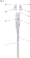
- the surgical instrument 1 shown for applying electrodes (not shown further), for example, to a patient's heart has a handle 2 in the form of a grip piece that is mounted on the proximal end of an instrument shaft 4.
- An effector in the form of an instrument head 6 is mounted on the distal end of the instrument shaft 4, which is mounted on the instrument shaft so as to be rotatable about its longitudinal axis S and pivotable with respect to the longitudinal axis of the instrument shaft.
- two branches 8a, 8b are mounted like scissors or forceps (see in particular Fig. 2 ) such that they can be rotated and pivoted together with the instrument head 6 and can be opened and closed independently thereof.
- the instrument handle 2 has a type of joystick 10 which is mounted on a handle base 16 in a pivotable or foldable manner and is coupled to the instrument head 6 via a gear system guided in the instrument shaft 4 in such a way that a pivoting movement of the joystick 10 with respect to the handle base 16 is transformed into a pivoting movement of the instrument head 6 with respect to the instrument shaft 4.
- a pivoting lever 12 is articulated on the joystick 10, the pivoting movement of which with respect to the joystick 10 is transmitted to the branches 8a, 8b via a separate gear train also guided in the instrument shaft 4 in order to open and close them like scissors or pincers.
- a rotary knob 14 is mounted on the free end of the control stick 10, the rotation of which acts on the instrument head 6 via a gear train also arranged separately in the instrument shaft 4 in order to rotate the latter about its longitudinal axis.
- the surgical instrument for applying electrodes differs from the previously known surgical instruments of the minimally invasive design essentially in the construction of the branches 8a, 8b used according to the invention.
- Electrodes of known design for mounting on a patient's heart generally have a coin- or button-shaped (flat and round) electrode head, on the flat underside of which a corkscrew-like screw spiral/anchor is arranged, which can be connected to a pacemaker, for example, via an electrical wire (cable).
- a pacemaker for example, via an electrical wire (cable).
- Such an electrode must be screwed into the heart muscle in order to be attached, and it is crucial for its secure hold in the comparatively spongy heart muscle tissue that the screwing in process takes place as axially as possible along the screw spiral, without performing a rocking or wobbling movement. This means that the electrode must be grasped and held in such a way that the screw spiral extends essentially axially to the longitudinal axis of the instrument head 6.
- branches 8a, 8b provided in the instrument 1 according to the invention have a construction as is particularly known in the Figures 2 to 5 is shown.
- branches 8a, 8b mounted on the instrument head 6 in the manner of scissors or forceps are preferably of identical construction, so that only one of the two branches needs to be described below.
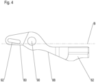
- Each branch 8a, 8b therefore has a proximal branch neck 80 and a distal gripping section 82 which is integrally connected to it (via an intermediate transition area).
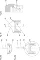
- the gripping section 82 is formed by a plate which is sickle-shaped or groove-shaped in cross-section (seen in the longitudinal direction of the branch) (see Fig:5a ), which has a semi-circular notch 84 on its distal end face (see Fig. 5b ) which is arranged substantially centrally with respect to the branch longitudinal axis B.
- a (radial) outer side of the gripping section 82 is preferably designed to be smooth, whereas a (radial) inner side of the gripping section (hereinafter referred to as the clamping side) has a grooved profile.
- the groove profile consists of a number of grooves 86 spaced apart in the direction of the branch axis, which extend in the transverse direction or in the circumferential direction of the gripping section 82 and thus essentially perpendicular to the branch longitudinal axis B over the entire gripping section 82. Furthermore, all grooves 86 preferably have the same radius or the same groove depth. The groove width also preferably remains the same, but can change starting from distal in the proximal direction.
- the branch neck 80 has a plate-like or plate-like shape and is rotated by essentially 90° around the longitudinal axis of the branch relative to the gripping section 82. This means that while the gripping section 82 is aligned quasi horizontally, for example, the plate-shaped branch neck 80 extends essentially vertically.
- a through-hole 90 is formed in a distal transition region 88 between the branch neck 80 and the gripping section 82, which extends essentially along (tangentially) the grooves 86 as a result of the 90° rotation.
- a slot 92 is also formed in a proximal end section of the branch neck 82, which extends along the longitudinal axis of the branch, but is also set at an (acute) angle (for example 15°-20°) to the longitudinal axis of the branch.
- the longitudinal axis of the branches in the area of the branch neck 80 and the longitudinal axis of the branch in the area of the gripping section 82 run essentially parallel to each other, whereas the longitudinal axis of the branch B in the transition area 88 between the branch neck 80 and the gripping section 82 is inclined to this in the side view, which results in an S-shaped branch course in the side view. Consequently, the two branches 8a, 8b mounted on the instrument head 6 like scissors or pliers form a clamping gap between the opposite clamping sides when the two branches 8a, 8b are in a position in which the clamping sides are aligned parallel to each other. This position is, for example, in the Fig. 2 shown.
- the branch neck 80 and the gripping section 82 are arranged asymmetrically when viewed from below (ie looking at the clamping side of the gripping section 82).
- the branch neck 80 is arranged with respect to the central or longitudinal axis (Branch longitudinal axis B) of the gripping section 82, such that when two branches 8a, 8b lie against each other in the region of the branch necks 82, the two opposite clamping sides are essentially aligned or overlap.
- the electrode is gripped at the edge with the scissor-like branches 8a, 8b mounted on the instrument head, such that the electrode edge engages in the same grooves on the opposing branches. This ensures that the electrode is aligned essentially perpendicular to the instrument head axis. Care must be taken to ensure that the electrode edge is received in the groove with a certain radius so that the two branches are aligned essentially parallel to each other when the electrode is held.
- the gripping process is essentially carried out by actuating the lever 12, whereby a pin or pin 91 mounted in the instrument head 6 in an axially displaceable manner is displaced longitudinally via the associated gear train in the instrument shaft 4, which in turn engages in the elongated holes 92. Due to the inclination of the elongated holes 92 with respect to the branch longitudinal axis B or the instrument head longitudinal axis S, the elongated holes 92 act as guide slots, such that when the pin/pin 91 is axially displaced along the elongated holes 92, the branches 8a, 8b are simultaneously rotated about a pivot pin 93 inserted into the through holes 90.
- the electrode can now be screwed into the heart muscle by pivoting the instrument head 6 so that it is aligned essentially perpendicular to the outside of the heart and then rotating the instrument head and the branches 8a, 8b forming the jaw part. As soon as the electrode is firmly screwed into the heart muscle, the branches 8a, 8b can be opened and the electrode can be released.
Landscapes
- Health & Medical Sciences (AREA)
- Heart & Thoracic Surgery (AREA)
- Life Sciences & Earth Sciences (AREA)
- Engineering & Computer Science (AREA)
- Veterinary Medicine (AREA)
- Biomedical Technology (AREA)
- Nuclear Medicine, Radiotherapy & Molecular Imaging (AREA)
- Animal Behavior & Ethology (AREA)
- General Health & Medical Sciences (AREA)
- Public Health (AREA)
- Surgery (AREA)
- Cardiology (AREA)
- Radiology & Medical Imaging (AREA)
- Ophthalmology & Optometry (AREA)
- Medical Informatics (AREA)
- Molecular Biology (AREA)
- Vascular Medicine (AREA)
- Surgical Instruments (AREA)
- Electrotherapy Devices (AREA)
Description
- Die vorliegende Erfindung betrifft ein Elektroden-Applikationsinstrument der minimalinvasiven Bauart gemäß dem Oberbegriff des Schutzanspruchs 1.
- Beispielsweise im Falle von Herzrhythmusstörungen werden häufig dem Patienten Herzschrittmacher implantiert, welche über elektrische Leitungen sowie daran endseitig montierte Elektroden mit bestimmten Bereichen des Herzens elektrisch verbunden sind. Entscheidend ist es hierbei, dass die Elektroden korrekt und sicher am Herzen installiert/gesetzt/verankert werden. Zu diesem Zweck weisen die Elektroden schrauben- oder korkenzieherartige Fortsätze/Anker auf, die in das Muskelgewebe des Herzens eingedreht werden.
- Für die Implantation derartiger Elektroden haben sich in der Vergangenheit zwei Vorgehensweisen etabliert. Zum einen können Elektroden dieser Gattung per Katheter über die Halsschlagader in das Innere des Herzens eingeführt und dort fixiert werden. Dies hat den Vorteil, dass der Patient nur geringfügig operativ verletzt wird (geringes Operationstrauma) und daher das Infektionsrisiko weitestgehend minimiert werden kann. Jedoch hat diese Vorgehensweise den Nachteil, dass die Positionierung der Elektroden schwierig und teilweise auch ungenau ist. Zum anderen können Elektroden dieser Gattung minimalinvasiv mittels eines chirurgischen Instruments der Schaftbauart an die Außenseite des Herzens gesetzt werden. Zu diesem Zweck wird beispielsweise ein minimalinvasiver Patientenzugang geschaffen, durch welchen der Instrumentenschaft des chirurgischen Instruments eingeführt werden kann.
- Aus dem Stand der Technik beispielsweise gemäß der
US 7,544, 197B2 ist ein Elektroden-Applikationsinstrument der Schaftbauart bekannt. Dieses Instrument hat einen Handgriff, der an einem proximalen Ende eines Instrumentenschafts angeschlossen ist, an dessen distalem Ende ein Effektor schwenkbar sowie drehbar gelagert ist. Der Effektor bildet ein Maulteil/Instrumentenkopf zur Aufnahme einer Elektrode für deren Applikation an der Außenwand eines Herzens. Das Maulteil ist in Form einer Tulpe aufgebaut mit drei oder vier in Umfangsrichtung beabstandeten federelastischen Laschen, die eine Art Aufnahmering bilden, in welchen eine Elektrode eingeklemmt werden kann. Darüber hinaus bilden sich zwischen den Laschen stirnseitige halbrunde Ausnehmungen oder Einkerbungen, durch welche die Elektrodenlitzen geführt werden können, wenn die Elektrode in dem Aufnahmering eingeklemmt ist. - Es hat sich gezeigt, dass ein derart gestaltetes Maulteil zwar die Elektrode sicher halten und Einschrauben kann, jedoch die Elektrode nach deren Befestigung am Herzmuskel nicht einfach freigeben kann.
- Angesichts dieser Problematik ist es eine Aufgabe der vorliegenden Erfindung, ein Elektroden-Applikationsinstrument bereitzustellen, mit welchem das Applizieren von Elektroden insbesondere am Herzmuskel in einfacher und sicherer Weise durchgeführt werden kann.
- Diese Aufgabe wird durch ein chirurgisches Instrument, insbesondere Elektroden-Applikationsinstrument der minimalinvasiven Bauart mit den Merkmalen des Schutzanspruchs 1 gelöst. Vorteilhafte Weiterbildungen der Erfindung sind Gegenstand der abhängigen Ansprüche.
- Genauer betrifft die vorliegende Offenbarung ein chirurgisches Elektroden-Applikationsinstrument der minimalinvasiven Bauart mit einem Effektor, der einen am distalen Ende eines Instrumentenschafts um dessen Längsachse drehbar sowie schwenkbar gelagerten Instrumentenkopf bildet, an welchem zwei sich gegenüberliegende sowie scheren- oder zangenartig aufeinander zu bewegbare Branchen gelagert sind, von denen zumindest eine Branche mit einer stirnseitigen teilkreisförmigen Einkerbung für die Aufnahme einer Elektrodenlitze ausgebildet ist und die zumindest abschnittsweise jeweils im Querschnitt sichelförmig geformt sind, wobei die einander zugewandten Klemmseiten im sichelförmig geformten Abschnitt jeder Branche jeweils eine Anzahl, vorzugsweise Mehrzahl, von in Branchenlängsrichtung beabstandeten sowie in Branchenquerrichtung vorzugsweise parallel verlaufender Rillen oder Hinterschneidungen aufweisen, wobei zumindest eine oder beide Branchen für deren aktive Betätigung mit Anlenkstellen für einen Betätigungsmechanismus ausgebildet sind, der eine Anzahl von Betätigungselementen aufweist, von welchen eines über einen Getriebezug mit den Branchen an der entsprechenden Anlenkstelle gekoppelt ist, derart, dass über das eine Betätigungselement eine Betätigungskraft sowohl in Öffnungs- als auch in Schließrichtung aufbringbar ist.
- Der Kern der vorliegenden Erfindung besteht demzufolge in der besonderen Ausbildung des Effektors bzw. Maulteils mit zwei sich gegenüberliegenden sowie zangenartig aufeinander zu bewegbaren Branchen, von denen zumindest eine Branche (vorzugsweise beide) mit einer stirnseitigen teilkreisförmigen Einkerbung (für die Aufnahme einer Elektrodenlitze) ausgebildet ist und die jeweils im Querschnitt (wenn in Richtung proximal betrachtet) sichelförmig gebogen bzw. geformt sind, wodurch sich an den einander zugewandten Innenseiten der Branchen (zumindest im Bereich eines Eingriffsabschnitts der Branche) eine in Längsrichtung (Richtung proximal) sich erstreckende Rinnenform ergibt. Die einander zugewandten Innen-/Klemmseiten jeder Branche weisen zudem jeweils eine Anzahl von in axialer Richtung beabstandeten (Innenumfangs-)Rillen oder Hinterschneidungen auf, die bevorzugt gleiche Radien bzw. Rillentiefen haben und zur (axialen) Aufnahme einer Elektrode dienen (d.h. zur Aufnahme der in der Regel knopf- oder tellerförmigen Elektrode nicht von der Seite her sondern von oben).
- An dieser Stelle sei darauf hingewiesen, dass bereits eine einzige Rille für das korrekte Halten der Elektrode ausreicht, nämlich derart, dass der Korkenzieher-artige Fortsatz einer allgemein bekannten Elektrode axial zum Instrumentenkopf/Maulteil ausgerichtet ist, wobei eine Mehrzahl von Rillen vorteilhaft dahingehend ist, dass hierdurch ein höheres Drehmoment auf die Elektrode übertragbar ist.
- Die Branchen des Maulteils sind gelenkig/schwenkbar an einem Instrumentenkopf gelagert und über eine Betätigungseinrichtung/Getriebezug mit einer Handhabe gekoppelt. Der Instrumentenkopf ist dabei schwenkbar sowie (um dessen Längsachse) drehbar an einem distalen Ende eines Instrumentenschafts gehalten. Die Handhabe ist an einem proximalen Ende des Instrumentenschafts angeordnet, wobei die Betätigungseinrichtung/Getriebezug (zumindest teilweise) innerhalb des Instrumentenschafts vorgesehen ist. Die Handhabe hat eine Anzahl von Betätigungselementen, die in einem Handgriff integriert sind, um in jeweils separater Weise den Instrumentenkopf um dessen Längsachse zu drehen, diesen bezüglich des Instrumentenschafts abzuwinkeln/zu verschwenken und die Branchen zu öffnen/ zu schließen. Ein derartiges Grundkonzept eines chirurgischen Instruments der minimalinvasiven Bauart insbesondere die Konstruktion der Handhabe sowie der Aufbau des Instrumentenkopfs/Maulteils sind beispielsweise aus den Druckschriften
DE 103 24 844 A1 ,DE 103 30 604 A1 ,DE 10 2009 001 278 A1 undWO 2004/098 701 A bekannt. - Die beiden Branchen des Maulteils sind vorzugsweise identisch zueinander ausgebildet und weisen weiter bevorzugt einen in Draufsicht oder Unteransicht (Blickrichtung auf die Klemmseite des Eingreifabschnitts) achsversetzten Branchenhals auf, der distal in einen achszentrisch angeordneten Eingreifabschnitt/Greifabschnitt einstückig übergeht. Der Eingreifabschnitt weist hierbei die im Querschnitt sichelförmig gebogene Kontur gemäß vorstehender Beschreibung auf, ist an seiner radialen Außenseite vorzugsweise glattflächig ausgebildet und an seiner radialen Innenseite mit den vorstehend beschriebenen axialbeabstandeten sowie in Umfangsrichtung sich erstreckenden Rillen versehen.
- Der Branchenhals ist vorzugsweise plättchenartig geformt mit einer Durchgangsbohrung am distalen Übergangsbereich zwischen Branchenhals und ein Greifabschnitt sowie weiter bevorzugt einem axial sich erstreckenden, jedoch schräg zur Längsrichtung angestellten Langloch im proximalen Endabschnitt des Branchenhalses. Der plättchenartige Branchenhals ist dabei bevorzugt um ca. 90° zum Greifabschnitt verdreht, derart, dass die Durchgangsbohrung und das Langloch in Querrichtung der Branche (längs der Innenumfangsrillen) ausgerichtet sind. Auf diese Weise lassen sich die Branchen in einem Instrumentenkopf scherenartig schwenkbar am jeweiligen Durchgangsloch montieren, wobei das jeweilige Langloch eine Art Schiebekulisse bildet, derart, dass beispielsweise ein im Instrumentenkopf in Längsrichtung gleitgeführter Querstift das Langloch durchgreift und bei dessen Längsbewegung die Branche infolge der Schrägstellung des Langlochs um das Scharnier dreht. Dabei sei darauf hingewiesen, dass die Translation der Schiebebewegung des Branchen-Getriebezugs auch durch einen anderen Mechanismus (z.B. über Pleuel) in eine Schwenkbewegung der Branchen transformierbar ist.
- Die Erfindung wird nachstehend anhand eines bevorzugten Ausführungsbeispiels unter Bezugnahme auf die begleitenden Figuren näher erläutert.
-
Figur 1 zeigt ein chirurgisches Elektroden-Applikationsinstrument gemäß einem bevorzugten Ausführungsbeispiel der vorliegenden Erfindung, -
Figur 2 zeigt den Instrumentenkopf des chirurgischen Instruments gemäßFigur 1 , -
Figur 3 zeigt einen Längsschnitt des Instrumentenkopfs gemäßFigur 2 , -
Figur 4 zeigt die Seitenansicht einer Instrumentenbranche gemäß einem bevorzugten Ausführungsbeispiel der Erfindung, wie sie am Instrumentenkopf gemäß derFigur 3 Verwendung findet, -
Figur 5a bis 5d zeigen den Eingriffsabschnitt einer Instrumentenbranche gemäß der vorliegenden Erfindung im Querschnitt, in der unter Ansicht sowie im Längsschnitt. - Das in
Figur 1 gezeigte chirurgische Instrument 1 zur Applikation von Elektroden (nicht weiter dargestellt) beispielsweise an einem Herzen eines Patienten hat eine Handhabe 2 in Form eines Griffstücks, das an dem proximalen Ende eines Instrumentenschafts 4 montiert ist. Am distalen Ende des Instrumentenschafts 4 ist ein Effektor in Form eines Instrumentenkopfes 6 montiert, der drehbar um dessen Längsachse S sowie schwenkbar bezüglich der Längsachse des Instrumentenschafts an diesem gelagert ist. Im/am Instrumentenkopf 6 sind zwei Branchen 8a, 8b scheren- bzw. zangenartig gelagert (siehe insbesondereFig. 2 ), derart, dass diese zusammen mit dem Instrumentenkopf 6 gedreht sowie geschwenkt werden können und unabhängig hiervon geöffnet und geschlossen werden können. - Am Griffstück/Instrumentengriff 2 sind eine Anzahl von Betätigungselementen (vorzugsweise drei Betätigungselemente) 10, 12, 14 angeordnet. Zunächst hat der Instrumentengriff 2 eine Art Steuerknüppel 10, der schwenk- bzw. abklappbar an einer Griffbasis 16 gelagert ist und über einen im Instrumentenschaft 4 geführten Getriebebezug mit dem Instrumentenkopf 6 derart gekoppelt ist, dass eine Schwenkbewegung des Steuerknüppels 10 bezüglich der Griffbasis 16 in eine Schwenkbewegung des Instrumentenkopfs 6 bezüglich des Instrumentenschafts 4 transformiert wird. Des Weiteren ist an dem Steuerknüppel 10 ein Schwenkhebel 12 angelenkt, dessen Schwenkbewegung bezüglich des Steuerknüppels 10 über einen ebenfalls im Instrumentenschaft 4 geführten separaten Getriebezug auf die Branchen 8a, 8b übertragen wird, um diese scheren-bzw. zangenartig zu öffnen und zu schließen. Schließlich ist an dem freien Ende des Steuerknüppels 10 ein Drehknopf 14 gelagert, dessen Rotation über einen ebenfalls separat im Instrumentenschaft 4 angeordneten Getriebezug auf den Instrumentenkopf 6 einwirkt, um diesen um seine Längsachse zu drehen.
- Die Konstruktion der Handhabe 2, der jeweiligen separaten Getriebezüge sowie des Instrumentenkopfs 6 sind aus dem Stand der Technik gemäß der eingangs genannten Druckschriften der vorliegenden Anmelderin bekannt, sodass an dieser Stelle auf diese Druckschriften verwiesen werden kann.
- Gemäß dem vorliegenden Ausführungsbeispiel der Erfindung unterscheidet sich das chirurgische Instrument zur Applikation von Elektroden gegenüber den bisher bekannten chirurgischen Instrumenten der minimalinvasiven Bauart jedoch im Wesentlichen durch die Konstruktion der erfindungsgemäß verwendeten Branchen 8a, 8b.
- Elektroden bekannter Bauart zur Montage beispielsweise am Herzen eines Patienten weisen in der Regel einen münzen- oder knopfartig geformten (flachen und runden) Elektrodenkopf auf, an dessen flacher Unterseite eine Korkenzieher-artige Schraubspirale/Anker angeordnet ist, die über eine elektrische Litze (Kabel) beispielsweise mit einem Herzschrittmacher verbunden werden kann. Eine solche Elektrode muss zu deren Befestigung in den Herzmuskel eingedreht werden, wobei es für deren sicheren Halt im vergleichsweise schwammigen Herzmuskelgewebe entscheidend ist, dass der Einschraubvorgang möglichst axial längs der Schraubspirale erfolgt, ohne dabei eine Schaukel- oder Taumelbewegung auszuführen. D.h., dass die Elektrode so ergriffen und gehalten werden muss, dass sich die Schraubspirale im Wesentlichen axial zur Längsachse des Instrumentenkopfs 6 erstreckt.
- Zur Erreichung dieses Effekts weisen die im erfindungsgemäßen Instrument 1 vorgesehenen Branchen 8a, 8b eine Konstruktion auf, wie sie insbesondere in den
Figuren 2 bis 5 dargestellt ist. - Zunächst ist darauf hinzuweise, dass die scheren- bzw. zangenartig am Instrumentenkopf 6 gelagerten Branchen 8a, 8b vorzugsweise baugleich sind, sodass im Nachfolgenden nur eine der beiden Branchen beschrieben werden muss.
- Jede Branche 8a, 8b hat demzufolge einen proximalen Branchenhals 80 und einen distal sich stoffeinstückig (über einen zwischenliegenden Übergangsbereich) daran anschließenden Greifabschnitt 82. Der Greifabschnitt 82 wird durch eine im Querschnitt (in Branchenlängsrichtung gesehen) sichel- oder rinnenförmige Platte gebildet (Siehe
Fig:5a ), die an ihrer distalen Stirnseite eine teilkreis-/halbkreisförmige Einkerbung 84 (sieheFig. 5b ) aufweist, die im Wesentlichen mittig bezüglich der Branchenlängsachse B angeordnet ist. Eine (radiale) Außenseite des Greifabschnitts 82 ist vorzugsweise glattflächig gestaltet, wohingegen eine (radiale) Innenseite des Greifabschnitts (nachfolgend als Klemmseite bezeichnet) ein Rillenprofil aufweist. - Im bevorzugten Ausführungsbeispiel besteht das Rillenprofil aus einer Anzahl von in Branchenachsrichtung beabstandeten Rillen 86, die sich In Querrichtung bzw. in Umfangsrichtung des Greifabschnitts 82 und damit im Wesentlichen senkrecht zur Branchenlängsachse B über den gesamten Greifabschnitt 82 hinweg erstrecken. Des Weiteren weisen alle Rillen 86 bevorzugt den gleichen Radius bzw. die gleiche Rillentiefe auf. Auch die Rillenbreite bleibt vorzugsweise gleich, kann sich aber ausgehend von distal in Richtung proximal verändern.
- Der Branchenhals 80 weist eine platten- oder plättchenartige Form auf und ist gegenüber dem Greifabschnitt 82 um im Wesentlichen 90° um die Branchenlängsachse gedreht. D.h. während der Greifabschnitt 82 beispielsweise quasi horizontal ausgerichtet ist, erstreckt sich der plättenförmige Branchenhals 80 im Wesentlichen vertikal. An einem distalen Übergangsbereich 88 zwischen Branchenhals 80 und Greifabschnitt 82 ist eine Durchgangsbohrung 90 ausgebildet, die sich infolge der 90° Drehung im Wesentlich längs (tangential) der Rillen 86 erstreckt. An einem proximalen Endabschnitt des Branchenhalses 82 ist ferner ein Langloch 92 ausgeformt, das sich längs der Branchenlängsachse erstreckt, jedoch zusätzlich in einem (spitzen) Winkel (beispielsweise 15°-20°) zur Branchenlängsachse angestellt ist.
- Wie insbesondere in der
Fig. 4 dargestellt ist, verlaufen die Branchenlängsachse im Bereich des Branchenhalses 80 sowie die Branchenlängsachse im Bereich des Greifabschnitts 82 im Wesentlichen parallel zueinander, wohingegen die Branchenlängsachse B im Übergangsbereich 88 zwischen Branchenhals 80 und Greifabschnitt 82 in der Seitenansicht schräg hierzu angestellt ist, wodurch sich in der Seitenansicht ein S-förmiger Branchenverlauf ergibt. Demzufolge bilden die beiden scheren- bzw. zangenartig am Instrumentenkopf 6 montierten Branchen 8a, 8b zwischen den sich gegenüberliegenden Klemmseiten einen Klemmspalt, wenn sich die beiden Branchen 8a, 8b in einer Stellung befinden, in welcher die Klemmseiten parallel zueinander ausgerichtet sind. Diese Stellung ist beispielsweise in derFig. 2 dargestellt. - Wie schließlich aus den
Fig. 5b und 5d besonders gut zu entnehmen ist, sind der Branchenhals 80 und der Greifabschnitt 82 in Unteransicht (d.h. mit Blick auf die Klemmseite des Greifabschnitts 82) asymmetrisch angeordnet. In anderen Worten ausgedrückt ist der Branchenhals 80 bezüglich der Mittel- bzw. Längsachse (Branchenlängsachse B) des Greifabschnitts 82 parallelversetzt, derart, dass bei einem aneinander Liegen zweier Branchen 8a, 8b im Bereich der Branchenhälse 82 die beiden sich gegenüberliegenden Klemmseiten im Wesentlichen fluchten bzw. überlappen. - Für ein Applizieren einer Elektrode beispielsweise an der Außenseite eines Patientenherzens wird die Elektrode randseitig mit den scherenartig am Instrumentenkopf montierten Branchen 8a, 8b ergriffen, derart, dass der Elektrodenrand in den selben Rillen an den sich gegenüberliegenden Branchen eingreift. Auf diese Weise ist gewährleitet, dass sich die Elektrode im Wesentlichen senkrecht zur Instrumentenkopfachse ausrichtet. Dabei ist darauf zu achten, dass der Elektrodenrand in jener Rille mit bestimmten Radius aufgenommen ist, dass sich die beiden Branchen beim Festhalten der Elektrode im Wesentlichen parallel zueinander ausrichten.
- Der Greifvorgang erfolgt im Wesentlichen durch Betätigen des Hebels 12, wodurch über den zugehörigen Getriebezug im Instrumentenschaft 4 ein im Instrumentenkopf 6 axial verschiebbar gelagerter Zapfen oder Stift 91 längsverschoben wird, der wiederum in die Langlöcher 92 eingreift. Aufgrund der Schrägstellung der Langlöcher 92 bezüglich der Branchenlängsachse B bzw. der Instrumentenkopf-Längsachse S, wirken die Langlöcher 92 als Führungskulissen, derart, dass bei dem Axialverschieben des Zapfens/Stifts 91 längs der Langlöcher 92 die Branchen 8a, 8b gleichzeitig um einen in die Durchgangsbohrungen 90 eingesteckten Schwenkzapfen 93 gedreht werden.
- Nunmehr kann die Elektrode in den Herzmuskel eingedreht werden, indem der Instrumentenkopf 6 so geschwenkt wird, dass sich dieser im Wesentlichen senkrecht zur Herzaußenseite ausrichtet und anschließend der Instrumentenkopf sowie die das Maulteil bildenden Branchen 8a, 8b gedreht werden. Sobald die Elektrode fest in den Herzmuskel eingedreht ist, können die Branchen 8a, 8b geöffnet und damit die Elektrode freigegeben werden.
Claims (6)
- Chirurgisches Elektroden-Applikationsinstrument der minimalinvasiven Bauart mit einem Effektor, der einen am distalen Ende eines Instrumentenschafts (4) um dessen Längsachse drehbar sowie schwenkbar gelagerten Instrumentenkopf (6) bildet, an welchem zwei sich gegenüberliegende sowie scheren- oder zangenartig aufeinander zu bewegbare Branchen (8a, 8b) gelagert sind, von denen zumindest eine Branche (8a) mit einer stirnseitigen teilkreisförmigen Einkerbung (84) für die Aufnahme einer Elektrodenlitze ausgebildet ist und die zumindest abschnittsweise jeweils im Querschnitt sichelförmig geformt sind, wobei die einander zugewandten Klemmseiten im sichelförmig geformten Abschnitt jeder Branche (8a, 8b) jeweils eine Anzahl, vorzugsweise Mehrzahl, von in Branchenlängsrichtung beabstandeten sowie in Branchenquerrichtung vorzugsweise parallel verlaufender Rillen oder Hinterschneidungen (86) aufweisen, wobei zumindest eine oder beide Branchen (8a, 8b) für deren aktive Betätigung mit Anlenkstellen für einen Betätigungsmechanismus ausgebildet sind, der eine Anzahl von Betätigungselementen (12) aufweist, von welchen eines über einen Getriebezug mit den Branchen (8a, 8b) an der entsprechenden Anlenkstelle gekoppelt ist, derart, dass über das eine Betätigungselement (12) eine Betätigungskraft sowohl in Öffnungs- als auch in Schließrichtung aufbringbar ist, wobei die Anzahl von Betätigungselementen (12) am proximalen Ende des Instrumentenschafts (4) angebracht ist und über den Getriebezug, welcher zumindest teilweise innerhalb des Instrumentenschafts (12) angeordnet ist, mit dem Instrumentenkopf (6) gekoppelt ist.
- Chirurgisches Elektroden-Applikationsinstrument nach Anspruch 1, dadurch gekennzeichnet, dass das mit den Branchen (8a, 8b) gekoppelte Betätigungselement (12) ein manuell betätigbarer Schwenkhebel (12) ist, der an einem Instrumentengriff (2) angelenkt ist und der dafür vorgesehen und ausgebildet ist, die Betätigungskraft sowohl in Öffnungs- als auch in Schließrichtung manuell aufzubringen.
- Chirurgisches Elektroden-Applikationsinstrument nach Anspruch 1 oder 2, dadurch gekennzeichnet, dass die beiden Branchen (8a, 8b) baugleich zueinander ausgebildet sind und jeweils einen in Draufsicht achsversetzten Branchenhals (80) aufweisen, der distal in einen achszentrisch angeordneten Eingreifabschnitt (82) einstückig übergeht.
- Chirurgisches Elektroden-Applikationsinstrument nach Anspruch 3, dadurch gekennzeichnet, dass der Eingreifabschnitt (82) die im Querschnitt sichelförmig gebogene Kontur aufweist, an seiner radialen Außenseite glattflächig ausgebildet ist und an seiner radialen Innenseite mit den axialbeabstandeten sowie quer in Umfangsrichtung sich erstreckenden Rillen (86) versehen ist.
- Chirurgisches Elektroden-Applikationsinstrument nach Anspruch 3 oder 4, dadurch gekennzeichnet, dass der Branchenhals (80) plättchenartig geformt ist mit einer Durchgangsbohrung (90) an einem distalen Übergangsbereich (88) zwischen Branchenhals (80) und Greifabschnitt (82) sowie einem axial sich erstreckenden Langloch (92) im proximalen Endabschnitt des Branchenhalses (80), wobei das Langloch (92) schräg zur Längsachse (B) der jeweiligen Branche (8a, 8b) angestellt ist.
- Chirurgisches Elektroden-Applikationsinstrument nach Anspruch 5, dadurch gekennzeichnet, dass der plättchenartige Branchenhals (80) bezüglich des Greifabschnitts (82) ca. 90° um die Branchenlängsachse (B) gedreht ist, derart, dass die Durchgangsbohrung (90) und das Langloch (92) im Wesentlichen längs der Rillen (86) an der Klemmseite des Greifabschnitts (82) ausgerichtet sind.
Applications Claiming Priority (2)
| Application Number | Priority Date | Filing Date | Title |
|---|---|---|---|
| DE202018101753.5U DE202018101753U1 (de) | 2018-03-28 | 2018-03-28 | Elektroden-Applikationsinstrument |
| PCT/EP2019/057946 WO2019185845A1 (de) | 2018-03-28 | 2019-03-28 | Elektroden-applikationsinstrument |
Publications (2)
| Publication Number | Publication Date |
|---|---|
| EP3773264A1 EP3773264A1 (de) | 2021-02-17 |
| EP3773264B1 true EP3773264B1 (de) | 2024-12-11 |
Family
ID=62201655
Family Applications (1)
| Application Number | Title | Priority Date | Filing Date |
|---|---|---|---|
| EP19714427.2A Active EP3773264B1 (de) | 2018-03-28 | 2019-03-28 | Elektroden-applikationsinstrument |
Country Status (7)
| Country | Link |
|---|---|
| US (1) | US12185963B2 (de) |
| EP (1) | EP3773264B1 (de) |
| JP (1) | JP7425481B2 (de) |
| CN (1) | CN112105306B (de) |
| DE (1) | DE202018101753U1 (de) |
| ES (1) | ES3006482T3 (de) |
| WO (1) | WO2019185845A1 (de) |
Family Cites Families (31)
| Publication number | Priority date | Publication date | Assignee | Title |
|---|---|---|---|---|
| US197A (en) | 1837-06-10 | Uotted sta | ||
| US7544A (en) | 1850-08-06 | Improvement in seed-planters | ||
| JPS60166306U (ja) * | 1984-04-12 | 1985-11-05 | フクダ電子株式会社 | 心電計用クリツプ型電極 |
| US5036854A (en) | 1990-02-15 | 1991-08-06 | Angeion Corporation | Lead insertion tool |
| US5354312A (en) * | 1992-09-18 | 1994-10-11 | Ethicon, Inc. | Endoscopic anvil grasping instrument |
| CA2106039A1 (en) | 1992-09-23 | 1994-03-24 | David A. Nicholas | Surgical biopsy forceps apparatus |
| DE4421822C1 (de) * | 1994-06-22 | 1995-10-26 | Karlsruhe Forschzent | Endoskopisches, bipolares HF-Koagulationsgerät mit integrierter Schneideeinrichtung |
| JPH0838495A (ja) | 1994-07-29 | 1996-02-13 | Olympus Optical Co Ltd | 内視鏡用処置具 |
| US5573535A (en) * | 1994-09-23 | 1996-11-12 | United States Surgical Corporation | Bipolar surgical instrument for coagulation and cutting |
| US5752973A (en) | 1994-10-18 | 1998-05-19 | Archimedes Surgical, Inc. | Endoscopic surgical gripping instrument with universal joint jaw coupler |
| US5776150A (en) * | 1996-06-10 | 1998-07-07 | Ethicon Endo Surgery, Inc. | Suture assist device |
| DE10125149B4 (de) * | 2001-05-22 | 2007-09-13 | Bowa-Electronic Gmbh | Medizinische Zange |
| DE10314828B3 (de) * | 2003-04-01 | 2004-07-22 | Tuebingen Scientific Surgical Products Gmbh | Chirurgisches Instrument |
| DE10330604A1 (de) | 2003-04-01 | 2004-10-28 | Tuebingen Scientific Surgical Products Gmbh | Chirurgisches Instrument |
| DE10324844A1 (de) | 2003-04-01 | 2004-12-23 | Tuebingen Scientific Surgical Products Gmbh | Chirurgisches Instrument mit Instrumentengriff und Nullpunkteinstellung |
| ATE359101T1 (de) * | 2003-05-06 | 2007-05-15 | Enpath Medical Inc | Drehbarer leitungseinführer |
| DE10324884B4 (de) | 2003-05-30 | 2005-05-04 | Zimmer GmbH, Technische Werkstätten | Vorgesteuertes Ventil mit einem magnetischen oder magnetisierbaren Ventilkörper |
| DE202004002011U1 (de) | 2004-02-11 | 2004-04-15 | Richard Wolf Gmbh | Zange |
| JP4755047B2 (ja) * | 2006-08-08 | 2011-08-24 | テルモ株式会社 | 作業機構及びマニピュレータ |
| US20080167680A1 (en) * | 2007-01-10 | 2008-07-10 | Voegele James W | Fingertip Surgical Instrument |
| DE202007009165U1 (de) | 2007-06-29 | 2007-08-30 | Kls Martin Gmbh + Co. Kg | Chirurgisches Instrument |
| US20090088742A1 (en) * | 2007-09-27 | 2009-04-02 | Shinya Masuda | Surgical operating apparatus |
| DE102009001278A1 (de) | 2009-03-02 | 2010-09-09 | Tuebingen Scientific Medical Gmbh | Medizinisches Instrument |
| US8282656B2 (en) * | 2009-05-28 | 2012-10-09 | Karl Storz Gmbh & Co. Kg | Suture passing instrument |
| US8449569B2 (en) | 2009-12-30 | 2013-05-28 | MiT Capital Partners, LLC | Apparatus for manipulation of implantable medical device and associated method |
| ES2387255T3 (es) | 2010-04-14 | 2012-09-19 | Tuebingen Scientific Medical Gmbh | Instrumento quirúrgico con cabeza de instrumento elásticamente movible |
| DE102013102418A1 (de) | 2013-03-11 | 2014-09-11 | Ovesco Endoscopy Ag | Chirurgischer Gleichstromschneider |
| DE102013105240A1 (de) | 2013-05-22 | 2014-11-27 | Aesculap Ag | Stabhaltezange mit Winkelverstellung |
| EP3136988B1 (de) * | 2014-04-28 | 2019-10-02 | Aesculap AG | Medizinisches schaftinstrument mit unterschiedlichen lagerpositionsabständen durch klammer-mitnahmeelemente und rückhaltelaschen für klammern |
| DE102014108914A1 (de) | 2014-06-25 | 2015-12-31 | Aesculap Ag | Elektrochirurgisches Instrument und Maulteil hierfür |
| US9993648B2 (en) | 2015-03-27 | 2018-06-12 | Medtronic, Inc. | Medical device delivery system |
-
2018
- 2018-03-28 DE DE202018101753.5U patent/DE202018101753U1/de not_active Expired - Lifetime
-
2019
- 2019-03-28 EP EP19714427.2A patent/EP3773264B1/de active Active
- 2019-03-28 US US17/042,563 patent/US12185963B2/en active Active
- 2019-03-28 JP JP2020552246A patent/JP7425481B2/ja active Active
- 2019-03-28 ES ES19714427T patent/ES3006482T3/es active Active
- 2019-03-28 CN CN201980023382.0A patent/CN112105306B/zh active Active
- 2019-03-28 WO PCT/EP2019/057946 patent/WO2019185845A1/de not_active Ceased
Also Published As
| Publication number | Publication date |
|---|---|
| ES3006482T3 (en) | 2025-03-18 |
| CN112105306A (zh) | 2020-12-18 |
| US20210030433A1 (en) | 2021-02-04 |
| CN112105306B (zh) | 2024-11-22 |
| DE202018101753U1 (de) | 2018-05-08 |
| US12185963B2 (en) | 2025-01-07 |
| JP2021519170A (ja) | 2021-08-10 |
| EP3773264A1 (de) | 2021-02-17 |
| WO2019185845A1 (de) | 2019-10-03 |
| JP7425481B2 (ja) | 2024-01-31 |
Similar Documents
| Publication | Publication Date | Title |
|---|---|---|
| EP0613660B1 (de) | Medizinische Zange | |
| EP2792305B1 (de) | Medizinisches Instrument | |
| DE69736174T2 (de) | Vorrichtung zum anbringen von halteklammern | |
| DE69417464T2 (de) | Chirurgisches laparoskopisches Instrument | |
| DE2605180C3 (de) | Endoapparat zur gelenkigen Abstützung eines Schulter- oder eines Hüftgelenkes zur Knochen- und Knorpelgeweberegeneration der Gelenkelemente | |
| DE60210880T2 (de) | Kombiniertes bipolares Zangen- und Schereninstrument | |
| EP2452644A2 (de) | Repositionszange mit einer Bohrhilfe | |
| EP2859855B1 (de) | Repositionszange mit zweifacher 90°-Verformung zur Verteilung auf zwei Ebenen | |
| DE4243715C2 (de) | Chirurgisches Instrument | |
| EP0742695B1 (de) | Mikrochirurgisches instrument | |
| EP2769682B1 (de) | Endoskopisches Instrument sowie Schaft für ein endoskopisches Instrument | |
| DE4311770A1 (de) | Greifpinzette für medizinische Behandlungen | |
| WO2006021269A1 (de) | Chirurgisches instrument | |
| DE19521257A1 (de) | Chirurgische Zange | |
| DE19904528B4 (de) | Endoskopisches Behandlungsinstrument | |
| EP1488749A1 (de) | Medizinisches Instrument | |
| EP2814406B1 (de) | Vorrichtung zum applizieren eines chirurgischen clips | |
| WO2015165822A1 (de) | Maulteil für ein chirurgisches rohrschaft-instrument | |
| EP0848599A1 (de) | Fixateur mit klemmbacken | |
| EP3773264B1 (de) | Elektroden-applikationsinstrument | |
| DE102007030874B4 (de) | Chirurgisches Instrument | |
| DE10145107B4 (de) | Füllstab für Endoskope | |
| DE202023102729U1 (de) | Drehschneidender Knochenmeißel | |
| DE102013105240A1 (de) | Stabhaltezange mit Winkelverstellung | |
| DE7442899U (de) | Anordnung zum Befestigen einer implantable n Leitung |
Legal Events
| Date | Code | Title | Description |
|---|---|---|---|
| STAA | Information on the status of an ep patent application or granted ep patent |
Free format text: STATUS: UNKNOWN |
|
| STAA | Information on the status of an ep patent application or granted ep patent |
Free format text: STATUS: THE INTERNATIONAL PUBLICATION HAS BEEN MADE |
|
| PUAI | Public reference made under article 153(3) epc to a published international application that has entered the european phase |
Free format text: ORIGINAL CODE: 0009012 |
|
| STAA | Information on the status of an ep patent application or granted ep patent |
Free format text: STATUS: REQUEST FOR EXAMINATION WAS MADE |
|
| 17P | Request for examination filed |
Effective date: 20201016 |
|
| AK | Designated contracting states |
Kind code of ref document: A1 Designated state(s): AL AT BE BG CH CY CZ DE DK EE ES FI FR GB GR HR HU IE IS IT LI LT LU LV MC MK MT NL NO PL PT RO RS SE SI SK SM TR |
|
| AX | Request for extension of the european patent |
Extension state: BA ME |
|
| DAV | Request for validation of the european patent (deleted) | ||
| DAX | Request for extension of the european patent (deleted) | ||
| STAA | Information on the status of an ep patent application or granted ep patent |
Free format text: STATUS: EXAMINATION IS IN PROGRESS |
|
| 17Q | First examination report despatched |
Effective date: 20220211 |
|
| GRAP | Despatch of communication of intention to grant a patent |
Free format text: ORIGINAL CODE: EPIDOSNIGR1 |
|
| STAA | Information on the status of an ep patent application or granted ep patent |
Free format text: STATUS: GRANT OF PATENT IS INTENDED |
|
| INTG | Intention to grant announced |
Effective date: 20240708 |
|
| GRAS | Grant fee paid |
Free format text: ORIGINAL CODE: EPIDOSNIGR3 |
|
| GRAA | (expected) grant |
Free format text: ORIGINAL CODE: 0009210 |
|
| STAA | Information on the status of an ep patent application or granted ep patent |
Free format text: STATUS: THE PATENT HAS BEEN GRANTED |
|
| AK | Designated contracting states |
Kind code of ref document: B1 Designated state(s): AL AT BE BG CH CY CZ DE DK EE ES FI FR GB GR HR HU IE IS IT LI LT LU LV MC MK MT NL NO PL PT RO RS SE SI SK SM TR |
|
| P01 | Opt-out of the competence of the unified patent court (upc) registered |
Free format text: CASE NUMBER: APP_59698/2024 Effective date: 20241105 |
|
| REG | Reference to a national code |
Ref country code: GB Ref legal event code: FG4D Free format text: NOT ENGLISH |
|
| REG | Reference to a national code |
Ref country code: CH Ref legal event code: EP |
|
| REG | Reference to a national code |
Ref country code: IE Ref legal event code: FG4D Free format text: LANGUAGE OF EP DOCUMENT: GERMAN |
|
| REG | Reference to a national code |
Ref country code: DE Ref legal event code: R096 Ref document number: 502019012642 Country of ref document: DE |
|
| REG | Reference to a national code |
Ref country code: ES Ref legal event code: FG2A Ref document number: 3006482 Country of ref document: ES Kind code of ref document: T3 Effective date: 20250318 |
|
| REG | Reference to a national code |
Ref country code: LT Ref legal event code: MG9D |
|
| PG25 | Lapsed in a contracting state [announced via postgrant information from national office to epo] |
Ref country code: HR Free format text: LAPSE BECAUSE OF FAILURE TO SUBMIT A TRANSLATION OF THE DESCRIPTION OR TO PAY THE FEE WITHIN THE PRESCRIBED TIME-LIMIT Effective date: 20241211 |
|
| PG25 | Lapsed in a contracting state [announced via postgrant information from national office to epo] |
Ref country code: FI Free format text: LAPSE BECAUSE OF FAILURE TO SUBMIT A TRANSLATION OF THE DESCRIPTION OR TO PAY THE FEE WITHIN THE PRESCRIBED TIME-LIMIT Effective date: 20241211 |
|
| PG25 | Lapsed in a contracting state [announced via postgrant information from national office to epo] |
Ref country code: BG Free format text: LAPSE BECAUSE OF FAILURE TO SUBMIT A TRANSLATION OF THE DESCRIPTION OR TO PAY THE FEE WITHIN THE PRESCRIBED TIME-LIMIT Effective date: 20241211 |
|
| REG | Reference to a national code |
Ref country code: NL Ref legal event code: MP Effective date: 20241211 |
|
| PG25 | Lapsed in a contracting state [announced via postgrant information from national office to epo] |
Ref country code: NO Free format text: LAPSE BECAUSE OF FAILURE TO SUBMIT A TRANSLATION OF THE DESCRIPTION OR TO PAY THE FEE WITHIN THE PRESCRIBED TIME-LIMIT Effective date: 20250311 |
|
| PG25 | Lapsed in a contracting state [announced via postgrant information from national office to epo] |
Ref country code: GR Free format text: LAPSE BECAUSE OF FAILURE TO SUBMIT A TRANSLATION OF THE DESCRIPTION OR TO PAY THE FEE WITHIN THE PRESCRIBED TIME-LIMIT Effective date: 20250312 Ref country code: LV Free format text: LAPSE BECAUSE OF FAILURE TO SUBMIT A TRANSLATION OF THE DESCRIPTION OR TO PAY THE FEE WITHIN THE PRESCRIBED TIME-LIMIT Effective date: 20241211 |
|
| PG25 | Lapsed in a contracting state [announced via postgrant information from national office to epo] |
Ref country code: RS Free format text: LAPSE BECAUSE OF FAILURE TO SUBMIT A TRANSLATION OF THE DESCRIPTION OR TO PAY THE FEE WITHIN THE PRESCRIBED TIME-LIMIT Effective date: 20250311 |
|
| PG25 | Lapsed in a contracting state [announced via postgrant information from national office to epo] |
Ref country code: NL Free format text: LAPSE BECAUSE OF FAILURE TO SUBMIT A TRANSLATION OF THE DESCRIPTION OR TO PAY THE FEE WITHIN THE PRESCRIBED TIME-LIMIT Effective date: 20241211 |
|
| PG25 | Lapsed in a contracting state [announced via postgrant information from national office to epo] |
Ref country code: SM Free format text: LAPSE BECAUSE OF FAILURE TO SUBMIT A TRANSLATION OF THE DESCRIPTION OR TO PAY THE FEE WITHIN THE PRESCRIBED TIME-LIMIT Effective date: 20241211 |
|
| PG25 | Lapsed in a contracting state [announced via postgrant information from national office to epo] |
Ref country code: PL Free format text: LAPSE BECAUSE OF FAILURE TO SUBMIT A TRANSLATION OF THE DESCRIPTION OR TO PAY THE FEE WITHIN THE PRESCRIBED TIME-LIMIT Effective date: 20241211 |
|
| PGFP | Annual fee paid to national office [announced via postgrant information from national office to epo] |
Ref country code: ES Payment date: 20250416 Year of fee payment: 7 |
|
| PG25 | Lapsed in a contracting state [announced via postgrant information from national office to epo] |
Ref country code: IS Free format text: LAPSE BECAUSE OF FAILURE TO SUBMIT A TRANSLATION OF THE DESCRIPTION OR TO PAY THE FEE WITHIN THE PRESCRIBED TIME-LIMIT Effective date: 20250411 |
|
| PGFP | Annual fee paid to national office [announced via postgrant information from national office to epo] |
Ref country code: IT Payment date: 20250331 Year of fee payment: 7 |
|
| PG25 | Lapsed in a contracting state [announced via postgrant information from national office to epo] |
Ref country code: PT Free format text: LAPSE BECAUSE OF FAILURE TO SUBMIT A TRANSLATION OF THE DESCRIPTION OR TO PAY THE FEE WITHIN THE PRESCRIBED TIME-LIMIT Effective date: 20250411 |
|
| PG25 | Lapsed in a contracting state [announced via postgrant information from national office to epo] |
Ref country code: EE Free format text: LAPSE BECAUSE OF FAILURE TO SUBMIT A TRANSLATION OF THE DESCRIPTION OR TO PAY THE FEE WITHIN THE PRESCRIBED TIME-LIMIT Effective date: 20241211 |
|
| PG25 | Lapsed in a contracting state [announced via postgrant information from national office to epo] |
Ref country code: RO Free format text: LAPSE BECAUSE OF FAILURE TO SUBMIT A TRANSLATION OF THE DESCRIPTION OR TO PAY THE FEE WITHIN THE PRESCRIBED TIME-LIMIT Effective date: 20241211 |
|
| PG25 | Lapsed in a contracting state [announced via postgrant information from national office to epo] |
Ref country code: SK Free format text: LAPSE BECAUSE OF FAILURE TO SUBMIT A TRANSLATION OF THE DESCRIPTION OR TO PAY THE FEE WITHIN THE PRESCRIBED TIME-LIMIT Effective date: 20241211 |
|
| PG25 | Lapsed in a contracting state [announced via postgrant information from national office to epo] |
Ref country code: CZ Free format text: LAPSE BECAUSE OF FAILURE TO SUBMIT A TRANSLATION OF THE DESCRIPTION OR TO PAY THE FEE WITHIN THE PRESCRIBED TIME-LIMIT Effective date: 20241211 |
|
| PG25 | Lapsed in a contracting state [announced via postgrant information from national office to epo] |
Ref country code: SE Free format text: LAPSE BECAUSE OF FAILURE TO SUBMIT A TRANSLATION OF THE DESCRIPTION OR TO PAY THE FEE WITHIN THE PRESCRIBED TIME-LIMIT Effective date: 20241211 |
|
| REG | Reference to a national code |
Ref country code: DE Ref legal event code: R097 Ref document number: 502019012642 Country of ref document: DE |
|
| PG25 | Lapsed in a contracting state [announced via postgrant information from national office to epo] |
Ref country code: DK Free format text: LAPSE BECAUSE OF FAILURE TO SUBMIT A TRANSLATION OF THE DESCRIPTION OR TO PAY THE FEE WITHIN THE PRESCRIBED TIME-LIMIT Effective date: 20241211 |
|
| PG25 | Lapsed in a contracting state [announced via postgrant information from national office to epo] |
Ref country code: MC Free format text: LAPSE BECAUSE OF FAILURE TO SUBMIT A TRANSLATION OF THE DESCRIPTION OR TO PAY THE FEE WITHIN THE PRESCRIBED TIME-LIMIT Effective date: 20241211 |
|
| PLBE | No opposition filed within time limit |
Free format text: ORIGINAL CODE: 0009261 |
|
| STAA | Information on the status of an ep patent application or granted ep patent |
Free format text: STATUS: NO OPPOSITION FILED WITHIN TIME LIMIT |
|
| REG | Reference to a national code |
Ref country code: CH Ref legal event code: L10 Free format text: ST27 STATUS EVENT CODE: U-0-0-L10-L00 (AS PROVIDED BY THE NATIONAL OFFICE) Effective date: 20251022 |
|
| REG | Reference to a national code |
Ref country code: CH Ref legal event code: H13 Free format text: ST27 STATUS EVENT CODE: U-0-0-H10-H13 (AS PROVIDED BY THE NATIONAL OFFICE) Effective date: 20251024 |
|
| PG25 | Lapsed in a contracting state [announced via postgrant information from national office to epo] |
Ref country code: LU Free format text: LAPSE BECAUSE OF NON-PAYMENT OF DUE FEES Effective date: 20250328 |
|
| 26N | No opposition filed |
Effective date: 20250912 |
|
| REG | Reference to a national code |
Ref country code: BE Ref legal event code: MM Effective date: 20250331 |
|
| PG25 | Lapsed in a contracting state [announced via postgrant information from national office to epo] |
Ref country code: BE Free format text: LAPSE BECAUSE OF NON-PAYMENT OF DUE FEES Effective date: 20250331 |
|
| PG25 | Lapsed in a contracting state [announced via postgrant information from national office to epo] |
Ref country code: CH Free format text: LAPSE BECAUSE OF NON-PAYMENT OF DUE FEES Effective date: 20250331 |
|
| PG25 | Lapsed in a contracting state [announced via postgrant information from national office to epo] |
Ref country code: IE Free format text: LAPSE BECAUSE OF NON-PAYMENT OF DUE FEES Effective date: 20250328 |
|
| PGFP | Annual fee paid to national office [announced via postgrant information from national office to epo] |
Ref country code: GB Payment date: 20260324 Year of fee payment: 8 |
|
| PGFP | Annual fee paid to national office [announced via postgrant information from national office to epo] |
Ref country code: DE Payment date: 20260305 Year of fee payment: 8 |
|
| PGFP | Annual fee paid to national office [announced via postgrant information from national office to epo] |
Ref country code: FR Payment date: 20260324 Year of fee payment: 8 |