EP3773968B1 - Procédé de chromatographie de recyclage à deux colonnes automatisé pour la résolution de problèmes de séparation difficiles - Google Patents
Procédé de chromatographie de recyclage à deux colonnes automatisé pour la résolution de problèmes de séparation difficiles Download PDFInfo
- Publication number
- EP3773968B1 EP3773968B1 EP19724232.4A EP19724232A EP3773968B1 EP 3773968 B1 EP3773968 B1 EP 3773968B1 EP 19724232 A EP19724232 A EP 19724232A EP 3773968 B1 EP3773968 B1 EP 3773968B1
- Authority
- EP
- European Patent Office
- Prior art keywords
- valve
- chromatographic column
- detection cell
- column
- chromatographic
- Prior art date
- Legal status (The legal status is an assumption and is not a legal conclusion. Google has not performed a legal analysis and makes no representation as to the accuracy of the status listed.)
- Active
Links
Images

Classifications
-
- G—PHYSICS
- G01—MEASURING; TESTING
- G01N—INVESTIGATING OR ANALYSING MATERIALS BY DETERMINING THEIR CHEMICAL OR PHYSICAL PROPERTIES
- G01N30/00—Investigating or analysing materials by separation into components using adsorption, absorption or similar phenomena or using ion-exchange, e.g. chromatography or field flow fractionation
- G01N30/02—Column chromatography
- G01N30/04—Preparation or injection of sample to be analysed
- G01N30/16—Injection
- G01N30/20—Injection using a sampling valve
-
- B—PERFORMING OPERATIONS; TRANSPORTING
- B01—PHYSICAL OR CHEMICAL PROCESSES OR APPARATUS IN GENERAL
- B01D—SEPARATION
- B01D15/00—Separating processes involving the treatment of liquids with solid sorbents; Apparatus therefor
- B01D15/08—Selective adsorption, e.g. chromatography
- B01D15/10—Selective adsorption, e.g. chromatography characterised by constructional or operational features
- B01D15/18—Selective adsorption, e.g. chromatography characterised by constructional or operational features relating to flow patterns
- B01D15/1814—Recycling of the fraction to be distributed
-
- B—PERFORMING OPERATIONS; TRANSPORTING
- B01—PHYSICAL OR CHEMICAL PROCESSES OR APPARATUS IN GENERAL
- B01D—SEPARATION
- B01D15/00—Separating processes involving the treatment of liquids with solid sorbents; Apparatus therefor
- B01D15/08—Selective adsorption, e.g. chromatography
- B01D15/10—Selective adsorption, e.g. chromatography characterised by constructional or operational features
- B01D15/18—Selective adsorption, e.g. chromatography characterised by constructional or operational features relating to flow patterns
- B01D15/1864—Selective adsorption, e.g. chromatography characterised by constructional or operational features relating to flow patterns using two or more columns
- B01D15/1871—Selective adsorption, e.g. chromatography characterised by constructional or operational features relating to flow patterns using two or more columns placed in series
-
- G—PHYSICS
- G01—MEASURING; TESTING
- G01N—INVESTIGATING OR ANALYSING MATERIALS BY DETERMINING THEIR CHEMICAL OR PHYSICAL PROPERTIES
- G01N30/00—Investigating or analysing materials by separation into components using adsorption, absorption or similar phenomena or using ion-exchange, e.g. chromatography or field flow fractionation
- G01N30/02—Column chromatography
- G01N30/26—Conditioning of the fluid carrier; Flow patterns
- G01N30/28—Control of physical parameters of the fluid carrier
- G01N30/30—Control of physical parameters of the fluid carrier of temperature
-
- G—PHYSICS
- G01—MEASURING; TESTING
- G01N—INVESTIGATING OR ANALYSING MATERIALS BY DETERMINING THEIR CHEMICAL OR PHYSICAL PROPERTIES
- G01N30/00—Investigating or analysing materials by separation into components using adsorption, absorption or similar phenomena or using ion-exchange, e.g. chromatography or field flow fractionation
- G01N30/02—Column chromatography
- G01N30/26—Conditioning of the fluid carrier; Flow patterns
- G01N30/28—Control of physical parameters of the fluid carrier
- G01N30/34—Control of physical parameters of the fluid carrier of fluid composition, e.g. gradient
-
- G—PHYSICS
- G01—MEASURING; TESTING
- G01N—INVESTIGATING OR ANALYSING MATERIALS BY DETERMINING THEIR CHEMICAL OR PHYSICAL PROPERTIES
- G01N30/00—Investigating or analysing materials by separation into components using adsorption, absorption or similar phenomena or using ion-exchange, e.g. chromatography or field flow fractionation
- G01N30/02—Column chromatography
- G01N30/26—Conditioning of the fluid carrier; Flow patterns
- G01N30/38—Flow patterns
- G01N30/46—Flow patterns using more than one column
- G01N30/461—Flow patterns using more than one column with serial coupling of separation columns
-
- G—PHYSICS
- G01—MEASURING; TESTING
- G01N—INVESTIGATING OR ANALYSING MATERIALS BY DETERMINING THEIR CHEMICAL OR PHYSICAL PROPERTIES
- G01N30/00—Investigating or analysing materials by separation into components using adsorption, absorption or similar phenomena or using ion-exchange, e.g. chromatography or field flow fractionation
- G01N30/02—Column chromatography
- G01N30/26—Conditioning of the fluid carrier; Flow patterns
- G01N30/38—Flow patterns
- G01N30/46—Flow patterns using more than one column
- G01N30/468—Flow patterns using more than one column involving switching between different column configurations
-
- G—PHYSICS
- G01—MEASURING; TESTING
- G01N—INVESTIGATING OR ANALYSING MATERIALS BY DETERMINING THEIR CHEMICAL OR PHYSICAL PROPERTIES
- G01N30/00—Investigating or analysing materials by separation into components using adsorption, absorption or similar phenomena or using ion-exchange, e.g. chromatography or field flow fractionation
- G01N30/02—Column chromatography
- G01N2030/022—Column chromatography characterised by the kind of separation mechanism
- G01N2030/027—Liquid chromatography
-
- G—PHYSICS
- G01—MEASURING; TESTING
- G01N—INVESTIGATING OR ANALYSING MATERIALS BY DETERMINING THEIR CHEMICAL OR PHYSICAL PROPERTIES
- G01N30/00—Investigating or analysing materials by separation into components using adsorption, absorption or similar phenomena or using ion-exchange, e.g. chromatography or field flow fractionation
- G01N30/02—Column chromatography
- G01N30/26—Conditioning of the fluid carrier; Flow patterns
- G01N30/28—Control of physical parameters of the fluid carrier
- G01N30/30—Control of physical parameters of the fluid carrier of temperature
- G01N2030/3007—Control of physical parameters of the fluid carrier of temperature same temperature for whole column
Definitions
- the present disclosure relates to an automated two-column recycling chromatography method and system for unlocking challenging separation problems.
- the present disclosure relates to a detection cell that can measure resolution and width of the chromatographic peaks and automatically switch a valve from a first position to a second position when the measured resolution is less than a desired resolution, the measured combined peak width is less than a maximum combined peak width, and a switch count is less than a predetermined maximum number of switches.
- a two-column recycling separation process can alleviate this resolution limit by transferring the separation zone from one to another identical column until the spatial width of the zone reaches one column length.
- TCRSP can overcome the classical speed-resolution barrier of a conventional one-column batch process.
- the performance of TCRSP can be negatively or positively affected by the dependence of the retention factor of the analyte on the local pressure along the column.
- One problem with the two-column recycling separation process is that a user has to manually control the switching of a valve that transfers the separation zone from a first column to a second column. This requires constant user involvement in the two-column recycling separation process making the process labor intensive.
- the time at which the two columns need to be switched is sensitive to unexpected changes in operating conditions, such as temperature, flow rate, retentivity, and column efficiency.
- each of these variables can change over time, resulting in a loss in efficiency and or resolution with manual valve switching.
- the present technology solves the problems of the prior art by providing an automated two-column recycling chromatography method for unlocking challenging separation problems.
- the present disclosure relates to a detection cell that measures resolution and width of the chromatographic peaks and automatically switch a valve from a first position to a second position when the measured resolution is less than a desired resolution, the measured combined peak width is less than a maximum combined peak width, and a switch count is less than a predetermined maximum number of switches.
- This can be done through a feedback loop that is incorporated into the detection cell.
- the feedback loop can be positioned between the detector and valve.
- the detection cell can include the detector and feedback loop.
- the technology provides a method and device that automatically controls the switching of the valve that transfers the separation zone from a first column to a second column based on measured peak data (e.g., peak resolution and width) instead of based on theory and calculations of when the valve should be switched.
- the technology can accurately take into account how the peak resolution and width is changing over time due to unexpected changes in operating conditions (e.g., temperature, flow rate, retentivity, and column efficiency) that cannot be taken into consideration effectively using prior art methods and devices.
- the method can include one or more of the embodiments described herein.
- the computer can be configured to calculate a switch time and cause the controller to automatically switch the valve from the first position to the second position at the calculated switch time.
- the computer continues to monitor the chromatographic peaks of the sample and causes the controller to switch the valve from the first position to the second position or the second position to the first position until a) the measured resolution is greater than the desired resolution; b) the measured combined peak width is greater than or equal to the maximum combined peak width; or c) the switch count is greater than or equal to the predetermined maximum number of switches.
- the detection cell can be a low dispersion detection cell.
- the system can include one or more of the embodiments described herein.
- the computer can be further configured to calculate a switch time and cause the controller to automatically switch the valve from the first position to the second position at the calculated switch time.
- the detection cell is a low dispersion detection cell.
- the two chromatographic columns can be identical.
- the two chromatography columns can be liquid chromatographic columns.
- the valve is a six-port valve.
- the valve can be an eight-port valve for a ten-port valve.
- the embodiments of the present disclosure provide advantages over the prior art by automatically controlling the switching of the valve that transfers the separation zone from a first column to a second column based on measured peak data instead of relying on predetermined switching times that were based on calculated peak resolutions and widths.
- the pre-calculated switching times cannot take into account changes in operating conditions.
- the present technology can accurately take into account any fluctuations in operating conditions in real-time based on measured, real-time peak data instead of pre-determined switching times based on theory and calculation.
- the technology enables users to solve exceptionally hard separation problems under isocratic conditions (selectivity factor ⁇ ⁇ 1.05) with standard HPLC columns, which cannot alone achieve full separation. Chiral compounds, impurities from API, isomers, isotopes, and monoclonal antibodies and their aggregates can be separated and are direct applications of this technology.
- a benefit of the technology is that a user does not have to control manually the switching valve timing, which is sensitive to unexpected changes in operating conditions such as temperature, flow rate, retentivity, and column efficiency that can change in real-time.
- the technology is based on the design of a new instrumentation and method to be used in chromatography systems, for example, liquid chromatography or gas chromatography.
- the system includes an injector, two identical or nearly identical chromatographic columns, a valve having 6, 8, or 10 ports, and a detector, for example, a low dispersion detector.
- the compounds are separated through a virtual semi-infinitely long column by transferring at the time the valve switches the sample zone from one column to a second column (and vice versa) until the width of the separation zone becomes equal to one column length.
- the two-column recycling system and process includes a valve switch that allows for the automatic switching of the valve and automatic termination of the process. This is controlled by a feedback answer provided by a detection cell, for example, a low dispersion detection cell, placed in series between the two chromatographic columns.
- a detection cell for example, a low dispersion detection cell, placed in series between the two chromatographic columns.
- the technology allows exceptionally hard separation problems under isocratic conditions (selectivity factor ⁇ ⁇ 1.05) with standard HPLC columns to be solved. Chiral compounds, impurities from active pharmaceutical ingredients (API), isomers, isotopes, and monoclonal antibodies and their aggregates can be separated and are direct applications of this technology.
- a benefit of the technology is that a user does not have to control manually the switching valve timing, which is sensitive to unexpected changes in operating conditions such as temperature, flow rate, retentivity, and column efficiency that can change in real-time.
- the technology can provide a lower limit of detection than can be provided at the column outlet.
- FIG. 1A is a schematic representation of a two-column recycling chromatography system 100 using an external ten-port valve in Position A
- FIG. 1B is a schematic representation of a two-column recycling chromatography system 100 using an external ten-port valve in Position B.
- the system includes an injector (not shown) that injects a sample into a mobile phase flow stream creating a combined flow stream.
- the system also includes a valve 105.
- the valve 105 can have 6 ports, 8 ports, or 10 ports.
- the system includes two chromatographic columns, first column 110 and second column 120.
- the first column 110 and the second column 120 can be identical. In some embodiments, the first column 110 and the second column 120 are nearly identical.
- the two chromatography columns 110, 120 are positioned in series.
- the first column 110 and the second column 120 can be liquid chromatography columns or gas chromatography columns.
- the two columns 110, 120 can be high performance chromatography columns.
- the two columns 110, 120 can be stainless steel. In some embodiments, more than two columns are used, for example, three or four columns.
- the column length, internal diameter, packing material, and flow rate can be chosen based on the specific sample and separation being performed. Similarly, the column efficiency, retention factor, and selectivity factor can be based on the specific sample and separation being performed.
- One of ordinary skill in the art understands how to choose these column parameters based on the sample to be separated.
- the sample dispersion, or band spreading can be kept to a minimum by minimizing the distance between the components (e.g., columns, valves, detector, tubing).
- the distance between the components can be between about 10 cm to about 20 cm. In some embodiments, the distance between the components can be about 15 cm. In some embodiments, the distance between the valve and the columns inlets is about 14 cm, 13 cm, 12 cm, 11 cm, or 10 cm. As an example, the distance between the valve and the column inlets and outlets can be about 15 cm. This allows the use of a low-dispersion face seal 75 ⁇ m x 25 cm long connecting tubes with minimum sample dispersion less than about 0.1 ⁇ L 2 . ZenFit ® connection technology commercially available from Waters Corporation, Milford, MA can be use as the connecting tubes. By keeping the distance between each component minimal, band spreading that occurs outside of the columns can also be minimized.
- a detector/detection cell 115 is positioned between the first column 110 and the second column 120.
- the detection cell 115 can be a low dispersion detection cell to keep the any extra-column band broadening attributable to the detection cell small.
- the detection cell can be, for example, a UV detection cell or a fluorescence detector.
- a sample and mobile phase combined flow stream are flowed through a valve 105 in Position A and into a first column 110 where at least a portion of the sample is separated.
- the mobile phase composition is chosen based on the specific separation to be achieved, the specific sample that is being separated, and/or whether the chromatography columns are liquid chromatography columns or gas chromatography columns.
- the partially separated combined flow stream then flows out of the first column 110 and through valve 105 to a detector 115.
- the detector 115 is coupled to a computer that automatically determines, based on a detected/measured peak resolution and width, and switches the valve 105 from Position A to Position B when the measured resolution is less than a desired resolution, the measured combined peak width is less than a maximum combined peak width, and a switch count is less than a predetermined maximum number of switches.
- the method uses a feedback loop, shown in FIG. 2 .
- the partially separated combined flow stream exits the detector 115, flows through valve 105 and into a second column 120 where the sample is further separated.
- the further separated combined flow stream exits the second column 120 and flows through valve 105. If the detector 115 has determined (i.e., through the feedback loop) that the measured resolution was greater than a desired resolution, a measured combined peak width was greater than or equal to a maximum combined peak width or that a switch count was greater than or equal to a predetermined maximum number of switches based on the separation that occurred in the first column 110, then the valve 105 remains in Position A and the combined flow stream flows out of the valve 105 to waste.
- the combined flow stream does not go to waste but instead flows to a further detector (not shown) that is downstream of the at least two chromatographic column. Further detection and analysis can be performed on the separated sample by the additional detector.
- the detector can be, for example, a UV detection cell or a fluorescence detector.
- the detector through the self-controlled feed-back loop, will automatically switch the valve 105 from Position A in FIG. 1A to Position B in FIG. 1B .
- the valve 105 is switched prior to the combined flow stream entering the valve 105 after exiting the second column 120.
- the sample and mobile phase exit the second column 120, enter the valve 105 and flow to the detector 115.
- the feedback loop determines that the measured resolution is greater than a desired resolution, a measured combined peak width is greater than or equal to a maximum combined peak width or that a switch count is greater than a predetermined maximum number of switches based on the separation that occurred in the second column 120, then the valve 105 remains in Position B and the combined flow stream flows out of the valve 105 to waste.
- the combined flow stream does not flow to waste and instead flows to a detector for further analysis of the sample.
- the detector through the feedback loop, will automatically switch the valve 105 from Position B in FIG. 1B to Position A in FIG. 1A .
- the valve is switched prior to the sample and mobile phase entering the valve 105 after exiting the first column 110.
- the sample and mobile phase flow out of the first column 110 into the valve 105 and to the detector 115.
- the flow continues as was previously described for flow of the sample and mobile phase with the valve 105 in Position A.
- the flow of the combined flow stream continues in this manner until the detector 115 determines that the measured resolution is greater than a desired resolution, a measured combined peak width is greater than or equal to a maximum combined peak width or that a switch count is greater than a predetermined maximum number of switches at which point the detector automatically stops switching valve 115 and the sample and mobile phase flow to waste.
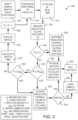
- FIG. 2 shows a flow chart 200 of the logic used by the feedback loop to determine whether the detection cell should automatically switch the position of a valve, e.g., valve 115 of FIGS. 1A-B .
- the process begins by injecting a sample (step 205) into a mobile phase flow stream of a chromatography system, for example, a liquid chromatography or gas chromatography system, creating a combined flow stream. If the valve (as described in FIGs. 1A and 1B ) is not already in Position A, then the valve is switched to Position A.
- the detection cell continuously monitors the peaks, for example, by UV detection (step 210 ).
- the detection cell fits the peaks in real time (step 215 ) and measures the resolution (R s ) and the peak width (w) (step 220 ) of the separated sample.
- the feedback loop then makes a first determination based on the measurements and calculations of the detector.
- the first determination is whether the measured resolution (R s ) is greater than a desired resolution (r D ) (step 225 ).
- the desired resolution (r D ) is a resolution value that has been pre-determined by the user as being a sufficient resolution for the separation of the sample. If it is determined that the measured resolution (R s ) is greater than a desired resolution (r D ) (step 225 ), then sufficient resolution has been achieved and the detection cell can calculate the elution time for each peak that has been separated from the sample (step 230 ) .
- a program fraction collector can collect each peak separately (step 235 ) and the method has been completed.
- the method includes detecting the combined flow stream by a detector that is located downstream of the at least two chromatographic columns.
- the detector can be, for example, a UV detection cell or a fluorescence detector.
- the feedback loop determines whether the measured combined peak width (w) is greater than or equal to a maximum combined peak width (w max ) (step 245 ).
- the maximum combined peak width is a predetermined maximum based on the specific sample that is being separated. In other words, the detector records the time at which the separation zone is fully eluted from the first column and sends a command to the valve to actuate at that moment in time. The same feedback control is repeated and ends when the front part of the sample zone is leaving one column which the rear part of the sample zone is still eluting from another column.
- a data processor in a feedback loop that can be incorporated into the detector determines whether a partial separation of the peaks can be collected (step 255 ). If a partial separation of the peaks can be collected (step 255 ), then the program fraction collection can collect each partially separated peak (step 235 ), a new sample can be injected (step 240 ) and the process can start again. If a partial separation of the peaks cannot be collected (step 255 ), the sample is dumped to waste (step 260 ), a new sample can be injected (step 240 ) and the process can start again.
- the feedback loop incorporated into the detection cell determines whether the switch count (s) is greater than or equal to a predetermined maximum number of switches (s max ) (step 265 ).
- the predetermined maximum number of switches is determined based on the specific sample to be separated.
- a data processor in a feedback loop determines whether a partial separation of the peaks can be collected (step 255 ). If a partial separation of the peaks can be collected (step 255 ), then the program fraction collection can collect each partially separated peak (step 235 ), a new sample can be injected (step 240 ) and the process can start again. If a partial separation of the peaks cannot be collected (step 255 ), the sample is dumped to waste (step 260 ), a new sample can be injected (step 240 ) and the process can start again.
- the switch time is calculated (step 270 ).
- the switch time is the time at which the detection cell will switch the valve from Position A to Position B or vice versa (see, e.g., FIGs. 1A and 1B ) .
- the detection cell will then execute the switch (step 275) at the calculated time by switching the valve from Position A to Position B or from Position B to Position A.
- the process then repeats with the continuation monitoring of the peaks (step 210 ), fitting the peaks in real time (step 215 ), and measuring the resolution and peak width (step 220 ) to determine whether the results of the separation are sufficient (step 230 ), no more resolution is possible (step 250 ) or whether the process needs to repeat again (steps 270, 275, 280 ).
- the feedback loop can determine whether (1) the measured resolution (R s ) is less than a desired resolution (r D ) (step 225 ); (2) the measured combined peak width (w) is less than a maximum combined peak width (w max ) (step 245 ); and (3) the switch count (s) is less than a predetermined maximum number of switches (s max ) (step 265 ), simultaneously.
- two steps can be performed simultaneously and then the third step can be performed.
- the steps can be performed in any order, for example step 245 can be performed first, then step 225, then step 265.
- step 265 can be performed first, then step 245, then step 225.
- the algorithm only includes two out of the three steps, for example, the algorithm can include steps 225 and 245, or steps 245 and 265, or steps 225 and 265.
- the feedback loop is in communication with a controller that controls the position of the valve.
- the controller can be located in the detection cell or the controller can be located with the circuitry (e.g., a microprocessor) of the feedback loop that is housed in a separate component from the detector cell (e.g., in a component located between the detector cell and the valve).
- the controller is in communication with the feedback loop, the valve, and the detection cell.
- a computer is coupled to the output of the detection cell.
- the computer has code executing thereof, which, when executed, causes the computer perform the recycling chromatography method described herein, i.e., monitoring chromatographic peaks of the sample as output by the detection cell, measuring resolution and width of the chromatographic peaks, and causing the controller to automatically switch the valve from a first position to a second position when the measured resolution is less than a desired resolution, the measured combined peak width is less than a maximum combined peak width, and a switch count is less than a predetermined maximum number of switches.
- the computer can store the data in memory.
- a non-transitory computer readable medium can include code stored thereof for executing the recycling chromatography method described herein.
Landscapes
- Chemical & Material Sciences (AREA)
- Analytical Chemistry (AREA)
- Life Sciences & Earth Sciences (AREA)
- Health & Medical Sciences (AREA)
- Physics & Mathematics (AREA)
- Biochemistry (AREA)
- General Health & Medical Sciences (AREA)
- General Physics & Mathematics (AREA)
- Immunology (AREA)
- Pathology (AREA)
- Chemical Kinetics & Catalysis (AREA)
- Sustainable Development (AREA)
- Treatment Of Liquids With Adsorbents In General (AREA)
Claims (14)
- Procédé de chromatographie de recyclage comprenant les étapes suivantes :
l'injection d'un échantillon dans un flux de phase mobile d'un système de chromatographie liquide (100) pour créer un flux combiné ; le système de chromatographie liquide comprenant :une première colonne chromatographique (110) et une seconde colonne chromatographique (120) placées en série ;une vanne (105) en communication fluidique avec la première colonne chromatographique et la seconde colonne chromatographique, la vanne ayant une première position de fonctionnement et une seconde position de fonctionnement ;une cellule de détection (115) en communication fluidique avec la première colonne chromatographique et la seconde colonne chromatographique et placée entre elles ; etun dispositif de commande qui commande la position de la vanne ;dans lequel lorsque la vanne est dans la première position, la production de la première colonne chromatographique passe à travers la vanne dans la cellule de détection et la production de la cellule de détection passe à travers la vanne et dans la seconde colonne chromatographique ; etlorsque la vanne est dans la seconde position, la production de la seconde colonne chromatographique passe à travers la vanne dans la cellule de détection et la production de la cellule de détection passe à travers la vanne et dans la première colonne chromatographique,faisant s'écouler le flux combiné à travers la première et la seconde colonne chromatographique ; etsurveillant les pics chromatographiques de l'échantillon avec un ordinateur couplé à la cellule de détection, dans lequel l'ordinateur mesure la résolution et la largeur des pics chromatographiques et amène le dispositif de commande à commuter automatiquement la vanne de la première position à la seconde position lorsque la résolution mesurée est inférieure à une résolution souhaitée, la largeur de pic combinée mesurée est inférieure à une largeur de pic combinée maximale et que le nombre de commutations est inférieur à un nombre maximal de commutations prédéterminé. - Procédé de chromatographie de recyclage selon la revendication 1, dans lequel l'ordinateur est configuré pour calculer un temps de commutation et amener le dispositif de commande à commuter automatiquement la vanne de la première position à la seconde position au temps de commutation calculé.
- Procédé de chromatographie de recyclage selon la revendication 1, dans lequel l'ordinateur continue à surveiller les pics chromatographiques de l'échantillon et à amener le dispositif de commande à commuter la vanne de la première position à la seconde position ou de la seconde position à la première position, jusqu'à ce quea) la résolution mesurée soit supérieure à la résolution souhaitée ;b) la largeur de pic combinée mesurée soit supérieure ou égale à la largeur de pic combinée maximale ; ouc) le nombre de commutations soit supérieur ou égal au nombre maximal de commutations prédéterminé.
- Procédé de chromatographie de recyclage selon la revendication 3, comprenant en outre la détection du flux combiné.
- Procédé de chromatographie de recyclage selon la revendication 3, comprenant en outre le calcul d'un temps d'élution pour chaque pic.
- Procédé de chromatographie de recyclage selon la revendication 1, dans lequel la cellule de détection est une cellule de détection à faible dispersion.
- Procédé de chromatographie de recyclage selon la revendication 1, dans lequel la première colonne chromatographique et la seconde colonne chromatographique sont identiques.
- Procédé de chromatographie de recyclage selon la revendication 1, dans lequel la vanne est une vanne à six orifices ou à huit orifices.
- Système de chromatographie en phase liquide (100) comprenant :un injecteur pour l'injection d'un échantillon dans un flux de phase mobile créant un flux combiné ;une première colonne chromatographique (110) et une seconde colonne chromatographique (120) placées en série et en aval de l'injecteur ;une vanne (105) en communication fluidique avec la première colonne chromatographique et la seconde colonne chromatographique, la vanne ayant une première position de fonctionnement et une seconde position de fonctionnement ;une cellule de détection (115) en communication fluidique avec la première colonne chromatographique et la seconde colonne chromatographique et placée entre elles,un dispositif de commande configuré pour commander la position de la vanne entre la première et la seconde position de fonctionnement ;caractérisé par un ordinateur en communication avec la cellule de détection et le dispositif de commande, dans lequel l'ordinateur est configuré pour :surveiller les pics chromatographiques de l'échantillon ;mesurer la résolution et la largeur des pics chromatographiques ; etamener le dispositif de commande à commuter automatiquement la vanne de la première à la seconde position lorsque la résolution mesurée est inférieure à une résolution souhaitée, la largeur de pic combinée mesurée est inférieure à une largeur de pic combinée maximale et le nombre de commutation est inférieur à un nombre maximal de commutations prédéterminé ;dans lequel lorsque la vanne est dans la première position, la production de la première colonne chromatographique passe à travers la vanne dans la cellule de détection et la production de la cellule de détection passe à travers la vanne et dans la seconde colonne chromatographique ; etlorsque la vanne est dans la seconde position, la production de la seconde colonne chromatographique passe à travers la vanne dans la cellule de détection et la production de la cellule de détection passe à travers la vanne et dans la première colonne chromatographique.
- Système de chromatographie selon la revendication 9, dans lequel l'ordinateur est en outre configuré pour calculer un temps de commutation et amener le dispositif de commande à commuter automatiquement la vanne de la première à la seconde position au temps de commutation calculé.
- Système de chromatographie selon la revendication 9, dans lequel la cellule de détection est une cellule de détection à faible dispersion.
- Système de chromatographie selon la revendication 9, dans lequel la première colonne chromatographique et la seconde colonne chromatographique sont identiques.
- Système de chromatographie selon la revendication 9, dans lequel la vanne est une vanne à six orifices ou à huit orifices.
- Système de chromatographie selon la revendication 9, dans lequel la première colonne chromatographique et la seconde colonne chromatographique sont des colonnes de chromatographie liquide.
Applications Claiming Priority (2)
| Application Number | Priority Date | Filing Date | Title |
|---|---|---|---|
| US201862649803P | 2018-03-29 | 2018-03-29 | |
| PCT/IB2019/052566 WO2019186469A1 (fr) | 2018-03-29 | 2019-03-28 | Procédé de chromatographie de recyclage à deux colonnes automatisé pour le déverrouillage de problèmes de séparation difficiles |
Publications (2)
| Publication Number | Publication Date |
|---|---|
| EP3773968A1 EP3773968A1 (fr) | 2021-02-17 |
| EP3773968B1 true EP3773968B1 (fr) | 2025-02-26 |
Family
ID=66542456
Family Applications (1)
| Application Number | Title | Priority Date | Filing Date |
|---|---|---|---|
| EP19724232.4A Active EP3773968B1 (fr) | 2018-03-29 | 2019-03-28 | Procédé de chromatographie de recyclage à deux colonnes automatisé pour la résolution de problèmes de séparation difficiles |
Country Status (4)
| Country | Link |
|---|---|
| US (1) | US20190302067A1 (fr) |
| EP (1) | EP3773968B1 (fr) |
| CN (1) | CN111902196A (fr) |
| WO (1) | WO2019186469A1 (fr) |
Families Citing this family (1)
| Publication number | Priority date | Publication date | Assignee | Title |
|---|---|---|---|---|
| CN112946144B (zh) * | 2021-03-26 | 2025-07-08 | 苏州赛谱仪器有限公司 | 一种基于四柱选择阀的进样层析装置及其进样控制方法 |
Family Cites Families (15)
| Publication number | Priority date | Publication date | Assignee | Title |
|---|---|---|---|---|
| US4274967A (en) * | 1978-07-07 | 1981-06-23 | Technicon Instruments Corporation | Chromatographic apparatus and method |
| JPS56140234A (en) * | 1980-04-04 | 1981-11-02 | Hitachi Ltd | Liquid sampling device |
| US4724081A (en) * | 1986-04-28 | 1988-02-09 | Soken Kagaku Kabushiki Kaisha | Process and apparatus for separation by liquid chromatography |
| US5071547A (en) * | 1990-03-23 | 1991-12-10 | Separations Technology, Inc. | Column chromatographic column apparatus with switching capability |
| US5958227A (en) * | 1997-07-15 | 1999-09-28 | Tosoh Corporation | Liquid chromatograph apparatus with a switching valve |
| CN1296708C (zh) * | 2001-06-15 | 2007-01-24 | 中国科学院大连化学物理研究所 | 一种手性药物分离用双柱切换色谱制备装置 |
| JP5140721B2 (ja) * | 2007-04-17 | 2013-02-13 | イクスエンド、ホールディング、ベスローテン、フェンノートシャップ | 連続メンブレン吸着方法および装置 |
| US8322189B2 (en) * | 2008-08-29 | 2012-12-04 | Exxonmobil Research And Engineering Company | Comprehensive two-dimensional gas chromatography method with one switching valve as the modulator |
| US20110232373A1 (en) * | 2008-12-04 | 2011-09-29 | Vrije Universiteit Brussel | Chromatographic separation device with variable length and a method for its use |
| US8459302B2 (en) * | 2009-09-21 | 2013-06-11 | Gulf Sea Ventures LLC | Fluid-directing multiport rotary valve |
| CN104614458B (zh) * | 2015-01-21 | 2016-06-22 | 柳仁民 | 一种带多通阀的循环制备高效液相色谱仪 |
| CN104606921B (zh) * | 2015-01-21 | 2016-04-13 | 柳仁民 | 一种双柱循环制备高效液相色谱仪及用于制备分离纯化的方法 |
| CN204925057U (zh) * | 2015-09-07 | 2015-12-30 | 浙江省质量检测科学研究院 | 基于色谱柱切换技术的柱切换时间参数的测定装置 |
| CN106198800A (zh) * | 2016-07-08 | 2016-12-07 | 中国石油化工股份有限公司 | 基于流动渗析离子色谱法检测腈纶溶剂中阴离子的装置及检测方法 |
| CN107703241A (zh) * | 2017-11-06 | 2018-02-16 | 福建和盛高科技产业有限公司 | 用于油气色谱在线监测检测的六通阀结构及其使用方法 |
-
2019
- 2019-03-28 EP EP19724232.4A patent/EP3773968B1/fr active Active
- 2019-03-28 CN CN201980023679.7A patent/CN111902196A/zh active Pending
- 2019-03-28 WO PCT/IB2019/052566 patent/WO2019186469A1/fr not_active Ceased
- 2019-03-28 US US16/367,566 patent/US20190302067A1/en not_active Abandoned
Non-Patent Citations (1)
| Title |
|---|
| FABRICE GRITTI ET AL: "Ideal versus real automated twin column recycling chromatography process", JOURNAL OF CHROMATOGRAPHY A, vol. 1508, 1 July 2017 (2017-07-01), AMSTERDAM, NL, pages 81 - 94, XP055599390, ISSN: 0021-9673, DOI: 10.1016/j.chroma.2017.06.009 * |
Also Published As
| Publication number | Publication date |
|---|---|
| CN111902196A (zh) | 2020-11-06 |
| WO2019186469A1 (fr) | 2019-10-03 |
| EP3773968A1 (fr) | 2021-02-17 |
| US20190302067A1 (en) | 2019-10-03 |
Similar Documents
| Publication | Publication Date | Title |
|---|---|---|
| AU661349B2 (en) | Protein chromatography system | |
| EP2689244B1 (fr) | Soupape et système de séparation pour analyse de liquide multidimensionnelle | |
| US8992778B2 (en) | Methods and apparatus for generating solvent gradients in liquid chromatography | |
| Gritti et al. | Semi-preparative high-resolution recycling liquid chromatography | |
| Kromidas | The HPLC expert II: Find and optimize the benefits of your HPLC/UHPLC | |
| US5801302A (en) | Multicycle loop injection for trace analysis by ion chomatography apparatus and method | |
| Alexander et al. | Modifying conventional high-performance liquid chromatography systems to achieve fast separations with fused-core columns: a case study | |
| Jongenotter et al. | Automated On‐Line GPC‐GC‐FPD Involving Co‐Solvent Trapping and the On‐Column Interface for the Determination of Organophosphorus Pesticides in Olive Oils | |
| US11099159B2 (en) | Systems, methods and devices for reducing band dispersion in chromatography | |
| EP3773968B1 (fr) | Procédé de chromatographie de recyclage à deux colonnes automatisé pour la résolution de problèmes de séparation difficiles | |
| EP4065971B1 (fr) | Injection d'échantillon pour chromatographie liquide utilisant un flux de solvant divisé | |
| AU2006292446A1 (en) | IC system including sample pretreatment and using a single pump | |
| US12013380B2 (en) | System and method for controlling fluid flow within a liquid chromatography system | |
| US12078621B2 (en) | Automated semi-preparative gradient recycling liquid chromatography | |
| JP5076807B2 (ja) | マルチディメンジョナルガスクロマトグラフ装置 | |
| Chibério et al. | Batch chromatography with recycle lag. II—Physical realization and experimental validation | |
| JPH02253155A (ja) | 分取クロマトグラフィ及びその装置 | |
| Kromidas | When Should I Use My UHPLC as a UHPLC? | |
| Mahler et al. | Multi-column systems in gas chromatography | |
| Letter | Automated column selection and switching systems for HPLC | |
| JPH0375069B2 (fr) | ||
| Dolphin et al. | Band-Broadening Effects in a Column-Switching System for HPLC | |
| Xu et al. | Analysis of alkylbenzene samples by comprehensive capillary liquid chromatography× capillary gas chromatography | |
| Schoenmakers | Programmed analysis | |
| GB2471956A (en) | Device for performing chromatographic separations |
Legal Events
| Date | Code | Title | Description |
|---|---|---|---|
| STAA | Information on the status of an ep patent application or granted ep patent |
Free format text: STATUS: UNKNOWN |
|
| STAA | Information on the status of an ep patent application or granted ep patent |
Free format text: STATUS: THE INTERNATIONAL PUBLICATION HAS BEEN MADE |
|
| PUAI | Public reference made under article 153(3) epc to a published international application that has entered the european phase |
Free format text: ORIGINAL CODE: 0009012 |
|
| STAA | Information on the status of an ep patent application or granted ep patent |
Free format text: STATUS: REQUEST FOR EXAMINATION WAS MADE |
|
| 17P | Request for examination filed |
Effective date: 20200916 |
|
| AK | Designated contracting states |
Kind code of ref document: A1 Designated state(s): AL AT BE BG CH CY CZ DE DK EE ES FI FR GB GR HR HU IE IS IT LI LT LU LV MC MK MT NL NO PL PT RO RS SE SI SK SM TR |
|
| AX | Request for extension of the european patent |
Extension state: BA ME |
|
| DAV | Request for validation of the european patent (deleted) | ||
| DAX | Request for extension of the european patent (deleted) | ||
| STAA | Information on the status of an ep patent application or granted ep patent |
Free format text: STATUS: EXAMINATION IS IN PROGRESS |
|
| 17Q | First examination report despatched |
Effective date: 20230525 |
|
| GRAP | Despatch of communication of intention to grant a patent |
Free format text: ORIGINAL CODE: EPIDOSNIGR1 |
|
| STAA | Information on the status of an ep patent application or granted ep patent |
Free format text: STATUS: GRANT OF PATENT IS INTENDED |
|
| INTG | Intention to grant announced |
Effective date: 20240718 |
|
| GRAJ | Information related to disapproval of communication of intention to grant by the applicant or resumption of examination proceedings by the epo deleted |
Free format text: ORIGINAL CODE: EPIDOSDIGR1 |
|
| STAA | Information on the status of an ep patent application or granted ep patent |
Free format text: STATUS: EXAMINATION IS IN PROGRESS |
|
| GRAP | Despatch of communication of intention to grant a patent |
Free format text: ORIGINAL CODE: EPIDOSNIGR1 |
|
| STAA | Information on the status of an ep patent application or granted ep patent |
Free format text: STATUS: GRANT OF PATENT IS INTENDED |
|
| INTC | Intention to grant announced (deleted) | ||
| INTG | Intention to grant announced |
Effective date: 20241205 |
|
| GRAS | Grant fee paid |
Free format text: ORIGINAL CODE: EPIDOSNIGR3 |
|
| GRAA | (expected) grant |
Free format text: ORIGINAL CODE: 0009210 |
|
| STAA | Information on the status of an ep patent application or granted ep patent |
Free format text: STATUS: THE PATENT HAS BEEN GRANTED |
|
| AK | Designated contracting states |
Kind code of ref document: B1 Designated state(s): AL AT BE BG CH CY CZ DE DK EE ES FI FR GB GR HR HU IE IS IT LI LT LU LV MC MK MT NL NO PL PT RO RS SE SI SK SM TR |
|
| P01 | Opt-out of the competence of the unified patent court (upc) registered |
Free format text: CASE NUMBER: APP_3379/2025 Effective date: 20250121 |
|
| REG | Reference to a national code |
Ref country code: GB Ref legal event code: FG4D |
|
| REG | Reference to a national code |
Ref country code: CH Ref legal event code: EP |
|
| REG | Reference to a national code |
Ref country code: DE Ref legal event code: R096 Ref document number: 602019066472 Country of ref document: DE |
|
| REG | Reference to a national code |
Ref country code: IE Ref legal event code: FG4D |
|
| REG | Reference to a national code |
Ref country code: NL Ref legal event code: MP Effective date: 20250226 |
|
| PG25 | Lapsed in a contracting state [announced via postgrant information from national office to epo] |
Ref country code: RS Free format text: LAPSE BECAUSE OF FAILURE TO SUBMIT A TRANSLATION OF THE DESCRIPTION OR TO PAY THE FEE WITHIN THE PRESCRIBED TIME-LIMIT Effective date: 20250526 |
|
| PG25 | Lapsed in a contracting state [announced via postgrant information from national office to epo] |
Ref country code: FI Free format text: LAPSE BECAUSE OF FAILURE TO SUBMIT A TRANSLATION OF THE DESCRIPTION OR TO PAY THE FEE WITHIN THE PRESCRIBED TIME-LIMIT Effective date: 20250226 |
|
| PG25 | Lapsed in a contracting state [announced via postgrant information from national office to epo] |
Ref country code: PL Free format text: LAPSE BECAUSE OF FAILURE TO SUBMIT A TRANSLATION OF THE DESCRIPTION OR TO PAY THE FEE WITHIN THE PRESCRIBED TIME-LIMIT Effective date: 20250226 |
|
| PG25 | Lapsed in a contracting state [announced via postgrant information from national office to epo] |
Ref country code: ES Free format text: LAPSE BECAUSE OF FAILURE TO SUBMIT A TRANSLATION OF THE DESCRIPTION OR TO PAY THE FEE WITHIN THE PRESCRIBED TIME-LIMIT Effective date: 20250226 |
|
| REG | Reference to a national code |
Ref country code: LT Ref legal event code: MG9D |
|
| PG25 | Lapsed in a contracting state [announced via postgrant information from national office to epo] |
Ref country code: IS Free format text: LAPSE BECAUSE OF FAILURE TO SUBMIT A TRANSLATION OF THE DESCRIPTION OR TO PAY THE FEE WITHIN THE PRESCRIBED TIME-LIMIT Effective date: 20250626 Ref country code: NO Free format text: LAPSE BECAUSE OF FAILURE TO SUBMIT A TRANSLATION OF THE DESCRIPTION OR TO PAY THE FEE WITHIN THE PRESCRIBED TIME-LIMIT Effective date: 20250526 |
|
| PG25 | Lapsed in a contracting state [announced via postgrant information from national office to epo] |
Ref country code: NL Free format text: LAPSE BECAUSE OF FAILURE TO SUBMIT A TRANSLATION OF THE DESCRIPTION OR TO PAY THE FEE WITHIN THE PRESCRIBED TIME-LIMIT Effective date: 20250226 |
|
| PG25 | Lapsed in a contracting state [announced via postgrant information from national office to epo] |
Ref country code: HR Free format text: LAPSE BECAUSE OF FAILURE TO SUBMIT A TRANSLATION OF THE DESCRIPTION OR TO PAY THE FEE WITHIN THE PRESCRIBED TIME-LIMIT Effective date: 20250226 |
|
| PG25 | Lapsed in a contracting state [announced via postgrant information from national office to epo] |
Ref country code: PT Free format text: LAPSE BECAUSE OF FAILURE TO SUBMIT A TRANSLATION OF THE DESCRIPTION OR TO PAY THE FEE WITHIN THE PRESCRIBED TIME-LIMIT Effective date: 20250626 Ref country code: LV Free format text: LAPSE BECAUSE OF FAILURE TO SUBMIT A TRANSLATION OF THE DESCRIPTION OR TO PAY THE FEE WITHIN THE PRESCRIBED TIME-LIMIT Effective date: 20250226 |
|
| PG25 | Lapsed in a contracting state [announced via postgrant information from national office to epo] |
Ref country code: GR Free format text: LAPSE BECAUSE OF FAILURE TO SUBMIT A TRANSLATION OF THE DESCRIPTION OR TO PAY THE FEE WITHIN THE PRESCRIBED TIME-LIMIT Effective date: 20250527 Ref country code: BG Free format text: LAPSE BECAUSE OF FAILURE TO SUBMIT A TRANSLATION OF THE DESCRIPTION OR TO PAY THE FEE WITHIN THE PRESCRIBED TIME-LIMIT Effective date: 20250226 |
|
| REG | Reference to a national code |
Ref country code: AT Ref legal event code: MK05 Ref document number: 1770098 Country of ref document: AT Kind code of ref document: T Effective date: 20250226 |
|
| PG25 | Lapsed in a contracting state [announced via postgrant information from national office to epo] |
Ref country code: SE Free format text: LAPSE BECAUSE OF FAILURE TO SUBMIT A TRANSLATION OF THE DESCRIPTION OR TO PAY THE FEE WITHIN THE PRESCRIBED TIME-LIMIT Effective date: 20250226 |
|
| PG25 | Lapsed in a contracting state [announced via postgrant information from national office to epo] |
Ref country code: SM Free format text: LAPSE BECAUSE OF FAILURE TO SUBMIT A TRANSLATION OF THE DESCRIPTION OR TO PAY THE FEE WITHIN THE PRESCRIBED TIME-LIMIT Effective date: 20250226 |
|
| PG25 | Lapsed in a contracting state [announced via postgrant information from national office to epo] |
Ref country code: DK Free format text: LAPSE BECAUSE OF FAILURE TO SUBMIT A TRANSLATION OF THE DESCRIPTION OR TO PAY THE FEE WITHIN THE PRESCRIBED TIME-LIMIT Effective date: 20250226 |
|
| PG25 | Lapsed in a contracting state [announced via postgrant information from national office to epo] |
Ref country code: IT Free format text: LAPSE BECAUSE OF FAILURE TO SUBMIT A TRANSLATION OF THE DESCRIPTION OR TO PAY THE FEE WITHIN THE PRESCRIBED TIME-LIMIT Effective date: 20250226 |
|
| PG25 | Lapsed in a contracting state [announced via postgrant information from national office to epo] |
Ref country code: AT Free format text: LAPSE BECAUSE OF FAILURE TO SUBMIT A TRANSLATION OF THE DESCRIPTION OR TO PAY THE FEE WITHIN THE PRESCRIBED TIME-LIMIT Effective date: 20250226 |
|
| PG25 | Lapsed in a contracting state [announced via postgrant information from national office to epo] |
Ref country code: CZ Free format text: LAPSE BECAUSE OF FAILURE TO SUBMIT A TRANSLATION OF THE DESCRIPTION OR TO PAY THE FEE WITHIN THE PRESCRIBED TIME-LIMIT Effective date: 20250226 Ref country code: EE Free format text: LAPSE BECAUSE OF FAILURE TO SUBMIT A TRANSLATION OF THE DESCRIPTION OR TO PAY THE FEE WITHIN THE PRESCRIBED TIME-LIMIT Effective date: 20250226 |
|
| REG | Reference to a national code |
Ref country code: CH Ref legal event code: H13 Free format text: ST27 STATUS EVENT CODE: U-0-0-H10-H13 (AS PROVIDED BY THE NATIONAL OFFICE) Effective date: 20251023 |
|
| PG25 | Lapsed in a contracting state [announced via postgrant information from national office to epo] |
Ref country code: RO Free format text: LAPSE BECAUSE OF FAILURE TO SUBMIT A TRANSLATION OF THE DESCRIPTION OR TO PAY THE FEE WITHIN THE PRESCRIBED TIME-LIMIT Effective date: 20250226 |
|
| PG25 | Lapsed in a contracting state [announced via postgrant information from national office to epo] |
Ref country code: SK Free format text: LAPSE BECAUSE OF FAILURE TO SUBMIT A TRANSLATION OF THE DESCRIPTION OR TO PAY THE FEE WITHIN THE PRESCRIBED TIME-LIMIT Effective date: 20250226 |
|
| PG25 | Lapsed in a contracting state [announced via postgrant information from national office to epo] |
Ref country code: LU Free format text: LAPSE BECAUSE OF NON-PAYMENT OF DUE FEES Effective date: 20250328 |
|
| REG | Reference to a national code |
Ref country code: DE Ref legal event code: R097 Ref document number: 602019066472 Country of ref document: DE |
|
| REG | Reference to a national code |
Ref country code: BE Ref legal event code: MM Effective date: 20250331 |
|
| PG25 | Lapsed in a contracting state [announced via postgrant information from national office to epo] |
Ref country code: MC Free format text: LAPSE BECAUSE OF FAILURE TO SUBMIT A TRANSLATION OF THE DESCRIPTION OR TO PAY THE FEE WITHIN THE PRESCRIBED TIME-LIMIT Effective date: 20250226 |
|
| PLBE | No opposition filed within time limit |
Free format text: ORIGINAL CODE: 0009261 |
|
| STAA | Information on the status of an ep patent application or granted ep patent |
Free format text: STATUS: NO OPPOSITION FILED WITHIN TIME LIMIT |
|
| PG25 | Lapsed in a contracting state [announced via postgrant information from national office to epo] |
Ref country code: FR Free format text: LAPSE BECAUSE OF NON-PAYMENT OF DUE FEES Effective date: 20250426 |
|
| PG25 | Lapsed in a contracting state [announced via postgrant information from national office to epo] |
Ref country code: BE Free format text: LAPSE BECAUSE OF NON-PAYMENT OF DUE FEES Effective date: 20250331 |
|
| PG25 | Lapsed in a contracting state [announced via postgrant information from national office to epo] |
Ref country code: CH Free format text: LAPSE BECAUSE OF NON-PAYMENT OF DUE FEES Effective date: 20250331 |
|
| PG25 | Lapsed in a contracting state [announced via postgrant information from national office to epo] |
Ref country code: IE Free format text: LAPSE BECAUSE OF NON-PAYMENT OF DUE FEES Effective date: 20250328 |
|
| 26N | No opposition filed |
Effective date: 20251127 |
|
| PGFP | Annual fee paid to national office [announced via postgrant information from national office to epo] |
Ref country code: GB Payment date: 20260220 Year of fee payment: 8 |
|
| PGFP | Annual fee paid to national office [announced via postgrant information from national office to epo] |
Ref country code: DE Payment date: 20260219 Year of fee payment: 8 |