EP3774169B1 - Procédé de découpage des parties d'une pièce - Google Patents
Procédé de découpage des parties d'une pièce Download PDFInfo
- Publication number
- EP3774169B1 EP3774169B1 EP19712779.8A EP19712779A EP3774169B1 EP 3774169 B1 EP3774169 B1 EP 3774169B1 EP 19712779 A EP19712779 A EP 19712779A EP 3774169 B1 EP3774169 B1 EP 3774169B1
- Authority
- EP
- European Patent Office
- Prior art keywords
- workpiece
- support
- cutting
- support surface
- parts
- Prior art date
- Legal status (The legal status is an assumption and is not a legal conclusion. Google has not performed a legal analysis and makes no representation as to the accuracy of the status listed.)
- Active
Links
Images




Classifications
-
- B—PERFORMING OPERATIONS; TRANSPORTING
- B23—MACHINE TOOLS; METAL-WORKING NOT OTHERWISE PROVIDED FOR
- B23K—SOLDERING OR UNSOLDERING; WELDING; CLADDING OR PLATING BY SOLDERING OR WELDING; CUTTING BY APPLYING HEAT LOCALLY, e.g. FLAME CUTTING; WORKING BY LASER BEAM
- B23K37/00—Auxiliary devices or processes, not specially adapted for a procedure covered by only one of the other main groups of this subclass
- B23K37/04—Auxiliary devices or processes, not specially adapted for a procedure covered by only one of the other main groups of this subclass for holding or positioning work
- B23K37/0408—Auxiliary devices or processes, not specially adapted for a procedure covered by only one of the other main groups of this subclass for holding or positioning work for planar work
-
- B—PERFORMING OPERATIONS; TRANSPORTING
- B23—MACHINE TOOLS; METAL-WORKING NOT OTHERWISE PROVIDED FOR
- B23K—SOLDERING OR UNSOLDERING; WELDING; CLADDING OR PLATING BY SOLDERING OR WELDING; CUTTING BY APPLYING HEAT LOCALLY, e.g. FLAME CUTTING; WORKING BY LASER BEAM
- B23K10/00—Welding or cutting by means of a plasma
-
- B—PERFORMING OPERATIONS; TRANSPORTING
- B23—MACHINE TOOLS; METAL-WORKING NOT OTHERWISE PROVIDED FOR
- B23K—SOLDERING OR UNSOLDERING; WELDING; CLADDING OR PLATING BY SOLDERING OR WELDING; CUTTING BY APPLYING HEAT LOCALLY, e.g. FLAME CUTTING; WORKING BY LASER BEAM
- B23K26/00—Working by laser beam, e.g. welding, cutting or boring
- B23K26/08—Devices involving relative movement between laser beam and workpiece
- B23K26/083—Devices involving movement of the workpiece in at least one axial direction
- B23K26/0838—Devices involving movement of the workpiece in at least one axial direction by using an endless conveyor belt
-
- B—PERFORMING OPERATIONS; TRANSPORTING
- B23—MACHINE TOOLS; METAL-WORKING NOT OTHERWISE PROVIDED FOR
- B23K—SOLDERING OR UNSOLDERING; WELDING; CLADDING OR PLATING BY SOLDERING OR WELDING; CUTTING BY APPLYING HEAT LOCALLY, e.g. FLAME CUTTING; WORKING BY LASER BEAM
- B23K26/00—Working by laser beam, e.g. welding, cutting or boring
- B23K26/36—Removing material
- B23K26/38—Removing material by boring or cutting
Definitions
- the invention lies in the technical field of the separating machining of workpieces and relates to a method for cutting workpiece parts out of a plate-shaped workpiece by means of a cutting beam, see claim 1.
- a laser beam with sufficient energy to separate the metal is directed at a metal sheet and guided along the cutting contours of the metal parts to be cut out.
- the cutting points are controlled by a cutting head that can be moved over the metal sheet and the laser beam emerges from the nozzle at the end of the head.
- a variety of problems can arise that adversely affect the efficiency and costs of automated production of metal parts.
- a cut-out metal part can tilt relative to the remaining workpiece ("residual grid"), which is particularly the case with the frequently used workpiece supports with support tips. If a metal part tilts, a collision with the cutting head used further in the cutting process is possible. This interrupts the cutting process and, in the worst case, the cutting head is damaged. This can be avoided, for example, by packing the metal parts so low that the cutting head is always sufficiently far away from a possibly tilted neighboring metal part when cutting out a metal part.
- the disadvantages of this approach are the relatively poor material utilization and the associated higher production costs.
- microjoints residual grid
- DE102011054360 discloses a method for producing workpieces with a laser processing machine, with a workpiece support for receiving plate-shaped materials for processing with a separating device which has a processing head which can be moved at least in the Y direction in the plate-shaped material during a separating process, wherein the workpiece support comprises a first support table with a first support surface and a second support table with a second support surface, wherein the support surfaces are spaced apart from one another to form a gap below the processing head, and wherein the position of the gap and the width of the gap in the processing area of the separating process can be adjusted by positioning the support tables in the X direction relative to one another.
- the object of the present invention is to advantageously further develop conventional methods for cutting out workpiece parts from plate-shaped workpieces by means of a cutting beam in such a way that a production of workpiece parts with a particularly high process reliability and efficiency as well as relatively low production costs is possible.
- a method for cutting out workpiece parts from a plate-shaped workpiece by means of a cutting beam directed at the workpiece is shown.
- the method according to the invention can be carried out in a laser cutting machine in which workpiece parts are cut out of the plate-shaped workpiece by means of a laser beam.
- any technology in which a cutting beam is used to separate a workpiece can be used for the method according to the invention.
- plasma cutting and water jet cutting are suitable for this.
- a cutting beam is guided along respective cutting contours of the workpiece parts.
- the workpiece parts to be cut out from the same workpiece can have different shapes and different sizes from one another.
- the cutting beam is guided within an elongated cutting gap that is delimited by a workpiece support consisting of three separate support surfaces.
- the support surfaces are arranged one after the other in a row, i.e. have a row-like arrangement. In a direction perpendicular to the direction of the row-like arrangement of the support surfaces, there is only one support surface at a time.
- the cutting gap is limited by two immediately adjacent support surfaces, whereby the cutting gap extends perpendicular to the row-like arrangement of the support surfaces and is completely open. Immediately adjacent support surfaces are typically separated from one another by a gap.
- the cutting gap has a longer dimension along its extension and a shorter dimension perpendicular to this.
- the shorter dimension in the direction of the row-like arrangement of the support surfaces is referred to as the "cutting gap width”.
- the longer dimension (extension of the cutting gap) perpendicular to the direction of the row-like arrangement of the support surfaces is referred to as the "cutting gap length”.
- the plate-shaped workpiece is provided on a workpiece support consisting of three support surfaces, whereby the cutting gap is formed by two immediately adjacent support surfaces, whereby the support surface which is immediately adjacent to the cutting gap and is arranged between two other support surfaces is a height-adjustable support surface.
- the cutting gap is thus formed by a height-adjustable support surface and an immediately adjacent support surface which is height-adjustable or alternatively has a fixed position relative to the external environment (i.e. not height-adjustable) is directly delimited or formed.
- the cutting gap extends perpendicular to the direction of the row-like arrangement of the support surfaces or support tables (cutting gap length).
- the cutting gap width is measured in the direction of the row-like arrangement of the support surfaces, i.e. perpendicular to the cutting gap length. Typically, the cutting gap length is greater than the cutting gap width.
- the cutting gap is delimited over the entire cutting gap length by two immediately adjacent support surfaces, wherein it is in accordance with the invention if, based on the direction of the sequence of support surfaces, on one side of the cutting gap there is a single height-adjustable support surface (which directly delimits the cutting gap) and on the other, opposite side of the cutting gap there is either a single height-adjustable support surface or alternatively a single non-height-adjustable support surface (which also directly delimits the cutting gap). Accordingly, exactly one height-adjustable support surface borders the cutting gap along the entire cutting gap length on one side and/or the other side of the cutting gap.
- the cutting gap has a constant width over the entire cutting gap length.
- the cutting gap typically has a rectangular shape.
- the cutting gap preferably extends over the respective complete widths (width is the dimension perpendicular to the direction of the row-like arrangement of the support surface) of the two immediately adjacent support surfaces that delimit the cutting gap.
- widths of the two immediately adjacent support surfaces or support tables are preferably the same. The two immediately adjacent support surfaces thus form a cutting gap over their respective complete width.
- the cutting gap formed by two immediately adjacent support surfaces is open along the entire cutting gap length and along the entire cutting gap width, i.e. the workpiece support has a breakthrough (opening) in the cutting gap, the extent of which extends over the entire cutting gap length and the entire cutting gap width.
- the cutting gap is therefore not only partially open, but is completely open between the two immediately adjacent (cutting gap-forming) support surfaces.
- the cutting gap between the two immediately adjacent support surfaces is completely open and therefore has no further support surface within the cutting gap.
- a cut-out workpiece part is removed from the residual grid by lowering it onto a height-adjustable support surface that initially serves as part of the workpiece support, whereby the workpiece part can be easily, reliably and quickly ejected immediately after cutting free. As soon as the workpiece part is lowered, a collision with the cutting head is no longer possible. While the height-adjustable support surface is lowered, the other support surfaces, which are arranged on both sides of the cutting gap, continue to form a workpiece support for the plate-shaped workpiece or residual grid, so that the cutting process can be continued.
- a Cutting process is carried out or continued to cut out at least one further workpiece part. This allows workpiece parts to be manufactured with a particularly high level of efficiency.
- the workpiece part removed from the residual grid by lowering the height-adjustable support surface can in principle be of any size that allows it to be lowered onto the at least one height-adjustable support surface.
- very efficient parts production can be achieved.
- the at least one height-adjustable support surface is designed to be tiltable in the low position, whereby the workpiece part located on the support surface slides off the support surface when the support surface is tilted and ends up in a good part container, for example.
- the workpiece part is transferred from the support surface in the low position to a (workpiece part) removal device for removing the workpiece part and is then transported away.
- the workpiece part can be transferred to the workpiece part removal device, for example, by tilting the height-adjustable support surface in the low position, i.e. the workpiece part slips off.
- actively driven transport of the workpiece part e.g. belt transport
- the rapid freeing of the height-adjustable support surface enables rapid return to the plane of the workpiece support in order to remove further workpiece parts from the residual skeleton by lowering the support surface, which further improves the efficiency of part production.
- the workpiece part is transported by the workpiece part removal device to a position in which the workpiece part is located outside a space that is located (directly) below the workpiece support in the direction of gravity. This measure ensures that the workpiece part is easily accessible, particularly from above, and can be easily removed from the workpiece part removal device, for example by a handling device such as a suction lifter.
- the at least one height-adjustable support surface is adjusted between the high position and the at least one low position by adjusting the height of a support table forming the support surface.
- This enables the height of the support surface to be adjusted particularly easily.
- the support surface is fixed in position relative to a base of the support table.
- the support surface is additionally or alternatively adjusted relative to the base of the support table.
- At least one workpiece part is cut out of the plate-shaped workpiece in such a way that it falls through the cutting gap when it is cut free.
- the workpiece part must have a suitable size, i.e. it must have a dimension in the direction of the gap width that is smaller than the gap width.
- small workpiece parts can be easily, quickly and reliably discharged through the cutting gap, thereby improving the efficiency of part production.
- small workpiece parts and/or small waste parts falling through the cutting gap are diverted from the fall line, in particular into a corresponding good part or waste part container. It is conceivable that different workpiece parts and/or waste parts falling through the cutting gap are diverted in different directions from one another, in particular in order to sort workpiece parts and/or waste parts. Preferably, small waste parts falling through the cutting gap (directly) reach a waste part removal device and are transported away, for example to a waste part container.
- At least one workpiece part is removed from the residual skeleton by picking up the workpiece part by means of a handling device, for example a suction lifter, and removing it from the residual skeleton.
- a handling device for example a suction lifter
- only such workpiece parts in this way, removed from the residual grid which, measured in the direction of the gap width of the cutting gap (ie in the direction of the row-like arrangement of the support surfaces), each have a dimension which is equal to or greater than the sum of a dimension of the at least one height-adjustable support surface and the gap width of the cutting gap.
- the options shown for removing workpiece parts of different sizes can be combined as desired.
- Small workpiece parts preferably exclusively
- the rapid removal of small and medium-sized workpiece parts that have already been cut out can significantly reduce the problems described at the beginning due to the possible tilting of workpiece parts relative to the residual skeleton and the associated risk of collision with the cutting head.
- the plate-shaped workpiece is fully supported by the support surfaces that form the workpiece support.
- at least one cut-out workpiece part and/or the residual skeleton is fixed to at least one support surface, in particular the entire workpiece support.
- a workpiece part to be ejected is advantageously fixed to the height-adjustable support surface in order to ensure stable support while the support surface is lowered from the high position to the at least one low position.
- the device for cutting out workpiece parts comprises three level separate support surfaces that are arranged one after the other in a row.
- the support surfaces are each formed by a separate support table, each support table having a flat support surface that is different from the support surface of another support table. Objects can be brought to rest on the support surfaces by their own weight.
- the flat support surfaces are each arranged in such a way that a perpendicular to the support surface includes at least one directional component that is directed upwards against gravity.
- the flat support surfaces are each arranged horizontally, with the perpendiculars to the support surfaces directed upwards against gravity.
- the device is designed in such a way that there is a sufficiently large gap between two immediately adjacent support surfaces that can serve as a cutting gap for the cutting beam.
- two immediately adjacent support tables that form the two support surfaces are arranged with a spacing between them so that a gap is formed between the associated support surfaces that serves as a cutting gap for the cutting beam.
- the device is designed in such a way that the plate-shaped workpiece can only be machined by means of the cutting beam in the area of the cutting gap.
- a flat workpiece support for the plate-shaped workpiece is formed by two support surfaces that are arranged on both sides (i.e. on opposite sides) of the cutting gap.
- the term "workpiece support” refers to support surfaces that are aligned with one another and thus arranged in the same plane. It is understood that the workpiece support can equally be formed by three support surfaces.
- the workpiece support which is therefore always composed of at least two support surfaces, is typically formed in a horizontal plane.
- the plate-shaped workpiece (or the residual grid after cutting out at least one workpiece part) can be arranged on the workpiece support in such a way that a freely selectable section of the workpiece can be positioned above the cutting gap in order to subject this section to separating processing by the cutting beam.
- a freely ending edge section of the workpiece can thus be positioned above the cutting gap or the workpiece spans the cutting gap and rests on at least two support surfaces that are arranged on both sides of the cutting gap at the same time, so that a further inside Section of the workpiece can be processed by the cutting beam.
- a support surface which is immediately adjacent to the cutting gap and is arranged between two other support surfaces is a height-adjustable support surface.
- the height of the support surface is adjustable between a high position in which the support surface contributes to the workpiece support and is arranged in the plane of the workpiece support, and at least one freely selectable low position in which the support surface is lowered relative to the workpiece support (relative to the plane of the support surfaces which together form the workpiece support).
- a support table forming the height-adjustable support surface is itself height-adjustable for this purpose, whereby adjusting the height of the support table simultaneously adjusts the height of its support surface between the high position and the at least one low position.
- a relative position of the support surface to a base of the support table which carries the support surface advantageously remains unchanged.
- the height of the base of the support table supporting the support surface remains unchanged and only the height of the support surface is changed in order to adjust the support surface between the high position and at least one low position. In the latter case, the relative position between the base of the support table supporting the support surface and the support surface changes.
- the term "height" refers to a position of a support surface or of the support table forming the support surface in relation to the direction of gravity, with a low position in the direction of gravity being below a high position and a high position against the direction of gravity being above a low position.
- the height-adjustable support surface can thus be brought into at least one low position by lowering in the direction of gravity from the high position and into the high position by raising against the direction of gravity from a low position.
- lowering comprises at least one movement component in the direction of gravity
- raising comprises at least one movement component against the direction of gravity.
- the support surface and/or the support table must be equipped with a known Mechanism for height adjustment, which can be designed in a variety of ways.
- the support surface and/or the support table can be coupled to an electrically or pneumatically adjustable lifting device.
- the support surface and/or the support table can be coupled to an electric linear drive, for example, and can be moved along a linear guide.
- the specific design of the mechanism for height adjustment is irrelevant for understanding the invention.
- such height adjustment mechanisms are familiar to the person skilled in the art, so there is no need to go into them in more detail here.
- a height-adjustable support surface can be lowered relative to the other support surfaces, which together continue to form the workpiece support. In a particularly advantageous manner, this enables a simple, quick and reliable discharge of one or more cut-out workpiece parts on the height-adjustable support surface.
- Each workpiece part that is to be discharged in this way must necessarily have a suitable size. This is the case if the dimension of the workpiece part is smaller than the sum of the dimensions of the at least one height-adjustable support table and the cutting gap (i.e. cutting gap width), each measured in the direction of the row-like arrangement of the support tables (i.e. perpendicular to the extension of the cutting gap).
- such workpiece parts are referred to as "medium-sized" workpiece parts.
- the cutting process on the plate-shaped workpiece can be continued even while medium-sized workpiece parts are being discharged, which enables particularly efficient part production. Since such a medium-sized workpiece part can usually be discharged immediately after cutting free through at least one height-adjustable support surface, the tipping problem described above and the risk of a collision with the cutting head do not occur. The process reliability and efficiency in part production can be significantly improved as a result.
- the device for cutting out workpiece parts has two height-adjustable support surfaces, which are each directly adjacent to the cutting gap, ie limit the cutting gap, and are each arranged between two other support surfaces.
- This design enables in particular the simultaneous Ejection of workpiece parts on both height-adjustable support surfaces.
- a single workpiece part can also rest on both height-adjustable support surfaces at the same time, which allows even larger workpiece parts to be ejected than when using only a single height-adjustable support surface.
- the dimensions of such a workpiece part must then be smaller than the sum of the dimensions of the two height-adjustable support tables and the cutting gap (ie cutting gap width), each measured in the direction of the row-like arrangement of the support tables.
- the support surfaces which are not used to eject medium-sized workpiece parts are arranged in a fixed position relative to the external environment (i.e., not height-adjustable). This makes it possible to reduce the complexity of the device and its manufacturing costs.
- the device for cutting out workpiece parts from a plate-shaped workpiece comprises a transport mechanism for transporting a plate-shaped workpiece located on the workpiece support relative to the external environment or to the support tables forming the support surfaces.
- the transport mechanism for the plate-shaped workpiece is designed such that the workpiece can be moved translationally (one-dimensionally) and bidirectionally along the row-like arrangement of the support surfaces, in particular in order to position freely definable sections of the plate-shaped workpiece above the cutting gap and to cut out workpiece parts along their cutting contours.
- the support tables forming the support surfaces preferably each have a continuous or rotatably mounted endless belt, with an upper belt surface forming the support surface of the support table.
- all support surfaces each have a rotatably mounted endless belt, in particular also the at least one height-adjustable support surface.
- the belt surface advantageously enables full-surface support of the transported goods, so that the risk of relative movement between a cut-out workpiece part and the residual skeleton is significantly reduced and process reliability is further improved.
- the endless belts of the support tables hereinafter also referred to as "support table endless belts" for easier reference.
- the support table endless belts are designed in the form of longitudinal conveyor belts, the bidirectional transport direction being along the row-like arrangement of the support surfaces.
- the endless belts are arranged in a row along their rotation or transport direction, so that a plate-shaped workpiece on the workpiece support can be moved in one or the other transport direction by a rotationally synchronous circulation.
- Each support table endless belt is advantageously guided around at least two deflection rollers that are arranged in a fixed position relative to one another and are arranged parallel to the axis.
- One or both deflection rollers of an endless belt can be actively driven in order to set the endless belt in a circular movement.
- the actively driven endless belts of the support tables create a transport mechanism for transporting a plate-shaped workpiece located on the workpiece support relative to the support tables that form the workpiece support.
- the deflection rollers are passively driven and only move along when the endless belt moves.
- the endless belt can be moved by another mechanism, for example by the fixing device for the plate-shaped workpiece part described below. If the support table of the at least one height-adjustable support surface has an endless belt, it is preferred if the endless belt (with deflection rollers) itself is height-adjustable in order to adjust the height of the support surface.
- the device for cutting out workpiece parts from a plate-shaped workpiece it is advantageous if at least one support surface is coupled to a fixing device for fixing the plate-shaped workpiece and/or cut-out workpiece parts.
- the device has a clamping device for clamping the plate-shaped workpiece against a support surface for this purpose. If a support surface is formed by the upper belt surface of an endless belt, a movement of the support table endless belt can be caused by fixing the plate-shaped workpiece to the belt surface and moving the fixing device. If the support table endless belt is self-driven, it is advantageous if the fixing device is stationary relative to the support surface, i.e. moves with the upper belt surface.
- the fixing device is advantageously designed in such a way that the plate-shaped workpiece can be fixed flatly to the at least one support surface.
- the fixing device comprises a plurality of suction openings for this purpose, which are distributed (e.g. evenly) over the support surface.
- the plate-shaped workpiece and, if necessary, one or more cut-out workpiece parts can be fixed flatly to the support surface by generating a negative pressure in the suction openings. This measure can further reduce the risk of a cut-out workpiece part tipping relative to the residual skeleton.
- the height-adjustable support surface enables a cut-out workpiece part to be removed quickly and easily from the residual skeleton, whereby the workpiece part rests on the height-adjustable support surface and is lowered from the high position to a (optional) low position, for example by lowering the support table itself.
- the workpiece part In the low position, the workpiece part can be transferred to a good part container, for example.
- the support surface is formed by the upper belt surface of an actively driven support table endless belt, the workpiece part can be transported over the edge of the height-adjustable support surface in the low position by activating the belt transport, so that it falls into the suitably positioned good part container.
- the height-adjustable support surface prefferably be designed to be tiltable relative to the horizontal, so that the workpiece part slides off the support surface when the support surface is tilted and falls into a good part container, for example.
- the support table forming the height-adjustable support surface can be designed to be tiltable for this purpose, with the support surface being moved at the same time by tilting the support table.
- the support table endless belt forming the height-adjustable support surface can be designed to be height-adjustable and tiltable relative to the horizontal.
- the device for cutting workpiece parts out of a plate-shaped workpiece comprises a removal device for workpiece parts, which is guided by the height-adjustable support surface be ejected.
- the removal device also referred to as the "workpiece part removal device” for easier reference, is designed in such a way that it can take the workpiece part from the support surface of the support table in the low position.
- the workpiece part removal device advantageously comprises a rotating (rotatably) mounted, actively driven endless belt, with an upper belt surface forming a support surface for workpiece parts to be picked up.
- the endless belt also referred to as the "workpiece part endless belt” for easier reference, is preferably designed in the form of a longitudinal conveyor belt.
- the low position of the height-adjustable support surface is advantageously selected so that the height-adjustable support surface is aligned with the support surface of the workpiece part removal device (i.e. in the same plane), which makes it easy to take over a workpiece part.
- the workpiece part can be easily transferred from the support surface of the support table to the upper belt surface of the workpiece part endless belt and transported away by an activated (rotationally synchronous) belt transport.
- the workpiece part can be transferred to the workpiece part removal device by simply tilting the height-adjustable support surface.
- the support surface of the support table in at least one low position is higher than the support surface of the workpiece part removal device.
- the workpiece part removal device can be used to transport medium-sized workpiece parts in particular and, for example, to a good part container connected to the workpiece part removal device. If the workpiece part removal device has an actively driven endless belt, the good part container can be placed below the endless belt in the transport direction so that workpiece parts transported over the edge of the endless belt fall into the good part container.
- the workpiece part removal device which is designed in particular in the form of a workpiece part endless belt, is dimensioned such that there is a projection relative to the workpiece support in the transport direction.
- This advantageously creates good accessibility to the support surface of the workpiece part removal device, whereby the removal of workpiece parts is made easier, for example by an automated handling device such as a suction lifter.
- the workpiece part removal device can be designed to be movable relative to the workpiece support, for example in the direction of the row-like arrangement of the support tables (transport direction). This measure also enables good accessibility and easy removal of workpiece parts from the support surface of the workpiece part removal device.
- the device for cutting out workpiece parts from a plate-shaped workpiece comprises a removal device for waste parts.
- the removal device also referred to as a "waste part removal device”
- the waste part removal device advantageously comprises a rotating (rotatably) mounted, actively driven endless belt, with an upper belt surface forming a support surface for waste parts.
- the endless belt also referred to as a "waste part endless belt” for easier reference, is preferably designed in the form of a longitudinal conveyor belt. Waste parts falling through the cutting gap advantageously reach the support surface of the waste part endless belt.
- waste parts falling through the cutting gap can be removed and, for example, transferred to a waste part container connected to the waste part removal device.
- the waste part removal device has an actively driven endless belt, the waste part container can be placed below the endless belt in the transport direction so that waste parts transported over the edge of the endless belt fall into the waste part container.
- waste parts falling through the cutting gap can be discharged, whereby their dimensions must be smaller than the dimensions of the cutting gap (ie cutting gap width), each measured in the direction of the row-like arrangement of the support tables.
- waste parts that can be discharged through the cutting gap are referred to as "small" waste parts.
- the possibility of being able to discharge small waste parts through the cutting gap enables a significant improvement in efficiency and simplified process control when manufacturing workpiece parts. It is not necessary to remove small waste parts manually or automatically using a handling device.
- the device for cutting out workpiece parts from a plate-shaped workpiece comprises at least one deflection element with a deflection surface for small workpiece parts and/or waste parts, which can be arranged in relation to the cutting gap in such a way that small workpiece parts and/or waste parts falling through the cutting gap hit the deflection surface and are deflected, for example into a good part container or waste part container.
- the deflection element is preferably designed in the form of a pivotably mounted flap.
- the device comprises two deflection elements arranged on opposite sides of the cutting gap, so that, for example, either one or the other deflection element can be brought into position to deflect small workpiece parts and/or waste parts falling through the cutting gap.
- the deflection element can be arranged in such a way that a fall channel between the cutting gap and the waste part removal device is narrowed by a deflection surface of the deflection element, so that waste parts may hit the deflection surface and are thereby deflected to the waste part removal device.
- two deflection elements arranged on either side of the cutting gap can be arranged in such a way that the fall channel to the waste part removal device is narrowed conically, for example, whereby waste parts can be reliably and safely directed to the waste part removal device.
- the cutting jet is preferably guided by a cutting head that is coupled to a travel mechanism so that the cutting head can be moved within an adjustable travel range.
- the travel range of the cutting head is set so that the cutting jet is located within a processing zone, which in turn lies within the cutting gap, so that separating processing of the workpiece can only take place in the area of the cutting gap.
- the processing zone can correspond to the cutting gap, but can also be smaller than the cutting gap.
- the cutting jet emerges from a terminal section (nozzle) of the cutting head in the direction of the cutting gap.
- the device for cutting out workpiece parts from a plate-shaped workpiece preferably comprises a cross member for the cutting head that spans the cutting gap, the cross member preferably being arranged in a fixed position relative to the external environment and in particular to the support tables that form the workpiece support.
- a first linear guide for a first guide carriage that runs in the direction of the cutting gap (along a first axial direction) is attached to the cross member, which in turn is provided with a second linear guide in the direction of the support tables arranged in a row (along a second axial direction) and a second guide carriage guided therein.
- the cutting head is attached to the second guide carriage.
- the cutting head can be moved in a (for example horizontal) plane above the cutting gap in order to direct the cutting beam onto the workpiece in the processing zone.
- the second guide carriage can be provided with a third linear guide along the third axial direction and a third guide carriage guided therein, whereby the cutting head is then fastened to the third guide carriage.
- the device for cutting out workpiece parts from a plate-shaped workpiece comprises at least one handling device which has at least one gripping member for gripping an object.
- the gripping member can, for example, grip a plate-shaped workpiece and place it on the workpiece support for separating processing by the cutting beam.
- the gripping member can remove a cut-out workpiece part from the workpiece support and place it in a good part container, for example.
- the handling device advantageously comprises a plurality of gripping members, which are designed, for example, in the form of suction lifters.
- a suction lifter typically comprises a contact surface with at least one suction opening, whereby an object can be fixed to the contact surface by generating a negative pressure in the suction opening.
- the handling device advantageously comprises a linear guide, which is preferably arranged in the direction of the row-shaped arrangement of the support tables (first axial direction), wherein at least one guide carriage is guided in the linear guide, to which at least one gripping element is attached.
- the at least one gripping element can be movable along or against one or two further axial directions, for which purpose, for example, respective linear guides with guide carriages can be provided. Cut-out workpiece parts can be removed from the workpiece support by the handling device. In principle, workpiece parts of any size and shape can be picked up by the handling device, but it is advantageous if only those workpiece parts are removed that cannot be removed in any other way due to their dimensions.
- workpiece parts whose respective dimensions are equal to or larger than the sum of the dimensions of the at least one height-adjustable support table and the cutting gap (i.e. cutting gap width), each measured in the direction of the row-shaped arrangement of the support tables.
- these workpiece parts are referred to as "large" workpiece parts. This enables particularly efficient parts production. In addition, the risk of cut-out workpiece parts tipping relative to the residual skeleton is significantly reduced.
- the workpiece support is formed by support surfaces that enable full-surface support of cut-out workpiece parts and residual skeleton, so that relative movement between workpiece parts and residual skeleton can be avoided (for example by means of belt supports), the risk of tipping can be significantly reduced even with large workpiece parts that are discharged using the handling device. This is even more true if a fixing device is provided for the surface fixing of cut-out workpiece parts and residual skeleton on the workpiece support.
- the device for cutting workpiece parts from a plate-shaped Workpiece comprises an electronic control/regulation device for controlling/regulating the various processes in the production of workpiece parts, which is programmed to carry out the method according to the invention.
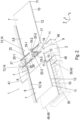
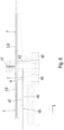
- Figures 1 to 3 in which a laser cutting machine is illustrated for carrying out the method according to the invention for cutting out workpiece parts from a plate-like workpiece.
- the laser cutting machine is designated overall by the reference number 1.
- Figure 1 shows a perspective view of the laser cutting machine 1
- Figure 2 an enlarged part of the laser cutting machine 1, wherein the laser cutting machine 1 is a minor modification compared to that of Figure 1 having,
- Figure 3 a view of the laser cutting machine from Figure 2 .
- the laser cutting machine 1 comprises a base body 2 that is stationary relative to the external environment.
- a flat workpiece support 3 serves to place and transport a plate-shaped workpiece 4 along or against a first axial direction (x-direction) relative to the external environment or to the base body 2.
- a large number of workpiece parts 5 (good parts) are to be cut out of the plate-shaped workpiece 4, whereby a residual grid 6 remains from the plate-shaped workpiece 4 after cutting out at least one workpiece part 5.
- Workpiece parts 5 with different shapes and sizes to be cut out from the plate-shaped workpiece 4 are given by way of example based on their cutting contours.
- the plate-shaped workpiece 4 is, for example, a sheet metal panel from which sheet metal parts with the same or different shapes and sizes are to be cut out.
- the laser cutting machine 1 has three support tables 7 arranged in rows in the x-direction one after the other (separately or separated from each other).
- the two outer support tables 7 are each mounted in a fixed position relative to the external environment or to the base body 2.
- the middle support table 7 is mounted in a fixed position relative to the base body 2 in both the x-direction and the y-direction, but is adjustable in the z-direction (height adjustable). Between There is a gap between the middle support table 7 and one of the two outer support tables 7 (in the figures, for example, the right support table 7) which serves as a cutting gap 9.
- the support tables 7 each comprise a support table endless belt 10 (longitudinal conveyor belt) which is guided around two deflection rollers 11 which are spaced apart from one another in the x-direction and arranged in a fixed manner relative to one another. This achieves a circumferential (rotatable) bearing of the support table endless belt 10.
- the upper belt surface of the support table endless belts 10 each forms a support surface 8 for the plate-shaped workpiece 4, so that each support table 7 has its own support surface 8 which is different from the other support surfaces 8.
- the deflection rollers 11 of the support table endless belts 10 are arranged parallel to the axis in the y-direction.
- One or both deflection rollers 11 of the same support table endless belt 10 are actively driven in order to set the belt in a circumferential movement along or against the x-direction.
- the support rollers 12 serve to support the support surfaces 8 on the bottom.
- the support surfaces 8 of the three support tables 7 are arranged in the same horizontal plane and together form the flat workpiece support 3 for a plate-shaped workpiece 4. If the middle support table 7 is lowered downwards, the support surfaces 8 of the two outer support tables 7 continue to form the flat workpiece support 3 together.
- the cutting gap 9 is formed by the middle support table 7 and the outer support table 7 (i.e. immediately delimited).
- the cutting gap 9 is completely open, i.e. the workpiece support 3 has an opening in the area of the cutting gap 9 which extends continuously (without interruption) along the entire cutting gap length and along the entire cutting gap width.
- each support table 7 has a fixing device 13 for securing a plate-shaped workpiece 4 to the support surface 8.
- the fixing device 13 is designed, for example, as a clamping device which comprises at least one clamping claw 14 by means of which a plate-shaped workpiece 4 can be clamped against the support surface 8.
- the clamping claws 14 are each arranged on the lateral edge of the support surface 8 and are guided so as to be movable in the x-direction.
- the support table endless belts 10 can be moved by actively driving the deflection rollers 11. It would also be conceivable to drive the support table endless belts 10 by actively moving the clamping claws 14 and to let the deflection rollers 11 run only passively.
- a workpiece 4 located on the workpiece support 3 can be moved along or against the x-direction (bidirectional).
- the workpiece 4 can thereby be positioned in the desired manner in relation to the cutting gap 9.
- the workpiece 4 can be positioned in particular such that it spans the cutting gap 9 and simultaneously rests on the support surfaces 8 of the two outer support tables 7.
- the plate-shaped workpiece 4 typically has a correspondingly large dimension in the transport direction of the support table endless belts 10 (x-direction).
- the workpiece support 3 is spanned in a second axial direction (y-direction) by a cross member 16, which is arranged as part of the base body 2 and is fixed to the external environment.
- a (laser) cutting head 17 is attached to the cross member 16 and can be moved along three axial directions by a displacement mechanism 18.
- An embodiment of the displacement mechanism 18 is shown in Figure 1 illustrated. Accordingly, the displacement mechanism 18 comprises, for example, a first guide carriage 19-1, which is guided so as to be movable in the y-direction along first guide rails 20-1, which are attached to the cross member 16 in the direction of its extension.
- Second guide rails 20-2 are attached to the first guide carriage 19-1 in the x-direction (in Figure 1 not visible), along which a second guide carriage 19-2 is movably guided.
- Third guide rails 20-3 are attached to the second guide carriage 19-2 in a third axial direction (z direction), along which a third guide carriage 19-3 carrying the cutting head 17 is movably guided.
- the cutting head 17 can thus be moved in a plane parallel to the horizontal workpiece support 3, the travel mechanism 18 being designed such that the cutting head 17 can only be moved in a specific travel range 21 (which can be freely specified). This means that a laser beam (not shown) guided by the cutting head 17 can only hit the workpiece 4 in a processing zone 24 which lies within the cutting gap 9.
- the cutting head 17 can be moved in height in the z direction, whereby the distance perpendicular to the workpiece support 3 can be changed.
- the cross member 16 comprises two parallel struts 25, to which first guide rails 20-1 are attached to an upper wall section in the direction of extension of the struts 25.
- a first guide carriage 19-1 is guided so as to be movable in the y-direction on the first guide rails 20-1.
- Second guide rails 20-2 are attached to the first guide carriage 19-1 in the x-direction, along which a second guide carriage 19-2 is guided so as to be movable.
- third guide rails 20-3 are attached to the second guide carriage 19-2 in the z-direction, along which a third guide carriage 19-3 carrying the cutting head 17 is guided so as to be movable.
- the cutting head 17 is located in a gap between the two struts 25 of the cross member 16.
- the travel area 21 is designed such that the laser beam guided by the cutting head 17 can only hit the workpiece 4 in a processing zone 24 that lies within the cutting gap 9.
- the cutting head 17 can be adjusted in the z-direction in order to change the distance perpendicular to the workpiece support 3.
- the travel mechanism 18 comprises guide rails 20-1, 20-2, 20-3 arranged in pairs, whereby it is understood that a smaller or larger number of guide rails can be provided.
- a relative movement along or against the x-direction (belt transport direction) between cutting head 17 and workpiece 4 can be achieved by simply moving the Cutting head 17 with the workpiece 4 stationary, by a movement in the x-direction of the cutting head 17 and simultaneous transport of the workpiece 4, or by transporting the workpiece 4 alone with the cutting head 17 stationary at least with respect to the x-direction.
- a relative movement along or against the y-direction and along or against the z-direction between the cutting head 17 and the workpiece 4 always takes place by moving the cutting head 17 with the workpiece 4 stationary.
- the cutting head 17 serves to guide a laser beam that is generated by a laser beam source 26 (not shown in detail) and is guided to the cutting head 17 by light-conducting elements, for example a beam guide tube and deflection mirror.
- a gas laser such as a CO 2 laser, or a solid-state laser, can be used as the laser beam source 26.
- the cutting head 17 contains a focusing device with optical elements for focusing the laser beam onto the plate-shaped workpiece 4.
- the focusing device can comprise, for example, a focusing lens or adaptive optics.
- the laser beam exits the cutting head 17 through a terminal nozzle.
- the cutting head 17 also serves to guide a working gas jet (not shown) which is directed at the processing point of the laser beam and serves to drive the melt produced during laser cutting out of the cutting gap of the workpiece 4.
- the working gas jet is generated by a working gas source 27 (not shown in detail).
- Helium (He), argon (Ar) or nitrogen (N 2 ) is used as an inert working gas, for example.
- Oxygen (O 2 ) is used as a reactive working gas, for example.
- the use of gas mixtures or compressed air is also possible.
- the laser cutting machine 1 further comprises a storage zone 28 with a storage table 29 arranged in the extension of the workpiece support 3 (in the x direction), on which plate-shaped workpieces 4 can be stored in stacks before they are processed.
- a plate-shaped workpiece 4 can be picked up from the storage table 29 and placed on the workpiece support 3.
- the handling device 30 comprises several gripping elements 31, which are designed here, for example, as suction lifters.
- Each gripping element 31 has an end section 32 with a downward-facing contact surface 33 for an object to be picked up.
- the contact surface 33 has at least one suction opening.
- the gripping elements 31 serve in particular to pick up large workpiece parts 5 from the workpiece support 3 and to place them, for example, on pallets 35, which can be stored in particular in a good part storage area 34.
- the pallets 35 are to be suitably positioned for this purpose.
- the handling device 30 comprises a longitudinal beam 36 extending in the x-direction, to which longitudinal beam guide rails 37 are attached in the direction of extension.
- the longitudinal beam 36 extends over the area of the storage zone 28 and at least a partial area of the workpiece support 3.
- At least one gripping member carrier 38 is guided in the longitudinal beam guide rails 37 so as to be movable along and against the x-direction.
- Two gripping member supports 38 are provided, for example.
- the elongated gripping member supports 38 extend in the y-direction and are dimensioned such that they span the workpiece support 3 in the y-direction.
- the gripping member supports 38 are, for example, rigidly connected to one another, so that they can only be moved together.
- the gripping member supports 38 it is possible to design the gripping member supports 38 to be individually movable, in particular an intermediate distance between adjacent gripping member supports 38 being variable.
- At least one elongated gripping member 31 is attached to each of the gripping member supports 38, which is aligned perpendicular to the gripping member support 38 in the z-direction, with the contact surface 33 pointing downwards.
- two gripping elements 31 are provided per gripping element carrier 38.
- the at least one gripping element 31 can be fixedly attached to the associated gripping element carrier 38.
- the gripping member 31 it is also possible for the gripping member 31 to be attached to the gripping member carrier 38 in such a way that it can be moved relative to the gripping member carrier 38 in the y-direction and/or z-direction.
- the position of a gripping member 31 on the gripping member carrier 38 can be changed in the y-direction.
- a height adjustment of the contact surface 33 is possible, in particular to make it easier to pick up and put down an object.
- the handling device 30 comprises, for example, two gripping member carriers 38, each with two gripping members 31, whereby a plate-shaped workpiece 4 can be picked up and held reliably and safely at four spatially spaced locations. It goes without saying that the number of gripping member carriers 38 and gripping members 31 can be adapted to the desired purpose. Likewise, a larger or smaller number of longitudinal carrier guide rails 37 can be provided.
- the plate-shaped workpiece 4 can be brought into a position relative to the cutting gap 9 by transporting it on the workpiece support 3 (rotationally synchronous circulation of the endless belts 10), in which a freely definable section of the plate-shaped workpiece 4 is located in the processing zone 24 of the cutting head 17 above the cutting gap 9.
- This can be an edge section on a workpiece edge 15 of the workpiece 4, wherein the workpiece 4 does not rest on the nearest support table 7 beyond the cutting gap 9, or an inner section of the workpiece 4 located between the two workpiece edges 15, wherein the workpiece 4 spans the cutting gap 9 and at least two support surfaces 8 rest on either side of the cutting gap 9.
- the cutting contour of a workpiece part 5 can, for example, be located completely within the processing zone 24 of the laser beam. The workpiece part 5 can then be cut out without the workpiece 4 having to be transported on the workpiece support 3. If the workpiece part 5 has a dimension in the x-direction that is smaller than the width of the cutting gap 9 (measured in the x-direction), it is a small workpiece part 5 that can be ejected via the cutting gap 9. The same applies to the dimensions of small waste parts that can also be ejected via the cutting gap 9.
- the workpiece 4 must be transported on the workpiece support 3 (rotationally synchronous drive of the endless belts 10) in order to bring a respective section of the cutting contour into the processing zone 24 of the laser beam and to completely cut out the workpiece part 5.
- the workpiece part 5 has a dimension in the x direction that is smaller than the sum of the dimension of the middle support table 7 and the width of the cutting gap 9 (each measured in the x direction), it is a medium-sized workpiece part 5 that can be discharged via the height-adjustable middle support table 7.
- the workpiece part 5 has a dimension in the x-direction that is equal to or greater than the sum of the dimension of the middle support table 7 and the width of the cutting gap 9 (each measured in the x-direction), it is a large workpiece part 5 that is removed from the workpiece support 3 manually or via the handling device 30. It is understood that small and medium-sized workpiece parts 5 each have a dimension in the y-direction that is smaller than the dimension of the cutting gap in the y-direction 9 (cutting gap length).
- the base body 2 of the laser cutting machine 1 comprises a waste part removal device 39 arranged on the bottom, below the cutting gap 9, which comprises an actively driven waste part endless belt 40.
- the waste part endless belt 40 is a longitudinal conveyor belt.
- the waste part endless belt 40 extends in the y-direction at least along the length of the cutting gap 9 and has a width in the x-direction that advantageously corresponds at least to the width of the cutting gap 9.
- the waste part endless belt 40 is located in the fall channel 44 of waste parts falling through the cutting gap 9, so that when a small waste part falls through the cutting gap 9, it reaches the waste part endless belt 40 and can be transported away.
- a waste container 41 can be provided at the end of the waste part endless belt 40, into which waste parts transported over the edge of the waste part endless belt 40 can fall.
- the ability to discharge small waste parts via the cutting gap 9 during cutting can significantly improve the efficiency of parts production.
- the immediate removal of the small waste parts from the residual skeleton 6 improves process reliability with regard to the risk of collision with the cutting head 17.
- the base body 2 of the laser cutting machine 1 has for this purpose at least one deflection element 42 for deflecting small workpiece parts 5 falling through the cutting gap 9, which is designed here, for example, in the form of a pivotable flap.
- the deflection element 42 is pivotably mounted about the pivot axis 43.
- two pivotable deflection elements 42 are provided on both sides of the fall channel 44 for waste parts.
- FIG 4 a situation is shown in which the two deflection elements 42 each assume a vertical position and thus free up the drop channel 44 between the cutting gap 9 and the waste part endless belt 40. Waste parts falling through the cutting gap 9 thus reach the waste part endless belt 40 and can be transported away.
- Each deflection element 42 has a flat deflection surface 45 on one side for small workpiece parts 5 that hit it. If a small workpiece part 5 falling through the cutting gap 9 is to be ejected, one of the two deflection elements 42 is optionally pivoted so that it is located in the drop channel 44 between the cutting gap 9 and the waste part endless belt 40 and crosses the drop channel 44 at least partially, preferably completely.
- the deflection surface 45 is arranged obliquely in the drop channel 44 at an angle other than 0° to the horizontal. Small workpiece parts 5 falling through the cutting gap 9 then hit the deflection surface 45 and are guided out of the fall channel 44.
- Figure 5 considered, wherein the laser cutting machine 1 of Fig.2 with a pivoted deflection element 42 in an enlarged perspective (partial) view.
- the deflection element 42 is inclined, for example, at an angle of approximately 45° to the horizontal, so that small workpiece parts 5 striking the flat deflection surface 45 can be deflected into the good part container 46 arranged below the deflection element 42. It is understood that the deflection element 42 can be arranged at any angle oblique to the horizontal, as long as it is ensured that small workpiece parts 5 striking the deflection surface 45 are deflected into a Area outside the fall channel 44 can be deflected. In Figure 5 a small workpiece part 5 is shown on the deflection surface 45 as an example.
- the good part container 46 placed next to the base body 2 can be easily removed from the laser cutting machine 1 and replaced, for example, with an empty good part container 46.
- the ability to discharge small workpiece parts 5 via the cutting gap 9 can significantly improve the efficiency of parts production. Time-consuming and costly manual or automated removal is not required.
- the cutting process can be continued immediately after a small workpiece part 5 has been cut free.
- the process reliability is improved with regard to the risk of collision with the cutting head 17.
- the waste part endless belt 40 can also have a smaller width than the gap width of the cutting gap 9.
- the middle support table 7 is designed to be height-adjustable, ie adjustable along or against the z-direction. This can be done by a movement mechanism not shown in detail, for example by attaching the middle support table 7 to a guide carriage which is guided in vertically directed guide rails, and moving the guide carriage by an electric linear drive. In this way, the middle support table 7 can be adjusted between a first position, also called the high position (for example in the Figures 2 , 4 and 5 shown), and at least one second position, also called low position (in Figure 6 shown). In the high position, the support surface 8 of the middle Support table 7 together with the support surfaces 8 of the other two support tables 7 form the flat workpiece support 3. In the Figure 6 In the low position shown, a medium-sized workpiece part 5 located on the support surface 8 can be removed from the support surface 8.
- the laser cutting machine 1 comprises a workpiece part removal device 48 arranged below the support tables 7 forming the workpiece support 3, which here comprises, for example, an actively driven workpiece part endless belt 49 with an upper belt support 50 for the transport of medium-sized workpiece parts 5.
- the workpiece part endless belt 49 extends in the x-direction and is designed as a longitudinal conveyor belt.
- the transport direction of the belt support 50 is here, for example, opposite to the x-direction.
- the workpiece part endless belt 49 has a projection in the x-direction relative to the workpiece support 3.
- the middle support table 7 is lowered in the low position so far that its support surface 8 is aligned with the upper belt support 50 of the workpiece part endless belt 49 (i.e. in a common plane).
- the workpiece part 5 can be easily transferred from the support table 7 to the workpiece part endless belt 49 and transported away. Due to the overhang of the workpiece part endless belt 49 relative to the workpiece support 3, workpiece parts 5 on the belt support 50 are easily accessible and can be easily removed manually or, for example, by the handling device 30.
- the workpiece part endless belt 49 can, for example, be movable along or against the x-direction in order to enable a workpiece part 5 to be easily removed from the belt support 50. It would also be possible to place a good part container at the end of the workpiece part endless belt 49 so that workpiece parts 5 transported beyond the end of the workpiece part endless belt 49 can fall into the good part container.
- Figure 7 a situation is shown in which the middle support table 7, on whose support surface 8 a medium-sized workpiece part 5 is shown as an example, is in an intermediate position during the lowering into the Figure 6 shown low position. After the workpiece part 5 has been taken over by the workpiece part endless belt 49, the middle support table 7 can be moved upwards into its high position, where its support surface 8 is (again) part of the flat workpiece support 3.
- no workpiece part removal device 48 is provided.
- the height-adjustable support table 7 can be brought into a low position, for example, in which a workpiece part 5 located on the support surface 8 is transferred to a pallet 35, for example by activating the belt transport of the height-adjustable support table 7.
- the middle support table 7 in a low position can be tilted into an inclined position, so that the workpiece part 5 can slide off the tilted support surface 8, for example onto the workpiece part endless belt 49, a pallet 35 or a good part container.
- the workpiece parts 5 are designed in such a way that they lie statically stable on the support surface 8 of the height-adjustable support table 7. If this is not the case, secure storage can be achieved by securing them to the support surface 8 using a fixing device, for example a suction device with at least one suction opening that can be subjected to negative pressure.
- a fixing device for example a suction device with at least one suction opening that can be subjected to negative pressure.
- the center of gravity of a medium-sized workpiece part 5 intended for discharge by the middle support table 7 is on its support surface 8 when it is cut free, so that it can be discharged immediately.
- large workpiece parts 5 are cut out of the plate-shaped workpiece 4 in the laser cutting machine 1, they can be removed from the workpiece support 3 manually or by the handling device 30.
- the full-surface belt support can significantly reduce the risk of large workpiece parts 5 tipping over relative to the residual grid 6.
- large workpiece parts 5 and the residual grid 6 can be fixed flat on the workpiece support 3 by a fixing device.
- the invention shows a novel method for cutting workpiece parts out of a plate-shaped workpiece using a cutting beam.
- significant advantages can be achieved compared to conventional methods.
- the cutting gap or a single height-adjustable support surface significantly improves process reliability and efficiency in part production, with the laser cutting process continuing during the discharge. Overall, this enables particularly time- and cost-efficient production of workpiece parts.
Landscapes
- Engineering & Computer Science (AREA)
- Physics & Mathematics (AREA)
- Optics & Photonics (AREA)
- Mechanical Engineering (AREA)
- Plasma & Fusion (AREA)
- Laser Beam Processing (AREA)
Claims (15)
- Procédé de découpe de pièces (5) dans une pièce en forme de plaque (4) au moyen d'un jet de découpe guidé dans une fente de découpe (9), qui comprend les étapes suivantes :- placer la pièce en forme de plaque (4) sur un support de pièce (3) composé de trois surfaces de support distinctes (8), dans lequel ces trois surfaces de support (8) sont disposées en rangée et la fente de découpe (9) est délimitée par deux surfaces de support (8) directement voisines des trois surfaces de support (8), dans laquelle la fente de coupe (9) s'étend perpendiculairement à la disposition en rangée des surfaces d'appui (8) et est entièrement ouverte, dans laquelle une seule surface d'appui (8), qui est directement voisine de la fente de coupe (9) et est disposée entre deux autres surfaces d'appui (8), est une surface d'appui réglable en hauteur (8),- découper au moins une pièce (5) de la pièce en forme de plaque (4), avec une grille résiduelle (6),- retirer la pièce découpée (5) de la grille résiduelle (6) en abaissant la surface d'appui réglable en hauteur (8) d'une position haute, dans laquelle la surface d'appui fait partie du support de la pièce, à au moins une position basse,- en retirant la pièce découpée (5) de la surface d'appui réglable en hauteur (8) dans la position basse,- relever la surface d'appui réglable en hauteur (8) de la position basse à la position haute.
- Procédé selon la revendication 1, dans lequel seules les pièces à usiner (5) qui sont retirées de la grille résiduelle (6) au moyen de la surface d'appui réglable en hauteur (8) ont une dimension dans la direction d'une largeur de fente de la fente de coupe (9) qui est égale ou supérieure à la largeur de fente.
- Procédé selon la revendication 1 ou 2, dans lequel la surface d'appui réglable en hauteur est réglée entre la position haute et au moins une position basse en réglant la hauteur d'une table d'appui (7) formant la surface d'appui (8).
- Procédé selon l'une des revendications 1 à 3, dans lequel la pièce (5) est transférée de la surface d'appui réglable en hauteur (8) en position basse à un dispositif d'enlèvement de la pièce (48) pour enlever la pièce (5) et l'évacuer.
- Procédé selon la revendication 4, dans lequel la pièce à usiner (5) est transportée par le dispositif d'enlèvement de la pièce à usiner (48) dans une position dans laquelle la pièce à usiner (5) se trouve en dehors d'un espace situé sous le support de pièce à usiner (3) dans la direction de la gravité.
- Procédé selon l'une des revendications 1 à 5, dans lequel, pendant que la surface d'appui réglable en hauteur (8) se trouve en dessous de la position haute, au moins une autre pièce à usiner (5) est au moins partiellement découpée.
- Procédé selon l'une des revendications 1 à 6, dans lequel au moins une pièce (5) est découpée dans la pièce en forme de plaque (4) de telle sorte qu'elle tombe à travers la fente de coupe (9).
- Procédé selon l'une des revendications 1 à 7, dans lequel au moins une pièce de rebut est découpée dans la pièce en forme de plaque (4) de telle sorte qu'elle tombe à travers la fente de coupe (9).
- Procédé selon les revendications 7 et 8, dans lequel la pièce (5) et/ou le déchet tombant à travers la fente de coupe (9) est dévié de sa direction de chute.
- Procédé selon la revendication 9, dans lequel différentes pièces (5) et/ou différents déchets tombant à travers la fente de coupe (9) sont déviés dans des directions différentes les uns des autres.
- Procédé selon l'une des revendications 8 à 10, dans lequel les déchets tombant à travers la fente de coupe (9) atteignent un dispositif d'enlèvement des déchets (39) pour enlever les déchets et sont enlevés.
- Procédé selon l'une des revendications 1 à 11, dans lequel au moins une pièce (5) est retirée de la grille résiduelle (6) en saisissant la pièce (5) au moyen d'un dispositif de manutention (30).
- Procédé selon la revendication 12, dans lequel seules les pièces (5) qui sont retirées de la grille résiduelle (6) au moyen du dispositif de manutention (30) et qui ont une dimension en direction de la largeur de la fente de coupe (9) qui est égale ou supérieure à la somme de la dimension de l'au moins une surface d'appui réglable en hauteur (8) et de la largeur de la fente de coupe (9).
- Procédé selon l'une des revendications 1 à 13, dans lequel la pièce en forme de plaque (4) est supportée sur toute sa surface par les surfaces d'appui (8) formant le support de pièce (3).
- Procédé selon l'une des revendications 1 à 14, dans lequel au moins une pièce découpée (5) et/ou la grille résiduelle (6) est fixée sur au moins une surface de support (8).
Applications Claiming Priority (2)
| Application Number | Priority Date | Filing Date | Title |
|---|---|---|---|
| EP18164101.0A EP3546114A1 (fr) | 2018-03-26 | 2018-03-26 | Procédé de découpage des parties d'une pièce à usiner |
| PCT/EP2019/057568 WO2019185619A1 (fr) | 2018-03-26 | 2019-03-26 | Procédé servant à découper des parties de pièce |
Publications (2)
| Publication Number | Publication Date |
|---|---|
| EP3774169A1 EP3774169A1 (fr) | 2021-02-17 |
| EP3774169B1 true EP3774169B1 (fr) | 2024-05-08 |
Family
ID=61827535
Family Applications (2)
| Application Number | Title | Priority Date | Filing Date |
|---|---|---|---|
| EP18164101.0A Withdrawn EP3546114A1 (fr) | 2018-03-26 | 2018-03-26 | Procédé de découpage des parties d'une pièce à usiner |
| EP19712779.8A Active EP3774169B1 (fr) | 2018-03-26 | 2019-03-26 | Procédé de découpage des parties d'une pièce |
Family Applications Before (1)
| Application Number | Title | Priority Date | Filing Date |
|---|---|---|---|
| EP18164101.0A Withdrawn EP3546114A1 (fr) | 2018-03-26 | 2018-03-26 | Procédé de découpage des parties d'une pièce à usiner |
Country Status (2)
| Country | Link |
|---|---|
| EP (2) | EP3546114A1 (fr) |
| WO (1) | WO2019185619A1 (fr) |
Families Citing this family (5)
| Publication number | Priority date | Publication date | Assignee | Title |
|---|---|---|---|---|
| IT201900019220A1 (it) * | 2019-10-18 | 2021-04-18 | Maria Incampo | Griglia di aerazione a filo muro |
| CN112935572B (zh) * | 2019-11-26 | 2022-06-28 | 中车唐山机车车辆有限公司 | 一种小三角形工件的下料方法 |
| DE102022123795A1 (de) * | 2022-09-16 | 2024-03-21 | TRUMPF Werkzeugmaschinen SE + Co. KG | Verfahren und System zum Anpassen eines Steuerungsplans zum Steuern eines Laserschneidvorgangs einer Laserschneidanlage |
| PL442946A1 (pl) * | 2022-11-25 | 2024-05-27 | Ejma Janusz Marcin Eagle Power | Wycinarka laserowa i sposób ciągłego cięcia blachy oraz segregacji detali i odpadów w wycinarce laserowej |
| CN117444367A (zh) * | 2023-11-13 | 2024-01-26 | 无锡富泰盛精模科技有限公司 | 一种用于高压油轨轨管的等离子加工设备 |
Citations (1)
| Publication number | Priority date | Publication date | Assignee | Title |
|---|---|---|---|---|
| DE102011054360A1 (de) * | 2011-10-10 | 2013-04-11 | Trumpf Werkzeugmaschinen Gmbh + Co. Kg | Werkzeugmaschine und Verfahren zur Herstellung von Werkstücken |
Family Cites Families (4)
| Publication number | Priority date | Publication date | Assignee | Title |
|---|---|---|---|---|
| ATE507910T1 (de) * | 2007-06-30 | 2011-05-15 | Trumpf Werkzeugmaschinen Gmbh | Werkzeugmaschine und verfahren zum verbringen eines werkstückteils aus einer auflageposition in eine abfuhrposition |
| EP2177293B1 (fr) * | 2008-10-17 | 2013-01-02 | TRUMPF Werkzeugmaschinen GmbH + Co. KG | Procédé d'extraction d'une partie d'une pièce à usiner et machine-outil |
| SI2398621T1 (sl) * | 2009-01-20 | 2019-08-30 | Lasercoil Technologies, Llc | Lasersko rezanje iz transportnega sistema navitega tračnega profila |
| DE102013226818B4 (de) * | 2013-12-20 | 2015-07-30 | Trumpf Werkzeugmaschinen Gmbh + Co. Kg | Maschine zum trennenden Bearbeiten von plattenförmigen Werkstücken |
-
2018
- 2018-03-26 EP EP18164101.0A patent/EP3546114A1/fr not_active Withdrawn
-
2019
- 2019-03-26 EP EP19712779.8A patent/EP3774169B1/fr active Active
- 2019-03-26 WO PCT/EP2019/057568 patent/WO2019185619A1/fr not_active Ceased
Patent Citations (1)
| Publication number | Priority date | Publication date | Assignee | Title |
|---|---|---|---|---|
| DE102011054360A1 (de) * | 2011-10-10 | 2013-04-11 | Trumpf Werkzeugmaschinen Gmbh + Co. Kg | Werkzeugmaschine und Verfahren zur Herstellung von Werkstücken |
Also Published As
| Publication number | Publication date |
|---|---|
| EP3546114A1 (fr) | 2019-10-02 |
| WO2019185619A1 (fr) | 2019-10-03 |
| EP3774169A1 (fr) | 2021-02-17 |
Similar Documents
| Publication | Publication Date | Title |
|---|---|---|
| EP3774169B1 (fr) | Procédé de découpage des parties d'une pièce | |
| DE102013226821B4 (de) | Maschine zum trennenden Bearbeiten von plattenförmigen Werkstücken, Verfahren zum trennenden Bearbeiten eines Werkstücks und Computerprogrammprodukt | |
| DE102013226818B4 (de) | Maschine zum trennenden Bearbeiten von plattenförmigen Werkstücken | |
| EP2492041B1 (fr) | Dispositif avec un dispositif d'usinage de tuyau ; Méthode de déchargement d'un tuyau utilisant un tel dispositif | |
| DE102010027927B4 (de) | Laserbearbeitungsmaschine und Verfahren zum Umrüsten derselben | |
| EP3468730B1 (fr) | Dispositif de chargement et de déchargement pour une machine, machine d'usinage de pièces en forme de plaques, et procédé de chargement et de déchargement d'une telle machine | |
| DE102011054360A1 (de) | Werkzeugmaschine und Verfahren zur Herstellung von Werkstücken | |
| DE102013226816A1 (de) | Maschine zum trennenden Bearbeiten von plattenförmigen Werkstücken | |
| DE102011054361A1 (de) | Verfahren zur Herstellung von Werkstücken aus einem plattenförmigen Material | |
| EP3595827B1 (fr) | Dispositif de centrage | |
| EP1836021B1 (fr) | Procede de decoupe de panneaux, notamment de toles, et dispositif de decoupe destine a la mise en oeuvre de ce procede | |
| EP1425142B1 (fr) | Dispositif pour loger des materiaux plats lors de leur sectionnement au moyen d'un dispositif de coupe, et procede de sectionnement | |
| EP0289834B1 (fr) | Système de fabrication flexible avec machines-outils placées parallèlement à une certaine distance les uns des autres | |
| EP3433049B1 (fr) | Machine de traitement pour couper des pièces en forme de plaque | |
| EP3774163B1 (fr) | Dispositif de découpage de parties de pièce | |
| DE102010014440A1 (de) | Stapelvorrichtung und Verfahren zum Stapeln länglicher Werkstücke | |
| EP3515628B1 (fr) | Procédé et machine-outil servant à l'usinage de pièces en forme de plaque, en particulier de tôles | |
| DE102011051156B4 (de) | Bearbeitungsmaschine sowie deren Bearbeitungsverfahren | |
| DE10220291A1 (de) | Schneidevorrichtung für plattenförmige Werkstücke (Nestbased Manufacturing) | |
| DE19517295A1 (de) | Einrichtung zum Beschicken von Plattenaufteilanlagen mit plattenförmigen Werkstücken | |
| DE10118813A1 (de) | Vorrichtung zum Abstapeln von Faltschachtelschläuchen | |
| DE102016120151A1 (de) | Verfahren und Werkzeugmaschine zum Bearbeiten von plattenförmigen Werkstücken, insbesondere von Blechen | |
| DE4114896A1 (de) | Arbeitsverfahren zum aufbringen von einseitig offenen schutzschuhen auf ein oder beide enden von prismatischen paketen stangen- oder plattenfoermigen gutes | |
| DE10354706C5 (de) | Werkzeugmaschine mit Transportvorrichtung | |
| DE102022119655A1 (de) | Verfahren und Vorrichtung zum automatischen Schneiden eines Werkstücks |
Legal Events
| Date | Code | Title | Description |
|---|---|---|---|
| STAA | Information on the status of an ep patent application or granted ep patent |
Free format text: STATUS: UNKNOWN |
|
| STAA | Information on the status of an ep patent application or granted ep patent |
Free format text: STATUS: THE INTERNATIONAL PUBLICATION HAS BEEN MADE |
|
| PUAI | Public reference made under article 153(3) epc to a published international application that has entered the european phase |
Free format text: ORIGINAL CODE: 0009012 |
|
| STAA | Information on the status of an ep patent application or granted ep patent |
Free format text: STATUS: REQUEST FOR EXAMINATION WAS MADE |
|
| 17P | Request for examination filed |
Effective date: 20201026 |
|
| AK | Designated contracting states |
Kind code of ref document: A1 Designated state(s): AL AT BE BG CH CY CZ DE DK EE ES FI FR GB GR HR HU IE IS IT LI LT LU LV MC MK MT NL NO PL PT RO RS SE SI SK SM TR |
|
| AX | Request for extension of the european patent |
Extension state: BA ME |
|
| DAV | Request for validation of the european patent (deleted) | ||
| DAX | Request for extension of the european patent (deleted) | ||
| GRAP | Despatch of communication of intention to grant a patent |
Free format text: ORIGINAL CODE: EPIDOSNIGR1 |
|
| STAA | Information on the status of an ep patent application or granted ep patent |
Free format text: STATUS: GRANT OF PATENT IS INTENDED |
|
| INTG | Intention to grant announced |
Effective date: 20231026 |
|
| GRAS | Grant fee paid |
Free format text: ORIGINAL CODE: EPIDOSNIGR3 |
|
| GRAA | (expected) grant |
Free format text: ORIGINAL CODE: 0009210 |
|
| STAA | Information on the status of an ep patent application or granted ep patent |
Free format text: STATUS: THE PATENT HAS BEEN GRANTED |
|
| AK | Designated contracting states |
Kind code of ref document: B1 Designated state(s): AL AT BE BG CH CY CZ DE DK EE ES FI FR GB GR HR HU IE IS IT LI LT LU LV MC MK MT NL NO PL PT RO RS SE SI SK SM TR |
|
| REG | Reference to a national code |
Ref country code: GB Ref legal event code: FG4D Free format text: NOT ENGLISH |
|
| REG | Reference to a national code |
Ref country code: CH Ref legal event code: EP |
|
| REG | Reference to a national code |
Ref country code: DE Ref legal event code: R096 Ref document number: 502019011235 Country of ref document: DE |
|
| REG | Reference to a national code |
Ref country code: IE Ref legal event code: FG4D Free format text: LANGUAGE OF EP DOCUMENT: GERMAN |
|
| REG | Reference to a national code |
Ref country code: LT Ref legal event code: MG9D |
|
| REG | Reference to a national code |
Ref country code: NL Ref legal event code: MP Effective date: 20240508 |
|
| PG25 | Lapsed in a contracting state [announced via postgrant information from national office to epo] |
Ref country code: IS Free format text: LAPSE BECAUSE OF FAILURE TO SUBMIT A TRANSLATION OF THE DESCRIPTION OR TO PAY THE FEE WITHIN THE PRESCRIBED TIME-LIMIT Effective date: 20240908 |
|
| PG25 | Lapsed in a contracting state [announced via postgrant information from national office to epo] |
Ref country code: BG Free format text: LAPSE BECAUSE OF FAILURE TO SUBMIT A TRANSLATION OF THE DESCRIPTION OR TO PAY THE FEE WITHIN THE PRESCRIBED TIME-LIMIT Effective date: 20240508 |
|
| PG25 | Lapsed in a contracting state [announced via postgrant information from national office to epo] |
Ref country code: HR Free format text: LAPSE BECAUSE OF FAILURE TO SUBMIT A TRANSLATION OF THE DESCRIPTION OR TO PAY THE FEE WITHIN THE PRESCRIBED TIME-LIMIT Effective date: 20240508 Ref country code: FI Free format text: LAPSE BECAUSE OF FAILURE TO SUBMIT A TRANSLATION OF THE DESCRIPTION OR TO PAY THE FEE WITHIN THE PRESCRIBED TIME-LIMIT Effective date: 20240508 |
|
| PG25 | Lapsed in a contracting state [announced via postgrant information from national office to epo] |
Ref country code: GR Free format text: LAPSE BECAUSE OF FAILURE TO SUBMIT A TRANSLATION OF THE DESCRIPTION OR TO PAY THE FEE WITHIN THE PRESCRIBED TIME-LIMIT Effective date: 20240809 |
|
| PG25 | Lapsed in a contracting state [announced via postgrant information from national office to epo] |
Ref country code: PT Free format text: LAPSE BECAUSE OF FAILURE TO SUBMIT A TRANSLATION OF THE DESCRIPTION OR TO PAY THE FEE WITHIN THE PRESCRIBED TIME-LIMIT Effective date: 20240909 |
|
| PG25 | Lapsed in a contracting state [announced via postgrant information from national office to epo] |
Ref country code: NL Free format text: LAPSE BECAUSE OF FAILURE TO SUBMIT A TRANSLATION OF THE DESCRIPTION OR TO PAY THE FEE WITHIN THE PRESCRIBED TIME-LIMIT Effective date: 20240508 |
|
| PG25 | Lapsed in a contracting state [announced via postgrant information from national office to epo] |
Ref country code: ES Free format text: LAPSE BECAUSE OF FAILURE TO SUBMIT A TRANSLATION OF THE DESCRIPTION OR TO PAY THE FEE WITHIN THE PRESCRIBED TIME-LIMIT Effective date: 20240508 |
|
| PG25 | Lapsed in a contracting state [announced via postgrant information from national office to epo] |
Ref country code: PL Free format text: LAPSE BECAUSE OF FAILURE TO SUBMIT A TRANSLATION OF THE DESCRIPTION OR TO PAY THE FEE WITHIN THE PRESCRIBED TIME-LIMIT Effective date: 20240508 |
|
| PG25 | Lapsed in a contracting state [announced via postgrant information from national office to epo] |
Ref country code: LV Free format text: LAPSE BECAUSE OF FAILURE TO SUBMIT A TRANSLATION OF THE DESCRIPTION OR TO PAY THE FEE WITHIN THE PRESCRIBED TIME-LIMIT Effective date: 20240508 |
|
| PG25 | Lapsed in a contracting state [announced via postgrant information from national office to epo] |
Ref country code: PT Free format text: LAPSE BECAUSE OF FAILURE TO SUBMIT A TRANSLATION OF THE DESCRIPTION OR TO PAY THE FEE WITHIN THE PRESCRIBED TIME-LIMIT Effective date: 20240909 Ref country code: PL Free format text: LAPSE BECAUSE OF FAILURE TO SUBMIT A TRANSLATION OF THE DESCRIPTION OR TO PAY THE FEE WITHIN THE PRESCRIBED TIME-LIMIT Effective date: 20240508 Ref country code: NO Free format text: LAPSE BECAUSE OF FAILURE TO SUBMIT A TRANSLATION OF THE DESCRIPTION OR TO PAY THE FEE WITHIN THE PRESCRIBED TIME-LIMIT Effective date: 20240808 Ref country code: NL Free format text: LAPSE BECAUSE OF FAILURE TO SUBMIT A TRANSLATION OF THE DESCRIPTION OR TO PAY THE FEE WITHIN THE PRESCRIBED TIME-LIMIT Effective date: 20240508 Ref country code: LV Free format text: LAPSE BECAUSE OF FAILURE TO SUBMIT A TRANSLATION OF THE DESCRIPTION OR TO PAY THE FEE WITHIN THE PRESCRIBED TIME-LIMIT Effective date: 20240508 Ref country code: IS Free format text: LAPSE BECAUSE OF FAILURE TO SUBMIT A TRANSLATION OF THE DESCRIPTION OR TO PAY THE FEE WITHIN THE PRESCRIBED TIME-LIMIT Effective date: 20240908 Ref country code: HR Free format text: LAPSE BECAUSE OF FAILURE TO SUBMIT A TRANSLATION OF THE DESCRIPTION OR TO PAY THE FEE WITHIN THE PRESCRIBED TIME-LIMIT Effective date: 20240508 Ref country code: GR Free format text: LAPSE BECAUSE OF FAILURE TO SUBMIT A TRANSLATION OF THE DESCRIPTION OR TO PAY THE FEE WITHIN THE PRESCRIBED TIME-LIMIT Effective date: 20240809 Ref country code: FI Free format text: LAPSE BECAUSE OF FAILURE TO SUBMIT A TRANSLATION OF THE DESCRIPTION OR TO PAY THE FEE WITHIN THE PRESCRIBED TIME-LIMIT Effective date: 20240508 Ref country code: ES Free format text: LAPSE BECAUSE OF FAILURE TO SUBMIT A TRANSLATION OF THE DESCRIPTION OR TO PAY THE FEE WITHIN THE PRESCRIBED TIME-LIMIT Effective date: 20240508 Ref country code: BG Free format text: LAPSE BECAUSE OF FAILURE TO SUBMIT A TRANSLATION OF THE DESCRIPTION OR TO PAY THE FEE WITHIN THE PRESCRIBED TIME-LIMIT Effective date: 20240508 Ref country code: RS Free format text: LAPSE BECAUSE OF FAILURE TO SUBMIT A TRANSLATION OF THE DESCRIPTION OR TO PAY THE FEE WITHIN THE PRESCRIBED TIME-LIMIT Effective date: 20240808 |
|
| PG25 | Lapsed in a contracting state [announced via postgrant information from national office to epo] |
Ref country code: DK Free format text: LAPSE BECAUSE OF FAILURE TO SUBMIT A TRANSLATION OF THE DESCRIPTION OR TO PAY THE FEE WITHIN THE PRESCRIBED TIME-LIMIT Effective date: 20240508 |
|
| PG25 | Lapsed in a contracting state [announced via postgrant information from national office to epo] |
Ref country code: EE Free format text: LAPSE BECAUSE OF FAILURE TO SUBMIT A TRANSLATION OF THE DESCRIPTION OR TO PAY THE FEE WITHIN THE PRESCRIBED TIME-LIMIT Effective date: 20240508 |
|
| PG25 | Lapsed in a contracting state [announced via postgrant information from national office to epo] |
Ref country code: CZ Free format text: LAPSE BECAUSE OF FAILURE TO SUBMIT A TRANSLATION OF THE DESCRIPTION OR TO PAY THE FEE WITHIN THE PRESCRIBED TIME-LIMIT Effective date: 20240508 |
|
| PG25 | Lapsed in a contracting state [announced via postgrant information from national office to epo] |
Ref country code: SK Free format text: LAPSE BECAUSE OF FAILURE TO SUBMIT A TRANSLATION OF THE DESCRIPTION OR TO PAY THE FEE WITHIN THE PRESCRIBED TIME-LIMIT Effective date: 20240508 Ref country code: RO Free format text: LAPSE BECAUSE OF FAILURE TO SUBMIT A TRANSLATION OF THE DESCRIPTION OR TO PAY THE FEE WITHIN THE PRESCRIBED TIME-LIMIT Effective date: 20240508 |
|
| PG25 | Lapsed in a contracting state [announced via postgrant information from national office to epo] |
Ref country code: SM Free format text: LAPSE BECAUSE OF FAILURE TO SUBMIT A TRANSLATION OF THE DESCRIPTION OR TO PAY THE FEE WITHIN THE PRESCRIBED TIME-LIMIT Effective date: 20240508 |
|
| PG25 | Lapsed in a contracting state [announced via postgrant information from national office to epo] |
Ref country code: SM Free format text: LAPSE BECAUSE OF FAILURE TO SUBMIT A TRANSLATION OF THE DESCRIPTION OR TO PAY THE FEE WITHIN THE PRESCRIBED TIME-LIMIT Effective date: 20240508 Ref country code: SK Free format text: LAPSE BECAUSE OF FAILURE TO SUBMIT A TRANSLATION OF THE DESCRIPTION OR TO PAY THE FEE WITHIN THE PRESCRIBED TIME-LIMIT Effective date: 20240508 Ref country code: RO Free format text: LAPSE BECAUSE OF FAILURE TO SUBMIT A TRANSLATION OF THE DESCRIPTION OR TO PAY THE FEE WITHIN THE PRESCRIBED TIME-LIMIT Effective date: 20240508 Ref country code: EE Free format text: LAPSE BECAUSE OF FAILURE TO SUBMIT A TRANSLATION OF THE DESCRIPTION OR TO PAY THE FEE WITHIN THE PRESCRIBED TIME-LIMIT Effective date: 20240508 Ref country code: DK Free format text: LAPSE BECAUSE OF FAILURE TO SUBMIT A TRANSLATION OF THE DESCRIPTION OR TO PAY THE FEE WITHIN THE PRESCRIBED TIME-LIMIT Effective date: 20240508 Ref country code: CZ Free format text: LAPSE BECAUSE OF FAILURE TO SUBMIT A TRANSLATION OF THE DESCRIPTION OR TO PAY THE FEE WITHIN THE PRESCRIBED TIME-LIMIT Effective date: 20240508 |
|
| PG25 | Lapsed in a contracting state [announced via postgrant information from national office to epo] |
Ref country code: IT Free format text: LAPSE BECAUSE OF FAILURE TO SUBMIT A TRANSLATION OF THE DESCRIPTION OR TO PAY THE FEE WITHIN THE PRESCRIBED TIME-LIMIT Effective date: 20240508 |
|
| REG | Reference to a national code |
Ref country code: DE Ref legal event code: R097 Ref document number: 502019011235 Country of ref document: DE |
|
| PLBE | No opposition filed within time limit |
Free format text: ORIGINAL CODE: 0009261 |
|
| STAA | Information on the status of an ep patent application or granted ep patent |
Free format text: STATUS: NO OPPOSITION FILED WITHIN TIME LIMIT |
|
| 26N | No opposition filed |
Effective date: 20250211 |
|
| PG25 | Lapsed in a contracting state [announced via postgrant information from national office to epo] |
Ref country code: SI Free format text: LAPSE BECAUSE OF FAILURE TO SUBMIT A TRANSLATION OF THE DESCRIPTION OR TO PAY THE FEE WITHIN THE PRESCRIBED TIME-LIMIT Effective date: 20240508 |
|
| PG25 | Lapsed in a contracting state [announced via postgrant information from national office to epo] |
Ref country code: SE Free format text: LAPSE BECAUSE OF FAILURE TO SUBMIT A TRANSLATION OF THE DESCRIPTION OR TO PAY THE FEE WITHIN THE PRESCRIBED TIME-LIMIT Effective date: 20240508 |
|
| PG25 | Lapsed in a contracting state [announced via postgrant information from national office to epo] |
Ref country code: MC Free format text: LAPSE BECAUSE OF FAILURE TO SUBMIT A TRANSLATION OF THE DESCRIPTION OR TO PAY THE FEE WITHIN THE PRESCRIBED TIME-LIMIT Effective date: 20240508 |
|
| REG | Reference to a national code |
Ref country code: CH Ref legal event code: H13 Free format text: ST27 STATUS EVENT CODE: U-0-0-H10-H13 (AS PROVIDED BY THE NATIONAL OFFICE) Effective date: 20251023 |
|
| PG25 | Lapsed in a contracting state [announced via postgrant information from national office to epo] |
Ref country code: LU Free format text: LAPSE BECAUSE OF NON-PAYMENT OF DUE FEES Effective date: 20250326 |
|
| GBPC | Gb: european patent ceased through non-payment of renewal fee |
Effective date: 20250326 |
|
| REG | Reference to a national code |
Ref country code: BE Ref legal event code: MM Effective date: 20250331 |
|
| PG25 | Lapsed in a contracting state [announced via postgrant information from national office to epo] |
Ref country code: GB Free format text: LAPSE BECAUSE OF NON-PAYMENT OF DUE FEES Effective date: 20250326 |
|
| PG25 | Lapsed in a contracting state [announced via postgrant information from national office to epo] |
Ref country code: FR Free format text: LAPSE BECAUSE OF NON-PAYMENT OF DUE FEES Effective date: 20250331 |
|
| PG25 | Lapsed in a contracting state [announced via postgrant information from national office to epo] |
Ref country code: BE Free format text: LAPSE BECAUSE OF NON-PAYMENT OF DUE FEES Effective date: 20250331 |
|
| PG25 | Lapsed in a contracting state [announced via postgrant information from national office to epo] |
Ref country code: CH Free format text: LAPSE BECAUSE OF NON-PAYMENT OF DUE FEES Effective date: 20250331 |
|
| PG25 | Lapsed in a contracting state [announced via postgrant information from national office to epo] |
Ref country code: IE Free format text: LAPSE BECAUSE OF NON-PAYMENT OF DUE FEES Effective date: 20250326 |
|
| PGFP | Annual fee paid to national office [announced via postgrant information from national office to epo] |
Ref country code: DE Payment date: 20260320 Year of fee payment: 8 |