EP3774600B1 - Support de transporteur - Google Patents
Support de transporteur Download PDFInfo
- Publication number
- EP3774600B1 EP3774600B1 EP19786106.5A EP19786106A EP3774600B1 EP 3774600 B1 EP3774600 B1 EP 3774600B1 EP 19786106 A EP19786106 A EP 19786106A EP 3774600 B1 EP3774600 B1 EP 3774600B1
- Authority
- EP
- European Patent Office
- Prior art keywords
- wearstrip
- extending
- notch
- bracket
- brackets
- Prior art date
- Legal status (The legal status is an assumption and is not a legal conclusion. Google has not performed a legal analysis and makes no representation as to the accuracy of the status listed.)
- Active
Links
Images




Classifications
-
- B—PERFORMING OPERATIONS; TRANSPORTING
- B65—CONVEYING; PACKING; STORING; HANDLING THIN OR FILAMENTARY MATERIAL
- B65G—TRANSPORT OR STORAGE DEVICES, e.g. CONVEYORS FOR LOADING OR TIPPING, SHOP CONVEYOR SYSTEMS OR PNEUMATIC TUBE CONVEYORS
- B65G15/00—Conveyors having endless load-conveying surfaces, i.e. belts and like continuous members, to which tractive effort is transmitted by means other than endless driving elements of similar configuration
- B65G15/08—Conveyors having endless load-conveying surfaces, i.e. belts and like continuous members, to which tractive effort is transmitted by means other than endless driving elements of similar configuration the load-carrying surface being formed by a concave or tubular belt, e.g. a belt forming a trough
-
- B—PERFORMING OPERATIONS; TRANSPORTING
- B65—CONVEYING; PACKING; STORING; HANDLING THIN OR FILAMENTARY MATERIAL
- B65G—TRANSPORT OR STORAGE DEVICES, e.g. CONVEYORS FOR LOADING OR TIPPING, SHOP CONVEYOR SYSTEMS OR PNEUMATIC TUBE CONVEYORS
- B65G15/00—Conveyors having endless load-conveying surfaces, i.e. belts and like continuous members, to which tractive effort is transmitted by means other than endless driving elements of similar configuration
- B65G15/60—Arrangements for supporting or guiding belts, e.g. by fluid jets
-
- B—PERFORMING OPERATIONS; TRANSPORTING
- B65—CONVEYING; PACKING; STORING; HANDLING THIN OR FILAMENTARY MATERIAL
- B65G—TRANSPORT OR STORAGE DEVICES, e.g. CONVEYORS FOR LOADING OR TIPPING, SHOP CONVEYOR SYSTEMS OR PNEUMATIC TUBE CONVEYORS
- B65G15/00—Conveyors having endless load-conveying surfaces, i.e. belts and like continuous members, to which tractive effort is transmitted by means other than endless driving elements of similar configuration
- B65G15/60—Arrangements for supporting or guiding belts, e.g. by fluid jets
- B65G15/62—Guides for sliding belts
-
- B—PERFORMING OPERATIONS; TRANSPORTING
- B65—CONVEYING; PACKING; STORING; HANDLING THIN OR FILAMENTARY MATERIAL
- B65G—TRANSPORT OR STORAGE DEVICES, e.g. CONVEYORS FOR LOADING OR TIPPING, SHOP CONVEYOR SYSTEMS OR PNEUMATIC TUBE CONVEYORS
- B65G21/00—Supporting or protective framework or housings for endless load-carriers or traction elements of belt or chain conveyors
- B65G21/20—Means incorporated in, or attached to, framework or housings for guiding load-carriers, traction elements or loads supported on moving surfaces
-
- B—PERFORMING OPERATIONS; TRANSPORTING
- B65—CONVEYING; PACKING; STORING; HANDLING THIN OR FILAMENTARY MATERIAL
- B65G—TRANSPORT OR STORAGE DEVICES, e.g. CONVEYORS FOR LOADING OR TIPPING, SHOP CONVEYOR SYSTEMS OR PNEUMATIC TUBE CONVEYORS
- B65G21/00—Supporting or protective framework or housings for endless load-carriers or traction elements of belt or chain conveyors
- B65G21/20—Means incorporated in, or attached to, framework or housings for guiding load-carriers, traction elements or loads supported on moving surfaces
- B65G21/22—Rails or the like engaging sliding elements or rollers attached to load-carriers or traction elements
-
- B—PERFORMING OPERATIONS; TRANSPORTING
- B65—CONVEYING; PACKING; STORING; HANDLING THIN OR FILAMENTARY MATERIAL
- B65G—TRANSPORT OR STORAGE DEVICES, e.g. CONVEYORS FOR LOADING OR TIPPING, SHOP CONVEYOR SYSTEMS OR PNEUMATIC TUBE CONVEYORS
- B65G2207/00—Indexing codes relating to constructional details, configuration and additional features of a handling device, e.g. Conveyors
- B65G2207/30—Modular constructions
-
- B—PERFORMING OPERATIONS; TRANSPORTING
- B65—CONVEYING; PACKING; STORING; HANDLING THIN OR FILAMENTARY MATERIAL
- B65G—TRANSPORT OR STORAGE DEVICES, e.g. CONVEYORS FOR LOADING OR TIPPING, SHOP CONVEYOR SYSTEMS OR PNEUMATIC TUBE CONVEYORS
- B65G2207/00—Indexing codes relating to constructional details, configuration and additional features of a handling device, e.g. Conveyors
- B65G2207/48—Wear protection or indication features
Definitions
- the invention relates generally to frames for power-driven conveyors. More particularly, the invention relates to brackets used to convert a pre-existing conveyor frame to a conveyor frame usable with a new or different type of conveyor belt, a conveyor converted from a first type of conveyor belt to a second type of conveyor belt and a method for performing the conversion.
- Roller conveyors for example, consist of an array of metal rollers arranged side by side along the length of a conveyor frame. The ends of the rollers are retained in opposite sides of the conveyor frame. The rollers rotate about axes directed widthwise across the conveyor perpendicular to the conveyance direction. The rollers may be passive, but are commonly driven to rotate by a drive belt. The width of the conveyor frame is fixed to accommodate the axial length of the rollers. Roller conveyors work well, but are notoriously noisy and often require repair.
- flat belt conveyors are also commonly used to transport articles. These conveyors include flat rubber or fabric belts tensioned between drive and idler pulleys at opposite ends. But a flat belt can drift to one side of the pulleys and stretch over time. If it tears, the belt must be removed from the conveyor, the torn section cut out, and a new section spliced in.
- thermoplastic low tension direct drive conveyor belts examples of which include, but are not limited to Thermodrive ® , available from Intralox, LLC of Harahan, LA,. SuperDrive TM , available from Volta Belting and others known in the art.
- Thermodrive ® available from Intralox, LLC of Harahan, LA,.
- SuperDrive TM available from Volta Belting and others known in the art.
- converting to a modular belt conveyor from a roller conveyor, a flat belt conveyor, or another type of conveyor is usually a time-consuming and costly operation and requires the addition of wearstrips or other components. The conversion is difficult mainly because conveyor frames are typically designed to accommodate the rollers or the belt they were originally specified to be used with.
- WO 2017/087321 A1 discloses a conversion bracket for converting a conveyor frame to accommodate a conveyor belt.
- the bracket includes a base, a plurality of shaft holders extending from a first end of the base and a plurality of wearstrip receptacles extending from a second end of the base.
- the bracket attaches to a shaft of a conveyor frame by inserting the shaft into the shaft holders. Wearstrips are inserted into the wearstrip receptacles, which are oriented and configured so that the inserted wearstrips rest on the tops of the shaft.
- WO 2017/087321 A1 discloses a conversion kit for converting a conveyor frame to accommodate wearstrips forming a carryway for a conveyor belt according to the preamble of claim 1, a conversion kit for converting a conveyor frame comprising a plurality of shaft to accommodate wearstrips forming a carryway for a conveyor belt according to the preamble of claim 5 as well as a method of retrofitting a positive-drive low tension thermoplastic conveyor belt to a flat belt conveyor frame according to the preamble of claim 12.
- a retrofit kit for converting a conveyor frame to enable a conveyor belt comprises brackets for mounting wearstrips forming a carryway for a conveyor belt.
- Each bracket includes a shaft holder for seating a shaft of the conveyor frame and a wearstrip seat for seating a wearstrip forming a carryway for the conveyor belt.
- a wearstrip configured to interlock with the brackets includes a nonlinear channel for coupling to a wearstrip seat.
- a conversion kit for converting a conveyor frame to accommodate wearstrips forming a carryway for a conveyor belt comprises a first bracket and a wearstrip.
- the first bracket comprises a base, a wearstrip seat formed in the base for receiving a wearstrip and a shaft holder comprising a protrusion extending from the base and a shaft seat at the end of the protrusion for seating a shaft of the conveyor frame.
- the wearstrip has a nonlinear channel for interlocking with the wearstrip seat.
- a bracket for connecting a wearstrip to a conveyor frame shaft comprises a base extending laterally from a first side to a second side, a shaft holder comprising a protrusion extending from the base and having an opening for receiving the conveyor frame shaft and a wearstrip seat comprising a shallow notch in an upper edge of the base separated from an elongated opening by a lateral beam.
- a method of retrofitting a positive-drive low tension thermoplastic conveyor belt to a flat belt conveyor frame comprises the steps of attaching a plurality of conversion brackets to shafts on the conveyor frame, each conversion bracket including a plurality of shaft seats and a plurality of wearstrip seats and inserting a wearstrip having a nonlinear channel into a wearstrip seat, such that the wearstrip is held above the shafts.
- a bracket for connecting a wearstrip and containment block to a longitudinally extending spine of a conveyor frame comprises a base extending laterally from a first side to a second side, a wearstrip seat formed in an upper edge of the base for receiving a wearstrip, an opening in a bottom edge of the base for mounting the base on a shaft and a containment block receptacle formed in the first side of the base for interlocking with a containment block.
- the containment block receptacle comprises a planar sheet extending perpendicular to the base, a first elongated opening in the planar sheet below a top edge of the planar sheet and a second elongated opening aligned with the first elongated opening formed in the base near the first side.
- a conversion kit for converting a conveyor frame to accommodate wearstrips forming a carryway for a conveyor belt comprises a plurality of straight brackets and a plurality of curved brackets.
- Each straight bracket extends from a first side to a second side and has a plurality of first open slots in an upper edge.
- a first flange extends up from the first side and has a second open slot extending perpendicular to the first open slots.
- a second flange extends up from the second side and has a third open slot extending parallel to the second open slot.
- Each curved bracket has a curved base extending from a first side to a second side and a plurality of fourth open slots in an upper edge of the curved base.
- a third flange extends perpendicular to the upper edge at the first side and has a fifth open slot facing inwards and extending perpendicular to the third flange.
- a fourth flange extends perpendicular to the upper edge at the second edge and has a sixth open slot facing inwards extending perpendicular to the fourth flange.
- the straight brackets are mounted at first and second ends of a spine and the curved brackets are mounted at intermediate points on the spine.
- a kit for converting a conveyor frame includes a plurality of brackets that include wearstrip seats for seating wearstrips designed to interlock with the brackets to form a carryway for a conveyor belt.
- the invention will be described relative to certain illustrative embodiments.
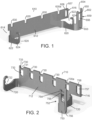
- FIGS. 1 and 2 show two conveyor brackets 610, 710 suitable for cooperating to connect wearstrips to shafts in a conveyor frame.
- the first conveyor bracket 610 includes a base 612 comprising a substantially planar metal substrate extending laterally from a first side 614 to a second side 616.
- a plurality of shaft holders 620 extend from a first (front) end of the bracket for attaching the bracket 610 to a shaft in a pre-existing conveyor frame, as described below.
- Each illustrative shaft holder 620 comprises a protrusion extending from the base that curls up and inwards to form a seat 622 for receiving the shaft.
- the opening 622 is sized and positioned based on the size of the shaft.
- the shaft opening of the bracket may have any suitable size, shape and configuration to accommodate a particular size and shape conveyor component, such as a shaft.
- Each shaft opening 622 also includes cleaning recesses 624 to promote hygiene, though the invention is not so limited.
- the conveyor brackets 610, 710 are laser-cut from stainless steel that is bent-to-order, though the invention is not so limited.
- the base 612 may have any suitable number of shaft holders 620 spaced apart at any suitable intervals.
- the shaft holder 620 can be sized and shaped to accommodate any suitable conveyor frame shaft.
- the bracket 610 also includes a plurality of wearstrip receptacles 630 formed in the top edge of the base for connecting wearstrips forming a carryway for a conveyor belt to shafts held in the shaft openings 622.
- Each wearstrip receptacle 630 comprises a notch in the upper edge of the base sized and configured to receive a wearstrip.
- Each illustrative notch slightly flares out at the bottom, but the invention is not so limited.
- the second conveyor bracket 710 includes wearstrip receptacles 730 that comprise a shallow notch 731 in an upper edge of a base 712 separated from an elongated opening 732 by a lateral beam 733.
- the elongated opening 732 has a rounded bottom.
- the conveyor bracket 710 also includes shaft holders 720 having curved seats 722 for mounting the bracket 710 to a shaft of a conveyor frame.
- the brackets 610 and 710 may also include containment block receptacles 652, 752 at the second side 616, 716 of the bases 612, 712 for mounting side guards that flank the carryway to contain the conveyor belt.
- the brackets 610, 710 may include containment block receptacles on one or both sides.
- the illustrative containment block receptacles 652 comprises a planar sheet 653 extending from and substantially perpendicular to a shaft holder 620 on the second side 616.
- the planar sheet 653 has an upper shallow notch 654, a lateral beam 655 and an elongated opening 656 with a rounded bottom.
- the second side 616 of the base 612 has an elongated, rounded bottom opening 657 aligned with and mirroring the elongated opening 656 in the planar sheet 653.
- a lateral beam 658 forming a portion of the top edge of the base 612 caps the elongated opening and aligns with beam 655.
- the outer edge 659 of planar sheet 653 aligns with the edge 616 of base 612.
- the containment block receptacle 752 of bracket 710 mirror the containment block receptacle of bracket 610, including planar sheet 753, notch 754, aligned lateral beams 755, 758 and aligned elongated openings 756, 757.
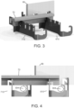
- the brackets 610, 710 can cooperate to mount wearstrips for a conveyor belt as shown in FIGS. 3 and 4 .
- the brackets 610, 710 are mounted on shafts 304 by inserting the shafts 304 into the shaft seats 622, 722, thereby connecting the wearstrip receptacles 630, 730 to the shafts 304.
- the shaft holders 620, 720 can be welded to the shafts or otherwise affixed thereto.
- wearstrips 70 are inserted in the associated wearstrip receptacles 630, 730.
- a wearstrip 70 can extend between a first wearstrip receptacle 630a on the first bracket 610 to a second wearstrip receptacle 730a aligned with the first wearstrip receptacle 630a to connected the brackets 610, 710 together.
- a containment block 80 defining a side guard at the edges of a carryway is inserted in the containment block receptacle 652.
- the components of the brackets 610, 710 are oriented such that the wearstrip 70 extends substantially perpendicularly to the longitudinal axis of the shafts 304, and the containment block 80 extends substantially parallel to the wearstrip, though the invention is not so limited.
- the wearstrip 70 and containment blocks 80 are designed to interlock with the brackets 610, 710 without requiring additional tools.
- the wearstrip 70 which has a T-shaped cross-section, has a non-linear channel 71 extending up from the bottom surface 72 for mating with a wearstrip receptacle 730 on bracket 710.
- the non-linear channel 71 includes a first vertical portion 73 in communication with and extending up from the bottom surface 72.
- a transverse portion 74 extends downward at an angle from the top of the first vertical portion.
- a second vertical portion 75 extends up from the bottom of the transverse portion 74, which is above the bottom surface 72 of the wearstrip.
- the inlet of the channel 71 is brought near a notch 731 of an associated wearstrip receptacle 730.
- the lateral bar 732 is inserted through the channel 71, finally resting in second vertical portion 75, with the solid portion of the wearstrip below the channel in the elongated opening 732.
- the wearstrip 70 further includes a wider, shallower, linear notch 76 spaced from the channel 71 for coupling with a wearstrip receptacle 630 of a bracket 610.
- the notch 76 can be placed at any suitable location, depending on the spacing of shafts in the conveyor frame undergoing conversion.
- the containment block 80 includes non-linear channels 81, 86 for interlocking the containment block 80 with the containment block receptacles 652 or 752, as shown in FIG. 7 .
- the channels 81, 86 are spaced apart by the same separation distance that separates the planar sheet 653 from the base portion 612 of the bracket 610.
- the width of the brackets 610, 710 can change with conveyor width.
- the spacing of the wearstrips can also change with conveyor width. It is also feasible to manipulate the spacing of the wearstrip to facilitate a conveyor shape or a product loading.
- the invention can also be used to convert a conveyor frame for modular plastic conveyor belts or other conveyor belts and is not limited to a thermoplastic, direct drive conveyor belt.
- the conversion brackets 610, 710 may be used to convert a pre-existing frame, such as a frame 300 shown in FIG. 8 to accommodate a new conveyor belt.
- the frame 300 of FIG. 8 which is known as a "rabbit ear conveyor frame” includes a central spine 302 and a plurality of shafts 304 extending up and out at an angle from the central spine.
- the shafts 304 form "rabbit ears” to allow troughing of a conveyor belt.
- the illustrative shafts 304 are spaced about 2 feet apart along the length of the spine 302.
- a plurality of conversion brackets 610, 710 may be attached to selective shafts 304 in an alternating pattern to allow installation of wearstrips on the frame.
- the conversion brackets 610, 710 are attached by inserting the shafts 304 into the shaft seats 622 or 722 of the brackets 610 or 710.
- wearstrips 70 are inserted into the wearstrip receptacles 630, 730, as shown in FIG. 9 and locked in place using the geometry of the parts.
- the wearstrips 70 can be bent and-or twisted to conform to the wearstrip receptacles, particularly in the transition areas at the ends of the frame.
- the wearstrips 70 when inserted in the wearstrip receptacles 630, 730, rest on the shafts 304 or slightly above the shafts 304 so they can deflect into contact with the shafts 304 under load, allowing the original frame to support the carryway and eliminating the need to remove components of the original frame.
- containment blocks 80 for containing a conveyor belt on the carryway are inserted in the containment block receptacles 652, 752 of the brackets.
- the containment blocks can be alternatively be retained mechanically, such as with a rivet, pin or other fastener. In this manner, the containment blocks 80 can be easily installed, removed and -or replaced as needed.
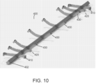
- FIG. 10 shows another embodiment of a converted conveyor frame 400 using a kit comprising a plurality of conversion brackets 410, 420, 430 attached directly to a central spine 402 and including wearstrip receptacles and container block receptacles configured to receive and interlock with wearstrip and containment blocks without requiring additional tools.
- the illustrative converted conveyor frame 400 employs brackets having troughed profiles and straight profiles, but the invention is not so limited.
- the frame 400 includes straight brackets 410 at each end for supporting the belt in the transition areas. The brackets progressively curve towards the center of the belt to create a trough for conveying product.
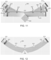
- FIG. 11 is a front view of the converted conveyor frame 400, showing a straight bracket 410, a slightly curved bracket 420 and a troughed bracket 430, each mounted on the spine 402 and including wearstrip receptacles 412 and container block receptacles 414.
- FIG. 12 which is a front view of the troughed bracket 430 shows the bottom opening 416 for mounting the bracket 430 to the central spine 402.
- the wearstrip receptacles and container block receptacles may be similar to those described above with respect to brackets 610, 710 and configured to fit with nonlinear channels on associated wearstrips and containment blocks to assemble the carryway of the conveyor.
- the wearstrip receptacles and container block receptacles may be configured to hold the wearstrips and -or container blocks forming side guards via friction fit, a snap fit, a mechanical fit or any suitable means.
- the brackets 410, 420 and 430 can be welded or otherwise connected to the central spine.
- FIGS. 13 and 14 show another embodiment of a conveyor frame 500 formed using a kit comprising a plurality of brackets 510, 520, 530 for holding wearstrips that form a carryway.
- the brackets are connected to a central spine 502. Brackets 510 at each end of the spine are straight, intermediate brackets 520 have a slight curve and central brackets 530 have a larger curve to form a trough.
- FIG. 15 is a front view of the central bracket 530.
- FIG. 16 shows a portion of a wearstrip 560 suitable for use with the brackets 510, 520, 530 to form a carryway for a conveyor belt.
- the illustrative wearstrip 560 has a T-shaped cross-section.
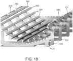
- FIG. 17 shows an embodiment of a support bar 570, which may be to provide extra rigidity to the conveyor frame.
- Each bracket includes a plurality of open slots 550 in a top edge of a base 531 extending from a first side to a second side for receiving and holding a portion of a wearstrip.
- the slots 550 and wearstrips 560 are sized and configured so that the slots 550 hold the wearstrips 560 tightly by pinch design, without requiring tools or connectors.
- each bracket includes a flange 580 extending at a right angle from the top of the bracket base at that side.
- Each flange 580 includes an open slot 581 essentially extending at a right angle to the next nearest open slot 550 ⁇ and facing inwards, towards the lateral middle of the frame.
- a wearstrip inserted in the flange open slot 580 functions as a side guard for a conveyor belt that is mounted on the conveyor frame.
- the side guards extend along each side of a conveyor belt extending along a carryway formed by the top edge open slots 550 to contain the conveyor belt.
- One or more of the flanges 570 may include a recess 590 on an outer surface forming a seat for a reinforcing bar 570.
- reinforcing bars 570 may be seated in the recesses 590 of several central brackets 530 and connected to the brackets to reinforce the frame structure.
- the T-shaped wearstrips may be inserted in the slots, with the stem of each wearstrip received in a slot, and the top portion forming the carryway for contacting and guiding a conveyor belt.
- the outside wearstrips 582 flank the sides of the conveyor belt and the other wearstrips 560 are under the conveyor belt.
- Each curved bracket may further include bracing arms 532 for additional support.
- each bracket includes a bottom opening 516 for mounting the bracket to the central spine 502.
- the conversion kit of the illustrative embodiments allows quick, simplified and economical retrofitting of a conveyor frame to accommodate a new or different conveyor belt.
- the conversion kit limits downtime and while ensuring cleanability of the converted conveyor frame.
- the wearstrips may be easily removed and changed if needed and the lack of connectors, clips, screws or other potential bacteria harborage points enhances hygiene.
Landscapes
- Engineering & Computer Science (AREA)
- Mechanical Engineering (AREA)
- Belt Conveyors (AREA)
Claims (12)
- Kit de conversion pour convertir un châssis de convoyeur (500) pour recevoir des bandes d'usure formant une voie de transport pour une bande transporteuse, comprenant :une pluralité de supports droits (510), chaque support droit (510) s'étendant d'un premier côté à un second côté et une pluralité de supports incurvés, chaque support incurvé ayant une base incurvée s'étendant d'un premier côté à un second côté, dans lequel les supports droits sont montés au niveau de première et deuxième extrémités d'une colonne dorsale et les supports incurvés sont montés au niveau de points intermédiaires sur la colonne dorsale, ledit kit de étant caractérisé en ce que chaque support droit (510) a une pluralité de premières fentes ouvertes (550) dans un bord supérieur, une première bride (580) s'étendant vers le haut à partir du premier côté et ayant une deuxième fente ouverte (581) s'étendant perpendiculairement aux premières fentes ouvertes (550) et une deuxième bride (580) s'étendant vers le haut à partir du deuxième côté et ayant une troisième fente ouverte (581) s'étendant parallèlement à la deuxième fente ouverte (581) ; etchaque support incurvé (520, 530) a une pluralité de quatrièmes fentes ouvertes (550) dans un bord supérieur de la base incurvée (531), une troisième bride (580) s'étendant perpendiculairement au bord supérieur au niveau du premier côté et ayant une cinquième fente ouverte (581) tournée vers l'intérieur et s'étendant perpendiculairement à la troisième bride (580) et une quatrième bride (580) s'étendant perpendiculairement au bord supérieur au niveau du deuxième bord et ayant une sixième fente ouverte (581) tournée vers l'intérieur et s'étendant perpendiculairement à la quatrième bride (580),dans lequel les premières, deuxièmes, troisièmes, quatrièmes, cinquièmes et sixièmes fentes ouvertes (550, 581) sont configurées pour recevoir des bandes d'usure (560).
- Kit de conversion selon la revendication 1, comprenant en outre une pluralité de bandes d'usure (560) configurées pour être insérées dans les premières, deuxièmes, troisièmes, quatrièmes, cinquièmes et sixièmes fentes (550, 581) ouvertes pour former une voie de transport s'étendant depuis la première extrémité de la colonne dorsale jusqu'à la seconde extrémité (502) de la colonne dorsale et pour former des protections latérales pour la voie de transport.
- Kit de conversion selon la revendication 1, dans lequel les troisième et quatrième brides (580) comprennent des évidements (590) sur une surface extérieure pour asseoir une barre de renfort (570).
- Kit de conversion selon la revendication 3, comprenant en outre des barres de renfort (570) placées dans les évidements (590) et s'étendant entre des supports incurvés consécutifs (530).
- Kit de conversion pour convertir un châssis de convoyeur (300) comprenant une pluralité d'arbres pour recevoir des bandes d'usure formant une voie de transport pour une bande transporteuse, comprenant :un premier support (610, 710) comprenant une base (612, 712), un siège de bande d'usure (630, 730) pour recevoir une bande d'usure (70) et un support d'arbre (620, 720) comprenant une saillie s'étendant à partir de la base (612, 712) et un siège d'arbre (622, 722) à l'extrémité de la saillie pour asseoir un arbre (304) du châssis de convoyeur ; caractérisé en ce que le siège de bande d'usure (630, 730) est formé dans la base (612, 712) et ledit kit de conversion comprend en outreune bande (70) d'usure ayant un canal non linéaire (71) pour un verrouillage avec le siège de bande d'usure (630, 730).
- Kit de conversion selon la revendication 5, comprenant en outre un second support (610, 710) ayant un siège d'arbre (622, 722) pour un arbre (304) et un siège de bande d'usure (630, 730) pour recevoir la bande d'usure(70), la bande d'usure (70) ayant une encoche (76) pour venir en prise avec le siège de bande d'usure (630, 730) du second support (610, 710).
- Kit de conversion selon la revendication 5, comprenant en outre un réceptacle de bloc de confinement (652, 752) s'étendant à partir d'un premier côté de la base (612,712).
- Kit de conversion selon la revendication 5, dans lequel a) le réceptacle de bloc de confinement (652, 752) comprend une feuille plane (653, 753) s'étendant perpendiculairement à la saillie du support d'arbre (620, 720), une encoche (654,754) au-dessus de la feuille plane (653,753), une ouverture allongée (656, 756) sous l'encoche (654, 754) et une poutre latérale (655, 755) séparant l'encoche (654, 754) de l'ouverture allongée (656, 756) ; oub) le réceptacle de bloc de confinement (652,752) comprend une feuille plane (653, 753) s'étendant perpendiculairement à la saillie du support d'arbre (620, 720), une encoche (654, 754) au-dessus de la feuille plane (653, 753), une ouverture allongée (656, 756) sous l'encoche (654, 754) et une poutre latérale (655, 755) séparant l'encoche (654, 754) de l'ouverture allongée (656, 756) et dans lequel le réceptacle de bloc de confinement (652, 752) comprend en outre une ouverture allongée (657, 757) formée dans la base (612, 712) alignée avec l'ouverture allongée (656, 756) dans la feuille plane (653, 753) ; ouc) le réceptacle du bloc de confinement (652, 752) comprend une feuille plane (653, 753) s'étendant perpendiculairement à la saillie du support d'arbre (620, 720), une encoche (654, 754) au-dessus de la feuille plane (653, 753), une ouverture allongée (656, 756) sous l'encoche (654, 754) et une poutre latérale (655, 755) séparant l'encoche (654, 754) de l'ouverture allongée (656, 756) et dans lequel le réceptacle du bloc de confinement (652, 752) comprend en outre une ouverture allongée (657, 757) formée dans la base (612, 712) alignée avec l'ouverture allongée (656, 756) dans la feuille plane (653, 753) comprenant en outre un bloc de confinement (80) présentant des canaux non linéaires (81, 86) emboîtés avec l'encoche (654, 753) et l'ouverture (656, 756).
- Le kit de conversion selon la revendication 5 dans lequel le siège de bande d'usure (730) comprend une encoche creuse (731) dans un bord supérieur de la base (712) séparée de l'ouverture allongée (732) par une poutre latérale (733).
- Kit de conversion selon la revendication 9, dans lequel le canal non linéaire (71) sur la bande d'usure (70) comprend une première partie verticale (73) en communication avec et s'étendant vers le haut à partir de la surface inférieure (72) de la bande d'usure (70), une partie transversale (74) s'étendant vers le bas en formant un angle par rapport à la partie supérieure de la première partie verticale (73) et une seconde partie verticale (75) s'étend vers le haut à partir du bas de la partie transversale (74) située au-dessus de la surface inférieure (72) de la bande d'usure (70).
- Kit de conversion selon la revendication 10 dans lequel la poutre latérale (733) est insérée au travers du canal non linéaire (71) et vient se placer au bas de la seconde partie verticale (75).
- Procédé d'adaptation d'une bande transporteuse thermoplastique à faible tension et entraînement positif sur un châssis de convoyeur à courroie plate, comprenant les étapes suivante :fixation d'une pluralité de supports de conversion (610, 710) sur des arbres (304) du châssis de convoyeur (300), chaque support de conversion (610, 710) incluant une pluralité de sièges d'arbre (622, 722) et une pluralité de sièges de bande d'usure (630, 730) ; etinsertion d'une bande d'usure (70) dans un siège de bande d'usure (630, 730), de façon que la bande d'usure (70) soit maintenue au-dessus des arbres (304), caractérisée en ce que ladite bande d'usure (70) comporte un canal non linéaire (71).
Applications Claiming Priority (2)
| Application Number | Priority Date | Filing Date | Title |
|---|---|---|---|
| US201862656036P | 2018-04-11 | 2018-04-11 | |
| PCT/US2019/025808 WO2019199574A1 (fr) | 2018-04-11 | 2019-04-04 | Support de transporteur |
Publications (3)
| Publication Number | Publication Date |
|---|---|
| EP3774600A1 EP3774600A1 (fr) | 2021-02-17 |
| EP3774600A4 EP3774600A4 (fr) | 2022-04-13 |
| EP3774600B1 true EP3774600B1 (fr) | 2024-11-06 |
Family
ID=68163286
Family Applications (1)
| Application Number | Title | Priority Date | Filing Date |
|---|---|---|---|
| EP19786106.5A Active EP3774600B1 (fr) | 2018-04-11 | 2019-04-04 | Support de transporteur |
Country Status (3)
| Country | Link |
|---|---|
| US (1) | US11459177B2 (fr) |
| EP (1) | EP3774600B1 (fr) |
| WO (1) | WO2019199574A1 (fr) |
Family Cites Families (17)
| Publication number | Priority date | Publication date | Assignee | Title |
|---|---|---|---|---|
| US4932516A (en) * | 1986-07-14 | 1990-06-12 | Baker International Corporation | Conveyor belt cradle assembly |
| US5190145A (en) * | 1990-11-09 | 1993-03-02 | Valu Engineering, Inc. | Apparatus for supporting conveyor belts |
| JPH072485Y2 (ja) * | 1992-04-17 | 1995-01-25 | クレハエラストマー株式会社 | コンベヤベルトの支持ガイド |
| US6269939B1 (en) | 1999-11-05 | 2001-08-07 | The Laitram Corporation | Converting roller conveyors into belt conveyors |
| IT250142Y1 (it) * | 2000-11-30 | 2003-07-24 | System Plast Stampaggio Tecnop | Struttura di guida ad elementi serpentiggianti per il tratto diritorno di convogliatori continui |
| US7753194B1 (en) * | 2004-09-28 | 2010-07-13 | Industrial Design Fabrication & Installation, Inc. | Conveyor assembly |
| US7114615B1 (en) | 2005-04-20 | 2006-10-03 | Roger Kumar | Web bracket for an open frame conveyor |
| US7178665B2 (en) | 2005-04-22 | 2007-02-20 | Laitram, L.L.C. | Converting a pre-existing conveyor frame into a belt conveyor |
| WO2009086537A1 (fr) * | 2007-12-28 | 2009-07-09 | Flexible Steel Lacing Company | Ensemble absorbeur d'impacts pour courroies de convoyeur |
| US7997405B2 (en) * | 2009-07-22 | 2011-08-16 | Arrowhead Systems, Inc. | Sanitary conveyor |
| KR101007676B1 (ko) * | 2010-08-04 | 2011-01-13 | 김영기 | 슬라이드 타입 스탠드 |
| US9296564B2 (en) | 2012-04-19 | 2016-03-29 | Flexible Steel Lacing Company | Support bed assembly for conveyor belts and slider bars therefor |
| US8770391B2 (en) * | 2012-09-06 | 2014-07-08 | Asgco Manufacturing, Inc. | Conveyor belt cradle impact bed |
| NL2011560C2 (en) * | 2013-10-04 | 2015-04-09 | Marel Stork Poultry Proc Bv | Support structure as well as a conveyor system comprising such a support structure. |
| US9527672B2 (en) * | 2014-01-24 | 2016-12-27 | Laitram, L.L.C. | Cleanable conveyor frame assembly including snap-on components |
| ITUB20152972A1 (it) * | 2015-08-06 | 2015-11-06 | System Plast S R L | Supporto curvilineo per convogliatori a catena |
| CN108367864B (zh) | 2015-11-16 | 2020-03-10 | 莱特拉姆有限责任公司 | 输送机托架 |
-
2019
- 2019-04-04 WO PCT/US2019/025808 patent/WO2019199574A1/fr not_active Ceased
- 2019-04-04 EP EP19786106.5A patent/EP3774600B1/fr active Active
- 2019-04-04 US US16/981,010 patent/US11459177B2/en active Active
Also Published As
| Publication number | Publication date |
|---|---|
| WO2019199574A1 (fr) | 2019-10-17 |
| US11459177B2 (en) | 2022-10-04 |
| EP3774600A1 (fr) | 2021-02-17 |
| EP3774600A4 (fr) | 2022-04-13 |
| US20210107740A1 (en) | 2021-04-15 |
Similar Documents
| Publication | Publication Date | Title |
|---|---|---|
| US10329093B2 (en) | Conveyor bracket | |
| AU2015209310B2 (en) | Cleanable conveyor frame assembly including snap-on components | |
| US7673732B2 (en) | Transfer plate and method of interfacing to a belt | |
| US6796418B1 (en) | Addition of intermediate supports for spiral conveyors | |
| US8074793B2 (en) | Boltless conveyor assembly | |
| EP2516299B1 (fr) | Système de transfert entre transporteurs à dégagement automatique et plaque de transfert | |
| EP3966137B1 (fr) | Dispositif de protection de confinement de produit pour un transporteur | |
| JP5128041B2 (ja) | コンベヤ・ノーズバー | |
| US7178665B2 (en) | Converting a pre-existing conveyor frame into a belt conveyor | |
| WO2000001599A1 (fr) | Support lateral effile pour transporteurs a courroie | |
| EP3774600B1 (fr) | Support de transporteur | |
| EP2319779B1 (fr) | Convoyeur comprenant un système de montage amovible pour un poussoir pour une boîte ou carton sur une courroie crantée | |
| US7275638B2 (en) | Method and blank for manufacturing a bent curve element, bent curve element, curve unit comprising a bent curve element and also conveying track comprising such a curve unit | |
| EP3820796B1 (fr) | Dispositif d'alignement destiné à un transporteur | |
| US12202675B2 (en) | Conveying system comprising a plurality of conveying units for conveying products | |
| US20250270051A1 (en) | Adaptor for mounting components to a conveyor frame |
Legal Events
| Date | Code | Title | Description |
|---|---|---|---|
| STAA | Information on the status of an ep patent application or granted ep patent |
Free format text: STATUS: THE INTERNATIONAL PUBLICATION HAS BEEN MADE |
|
| PUAI | Public reference made under article 153(3) epc to a published international application that has entered the european phase |
Free format text: ORIGINAL CODE: 0009012 |
|
| STAA | Information on the status of an ep patent application or granted ep patent |
Free format text: STATUS: REQUEST FOR EXAMINATION WAS MADE |
|
| 17P | Request for examination filed |
Effective date: 20200915 |
|
| AK | Designated contracting states |
Kind code of ref document: A1 Designated state(s): AL AT BE BG CH CY CZ DE DK EE ES FI FR GB GR HR HU IE IS IT LI LT LU LV MC MK MT NL NO PL PT RO RS SE SI SK SM TR |
|
| AX | Request for extension of the european patent |
Extension state: BA ME |
|
| DAV | Request for validation of the european patent (deleted) | ||
| DAX | Request for extension of the european patent (deleted) | ||
| A4 | Supplementary search report drawn up and despatched |
Effective date: 20220315 |
|
| RIC1 | Information provided on ipc code assigned before grant |
Ipc: B65G 21/20 20060101ALN20220309BHEP Ipc: B65G 15/62 20060101ALI20220309BHEP Ipc: B65G 15/08 20060101ALI20220309BHEP Ipc: B65G 15/60 20060101AFI20220309BHEP |
|
| GRAP | Despatch of communication of intention to grant a patent |
Free format text: ORIGINAL CODE: EPIDOSNIGR1 |
|
| STAA | Information on the status of an ep patent application or granted ep patent |
Free format text: STATUS: GRANT OF PATENT IS INTENDED |
|
| RIC1 | Information provided on ipc code assigned before grant |
Ipc: B65G 21/20 20060101ALN20240307BHEP Ipc: B65G 15/62 20060101ALI20240307BHEP Ipc: B65G 15/08 20060101ALI20240307BHEP Ipc: B65G 15/60 20060101AFI20240307BHEP |
|
| INTG | Intention to grant announced |
Effective date: 20240404 |
|
| GRAS | Grant fee paid |
Free format text: ORIGINAL CODE: EPIDOSNIGR3 |
|
| GRAJ | Information related to disapproval of communication of intention to grant by the applicant or resumption of examination proceedings by the epo deleted |
Free format text: ORIGINAL CODE: EPIDOSDIGR1 |
|
| GRAL | Information related to payment of fee for publishing/printing deleted |
Free format text: ORIGINAL CODE: EPIDOSDIGR3 |
|
| STAA | Information on the status of an ep patent application or granted ep patent |
Free format text: STATUS: REQUEST FOR EXAMINATION WAS MADE |
|
| GRAP | Despatch of communication of intention to grant a patent |
Free format text: ORIGINAL CODE: EPIDOSNIGR1 |
|
| P01 | Opt-out of the competence of the unified patent court (upc) registered |
Free format text: CASE NUMBER: APP_42544/2024 Effective date: 20240718 |
|
| STAA | Information on the status of an ep patent application or granted ep patent |
Free format text: STATUS: GRANT OF PATENT IS INTENDED |
|
| INTC | Intention to grant announced (deleted) | ||
| RIC1 | Information provided on ipc code assigned before grant |
Ipc: B65G 21/20 20060101ALN20240809BHEP Ipc: B65G 15/62 20060101ALI20240809BHEP Ipc: B65G 15/08 20060101ALI20240809BHEP Ipc: B65G 15/60 20060101AFI20240809BHEP |
|
| INTG | Intention to grant announced |
Effective date: 20240829 |
|
| GRAA | (expected) grant |
Free format text: ORIGINAL CODE: 0009210 |
|
| STAA | Information on the status of an ep patent application or granted ep patent |
Free format text: STATUS: THE PATENT HAS BEEN GRANTED |
|
| AK | Designated contracting states |
Kind code of ref document: B1 Designated state(s): AL AT BE BG CH CY CZ DE DK EE ES FI FR GB GR HR HU IE IS IT LI LT LU LV MC MK MT NL NO PL PT RO RS SE SI SK SM TR |
|
| REG | Reference to a national code |
Ref country code: GB Ref legal event code: FG4D |
|
| REG | Reference to a national code |
Ref country code: NL Ref legal event code: FP |
|
| REG | Reference to a national code |
Ref country code: CH Ref legal event code: EP |
|
| REG | Reference to a national code |
Ref country code: DE Ref legal event code: R096 Ref document number: 602019061575 Country of ref document: DE |
|
| REG | Reference to a national code |
Ref country code: IE Ref legal event code: FG4D |
|
| REG | Reference to a national code |
Ref country code: LT Ref legal event code: MG9D |
|
| PG25 | Lapsed in a contracting state [announced via postgrant information from national office to epo] |
Ref country code: IS Free format text: LAPSE BECAUSE OF FAILURE TO SUBMIT A TRANSLATION OF THE DESCRIPTION OR TO PAY THE FEE WITHIN THE PRESCRIBED TIME-LIMIT Effective date: 20250306 Ref country code: PT Free format text: LAPSE BECAUSE OF FAILURE TO SUBMIT A TRANSLATION OF THE DESCRIPTION OR TO PAY THE FEE WITHIN THE PRESCRIBED TIME-LIMIT Effective date: 20250306 Ref country code: HR Free format text: LAPSE BECAUSE OF FAILURE TO SUBMIT A TRANSLATION OF THE DESCRIPTION OR TO PAY THE FEE WITHIN THE PRESCRIBED TIME-LIMIT Effective date: 20241106 |
|
| PG25 | Lapsed in a contracting state [announced via postgrant information from national office to epo] |
Ref country code: FI Free format text: LAPSE BECAUSE OF FAILURE TO SUBMIT A TRANSLATION OF THE DESCRIPTION OR TO PAY THE FEE WITHIN THE PRESCRIBED TIME-LIMIT Effective date: 20241106 |
|
| REG | Reference to a national code |
Ref country code: AT Ref legal event code: MK05 Ref document number: 1739171 Country of ref document: AT Kind code of ref document: T Effective date: 20241106 |
|
| PG25 | Lapsed in a contracting state [announced via postgrant information from national office to epo] |
Ref country code: BG Free format text: LAPSE BECAUSE OF FAILURE TO SUBMIT A TRANSLATION OF THE DESCRIPTION OR TO PAY THE FEE WITHIN THE PRESCRIBED TIME-LIMIT Effective date: 20241106 |
|
| PG25 | Lapsed in a contracting state [announced via postgrant information from national office to epo] |
Ref country code: ES Free format text: LAPSE BECAUSE OF FAILURE TO SUBMIT A TRANSLATION OF THE DESCRIPTION OR TO PAY THE FEE WITHIN THE PRESCRIBED TIME-LIMIT Effective date: 20241106 |
|
| PG25 | Lapsed in a contracting state [announced via postgrant information from national office to epo] |
Ref country code: NO Free format text: LAPSE BECAUSE OF FAILURE TO SUBMIT A TRANSLATION OF THE DESCRIPTION OR TO PAY THE FEE WITHIN THE PRESCRIBED TIME-LIMIT Effective date: 20250206 |
|
| PG25 | Lapsed in a contracting state [announced via postgrant information from national office to epo] |
Ref country code: LV Free format text: LAPSE BECAUSE OF FAILURE TO SUBMIT A TRANSLATION OF THE DESCRIPTION OR TO PAY THE FEE WITHIN THE PRESCRIBED TIME-LIMIT Effective date: 20241106 Ref country code: GR Free format text: LAPSE BECAUSE OF FAILURE TO SUBMIT A TRANSLATION OF THE DESCRIPTION OR TO PAY THE FEE WITHIN THE PRESCRIBED TIME-LIMIT Effective date: 20250207 Ref country code: AT Free format text: LAPSE BECAUSE OF FAILURE TO SUBMIT A TRANSLATION OF THE DESCRIPTION OR TO PAY THE FEE WITHIN THE PRESCRIBED TIME-LIMIT Effective date: 20241106 |
|
| PG25 | Lapsed in a contracting state [announced via postgrant information from national office to epo] |
Ref country code: PL Free format text: LAPSE BECAUSE OF FAILURE TO SUBMIT A TRANSLATION OF THE DESCRIPTION OR TO PAY THE FEE WITHIN THE PRESCRIBED TIME-LIMIT Effective date: 20241106 |
|
| PG25 | Lapsed in a contracting state [announced via postgrant information from national office to epo] |
Ref country code: RS Free format text: LAPSE BECAUSE OF FAILURE TO SUBMIT A TRANSLATION OF THE DESCRIPTION OR TO PAY THE FEE WITHIN THE PRESCRIBED TIME-LIMIT Effective date: 20250206 |
|
| PG25 | Lapsed in a contracting state [announced via postgrant information from national office to epo] |
Ref country code: SM Free format text: LAPSE BECAUSE OF FAILURE TO SUBMIT A TRANSLATION OF THE DESCRIPTION OR TO PAY THE FEE WITHIN THE PRESCRIBED TIME-LIMIT Effective date: 20241106 |
|
| PGFP | Annual fee paid to national office [announced via postgrant information from national office to epo] |
Ref country code: DE Payment date: 20250317 Year of fee payment: 7 |
|
| PG25 | Lapsed in a contracting state [announced via postgrant information from national office to epo] |
Ref country code: DK Free format text: LAPSE BECAUSE OF FAILURE TO SUBMIT A TRANSLATION OF THE DESCRIPTION OR TO PAY THE FEE WITHIN THE PRESCRIBED TIME-LIMIT Effective date: 20241106 |
|
| PG25 | Lapsed in a contracting state [announced via postgrant information from national office to epo] |
Ref country code: EE Free format text: LAPSE BECAUSE OF FAILURE TO SUBMIT A TRANSLATION OF THE DESCRIPTION OR TO PAY THE FEE WITHIN THE PRESCRIBED TIME-LIMIT Effective date: 20241106 |
|
| PG25 | Lapsed in a contracting state [announced via postgrant information from national office to epo] |
Ref country code: RO Free format text: LAPSE BECAUSE OF FAILURE TO SUBMIT A TRANSLATION OF THE DESCRIPTION OR TO PAY THE FEE WITHIN THE PRESCRIBED TIME-LIMIT Effective date: 20241106 |
|
| PG25 | Lapsed in a contracting state [announced via postgrant information from national office to epo] |
Ref country code: SK Free format text: LAPSE BECAUSE OF FAILURE TO SUBMIT A TRANSLATION OF THE DESCRIPTION OR TO PAY THE FEE WITHIN THE PRESCRIBED TIME-LIMIT Effective date: 20241106 |
|
| PG25 | Lapsed in a contracting state [announced via postgrant information from national office to epo] |
Ref country code: CZ Free format text: LAPSE BECAUSE OF FAILURE TO SUBMIT A TRANSLATION OF THE DESCRIPTION OR TO PAY THE FEE WITHIN THE PRESCRIBED TIME-LIMIT Effective date: 20241106 |
|
| PG25 | Lapsed in a contracting state [announced via postgrant information from national office to epo] |
Ref country code: IT Free format text: LAPSE BECAUSE OF FAILURE TO SUBMIT A TRANSLATION OF THE DESCRIPTION OR TO PAY THE FEE WITHIN THE PRESCRIBED TIME-LIMIT Effective date: 20241106 |
|
| REG | Reference to a national code |
Ref country code: DE Ref legal event code: R097 Ref document number: 602019061575 Country of ref document: DE |
|
| PG25 | Lapsed in a contracting state [announced via postgrant information from national office to epo] |
Ref country code: SE Free format text: LAPSE BECAUSE OF FAILURE TO SUBMIT A TRANSLATION OF THE DESCRIPTION OR TO PAY THE FEE WITHIN THE PRESCRIBED TIME-LIMIT Effective date: 20241106 |
|
| PLBE | No opposition filed within time limit |
Free format text: ORIGINAL CODE: 0009261 |
|
| STAA | Information on the status of an ep patent application or granted ep patent |
Free format text: STATUS: NO OPPOSITION FILED WITHIN TIME LIMIT |
|
| 26N | No opposition filed |
Effective date: 20250807 |
|
| REG | Reference to a national code |
Ref country code: CH Ref legal event code: H13 Free format text: ST27 STATUS EVENT CODE: U-0-0-H10-H13 (AS PROVIDED BY THE NATIONAL OFFICE) Effective date: 20251125 |
|
| PG25 | Lapsed in a contracting state [announced via postgrant information from national office to epo] |
Ref country code: LU Free format text: LAPSE BECAUSE OF NON-PAYMENT OF DUE FEES Effective date: 20250404 |
|
| PG25 | Lapsed in a contracting state [announced via postgrant information from national office to epo] |
Ref country code: MC Free format text: LAPSE BECAUSE OF FAILURE TO SUBMIT A TRANSLATION OF THE DESCRIPTION OR TO PAY THE FEE WITHIN THE PRESCRIBED TIME-LIMIT Effective date: 20241106 |
|
| REG | Reference to a national code |
Ref country code: BE Ref legal event code: MM Effective date: 20250430 |
|
| PG25 | Lapsed in a contracting state [announced via postgrant information from national office to epo] |
Ref country code: BE Free format text: LAPSE BECAUSE OF NON-PAYMENT OF DUE FEES Effective date: 20250430 |
|
| PG25 | Lapsed in a contracting state [announced via postgrant information from national office to epo] |
Ref country code: CH Free format text: LAPSE BECAUSE OF NON-PAYMENT OF DUE FEES Effective date: 20250430 |
|
| PGFP | Annual fee paid to national office [announced via postgrant information from national office to epo] |
Ref country code: GB Payment date: 20260320 Year of fee payment: 8 |
|
| PG25 | Lapsed in a contracting state [announced via postgrant information from national office to epo] |
Ref country code: IE Free format text: LAPSE BECAUSE OF NON-PAYMENT OF DUE FEES Effective date: 20250404 |
|
| PGFP | Annual fee paid to national office [announced via postgrant information from national office to epo] |
Ref country code: NL Payment date: 20260323 Year of fee payment: 8 |
|
| PGFP | Annual fee paid to national office [announced via postgrant information from national office to epo] |
Ref country code: FR Payment date: 20260317 Year of fee payment: 8 |