EP3775366B1 - Seil, insbesondere zur abspannung von komponenten einer windenergieanlage - Google Patents
Seil, insbesondere zur abspannung von komponenten einer windenergieanlage Download PDFInfo
- Publication number
- EP3775366B1 EP3775366B1 EP19732441.1A EP19732441A EP3775366B1 EP 3775366 B1 EP3775366 B1 EP 3775366B1 EP 19732441 A EP19732441 A EP 19732441A EP 3775366 B1 EP3775366 B1 EP 3775366B1
- Authority
- EP
- European Patent Office
- Prior art keywords
- cable
- plastic profiles
- end sleeve
- cable end
- core
- Prior art date
- Legal status (The legal status is an assumption and is not a legal conclusion. Google has not performed a legal analysis and makes no representation as to the accuracy of the status listed.)
- Active
Links
Images


Classifications
-
- D—TEXTILES; PAPER
- D07—ROPES; CABLES OTHER THAN ELECTRIC
- D07B—ROPES OR CABLES IN GENERAL
- D07B5/00—Making ropes or cables from special materials or of particular form
- D07B5/10—Making ropes or cables from special materials or of particular form from strands of non-circular cross-section
-
- D—TEXTILES; PAPER
- D07—ROPES; CABLES OTHER THAN ELECTRIC
- D07B—ROPES OR CABLES IN GENERAL
- D07B1/00—Constructional features of ropes or cables
- D07B1/02—Ropes built-up from fibrous or filamentary material, e.g. of vegetable origin, of animal origin, regenerated cellulose, plastics
- D07B1/04—Ropes built-up from fibrous or filamentary material, e.g. of vegetable origin, of animal origin, regenerated cellulose, plastics with a core of fibres or filaments arranged parallel to the centre line
-
- F—MECHANICAL ENGINEERING; LIGHTING; HEATING; WEAPONS; BLASTING
- F16—ENGINEERING ELEMENTS AND UNITS; GENERAL MEASURES FOR PRODUCING AND MAINTAINING EFFECTIVE FUNCTIONING OF MACHINES OR INSTALLATIONS; THERMAL INSULATION IN GENERAL
- F16G—BELTS, CABLES, OR ROPES, PREDOMINANTLY USED FOR DRIVING PURPOSES; CHAINS; FITTINGS PREDOMINANTLY USED THEREFOR
- F16G11/00—Means for fastening cables or ropes to one another or to other objects; Caps or sleeves for fixing on cables or ropes
- F16G11/04—Means for fastening cables or ropes to one another or to other objects; Caps or sleeves for fixing on cables or ropes with wedging action, e.g. friction clamps
- F16G11/042—Means for fastening cables or ropes to one another or to other objects; Caps or sleeves for fixing on cables or ropes with wedging action, e.g. friction clamps using solidifying liquid material forming a wedge
-
- D—TEXTILES; PAPER
- D07—ROPES; CABLES OTHER THAN ELECTRIC
- D07B—ROPES OR CABLES IN GENERAL
- D07B2201/00—Ropes or cables
- D07B2201/20—Rope or cable components
- D07B2201/2015—Strands
- D07B2201/2016—Strands characterised by their cross-sectional shape
-
- D—TEXTILES; PAPER
- D07—ROPES; CABLES OTHER THAN ELECTRIC
- D07B—ROPES OR CABLES IN GENERAL
- D07B2201/00—Ropes or cables
- D07B2201/20—Rope or cable components
- D07B2201/2015—Strands
- D07B2201/2033—Parallel wires
-
- D—TEXTILES; PAPER
- D07—ROPES; CABLES OTHER THAN ELECTRIC
- D07B—ROPES OR CABLES IN GENERAL
- D07B2201/00—Ropes or cables
- D07B2201/20—Rope or cable components
- D07B2201/2015—Strands
- D07B2201/2046—Strands comprising fillers
-
- D—TEXTILES; PAPER
- D07—ROPES; CABLES OTHER THAN ELECTRIC
- D07B—ROPES OR CABLES IN GENERAL
- D07B2201/00—Ropes or cables
- D07B2201/20—Rope or cable components
- D07B2201/2047—Cores
- D07B2201/2052—Cores characterised by their structure
- D07B2201/2055—Cores characterised by their structure comprising filaments or fibers
- D07B2201/2056—Cores characterised by their structure comprising filaments or fibers arranged parallel to the axis
-
- D—TEXTILES; PAPER
- D07—ROPES; CABLES OTHER THAN ELECTRIC
- D07B—ROPES OR CABLES IN GENERAL
- D07B2201/00—Ropes or cables
- D07B2201/20—Rope or cable components
- D07B2201/2083—Jackets or coverings
- D07B2201/2087—Jackets or coverings being of the coated type
-
- D—TEXTILES; PAPER
- D07—ROPES; CABLES OTHER THAN ELECTRIC
- D07B—ROPES OR CABLES IN GENERAL
- D07B2205/00—Rope or cable materials
- D07B2205/20—Organic high polymers
- D07B2205/201—Polyolefins
-
- D—TEXTILES; PAPER
- D07—ROPES; CABLES OTHER THAN ELECTRIC
- D07B—ROPES OR CABLES IN GENERAL
- D07B2205/00—Rope or cable materials
- D07B2205/20—Organic high polymers
- D07B2205/206—Epoxy resins
-
- D—TEXTILES; PAPER
- D07—ROPES; CABLES OTHER THAN ELECTRIC
- D07B—ROPES OR CABLES IN GENERAL
- D07B2205/00—Rope or cable materials
- D07B2205/20—Organic high polymers
- D07B2205/2064—Polyurethane resins
-
- D—TEXTILES; PAPER
- D07—ROPES; CABLES OTHER THAN ELECTRIC
- D07B—ROPES OR CABLES IN GENERAL
- D07B2205/00—Rope or cable materials
- D07B2205/30—Inorganic materials
- D07B2205/3007—Carbon
-
- D—TEXTILES; PAPER
- D07—ROPES; CABLES OTHER THAN ELECTRIC
- D07B—ROPES OR CABLES IN GENERAL
- D07B5/00—Making ropes or cables from special materials or of particular form
- D07B5/002—Making parallel wire strands
-
- F—MECHANICAL ENGINEERING; LIGHTING; HEATING; WEAPONS; BLASTING
- F03—MACHINES OR ENGINES FOR LIQUIDS; WIND, SPRING, OR WEIGHT MOTORS; PRODUCING MECHANICAL POWER OR A REACTIVE PROPULSIVE THRUST, NOT OTHERWISE PROVIDED FOR
- F03D—WIND MOTORS
- F03D13/00—Assembly, mounting or commissioning of wind motors; Arrangements specially adapted for transporting wind motor components
- F03D13/20—Arrangements for mounting or supporting wind motors; Masts or towers for wind motors
- F03D13/25—Arrangements for mounting or supporting wind motors; Masts or towers for wind motors specially adapted for offshore installation
-
- F—MECHANICAL ENGINEERING; LIGHTING; HEATING; WEAPONS; BLASTING
- F05—INDEXING SCHEMES RELATING TO ENGINES OR PUMPS IN VARIOUS SUBCLASSES OF CLASSES F01-F04
- F05B—INDEXING SCHEME RELATING TO WIND, SPRING, WEIGHT, INERTIA OR LIKE MOTORS, TO MACHINES OR ENGINES FOR LIQUIDS COVERED BY SUBCLASSES F03B, F03D AND F03G
- F05B2240/00—Components
- F05B2240/90—Mounting on supporting structures or systems
- F05B2240/91—Mounting on supporting structures or systems on a stationary structure
- F05B2240/917—Mounting on supporting structures or systems on a stationary structure attached to cables
-
- Y—GENERAL TAGGING OF NEW TECHNOLOGICAL DEVELOPMENTS; GENERAL TAGGING OF CROSS-SECTIONAL TECHNOLOGIES SPANNING OVER SEVERAL SECTIONS OF THE IPC; TECHNICAL SUBJECTS COVERED BY FORMER USPC CROSS-REFERENCE ART COLLECTIONS [XRACs] AND DIGESTS
- Y02—TECHNOLOGIES OR APPLICATIONS FOR MITIGATION OR ADAPTATION AGAINST CLIMATE CHANGE
- Y02E—REDUCTION OF GREENHOUSE GAS [GHG] EMISSIONS, RELATED TO ENERGY GENERATION, TRANSMISSION OR DISTRIBUTION
- Y02E10/00—Energy generation through renewable energy sources
- Y02E10/70—Wind energy
- Y02E10/72—Wind turbines with rotation axis in wind direction
Definitions
- the invention relates to a rope.
- the invention relates to a rope for bracing components of a wind power plant.
- the invention relates to a rope for anchoring the tower of a wind energy plant and a wind energy plant having this rope.
- Cables for anchoring structures are sufficiently well known from prior public use. Cables of this type, designed as steel cables, consist of twisted wires that are used in particular to transmit loads occurring in the area of the nacelle and to divert them into the foundation of the wind turbine.
- parallel wire ropes are used, which are made of wires lying parallel to one another, i.e. not twisted or twisted, and which enable the rope wires to be evenly stressed and the load to be transferred evenly over the cross-section of the wire rope.
- parallel wire ropes are very complex, mostly only to be produced directly at the place of use and are not suitable for use in a large number of applications.
- wire ropes are generally very heavy. Due to their weight, they have a low natural bending frequency and, when excited, tend to vibrate, which can have harmful effects on wind turbines. It is therefore necessary to increase the natural frequency of guy ropes so that excitation can no longer take place. To do this, the ratio of the modulus of elasticity of the guy rope to its specific mass must be maximized.
- cables as a bundle of plastic profiles, the bundle being formed from a core and at least one circular ring surrounding the core with a plurality of plastic profiles designed in the shape of a sector of a circular ring.
- ropes are, for example, from WO 2208/129116 A1 , the GB1 127 822 A , the JP H 09 132884 A and the WO 97/32710 A1 known.
- U.S. 3,911,785 A referred.
- the object of the invention is to create a rope that enables load introduction and transmission that is distributed uniformly over the cross section and is relatively easy to manufacture for a large number of applications.
- the basic idea of the invention is to produce a cable from a plurality of pultruded plastic profiles, ie extruded plastic profiles, arranged in parallel.
- the provision of plastic profiles, each of which preferably has an identical cross-sectional area, enables an industrial manufacturing process for a rope that combines the advantages of a parallel wire rope with a simple manufacturing process and a lower weight compared to using steel wire.
- the present invention is primarily concerned with increasing the natural frequency of the rope that occurs when it is used in wind energy installations, and designing the rope structure in such a way that high loads can be introduced into the transmission structure. This is achieved in particular through the use of individual profiles with a small cross section, which are combined to form a cable.
- the ratio of the modulus of elasticity to the specific line weight is higher by a factor of approx. 5 when using carbon fiber ropes made from extruded unidirectional fibers with the same strength as steel ropes.
- a rope which has a bundle of pultruded fiber-reinforced plastic profiles, the bundle being designed in cross section as a core with a plurality of plastic profiles designed in the shape of sectors, which is surrounded by at least one circular ring with a plurality of plastic profiles designed in the shape of circular ring sectors.
- the profiles combined to form the core and the circular rings together form a circular circumference.
- the core and the at least one circular ring each have an even number of plastic profiles.
- the rope preferably has a bundle of parallel, pultruded fiber-reinforced plastic profiles.
- the plastic profiles are preferably formed from a carbon fiber material embedded in an epoxy matrix.
- the abutting edges of plastic profiles which are arranged adjacent in a circular ring and are configured in the shape of a sector of a circular ring are particularly preferably arranged between the abutting edges of plastic profiles of the adjacent core and/or a further circular ring.
- the number of plastic profiles assembled into a ring differs between adjacent rings.
- the number of plastic profiles assembled to form a ring is a prime number.
- the plastic profiles do not already have a surface with a predetermined roughness, it is further preferably provided that the surfaces of the plastic profiles are ground and have a predetermined roughness.
- the bundle of plastic profiles is preferably surrounded by a UV-resistant and/or weather-resistant and/or electrically insulating insulator.
- This insulator can, for example, be a coating surrounding the plastic profiles, in particular a coating with polyurethane or a coating with a crosslinked polyethylene (VPE).
- a conical cable end sleeve connected to the cable is provided with an attachment point arranged on the base, so that the cable can be attached to corresponding connection means without any problems.
- the attachment point has a thread which screws with a thread arranged on the cable end sleeve.
- An advantageous development of the invention consists in that a spiked plate, which forces the plastic profiles radially apart and is preferably formed from an electrically non-conductive material, is provided in the cable end sleeve.
- the spiked plate keeps the individual plastic profiles at an even distance from each other. This serves to achieve optimal bonding of the profiles to each other and to the metal sleeve.
- a conical sleeve insert which is held by the cable end sleeve and closed by the spiked plate and which holds the ends of the plastic profiles, is provided with at least one opening penetrating its jacket.
- a perforated plate can also be used, which has a plurality of holes, each of which preferably accommodates a plastic profile. A spreading of the plastic profiles in the area of the cable end sleeve can also be achieved with this configuration.
- a resin is introduced into the cable end sleeve that forces the plastic profiles apart in the area of the cable end sleeve and connects them with one another in a materially bonded manner.
- the resin is particularly preferably brought through the openings penetrating the jacket of the sleeve insert between the plastic profiles spread by the spiked plate.
- insulation is provided that lines the cable end sleeve and electrically isolates the cable end sleeve from the plastic profiles. Insulation is necessary in particular if the plastic profiles have an electrically conductive carbon fiber material in order to prevent lightning current being discharged via the cable.
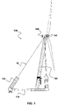
- FIG. 1 shows a side view of a preferably designed floating wind energy plant with a tower braced by means of cables designed particularly preferably according to the invention.
- the structure of the 1 illustrated floating wind turbine 100 is basically from the EP 3 019 740 B1 known.
- the floating wind energy installation 100 has a floating foundation 110 which has floating bodies 120 which are firmly connected to the foundation 110 and which can also be designed as an integral part of the foundation 110 .
- a tower (or mast) 130 is arranged on the foundation 110, on which a nacelle 140 carrying a rotor 150 is arranged.
- the mast 130 is braced by means of a plurality of ropes 10, which on the one hand on the top of the tower 130 or the nacelle 140 and on the other hand on the foundation 110 or the floating bodies 120 connected to the foundation 110 are arranged.
- the loads occurring in the area of the upper tower section are thus diverted into the foundation 110 of the floating wind turbine 100 by means of the cables 10 .
- a conical cable end sleeve 40 with a stop point 80 arranged at its base To attach the cables 10 to the tower 130 or the nacelle 140 or to the foundation 110, the cables, as shown in 2 shown, a conical cable end sleeve 40 with a stop point 80 arranged at its base.
- the structure of a particularly preferred rope is in 3 represented by an exploded view.
- the cable 10 consists of a large number of parallel, pultruded fiber-reinforced plastic profiles 20, which are surrounded by a UV-resistant and electrically insulating layer 30 and held together in a bundle.
- the end of the bundle is arranged within a cable end sleeve 40, electrically isolated from an electrically insulating insulation 50.
- the electrical insulation is necessary to prevent the lightning current from being discharged via the plastic profiles, which are made in particular of electrically conductive carbon fiber material.
- the end of the cable 10 within the cable end sleeve 40 is held by a conical sleeve insert 60 accommodating the ends of the plastic profiles 20 with at least one of its jackets.
- piercing opening 65 was added. A hardening resin is injected under pressure through the openings 65 into the sleeve insert, which resin casts the plastic profiles 20 spread apart by the spiked plate 70 closing the sleeve insert 60 together.
- Perforated plates 70', 70" shown are used, which preferably have a number of holes 74', 74" spaced apart from one another by webs 72', 72" corresponding to the number of plastic profiles 20 and which accommodate the plastic profiles 20 (individually) spread apart.
- the Holes 74′, 74′′ are sector-shaped and arranged uniformly, in particular symmetrically.
- the cable end sleeve 40 is closed at the end by the attachment point 80, with the attachment point 80 and the sleeve 40 preferably being connected to one another have a screw thread.
- the attachment point 80 there is preferably a ring 90 which closes the cable end sleeve 40 on the other side and surrounds the cable 10 and is also fastened to the cable end sleeve 40 by means of a thread.
- FIG. 4 shows two detailed views of the cable 10 arranged in the sleeve insert 60, in which the spread plastic profiles 20 as well as the filling openings 65 provided for injecting the resin can be clearly seen.
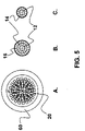
- figure 5 shows front views of the cable (A) arranged in the sleeve insert and cross sections of the cable (B, C) according to preferred embodiments of the invention.
- Figure 5A shows - as already 4 before - the spread plastic profiles 20 in the sleeve insert 60. All views figure 5 is the concentric arrangement of the parallel plastic profiles 20 in common.
- Figure 5B shows an arrangement with a core 12 with a plurality of sector-shaped plastic profiles 20, which is surrounded by a first circular ring 14 and a second circular ring 16, each with a plurality of circular-ring sector-shaped plastic profiles 20.
- the profiles 20 are each arranged in such a way that the abutting edges of plastic profiles 20 in the shape of a sector of a circular ring arranged adjacent in a circular ring 14, 16 are arranged between the abutting edges of plastic profiles 20 of the adjacent core 12 and/or a further circular ring 14, 16.
- Figure 5c shows an embodiment of a rope with a core 12 and only one circular ring 14 surrounding the core.
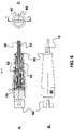
- FIG. 6 shows a detailed view of a particularly preferably designed rope in the area of the end sleeve as a longitudinal section (A), in plan view (B) and as a front view (C).
- the end of the cable 10 is most preferably disposed in a cable end sleeve 40, specifically in the socket insert 60 which is electrically isolated from the cable end sleeve 10 by the insulation 50.
- the spiked plate 70 or alternatively one of the perforated plates 70', 70"
- the spiked plate 70 which closes the sleeve insert 60 at its base and connected to one another by means of a hardened resin.
- the resin thus fills the free space of the cable end sleeve 40 and transmits the tensile loads occurring in the plastic profiles 20 via shear stresses into the resin and this in turn through compressive stresses into the cable end sleeve 40.
- the plastic profiles 20 are secured by the form fit mediated by the resin.
- the cable end sleeve 40 is closed at its base by a stop point 80 which can be connected to the cable end sleeve 40 in a particularly simple manner by means of appropriately provided threads.
- the conically tapering area of the cable end sleeve 40, from which the plastic profiles 20 of the cable 10 protrude, is closed by means of the ring 90, the gap between the cable 10 and the cable end sleeve 40 in a sealing manner.
Landscapes
- Engineering & Computer Science (AREA)
- General Engineering & Computer Science (AREA)
- Mechanical Engineering (AREA)
- Wind Motors (AREA)
- Ropes Or Cables (AREA)
Description
- Die Erfindung betrifft ein Seil. Insbesondere betrifft die Erfindung ein Seil zur Abspannung von Komponenten einer Windenergieanlage. Speziell betrifft die Erfindung ein Seil zur Abspannung des Turms einer Windenergieanlage und eine dieses Seil aufweisende Windenergieanlage.
- Seile zur Abspannung von Bauwerken, insbesondere von Masten aufweisenden Windenergieanlagen sind aus offenkundiger Vorbenutzung hinreichend bekannt. Derartige als Stahlseile ausgebildete Seile bestehen aus zusammengedrehten Drähten, die insbesondere zur Übertragung von im Bereich der Gondel auftretenden Lasten und deren Ableitung in das Fundament der Windenergieanlage verwendet werden.
- Zur Übertragung großer Lasten werden Paralleldrahtseile verwendet, die aus parallel nebeneinander liegenden, also nicht verdrehten oder geschlagenen Drähten hergestellt sind und eine gleichmäßige Beanspruchung der Seildrähte und eine über den Querschnitt des Drahtseils gleichmäßig verteilte Lastübertragung ermöglichen. Derartige Paralleldrahtseile sind jedoch sehr aufwändig, zumeist nur direkt am Ort der Verwendung herzustellen und eignen sich nicht zur Verwendung in einer Vielzahl von Anwendungen.
- Darüber hinaus sind Drahtseile allgemein sehr schwer. Aufgrund Ihres Gewichts haben sie eine niedrige Biegeeigenfrequenz und neigen bei entsprechender Anregung zu Schwingungen, die bei Windenergieanlagen zu schädlichen Auswirkungen führen. Es ist daher erforderlich, die Eigenfrequenz von Abspannseilen zu erhöhen, damit keine Anregung mehr stattfinden kann. Dafür muss das Verhältnis von Elastizitätsmodul des Abspannseils zu dessen spezifischer Masse maximiert werden.
- Alternativ ist es beispielsweise bekannt, Seile als ein Bündel aus Kunststoffprofilen auszubilden, wobei das Bündel aus einem Kern und wenigstens einem den Kern umgebenden Kreisring mit einer Mehrzahl von kreisringsektorförmig ausgebildeten Kunststoffprofilen gebildet ist. Derartige Seile sind beispielsweise aus der
WO 2208/129116 A1 , derGB 1 127 822 A JP H 09 132884 A WO 97/32710 A1 US 3 911 785 A verwiesen. - Aufgabe der Erfindung ist es jedenfalls, ein Seil zu schaffen, das eine über den Querschnitt verteilte gleichmäßige Lasteinleitung und -übertragung ermöglicht und verhältnismäßig einfach für eine Vielzahl von Anwendungen herzustellen ist.
- Diese Aufgabe wird erfindungsgemäß durch das Seil mit den Merkmalen von Anspruch 1 gelöst. Die Unteransprüche geben vorteilhafte Ausgestaltungen der Erfindung wieder.
- Grundgedanke der Erfindung ist es, ein Seil aus einer Mehrzahl von parallel angeordneten pultrudierten Kunststoffprofilen, also stranggezogenen Kunststoffprofilen herzustellen. Das Bereitstellen von Kunststoffprofilen, die bevorzugt jeweils eine identische Querschnittsfläche aufweisen, ermöglicht ein industrielles Herstellungsverfahren für ein Seil, das die Vorteile eines Paralleldrahtseils mit einem einfachen Herstellungsverfahren und einem gegenüber der Verwendung von Stahldraht geringerem Gewicht vereint.
- Insbesondere geht es bei der vorliegenden Erfindung vor allem darum, die bei der Verwendung an Windenergieanlagen auftretende Eigenfrequenz des Seils zu erhöhen die Seilstruktur so auszulegen, dass hohe Lasten in die Übertragungsstruktur eingeleitet werden können. Dieses wird insbesondere durch die Verwendung von einzelnen im Querschnitt kleinen Einzelprofilen erreicht, die zu einem Seil zusammengesetzt sind. So ist das Verhältnis aus Elastizitätsmodul zu spezifischem Streckengewicht bei der Verwendung von Kohlefaserseilen aus stranggezogenen Unidirektionalfasern bei im Verhältnis zu Stahlseilen gleicher Festigkeit um einen Faktor von ca. 5 höher.
- Erfindungsgemäß ist also ein Seil vorgesehen, das ein Bündel aus pultrudierten faserverstärkten Kunststoffprofilen aufweist, wobei das Bündel im Querschnitt als Kern mit einer Mehrzahl von sektorförmig ausgebildeten Kunststoffprofilen ausgebildet ist, der von wenigstens einem Kreisring mit einer Mehrzahl von kreisringsektorförmig ausgebildeten Kunststoffprofilen umgeben ist. Der zum Kern und zu den Kreisringen zusammengesetzten Profile bilden dabei jeweils gemeinsam einen kreisrunden Umfang aus.
- Insbesondere weisen der Kern und der wenigstens eine Kreisring jeweils eine geradzahlige Anzahl von Kunststoffprofilen auf.
- Das Seil weist bevorzugt ein Bündel von parallel angeordneten, pultrudierten faserverstärkten Kunststoffprofilen auf.
- Die Kunststoffprofile sind bevorzugt aus einem in einer Epoxidmatrix eingebetteten Kohlefaserwerkstoff gebildet.
- Dabei sind besonders bevorzugt die Stoßkanten von in einem Kreisring benachbart angeordneten kreisringsektorförmig ausgebildeten Kunststoffprofilen zwischen den Stoßkanten von Kunststoffprofilen des benachbarten Kerns und/oder eines weiteren Kreisrings angeordnet. Insbesondere unterscheidet sich die Anzahl der zu einem Ring zusammengesetzten Kunststoffprofile zwischen benachbarten Ringen. Speziell ist die Anzahl der zu einem Ring zusammengesetzten Kunststoffprofile eine Primzahl.
- Weisen die Kunststoffprofile nicht ohnehin bereits eine Oberfläche mit einer vorbestimmten Rauigkeit auf, ist weiter bevorzugt vorgesehen, dass die Oberflächen der Kunststoffprofile geschliffen sind und eine vorbestimmte Rauheit aufweisen.
- Das Bündel von Kunststoffprofilen ist bevorzugt von einem UV-beständigen und/oder wetterbeständigen und/oder elektrisch isolierenden Isolator umgeben. Dieser Isolator kann beispielsweise eine die Kunststoffprofile umgebende Beschichtung, insbesondere eine Beschichtung mit Polyurethan oder eine Beschichtung mit einem vernetzten Polyethylen (VPE) sein.
- Nach einer weiteren bevorzugten Ausgestaltung ist eine mit dem Seil verbundene, konisch ausgebildete Seilendhülse mit einem an der Basis angeordneten Anschlagpunkt vorgesehen, sodass das Seil problemlos an entsprechenden Verbindungsmitteln angeschlagen werden kann.
- Insbesondere weist der Anschlagpunkt ein mit einem an der Seilendhülse angeordneten Gewinde schraubendes Gewinde auf.
- Eine vorteilhafte Weiterbildung der Erfindung besteht darin, dass in der Seilendhülse eine die Kunststoffprofile radial auseinanderzwängende Stachelplatte vorgesehen ist, die bevorzugt aus einem elektrisch nicht-leitfähigem Material gebildet ist. Die Stachelplatte hält die einzelnen Kunststoffprofile in einem gleichmäßigen Abstand zueinander. Dieses dient dazu, eine optimale Verklebung der Profile untereinander und mit der Metallhülse zu erreichen.
- Insbesondere ist ein von der Seilendhülse aufgenommener und von der Stachelplatte verschlossener, die Enden der Kunststoffprofile aufnehmender kegelförmiger Hülseneinsatz mit wenigstens einer dessen Mantel durchstoßenden Öffnung vorgesehen.
- Alternativ zu einer Stachelplatte kann auch eine Lochplatte verwendet werden, die eine Mehrzahl von Löchern aufweist, die bevorzugt jeweils ein Kunststoffprofil aufnehmen. Auch durch diese Ausgestaltung kann eine Spreizung der Kunststoffprofile im Bereich der Seilendhülse erreicht werden.
- Weiter ist in die Seilendhülse ein die Kunststoffprofile im Bereich der Seilendhülse auseinanderzwängendes und stoffschlüssig miteinander verbindendes Harz eingebracht. Das Harz wird besonders bevorzugt durch die den Mantel des Hülseneinsatzes durchstoßenden Öffnungen zwischen die durch die Stachelplatte gespreizten Kunststoffprofile gebracht.
- Schließlich ist eine die Seilendhülse auskleidende, die Seilendhülse gegenüber den Kunststoffprofilen elektrisch isolierende Isolierung vorgesehen. Die Isolierung ist insbesondere dann notwendig, wenn die Kunststoffprofile einen elektrisch leitfähigen Kohlefaserwerkstoff aufweisen, um eine Blitzstromableitung über das Seil zu verhindern.
- Die Erfindung wird im Folgenden anhand eines in den beigefügten Zeichnungen dargestellten, besonders bevorzugt ausgestalteten Ausführungsbeispiels näher erläutert. Es zeigen:
- Fig. 1
- eine Seitenansicht einer bevorzugt ausgestalteten schwimmenden Windenergieanlage mit einem mittels gemäß der Erfindung besonders bevorzugt ausgestalteter Seile abgespannten Turm;
- Fig. 2
- eine Detailansicht der Windenergieanlage aus
Fig. 1 im Bereich der Gondel der Windenergieanlage; - Fig. 3
- eine Explosionsansicht eines besonders bevorzugt ausgestalteten Seils;
- Fig. 4
- Detailansichten (A, B) des im Hülseneinsatz angeordneten Seils;
- Fig. 5
- Frontalansichten des im Hülseneinsatz angeordneten Seils (A) und Querschnitte des Seils (B, C) nach bevorzugten Ausgestaltungen der Erfindung;
- Fig. 6
- eine Detailansicht eines besonders bevorzugt ausgestalteten Seils im Bereich der Endhülse als Längsschnitt (A), in Draufsicht (B) und als Frontalansicht (C); und
- Fig. 7
- eine Draufsicht auf zwei bevorzugt ausgestaltete Ausführungsbeispiele einer anstelle der Stachelplatte zu verwendenden Lochplatte zum Auseinanderzwängen der Kunststoffprofile im Bereich der Seilendhülse.
-
Fig. 1 zeigt eine Seitenansicht einer bevorzugt ausgestalteten schwimmenden Windenergieanlage mit einem mittels gemäß der Erfindung besonders bevorzugt ausgestalteter Seile abgespannten Turm. - Der Aufbau der in
Fig. 1 dargestellten schwimmenden Windenergieanlage 100 ist grundsätzlich aus derEP 3 019 740 B1 bekannt. Die schwimmende Windenergieanlage 100 weist ein schwimmendes Fundament 110 auf, das mit dem Fundament 110 fest verbundene Schwimmkörper 120 aufweist, die auch als integraler Bestandteil des Fundaments 110 ausgebildet sein können. Auf dem Fundament 110 ist ein Turm (oder Mast) 130 angeordnet, auf dem eine Gondel 140 angeordnet ist, die einen Rotor 150 trägt. - Der Mast 130 ist mittels einer Vielzahl von Seilen 10 abgespannt, die einerseits an der Oberseite des Turms 130 oder der Gondel 140 und andererseits am Fundament 110 bzw. den mit dem Fundament 110 verbundenen Schwimmkörpern 120 angeordnet sind. Die im Bereich des oberen Turmabschnitts auftretenden Lasten werden also mittels der Seile 10 in das Fundament 110 der schwimmenden Windenergieanlage 100 abgeleitet.
- Zur Befestigung der Seile 10 am Turm 130 bzw. der Gondel 140 bzw. am Fundament 110 weisen die Seile, wie in
Fig. 2 gezeigt, eine konisch ausgebildete Seilendhülse 40 mit einem an deren Basis angeordneten Anschlagpunkt 80 auf. - Der Aufbau eines besonders bevorzugt ausgestalteten Seils ist in
Fig. 3 mittels einer Explosionsansicht dargestellt. - Das Seil 10 besteht aus einer Vielzahl von parallel angeordneten, pultrudierten faserverstärkten Kunststoffprofilen 20, die von einer UV-beständigen und elektrisch isolierenden Schicht 30 umgeben und zu einem Bündel zusammengehalten sind.
- Das Ende des Bündels ist innerhalb einer Seilendhülse 40, von einer elektrisch isolierenden Isolierung 50 gegenüber dieser elektrisch isoliert angeordnet Die elektrische Isolierung ist notwendig, um eine Ableitung des Blitzstroms über die insbesondere aus elektrisch leitendem Kohlefaserwerkstoff hergestellten Kunststoffprofile zu verhindern. Insbesondere wird das Ende des Seils 10 innerhalb der Seilendhülse 40 von einem die Enden der Kunststoffprofile 20 aufnehmenden kegelförmigen Hülseneinsatz 60 mit wenigstens einer dessen Mantel. durchstoßenden Öffnung 65 aufgenommen. Durch die Öffnungen 65 wird ein härtendes Harz in den Hülseneinsatz unter Druck eingespritzt, das die durch die den Hülseneinsatz 60 verschließende Stachelplatte 70 gespreizten Kunststoffprofile 20 miteinander vergießt.
- Anstelle der Stachelplatte 70 kann auch eine der in
Fig. 7a und Fig. 7b gezeigten Lochplatten 70', 70" verwendet werden, die eine bevorzugt der Anzahl der Kunststoffprofile 20 entsprechende Anzahl von zueinander durch Stege 72', 72" beabstandeten Löchern 74', 74" aufweist, die die Kunststoffprofile 20 (einzeln) auseinander gespreizt aufnehmen. Die Löcher 74', 74" sind dabei sektorförmig und gleichmäßig, insbesondere symmetrisch angeordnet. - Schließlich wird die Seilendhülse 40 durch den Anschlagpunkt 80 stirnseitig verschlossen, wobei der Anschlagpunkt 80 und die Hülse 40 bevorzugt jeweils ein miteinander schraubendes Gewinde aufweisen. Dem Anschlagpunkt 80 gegenüberliegend ist bevorzugt noch ein die Seilendhülse 40 auf der anderen Seite verschließender Ring 90 vorgesehen, der das Seil 10 umgibt und ebenfalls mittels eines Gewindes an der Seilendhülse 40 befestig wird.
-
Fig. 4 zeigt zwei Detailansichten des im Hülseneinsatz 60 angeordneten Seils 10, bei dem die gespreizten Kunststoffprofile 20 wie auch die für das Einspritzen des Harzes vorgesehenen Einfüllöffnungen 65 deutlich zu erkennen sind. -
Fig. 5 zeigt Frontalansichten des im Hülseneinsatz angeordneten Seils (A) und Querschnitte des Seils (B, C) nach bevorzugten Ausgestaltungen der Erfindung.Fig. 5A zeigt - wie auch schonFig. 4 zuvor - die gespreizten Kunststoffprofile 20 im Hülseneinsatz 60. Allen Ansichten ausFig. 5 ist die konzentrische Anordnung der parallel geführten Kunststoffprofile 20 gemeinsam. -
Fig. 5B zeigt eine Anordnung mit einem Kern 12 mit einer Mehrzahl von sektorförmig ausgebildeten Kunststoffprofilen 20, der von einem ersten Kreisring 14 und einem zweiten Kreisring 16 mit jeweils einer Mehrzahl von kreisringsektorförmig ausgebildeten Kunststoffprofilen 20 umgeben ist. - Die Profile 20 sind jeweils so angeordnet, dass die Stoßkanten von in einem Kreisring 14, 16 benachbart angeordneten kreisringsektorförmig ausgebildeten Kunststoffprofilen 20 zwischen den Stoßkanten von Kunststoffprofilen 20 des benachbarten Kerns 12 und/oder eines weiteren Kreisrings 14, 16 angeordnet sind.
-
Fig. 5c zeigt eine Ausgestaltung eines Seils mit einem Kern 12 und lediglich einem den Kern umgebenden Kreisring 14. - Schließlich zeigt
Fig. 6 eine Detailansicht eines besonders bevorzugt ausgestalteten Seils im Bereich der Endhülse als Längsschnitt (A), in Draufsicht (B) und als Frontalansicht (C). - Wie zuvor beschrieben ist das Ende des Seils 10 besonders bevorzugt in einer Seilendhülse 40 angeordnet, speziell im Hülseneinsatz 60, der gegenüber der Seilendhülse 10 elektrisch durch die Isolierung 50 isoliert ist. Innerhalb des Hülseneinsatzes 60 sind die parallel geführten Kunststoffprofile 20 des Seils 10 durch die Stachelplatte 70 (oder alternativ eine der Lochplatten 70', 70"), die den Hülseneinsatz 60 an dessen Basis verschließt gespreizt und mittels eines ausgehärteten Harzes miteinander verbunden.
- Das Harz füllt somit den freien Raum der Seilendhülse 40 aus und überträgt die in den Kunststoffprofilen 20 auftretenden Zuglasten über Schubspannungen in das Harz und dieses wiederum durch Druckspannungen in die Seilendhülse 40. Dabei sind die Kunststoffprofile 20 durch den vom Harz vermittelten Formschluss gesichert.
- Die Seilendhülse 40 ist an deren Basis durch einen Anschlagpunkt 80 verschlossen, der besonders einfach mittels entsprechend vorgesehener Gewinde mit der Seilendhülse 40 verbunden werden kann. Der konisch zulaufende Bereich der Seilendhülse 40, aus dem die Kunststoffprofile 20 des Seil 10 heraustreten ist mittels des Rings 90, den Spalt zwischen Seil 10 und Seilendhülse 40 abdichtend verschlossen.
Claims (13)
- Seil (10) aufweisend ein Bündel aus pultrudierten faserverstärkten Kunststoffprofilen (20), wobei das Bündel im Querschnitt als Kern (12) und wenigstens einem den Kern (12) umgebenden Kreisring (14, 16) mit einer Mehrzahl von kreisringsektorförmig ausgebildeten Kunststoffprofilen (20) gebildet ist,
dadurch gekennzeichnet, dass
der Kern (12) aus einer Mehrzahl von im Querschnitt sektorförmig ausgebildeten Kunststoffprofilen (20) gebildet ist. - Seil (10) nach Anspruch 1, dadurch gekennzeichnet, dass der Kern (12) und der wenigstens eine Kreisring (14, 16) jeweils eine geradzahlige Anzahl von Kunststoffprofilen aufweisen.
- Seil (10) nach einem der Ansprüche 1 und 2, dadurch gekennzeichnet, dass die Stoßkanten von in einem Kreisring (14, 16) benachbart angeordneten kreisringsektorförmig ausgebildeten Kunststoffprofilen (20) zwischen den Stoßkanten von Kunststoffprofilen (20) des benachbarten Kerns (12) und/oder eines weiteren Kreisrings (14, 16) angeordnet sind.
- Seil (10) nach einem der vorhergehenden Ansprüche, dadurch gekennzeichnet, dass die Oberflächen der Kunststoffprofile (20) geschliffen sind.
- Seil (10) nach einem der vorhergehenden Ansprüche, dadurch gekennzeichnet, dass das Bündel von einem elektrisch isolierenden Isolator (30) umgeben ist.
- Seil (10) nach einem der vorhergehenden Ansprüche, gekennzeichnet durch eine konisch ausgebildete Seilendhülse (40) mit einem an der Basis angeordneten Anschlagpunkt (80).
- Seil (10) nach Anspruch 6, dadurch gekennzeichnet, dass der Anschlagpunkt (80) ein mit einem an der Seilendhülse (40) angeordneten Gewinde schraubendes Gewinde aufweist.
- Seil (10) nach einem der Ansprüche 6 und 7, dadurch gekennzeichnet, dass die Seilendhülse (40) eine die Kunststoffprofile (20) auseinanderzwängende Stachelplatte (70) aufweist.
- Seil (10) nach einem der Ansprüche 6 und 7, dadurch gekennzeichnet, dass die Seilendhülse (40) eine die Kunststoffprofile (20) auseinanderzwängende Lochplatte (70', 70") aufweist.
- Seil (10) nach einem der Ansprüche 8 und 9, gekennzeichnet durch einen von der Seilendhülse (40) aufgenommenen und von der Stachelplatte (70) oder der Lochplatte (70', 70") verschlossenen, die Enden der Kunststoffprofile (20) aufnehmenden kegelförmigen Hülseneinsatz (60) mit wenigstens einer dessen Mantel durchstoßenden Öffnung (65).
- Seil (10) nach einem der Ansprüche 6 bis 10, gekennzeichnet durch ein in der Seilendhülse (40) angeordnetes, die Kunststoffprofile (20) im Bereich der Seilendhülse (40) auseinanderzwängendes und stoffschlüssig miteinander verbindendes Harz.
- Seil (10) nach einem der Ansprüche 6 bis 11, gekennzeichnet durch eine die Seilendhülse (40) auskleidende, die Seilendhülse (40) gegenüber den Kunststoffprofilen (20) elektrisch isolierende Isolierung (50).
- Seil nach einem der vorhergehenden Ansprüche, dadurch gekennzeichnet, dass die Kunststoffprofile mit Kohlefasern verstärkt sind.
Applications Claiming Priority (2)
| Application Number | Priority Date | Filing Date | Title |
|---|---|---|---|
| DE102018113466.5A DE102018113466A1 (de) | 2018-06-06 | 2018-06-06 | Seil, insbesondere zur Abspannung von Komponenten einer Windenergieanlage |
| PCT/IB2019/000456 WO2019234491A1 (de) | 2018-06-06 | 2019-05-29 | Seil, insbesondere zur abspannung von komponenten einer windenergieanlage |
Publications (2)
| Publication Number | Publication Date |
|---|---|
| EP3775366A1 EP3775366A1 (de) | 2021-02-17 |
| EP3775366B1 true EP3775366B1 (de) | 2022-08-17 |
Family
ID=66999861
Family Applications (1)
| Application Number | Title | Priority Date | Filing Date |
|---|---|---|---|
| EP19732441.1A Active EP3775366B1 (de) | 2018-06-06 | 2019-05-29 | Seil, insbesondere zur abspannung von komponenten einer windenergieanlage |
Country Status (4)
| Country | Link |
|---|---|
| EP (1) | EP3775366B1 (de) |
| CN (1) | CN112236556B (de) |
| DE (1) | DE102018113466A1 (de) |
| WO (1) | WO2019234491A1 (de) |
Families Citing this family (1)
| Publication number | Priority date | Publication date | Assignee | Title |
|---|---|---|---|---|
| IT202000009814A1 (it) * | 2020-05-05 | 2021-11-05 | Maxspar S R L | Metodo di produzione di un terminale per sartie pretensionate in fibra di carbonio e prodotto così ottenuto |
Family Cites Families (17)
| Publication number | Priority date | Publication date | Assignee | Title |
|---|---|---|---|---|
| US3371476A (en) * | 1965-04-02 | 1968-03-05 | Gen Motors Corp | Glass plastic rope |
| US3911785A (en) * | 1974-01-18 | 1975-10-14 | Wall Ind Inc | Parallel yarn rope |
| SU842114A1 (ru) * | 1979-08-15 | 1981-06-30 | Предприятие П/Я В-8662 | Стальной канат |
| ATE192528T1 (de) * | 1994-04-25 | 2000-05-15 | Empa | Verankerung für hochleistungsfaserverbundwerkstoff-drähte |
| JPH09132884A (ja) * | 1995-11-07 | 1997-05-20 | Mitsubishi Rayon Co Ltd | 繊維強化樹脂ストランド |
| AUPN843596A0 (en) * | 1996-03-04 | 1996-03-28 | Pacific Dunlop Limited | Cable componentry |
| EP1334943B1 (de) * | 2000-07-27 | 2011-03-09 | Mitsubishi Denki Kabushiki Kaisha | Aufzugssystem |
| CN102139543B (zh) * | 2003-10-22 | 2016-08-03 | Ctc电缆公司 | 铝导体复合材料芯增强电缆及其制备方法 |
| FI125355B (fi) * | 2007-04-19 | 2015-09-15 | Kone Corp | Nostolaitteen köysi ja menetelmä nostolaitteen köyden valmistamiseksi |
| HU228364B1 (en) * | 2008-04-24 | 2013-03-28 | Pal Szaplonczay | Method and instalation for fabrication of heat resistant transmission line having a thermo softening core |
| CN201302833Y (zh) * | 2008-11-17 | 2009-09-02 | 中国电力科学研究院 | 复合芯和导线 |
| JP2013541443A (ja) * | 2010-09-17 | 2013-11-14 | スリーエム イノベイティブ プロパティズ カンパニー | 繊維強化ナノ粒子装填熱硬化性ポリマー複合体ワイヤ及びケーブル、並びに方法 |
| US20140030094A1 (en) * | 2011-04-11 | 2014-01-30 | Lm Wp Patent Holding A/S | Wind turbine blade having a root region with elongated fastening members provided with metal fibres |
| CH707004B1 (de) * | 2012-09-17 | 2016-07-29 | Fatzer Ag | Drahtseil sowie ein Zwischenstück für eine Spleissverbindung eines Drahtseils. |
| CN103306150B (zh) * | 2013-06-07 | 2016-01-20 | 南京诺尔泰复合材料设备制造有限公司 | 梯形截面的高强度复合材料绞线及其一步法制备方法 |
| ES2609467T3 (es) * | 2013-10-10 | 2017-04-20 | Kone Corporation | Cable para un dispositivo de elevación y ascensor |
| NO2776494T3 (de) | 2014-07-01 | 2018-09-29 |
-
2018
- 2018-06-06 DE DE102018113466.5A patent/DE102018113466A1/de not_active Withdrawn
-
2019
- 2019-05-29 EP EP19732441.1A patent/EP3775366B1/de active Active
- 2019-05-29 WO PCT/IB2019/000456 patent/WO2019234491A1/de not_active Ceased
- 2019-05-29 CN CN201980037913.1A patent/CN112236556B/zh active Active
Also Published As
| Publication number | Publication date |
|---|---|
| CN112236556B (zh) | 2022-09-27 |
| WO2019234491A1 (de) | 2019-12-12 |
| DE102018113466A1 (de) | 2019-12-12 |
| EP3775366A1 (de) | 2021-02-17 |
| CN112236556A (zh) | 2021-01-15 |
Similar Documents
| Publication | Publication Date | Title |
|---|---|---|
| EP3092357B1 (de) | Anordnung mit einem betonfundament und einem turm und verfahren zum errichten eines turms | |
| EP2729621B1 (de) | Anordnung zum abstützen eines zugglieds, insbesondere eines schrägseils, quer zu seiner längserstreckungsrichtung | |
| EP3092358B2 (de) | Windenergieanlage mit turm und fundament aus mehreren segmenten | |
| WO2005061813A1 (de) | Verankerung für vorgespannte und/oder belastete zugelemente | |
| EP3701107B1 (de) | Ringförmige konsole zum externen spannen eines turmsegments, externes spannsystem eines hybridturms, turmabschnitt eines hybridturms, hybridturm, windenergieanlage und montageverfahren eines externen spannsystems für einen hybridturm | |
| DE102011001250A1 (de) | Vorrichtung und Verfahren für den Übergang zwischen einem Stahlturmabschnitt und einem vorgespannten Betonturmabschnitt | |
| EP3924577B1 (de) | Hybrid-turmabschnitt, hybrid-turm für eine windenergieanlage sowie herstellungsverfahren | |
| EP3408532B1 (de) | Rotorblatt einer windenergieanlage mit holmgurt und herstellungsverfahren | |
| DE102010046518A1 (de) | Rotorblatt oder Rotorsegment für eine Windenergieanlage | |
| EP4491835A2 (de) | Turm mit konischen stahladapterelementen | |
| WO2020161091A1 (de) | Vorrichtung und verfahren zum entspannen einer spannlitze | |
| DE2753112B2 (de) | Verankerung eines gespannten Zugglieds für große Belastungen in einem Betonbauteil, z.B. eines Schrägseils einer Schrägseilbrücke | |
| DE102014100814B4 (de) | Turmbauwerk für eine Windenergieanlage | |
| DE102010046519A1 (de) | Rotorblatt oder Rotorblattsegment für eine Windenergieanlage | |
| EP3781811B1 (de) | Verfahren zum errichten eines windenergieanlagen-turms | |
| EP3775366B1 (de) | Seil, insbesondere zur abspannung von komponenten einer windenergieanlage | |
| EP3690187B1 (de) | Vorspannbarer verpressanker | |
| EP3891386B1 (de) | Verfahren zum vorspannen eines turms einer windenergieanlage | |
| EP1259679A1 (de) | Verankerung für ein vorgespanntes und/oder belastetes zugelement und ankerbüchse | |
| EP1873331A2 (de) | Freileitungsmast aus Schleuderbeton | |
| DE19901510A1 (de) | Fundament für oberirdische Türme | |
| DE2705483A1 (de) | Vorrichtung zur verankerung von zuggliedern aus hochfesten werkstoffen | |
| WO2018054418A1 (de) | Seil zur abspannung des turms einer windenergieanlage | |
| DE3234246A1 (de) | Kabel, insbesondere fuer schraegkabelbruecken aus spannbeton | |
| AT396912B (de) | Ein in der richtung seiner längsachse auf zug beanspruchbares bauteil |
Legal Events
| Date | Code | Title | Description |
|---|---|---|---|
| STAA | Information on the status of an ep patent application or granted ep patent |
Free format text: STATUS: UNKNOWN |
|
| STAA | Information on the status of an ep patent application or granted ep patent |
Free format text: STATUS: THE INTERNATIONAL PUBLICATION HAS BEEN MADE |
|
| PUAI | Public reference made under article 153(3) epc to a published international application that has entered the european phase |
Free format text: ORIGINAL CODE: 0009012 |
|
| STAA | Information on the status of an ep patent application or granted ep patent |
Free format text: STATUS: REQUEST FOR EXAMINATION WAS MADE |
|
| 17P | Request for examination filed |
Effective date: 20201110 |
|
| AK | Designated contracting states |
Kind code of ref document: A1 Designated state(s): AL AT BE BG CH CY CZ DE DK EE ES FI FR GB GR HR HU IE IS IT LI LT LU LV MC MK MT NL NO PL PT RO RS SE SI SK SM TR |
|
| AX | Request for extension of the european patent |
Extension state: BA ME |
|
| DAV | Request for validation of the european patent (deleted) | ||
| DAX | Request for extension of the european patent (deleted) | ||
| GRAP | Despatch of communication of intention to grant a patent |
Free format text: ORIGINAL CODE: EPIDOSNIGR1 |
|
| STAA | Information on the status of an ep patent application or granted ep patent |
Free format text: STATUS: GRANT OF PATENT IS INTENDED |
|
| GRAS | Grant fee paid |
Free format text: ORIGINAL CODE: EPIDOSNIGR3 |
|
| GRAA | (expected) grant |
Free format text: ORIGINAL CODE: 0009210 |
|
| STAA | Information on the status of an ep patent application or granted ep patent |
Free format text: STATUS: THE PATENT HAS BEEN GRANTED |
|
| INTG | Intention to grant announced |
Effective date: 20220622 |
|
| AK | Designated contracting states |
Kind code of ref document: B1 Designated state(s): AL AT BE BG CH CY CZ DE DK EE ES FI FR GB GR HR HU IE IS IT LI LT LU LV MC MK MT NL NO PL PT RO RS SE SI SK SM TR |
|
| REG | Reference to a national code |
Ref country code: CH Ref legal event code: EP |
|
| REG | Reference to a national code |
Ref country code: DE Ref legal event code: R096 Ref document number: 502019005348 Country of ref document: DE |
|
| REG | Reference to a national code |
Ref country code: IE Ref legal event code: FG4D Free format text: LANGUAGE OF EP DOCUMENT: GERMAN |
|
| REG | Reference to a national code |
Ref country code: AT Ref legal event code: REF Ref document number: 1512242 Country of ref document: AT Kind code of ref document: T Effective date: 20220915 |
|
| REG | Reference to a national code |
Ref country code: NL Ref legal event code: MP Effective date: 20220817 |
|
| REG | Reference to a national code |
Ref country code: LT Ref legal event code: MG9D |
|
| PG25 | Lapsed in a contracting state [announced via postgrant information from national office to epo] |
Ref country code: SE Free format text: LAPSE BECAUSE OF FAILURE TO SUBMIT A TRANSLATION OF THE DESCRIPTION OR TO PAY THE FEE WITHIN THE PRESCRIBED TIME-LIMIT Effective date: 20220817 Ref country code: RS Free format text: LAPSE BECAUSE OF FAILURE TO SUBMIT A TRANSLATION OF THE DESCRIPTION OR TO PAY THE FEE WITHIN THE PRESCRIBED TIME-LIMIT Effective date: 20220817 Ref country code: PT Free format text: LAPSE BECAUSE OF FAILURE TO SUBMIT A TRANSLATION OF THE DESCRIPTION OR TO PAY THE FEE WITHIN THE PRESCRIBED TIME-LIMIT Effective date: 20221219 Ref country code: NO Free format text: LAPSE BECAUSE OF FAILURE TO SUBMIT A TRANSLATION OF THE DESCRIPTION OR TO PAY THE FEE WITHIN THE PRESCRIBED TIME-LIMIT Effective date: 20221117 Ref country code: NL Free format text: LAPSE BECAUSE OF FAILURE TO SUBMIT A TRANSLATION OF THE DESCRIPTION OR TO PAY THE FEE WITHIN THE PRESCRIBED TIME-LIMIT Effective date: 20220817 Ref country code: LV Free format text: LAPSE BECAUSE OF FAILURE TO SUBMIT A TRANSLATION OF THE DESCRIPTION OR TO PAY THE FEE WITHIN THE PRESCRIBED TIME-LIMIT Effective date: 20220817 Ref country code: LT Free format text: LAPSE BECAUSE OF FAILURE TO SUBMIT A TRANSLATION OF THE DESCRIPTION OR TO PAY THE FEE WITHIN THE PRESCRIBED TIME-LIMIT Effective date: 20220817 Ref country code: FI Free format text: LAPSE BECAUSE OF FAILURE TO SUBMIT A TRANSLATION OF THE DESCRIPTION OR TO PAY THE FEE WITHIN THE PRESCRIBED TIME-LIMIT Effective date: 20220817 |
|
| PG25 | Lapsed in a contracting state [announced via postgrant information from national office to epo] |
Ref country code: PL Free format text: LAPSE BECAUSE OF FAILURE TO SUBMIT A TRANSLATION OF THE DESCRIPTION OR TO PAY THE FEE WITHIN THE PRESCRIBED TIME-LIMIT Effective date: 20220817 Ref country code: IS Free format text: LAPSE BECAUSE OF FAILURE TO SUBMIT A TRANSLATION OF THE DESCRIPTION OR TO PAY THE FEE WITHIN THE PRESCRIBED TIME-LIMIT Effective date: 20221217 Ref country code: HR Free format text: LAPSE BECAUSE OF FAILURE TO SUBMIT A TRANSLATION OF THE DESCRIPTION OR TO PAY THE FEE WITHIN THE PRESCRIBED TIME-LIMIT Effective date: 20220817 Ref country code: GR Free format text: LAPSE BECAUSE OF FAILURE TO SUBMIT A TRANSLATION OF THE DESCRIPTION OR TO PAY THE FEE WITHIN THE PRESCRIBED TIME-LIMIT Effective date: 20221118 |
|
| PG25 | Lapsed in a contracting state [announced via postgrant information from national office to epo] |
Ref country code: SM Free format text: LAPSE BECAUSE OF FAILURE TO SUBMIT A TRANSLATION OF THE DESCRIPTION OR TO PAY THE FEE WITHIN THE PRESCRIBED TIME-LIMIT Effective date: 20220817 Ref country code: RO Free format text: LAPSE BECAUSE OF FAILURE TO SUBMIT A TRANSLATION OF THE DESCRIPTION OR TO PAY THE FEE WITHIN THE PRESCRIBED TIME-LIMIT Effective date: 20220817 Ref country code: ES Free format text: LAPSE BECAUSE OF FAILURE TO SUBMIT A TRANSLATION OF THE DESCRIPTION OR TO PAY THE FEE WITHIN THE PRESCRIBED TIME-LIMIT Effective date: 20220817 Ref country code: DK Free format text: LAPSE BECAUSE OF FAILURE TO SUBMIT A TRANSLATION OF THE DESCRIPTION OR TO PAY THE FEE WITHIN THE PRESCRIBED TIME-LIMIT Effective date: 20220817 Ref country code: CZ Free format text: LAPSE BECAUSE OF FAILURE TO SUBMIT A TRANSLATION OF THE DESCRIPTION OR TO PAY THE FEE WITHIN THE PRESCRIBED TIME-LIMIT Effective date: 20220817 |
|
| REG | Reference to a national code |
Ref country code: DE Ref legal event code: R097 Ref document number: 502019005348 Country of ref document: DE |
|
| PG25 | Lapsed in a contracting state [announced via postgrant information from national office to epo] |
Ref country code: SK Free format text: LAPSE BECAUSE OF FAILURE TO SUBMIT A TRANSLATION OF THE DESCRIPTION OR TO PAY THE FEE WITHIN THE PRESCRIBED TIME-LIMIT Effective date: 20220817 Ref country code: EE Free format text: LAPSE BECAUSE OF FAILURE TO SUBMIT A TRANSLATION OF THE DESCRIPTION OR TO PAY THE FEE WITHIN THE PRESCRIBED TIME-LIMIT Effective date: 20220817 |
|
| PLBE | No opposition filed within time limit |
Free format text: ORIGINAL CODE: 0009261 |
|
| STAA | Information on the status of an ep patent application or granted ep patent |
Free format text: STATUS: NO OPPOSITION FILED WITHIN TIME LIMIT |
|
| PG25 | Lapsed in a contracting state [announced via postgrant information from national office to epo] |
Ref country code: AL Free format text: LAPSE BECAUSE OF FAILURE TO SUBMIT A TRANSLATION OF THE DESCRIPTION OR TO PAY THE FEE WITHIN THE PRESCRIBED TIME-LIMIT Effective date: 20220817 |
|
| 26N | No opposition filed |
Effective date: 20230519 |
|
| PG25 | Lapsed in a contracting state [announced via postgrant information from national office to epo] |
Ref country code: SI Free format text: LAPSE BECAUSE OF FAILURE TO SUBMIT A TRANSLATION OF THE DESCRIPTION OR TO PAY THE FEE WITHIN THE PRESCRIBED TIME-LIMIT Effective date: 20220817 |
|
| REG | Reference to a national code |
Ref country code: CH Ref legal event code: PL |
|
| PG25 | Lapsed in a contracting state [announced via postgrant information from national office to epo] |
Ref country code: MC Free format text: LAPSE BECAUSE OF FAILURE TO SUBMIT A TRANSLATION OF THE DESCRIPTION OR TO PAY THE FEE WITHIN THE PRESCRIBED TIME-LIMIT Effective date: 20220817 |
|
| REG | Reference to a national code |
Ref country code: BE Ref legal event code: MM Effective date: 20230531 |
|
| PG25 | Lapsed in a contracting state [announced via postgrant information from national office to epo] |
Ref country code: MC Free format text: LAPSE BECAUSE OF FAILURE TO SUBMIT A TRANSLATION OF THE DESCRIPTION OR TO PAY THE FEE WITHIN THE PRESCRIBED TIME-LIMIT Effective date: 20220817 Ref country code: LU Free format text: LAPSE BECAUSE OF NON-PAYMENT OF DUE FEES Effective date: 20230529 Ref country code: LI Free format text: LAPSE BECAUSE OF NON-PAYMENT OF DUE FEES Effective date: 20230531 Ref country code: CH Free format text: LAPSE BECAUSE OF NON-PAYMENT OF DUE FEES Effective date: 20230531 |
|
| PG25 | Lapsed in a contracting state [announced via postgrant information from national office to epo] |
Ref country code: IT Free format text: LAPSE BECAUSE OF FAILURE TO SUBMIT A TRANSLATION OF THE DESCRIPTION OR TO PAY THE FEE WITHIN THE PRESCRIBED TIME-LIMIT Effective date: 20220817 Ref country code: BE Free format text: LAPSE BECAUSE OF NON-PAYMENT OF DUE FEES Effective date: 20230531 |
|
| PG25 | Lapsed in a contracting state [announced via postgrant information from national office to epo] |
Ref country code: BG Free format text: LAPSE BECAUSE OF FAILURE TO SUBMIT A TRANSLATION OF THE DESCRIPTION OR TO PAY THE FEE WITHIN THE PRESCRIBED TIME-LIMIT Effective date: 20220817 |
|
| PG25 | Lapsed in a contracting state [announced via postgrant information from national office to epo] |
Ref country code: BG Free format text: LAPSE BECAUSE OF FAILURE TO SUBMIT A TRANSLATION OF THE DESCRIPTION OR TO PAY THE FEE WITHIN THE PRESCRIBED TIME-LIMIT Effective date: 20220817 |
|
| PGFP | Annual fee paid to national office [announced via postgrant information from national office to epo] |
Ref country code: DE Payment date: 20250213 Year of fee payment: 7 |
|
| PGFP | Annual fee paid to national office [announced via postgrant information from national office to epo] |
Ref country code: GB Payment date: 20250527 Year of fee payment: 7 |
|
| REG | Reference to a national code |
Ref country code: AT Ref legal event code: MM01 Ref document number: 1512242 Country of ref document: AT Kind code of ref document: T Effective date: 20240529 |
|
| PGFP | Annual fee paid to national office [announced via postgrant information from national office to epo] |
Ref country code: FR Payment date: 20250528 Year of fee payment: 7 |
|
| PG25 | Lapsed in a contracting state [announced via postgrant information from national office to epo] |
Ref country code: AT Free format text: LAPSE BECAUSE OF NON-PAYMENT OF DUE FEES Effective date: 20240529 |
|
| PG25 | Lapsed in a contracting state [announced via postgrant information from national office to epo] |
Ref country code: CY Free format text: LAPSE BECAUSE OF FAILURE TO SUBMIT A TRANSLATION OF THE DESCRIPTION OR TO PAY THE FEE WITHIN THE PRESCRIBED TIME-LIMIT; INVALID AB INITIO Effective date: 20190529 |
|
| PGFP | Annual fee paid to national office [announced via postgrant information from national office to epo] |
Ref country code: IE Payment date: 20250521 Year of fee payment: 7 |
|
| PG25 | Lapsed in a contracting state [announced via postgrant information from national office to epo] |
Ref country code: HU Free format text: LAPSE BECAUSE OF FAILURE TO SUBMIT A TRANSLATION OF THE DESCRIPTION OR TO PAY THE FEE WITHIN THE PRESCRIBED TIME-LIMIT; INVALID AB INITIO Effective date: 20190529 |
|
| PG25 | Lapsed in a contracting state [announced via postgrant information from national office to epo] |
Ref country code: TR Free format text: LAPSE BECAUSE OF FAILURE TO SUBMIT A TRANSLATION OF THE DESCRIPTION OR TO PAY THE FEE WITHIN THE PRESCRIBED TIME-LIMIT Effective date: 20220817 |
|
| PGFP | Annual fee paid to national office [announced via postgrant information from national office to epo] |
Ref country code: AT Payment date: 20260410 Year of fee payment: 5 |