EP3775366B1 - Câble, en particulier pour éléments de tension d'une éolienne - Google Patents
Câble, en particulier pour éléments de tension d'une éolienne Download PDFInfo
- Publication number
- EP3775366B1 EP3775366B1 EP19732441.1A EP19732441A EP3775366B1 EP 3775366 B1 EP3775366 B1 EP 3775366B1 EP 19732441 A EP19732441 A EP 19732441A EP 3775366 B1 EP3775366 B1 EP 3775366B1
- Authority
- EP
- European Patent Office
- Prior art keywords
- cable
- plastic profiles
- end sleeve
- cable end
- core
- Prior art date
- Legal status (The legal status is an assumption and is not a legal conclusion. Google has not performed a legal analysis and makes no representation as to the accuracy of the status listed.)
- Active
Links
Images


Classifications
-
- D—TEXTILES; PAPER
- D07—ROPES; CABLES OTHER THAN ELECTRIC
- D07B—ROPES OR CABLES IN GENERAL
- D07B5/00—Making ropes or cables from special materials or of particular form
- D07B5/10—Making ropes or cables from special materials or of particular form from strands of non-circular cross-section
-
- D—TEXTILES; PAPER
- D07—ROPES; CABLES OTHER THAN ELECTRIC
- D07B—ROPES OR CABLES IN GENERAL
- D07B1/00—Constructional features of ropes or cables
- D07B1/02—Ropes built-up from fibrous or filamentary material, e.g. of vegetable origin, of animal origin, regenerated cellulose, plastics
- D07B1/04—Ropes built-up from fibrous or filamentary material, e.g. of vegetable origin, of animal origin, regenerated cellulose, plastics with a core of fibres or filaments arranged parallel to the centre line
-
- F—MECHANICAL ENGINEERING; LIGHTING; HEATING; WEAPONS; BLASTING
- F16—ENGINEERING ELEMENTS AND UNITS; GENERAL MEASURES FOR PRODUCING AND MAINTAINING EFFECTIVE FUNCTIONING OF MACHINES OR INSTALLATIONS; THERMAL INSULATION IN GENERAL
- F16G—BELTS, CABLES, OR ROPES, PREDOMINANTLY USED FOR DRIVING PURPOSES; CHAINS; FITTINGS PREDOMINANTLY USED THEREFOR
- F16G11/00—Means for fastening cables or ropes to one another or to other objects; Caps or sleeves for fixing on cables or ropes
- F16G11/04—Means for fastening cables or ropes to one another or to other objects; Caps or sleeves for fixing on cables or ropes with wedging action, e.g. friction clamps
- F16G11/042—Means for fastening cables or ropes to one another or to other objects; Caps or sleeves for fixing on cables or ropes with wedging action, e.g. friction clamps using solidifying liquid material forming a wedge
-
- D—TEXTILES; PAPER
- D07—ROPES; CABLES OTHER THAN ELECTRIC
- D07B—ROPES OR CABLES IN GENERAL
- D07B2201/00—Ropes or cables
- D07B2201/20—Rope or cable components
- D07B2201/2015—Strands
- D07B2201/2016—Strands characterised by their cross-sectional shape
-
- D—TEXTILES; PAPER
- D07—ROPES; CABLES OTHER THAN ELECTRIC
- D07B—ROPES OR CABLES IN GENERAL
- D07B2201/00—Ropes or cables
- D07B2201/20—Rope or cable components
- D07B2201/2015—Strands
- D07B2201/2033—Parallel wires
-
- D—TEXTILES; PAPER
- D07—ROPES; CABLES OTHER THAN ELECTRIC
- D07B—ROPES OR CABLES IN GENERAL
- D07B2201/00—Ropes or cables
- D07B2201/20—Rope or cable components
- D07B2201/2015—Strands
- D07B2201/2046—Strands comprising fillers
-
- D—TEXTILES; PAPER
- D07—ROPES; CABLES OTHER THAN ELECTRIC
- D07B—ROPES OR CABLES IN GENERAL
- D07B2201/00—Ropes or cables
- D07B2201/20—Rope or cable components
- D07B2201/2047—Cores
- D07B2201/2052—Cores characterised by their structure
- D07B2201/2055—Cores characterised by their structure comprising filaments or fibers
- D07B2201/2056—Cores characterised by their structure comprising filaments or fibers arranged parallel to the axis
-
- D—TEXTILES; PAPER
- D07—ROPES; CABLES OTHER THAN ELECTRIC
- D07B—ROPES OR CABLES IN GENERAL
- D07B2201/00—Ropes or cables
- D07B2201/20—Rope or cable components
- D07B2201/2083—Jackets or coverings
- D07B2201/2087—Jackets or coverings being of the coated type
-
- D—TEXTILES; PAPER
- D07—ROPES; CABLES OTHER THAN ELECTRIC
- D07B—ROPES OR CABLES IN GENERAL
- D07B2205/00—Rope or cable materials
- D07B2205/20—Organic high polymers
- D07B2205/201—Polyolefins
-
- D—TEXTILES; PAPER
- D07—ROPES; CABLES OTHER THAN ELECTRIC
- D07B—ROPES OR CABLES IN GENERAL
- D07B2205/00—Rope or cable materials
- D07B2205/20—Organic high polymers
- D07B2205/206—Epoxy resins
-
- D—TEXTILES; PAPER
- D07—ROPES; CABLES OTHER THAN ELECTRIC
- D07B—ROPES OR CABLES IN GENERAL
- D07B2205/00—Rope or cable materials
- D07B2205/20—Organic high polymers
- D07B2205/2064—Polyurethane resins
-
- D—TEXTILES; PAPER
- D07—ROPES; CABLES OTHER THAN ELECTRIC
- D07B—ROPES OR CABLES IN GENERAL
- D07B2205/00—Rope or cable materials
- D07B2205/30—Inorganic materials
- D07B2205/3007—Carbon
-
- D—TEXTILES; PAPER
- D07—ROPES; CABLES OTHER THAN ELECTRIC
- D07B—ROPES OR CABLES IN GENERAL
- D07B5/00—Making ropes or cables from special materials or of particular form
- D07B5/002—Making parallel wire strands
-
- F—MECHANICAL ENGINEERING; LIGHTING; HEATING; WEAPONS; BLASTING
- F03—MACHINES OR ENGINES FOR LIQUIDS; WIND, SPRING, OR WEIGHT MOTORS; PRODUCING MECHANICAL POWER OR A REACTIVE PROPULSIVE THRUST, NOT OTHERWISE PROVIDED FOR
- F03D—WIND MOTORS
- F03D13/00—Assembly, mounting or commissioning of wind motors; Arrangements specially adapted for transporting wind motor components
- F03D13/20—Arrangements for mounting or supporting wind motors; Masts or towers for wind motors
- F03D13/25—Arrangements for mounting or supporting wind motors; Masts or towers for wind motors specially adapted for offshore installation
-
- F—MECHANICAL ENGINEERING; LIGHTING; HEATING; WEAPONS; BLASTING
- F05—INDEXING SCHEMES RELATING TO ENGINES OR PUMPS IN VARIOUS SUBCLASSES OF CLASSES F01-F04
- F05B—INDEXING SCHEME RELATING TO WIND, SPRING, WEIGHT, INERTIA OR LIKE MOTORS, TO MACHINES OR ENGINES FOR LIQUIDS COVERED BY SUBCLASSES F03B, F03D AND F03G
- F05B2240/00—Components
- F05B2240/90—Mounting on supporting structures or systems
- F05B2240/91—Mounting on supporting structures or systems on a stationary structure
- F05B2240/917—Mounting on supporting structures or systems on a stationary structure attached to cables
-
- Y—GENERAL TAGGING OF NEW TECHNOLOGICAL DEVELOPMENTS; GENERAL TAGGING OF CROSS-SECTIONAL TECHNOLOGIES SPANNING OVER SEVERAL SECTIONS OF THE IPC; TECHNICAL SUBJECTS COVERED BY FORMER USPC CROSS-REFERENCE ART COLLECTIONS [XRACs] AND DIGESTS
- Y02—TECHNOLOGIES OR APPLICATIONS FOR MITIGATION OR ADAPTATION AGAINST CLIMATE CHANGE
- Y02E—REDUCTION OF GREENHOUSE GAS [GHG] EMISSIONS, RELATED TO ENERGY GENERATION, TRANSMISSION OR DISTRIBUTION
- Y02E10/00—Energy generation through renewable energy sources
- Y02E10/70—Wind energy
- Y02E10/72—Wind turbines with rotation axis in wind direction
Definitions
- the invention relates to a rope.
- the invention relates to a rope for bracing components of a wind power plant.
- the invention relates to a rope for anchoring the tower of a wind energy plant and a wind energy plant having this rope.
- Cables for anchoring structures are sufficiently well known from prior public use. Cables of this type, designed as steel cables, consist of twisted wires that are used in particular to transmit loads occurring in the area of the nacelle and to divert them into the foundation of the wind turbine.
- parallel wire ropes are used, which are made of wires lying parallel to one another, i.e. not twisted or twisted, and which enable the rope wires to be evenly stressed and the load to be transferred evenly over the cross-section of the wire rope.
- parallel wire ropes are very complex, mostly only to be produced directly at the place of use and are not suitable for use in a large number of applications.
- wire ropes are generally very heavy. Due to their weight, they have a low natural bending frequency and, when excited, tend to vibrate, which can have harmful effects on wind turbines. It is therefore necessary to increase the natural frequency of guy ropes so that excitation can no longer take place. To do this, the ratio of the modulus of elasticity of the guy rope to its specific mass must be maximized.
- cables as a bundle of plastic profiles, the bundle being formed from a core and at least one circular ring surrounding the core with a plurality of plastic profiles designed in the shape of a sector of a circular ring.
- ropes are, for example, from WO 2208/129116 A1 , the GB1 127 822 A , the JP H 09 132884 A and the WO 97/32710 A1 known.
- U.S. 3,911,785 A referred.
- the object of the invention is to create a rope that enables load introduction and transmission that is distributed uniformly over the cross section and is relatively easy to manufacture for a large number of applications.
- the basic idea of the invention is to produce a cable from a plurality of pultruded plastic profiles, ie extruded plastic profiles, arranged in parallel.
- the provision of plastic profiles, each of which preferably has an identical cross-sectional area, enables an industrial manufacturing process for a rope that combines the advantages of a parallel wire rope with a simple manufacturing process and a lower weight compared to using steel wire.
- the present invention is primarily concerned with increasing the natural frequency of the rope that occurs when it is used in wind energy installations, and designing the rope structure in such a way that high loads can be introduced into the transmission structure. This is achieved in particular through the use of individual profiles with a small cross section, which are combined to form a cable.
- the ratio of the modulus of elasticity to the specific line weight is higher by a factor of approx. 5 when using carbon fiber ropes made from extruded unidirectional fibers with the same strength as steel ropes.
- a rope which has a bundle of pultruded fiber-reinforced plastic profiles, the bundle being designed in cross section as a core with a plurality of plastic profiles designed in the shape of sectors, which is surrounded by at least one circular ring with a plurality of plastic profiles designed in the shape of circular ring sectors.
- the profiles combined to form the core and the circular rings together form a circular circumference.
- the core and the at least one circular ring each have an even number of plastic profiles.
- the rope preferably has a bundle of parallel, pultruded fiber-reinforced plastic profiles.
- the plastic profiles are preferably formed from a carbon fiber material embedded in an epoxy matrix.
- the abutting edges of plastic profiles which are arranged adjacent in a circular ring and are configured in the shape of a sector of a circular ring are particularly preferably arranged between the abutting edges of plastic profiles of the adjacent core and/or a further circular ring.
- the number of plastic profiles assembled into a ring differs between adjacent rings.
- the number of plastic profiles assembled to form a ring is a prime number.
- the plastic profiles do not already have a surface with a predetermined roughness, it is further preferably provided that the surfaces of the plastic profiles are ground and have a predetermined roughness.
- the bundle of plastic profiles is preferably surrounded by a UV-resistant and/or weather-resistant and/or electrically insulating insulator.
- This insulator can, for example, be a coating surrounding the plastic profiles, in particular a coating with polyurethane or a coating with a crosslinked polyethylene (VPE).
- a conical cable end sleeve connected to the cable is provided with an attachment point arranged on the base, so that the cable can be attached to corresponding connection means without any problems.
- the attachment point has a thread which screws with a thread arranged on the cable end sleeve.
- An advantageous development of the invention consists in that a spiked plate, which forces the plastic profiles radially apart and is preferably formed from an electrically non-conductive material, is provided in the cable end sleeve.
- the spiked plate keeps the individual plastic profiles at an even distance from each other. This serves to achieve optimal bonding of the profiles to each other and to the metal sleeve.
- a conical sleeve insert which is held by the cable end sleeve and closed by the spiked plate and which holds the ends of the plastic profiles, is provided with at least one opening penetrating its jacket.
- a perforated plate can also be used, which has a plurality of holes, each of which preferably accommodates a plastic profile. A spreading of the plastic profiles in the area of the cable end sleeve can also be achieved with this configuration.
- a resin is introduced into the cable end sleeve that forces the plastic profiles apart in the area of the cable end sleeve and connects them with one another in a materially bonded manner.
- the resin is particularly preferably brought through the openings penetrating the jacket of the sleeve insert between the plastic profiles spread by the spiked plate.
- insulation is provided that lines the cable end sleeve and electrically isolates the cable end sleeve from the plastic profiles. Insulation is necessary in particular if the plastic profiles have an electrically conductive carbon fiber material in order to prevent lightning current being discharged via the cable.
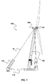
- FIG. 1 shows a side view of a preferably designed floating wind energy plant with a tower braced by means of cables designed particularly preferably according to the invention.
- the structure of the 1 illustrated floating wind turbine 100 is basically from the EP 3 019 740 B1 known.
- the floating wind energy installation 100 has a floating foundation 110 which has floating bodies 120 which are firmly connected to the foundation 110 and which can also be designed as an integral part of the foundation 110 .
- a tower (or mast) 130 is arranged on the foundation 110, on which a nacelle 140 carrying a rotor 150 is arranged.
- the mast 130 is braced by means of a plurality of ropes 10, which on the one hand on the top of the tower 130 or the nacelle 140 and on the other hand on the foundation 110 or the floating bodies 120 connected to the foundation 110 are arranged.
- the loads occurring in the area of the upper tower section are thus diverted into the foundation 110 of the floating wind turbine 100 by means of the cables 10 .
- a conical cable end sleeve 40 with a stop point 80 arranged at its base To attach the cables 10 to the tower 130 or the nacelle 140 or to the foundation 110, the cables, as shown in 2 shown, a conical cable end sleeve 40 with a stop point 80 arranged at its base.
- the structure of a particularly preferred rope is in 3 represented by an exploded view.
- the cable 10 consists of a large number of parallel, pultruded fiber-reinforced plastic profiles 20, which are surrounded by a UV-resistant and electrically insulating layer 30 and held together in a bundle.
- the end of the bundle is arranged within a cable end sleeve 40, electrically isolated from an electrically insulating insulation 50.
- the electrical insulation is necessary to prevent the lightning current from being discharged via the plastic profiles, which are made in particular of electrically conductive carbon fiber material.
- the end of the cable 10 within the cable end sleeve 40 is held by a conical sleeve insert 60 accommodating the ends of the plastic profiles 20 with at least one of its jackets.
- piercing opening 65 was added. A hardening resin is injected under pressure through the openings 65 into the sleeve insert, which resin casts the plastic profiles 20 spread apart by the spiked plate 70 closing the sleeve insert 60 together.
- Perforated plates 70', 70" shown are used, which preferably have a number of holes 74', 74" spaced apart from one another by webs 72', 72" corresponding to the number of plastic profiles 20 and which accommodate the plastic profiles 20 (individually) spread apart.
- the Holes 74′, 74′′ are sector-shaped and arranged uniformly, in particular symmetrically.
- the cable end sleeve 40 is closed at the end by the attachment point 80, with the attachment point 80 and the sleeve 40 preferably being connected to one another have a screw thread.
- the attachment point 80 there is preferably a ring 90 which closes the cable end sleeve 40 on the other side and surrounds the cable 10 and is also fastened to the cable end sleeve 40 by means of a thread.
- FIG. 4 shows two detailed views of the cable 10 arranged in the sleeve insert 60, in which the spread plastic profiles 20 as well as the filling openings 65 provided for injecting the resin can be clearly seen.
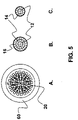
- figure 5 shows front views of the cable (A) arranged in the sleeve insert and cross sections of the cable (B, C) according to preferred embodiments of the invention.
- Figure 5A shows - as already 4 before - the spread plastic profiles 20 in the sleeve insert 60. All views figure 5 is the concentric arrangement of the parallel plastic profiles 20 in common.
- Figure 5B shows an arrangement with a core 12 with a plurality of sector-shaped plastic profiles 20, which is surrounded by a first circular ring 14 and a second circular ring 16, each with a plurality of circular-ring sector-shaped plastic profiles 20.
- the profiles 20 are each arranged in such a way that the abutting edges of plastic profiles 20 in the shape of a sector of a circular ring arranged adjacent in a circular ring 14, 16 are arranged between the abutting edges of plastic profiles 20 of the adjacent core 12 and/or a further circular ring 14, 16.
- Figure 5c shows an embodiment of a rope with a core 12 and only one circular ring 14 surrounding the core.
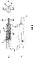
- FIG. 6 shows a detailed view of a particularly preferably designed rope in the area of the end sleeve as a longitudinal section (A), in plan view (B) and as a front view (C).
- the end of the cable 10 is most preferably disposed in a cable end sleeve 40, specifically in the socket insert 60 which is electrically isolated from the cable end sleeve 10 by the insulation 50.
- the spiked plate 70 or alternatively one of the perforated plates 70', 70"
- the spiked plate 70 which closes the sleeve insert 60 at its base and connected to one another by means of a hardened resin.
- the resin thus fills the free space of the cable end sleeve 40 and transmits the tensile loads occurring in the plastic profiles 20 via shear stresses into the resin and this in turn through compressive stresses into the cable end sleeve 40.
- the plastic profiles 20 are secured by the form fit mediated by the resin.
- the cable end sleeve 40 is closed at its base by a stop point 80 which can be connected to the cable end sleeve 40 in a particularly simple manner by means of appropriately provided threads.
- the conically tapering area of the cable end sleeve 40, from which the plastic profiles 20 of the cable 10 protrude, is closed by means of the ring 90, the gap between the cable 10 and the cable end sleeve 40 in a sealing manner.
Landscapes
- Engineering & Computer Science (AREA)
- General Engineering & Computer Science (AREA)
- Mechanical Engineering (AREA)
- Wind Motors (AREA)
- Ropes Or Cables (AREA)
Claims (13)
- Câble (10) comportant un faisceau de profilés pultrudés (20) en matière plastique renforcés par des fibres, le faisceau étant formé en section transversale sous la forme d'un noyau (12) et au moins un bague annulaire (14, 16) entourant le noyau (12) et comprenant une pluralité de profilés en matière plastique (20) réalisés en forme de secteur circulairement annulaire,
caractérisée en ce que
le noyau (12) est formé par une pluralité de profilée en matière plastique (20) réalisés en forme de secteur en section transversale. - Câble (10) selon la revendication 1, caractérisée en ce que le noyau (12) et l'au moins un bague annulaire (14, 16) comportent respectivement un nombre pair de profilés en matière plastique.
- Câble (10) selon l'une quelconque des revendications 1 et 2, caractérisée en ce que les bords d'impact de profilés en matière plastique (20) réalisés en forme de secteur circulairement annulaire disposés adjacents les uns aux autres dans un bague annulaire (14, 16) sont disposés entre les bords d'impact de profilés en matière plastique (20) du noyau (12) adjacent et/ou d'un autre bague annulaire (14, 16).
- Câble (10) selon l'une quelconque des revendications précédentes, caractérisée en ce que la surface des profilés en matière plastique (20) est poncée.
- Câble (10) selon l'une quelconque des revendications précédentes, caractérisée en ce que le faisceau est entouré par un isolateur (30) isolant électriquement.
- Câble (10) selon l'une quelconque des revendications précédentes, caractérisée par un manchon d'extrémité de câble (40) de forme conique comprenant un point de butée (80) disposé à la base.
- Câble (10) selon la revendication 6, caractérisée en ce que le point de butée (80) comporte un filetage se vissant avec un filetage disposé sur le manchon d'extrémité de câble (40).
- Câble (10) selon l'une quelconque des revendications 6 et 7, caractérisée en ce que le manchon d'extrémité de câble (40) comporte une plaque à aiguilles (70) écartant les profilés en matière plastique (20) les uns des autres.
- Câble (10) selon l'une quelconque des revendications 6 et 7, caractérisée en ce que le manchon d'extrémité de câble (40) comporte une plaque perforée (70',70") écartant les profilés en matière plastique (20) les uns des autres.
- Câble (10) selon l'une quelconque des revendications 8 et 9, caractérisée par un insert de douille (60) conique reçu par le manchon d'extrémité de câble (40) et fermé par la plaque à aiguille (70) ou la plaque perforée (70', 70") recevant les extrémités des profilés en matière plastique (20) comprenant au moins une ouverture (65) traversant son enveloppe.
- Câble (10) selon l'une quelconque des revendications 6 à 10, caractérisée par une résine disposée dans le manchon d'extrémité de câble (40), écartant et connectant les uns aux autres par complémentarité de forme les profilés en matière plastique (20) dans la zone du manchon d'extrémité de câble (40).
- Câble (10) selon l'une quelconque des revendications 6 à 11, caractérisée par une isolation (50) enveloppant le manchon d'extrémité de câble (40), isolant électriquement le manchon d'extrémité de câble (40) par rapport au profilés en matière plastique (20).
- Câble selon l'une quelconque des revendications précédentes, caractérisée en ce que les profilés en matière plastique sont renforcés par des fibres de carbone.
Applications Claiming Priority (2)
| Application Number | Priority Date | Filing Date | Title |
|---|---|---|---|
| DE102018113466.5A DE102018113466A1 (de) | 2018-06-06 | 2018-06-06 | Seil, insbesondere zur Abspannung von Komponenten einer Windenergieanlage |
| PCT/IB2019/000456 WO2019234491A1 (fr) | 2018-06-06 | 2019-05-29 | Câble, en particulier pour éléments de tension d'une éolienne |
Publications (2)
| Publication Number | Publication Date |
|---|---|
| EP3775366A1 EP3775366A1 (fr) | 2021-02-17 |
| EP3775366B1 true EP3775366B1 (fr) | 2022-08-17 |
Family
ID=66999861
Family Applications (1)
| Application Number | Title | Priority Date | Filing Date |
|---|---|---|---|
| EP19732441.1A Active EP3775366B1 (fr) | 2018-06-06 | 2019-05-29 | Câble, en particulier pour éléments de tension d'une éolienne |
Country Status (4)
| Country | Link |
|---|---|
| EP (1) | EP3775366B1 (fr) |
| CN (1) | CN112236556B (fr) |
| DE (1) | DE102018113466A1 (fr) |
| WO (1) | WO2019234491A1 (fr) |
Families Citing this family (1)
| Publication number | Priority date | Publication date | Assignee | Title |
|---|---|---|---|---|
| IT202000009814A1 (it) * | 2020-05-05 | 2021-11-05 | Maxspar S R L | Metodo di produzione di un terminale per sartie pretensionate in fibra di carbonio e prodotto così ottenuto |
Family Cites Families (17)
| Publication number | Priority date | Publication date | Assignee | Title |
|---|---|---|---|---|
| US3371476A (en) * | 1965-04-02 | 1968-03-05 | Gen Motors Corp | Glass plastic rope |
| US3911785A (en) * | 1974-01-18 | 1975-10-14 | Wall Ind Inc | Parallel yarn rope |
| SU842114A1 (ru) * | 1979-08-15 | 1981-06-30 | Предприятие П/Я В-8662 | Стальной канат |
| ATE192528T1 (de) * | 1994-04-25 | 2000-05-15 | Empa | Verankerung für hochleistungsfaserverbundwerkstoff-drähte |
| JPH09132884A (ja) * | 1995-11-07 | 1997-05-20 | Mitsubishi Rayon Co Ltd | 繊維強化樹脂ストランド |
| AUPN843596A0 (en) * | 1996-03-04 | 1996-03-28 | Pacific Dunlop Limited | Cable componentry |
| EP1334943B1 (fr) * | 2000-07-27 | 2011-03-09 | Mitsubishi Denki Kabushiki Kaisha | Systeme elevateur |
| CN102139543B (zh) * | 2003-10-22 | 2016-08-03 | Ctc电缆公司 | 铝导体复合材料芯增强电缆及其制备方法 |
| FI125355B (fi) * | 2007-04-19 | 2015-09-15 | Kone Corp | Nostolaitteen köysi ja menetelmä nostolaitteen köyden valmistamiseksi |
| HU228364B1 (en) * | 2008-04-24 | 2013-03-28 | Pal Szaplonczay | Method and instalation for fabrication of heat resistant transmission line having a thermo softening core |
| CN201302833Y (zh) * | 2008-11-17 | 2009-09-02 | 中国电力科学研究院 | 复合芯和导线 |
| JP2013541443A (ja) * | 2010-09-17 | 2013-11-14 | スリーエム イノベイティブ プロパティズ カンパニー | 繊維強化ナノ粒子装填熱硬化性ポリマー複合体ワイヤ及びケーブル、並びに方法 |
| US20140030094A1 (en) * | 2011-04-11 | 2014-01-30 | Lm Wp Patent Holding A/S | Wind turbine blade having a root region with elongated fastening members provided with metal fibres |
| CH707004B1 (de) * | 2012-09-17 | 2016-07-29 | Fatzer Ag | Drahtseil sowie ein Zwischenstück für eine Spleissverbindung eines Drahtseils. |
| CN103306150B (zh) * | 2013-06-07 | 2016-01-20 | 南京诺尔泰复合材料设备制造有限公司 | 梯形截面的高强度复合材料绞线及其一步法制备方法 |
| ES2609467T3 (es) * | 2013-10-10 | 2017-04-20 | Kone Corporation | Cable para un dispositivo de elevación y ascensor |
| NO2776494T3 (fr) | 2014-07-01 | 2018-09-29 |
-
2018
- 2018-06-06 DE DE102018113466.5A patent/DE102018113466A1/de not_active Withdrawn
-
2019
- 2019-05-29 EP EP19732441.1A patent/EP3775366B1/fr active Active
- 2019-05-29 WO PCT/IB2019/000456 patent/WO2019234491A1/fr not_active Ceased
- 2019-05-29 CN CN201980037913.1A patent/CN112236556B/zh active Active
Also Published As
| Publication number | Publication date |
|---|---|
| CN112236556B (zh) | 2022-09-27 |
| WO2019234491A1 (fr) | 2019-12-12 |
| DE102018113466A1 (de) | 2019-12-12 |
| EP3775366A1 (fr) | 2021-02-17 |
| CN112236556A (zh) | 2021-01-15 |
Similar Documents
| Publication | Publication Date | Title |
|---|---|---|
| EP3092357B1 (fr) | Ensemble comprenant une fondation en béton et une tour et procédé d'érection d'une tour | |
| EP2729621B1 (fr) | Système destiné à supporter un organe de traction, notamment un hauban, dans un sens perpendiculaire à son étendue longitudinale | |
| EP3092358B2 (fr) | Éolienne pourvue d'un mât et d'une embase composée de plusieurs segments | |
| WO2005061813A1 (fr) | Ancrage pour elements de traction precontraints et/ou sollicites | |
| EP3701107B1 (fr) | Console annulaire destinée à la contrainte externe d'un segment de tour, système de contrainte externe d'une tour hybride, section de tour d'une tour hybride, tour hybride, éolienne et procédé de montage d'un système de contrainte externe pour une tour hybride | |
| DE102011001250A1 (de) | Vorrichtung und Verfahren für den Übergang zwischen einem Stahlturmabschnitt und einem vorgespannten Betonturmabschnitt | |
| EP3924577B1 (fr) | Segment de tour hybride, tour hybride pour une éolienne et procédé de fabrication | |
| EP3408532B1 (fr) | Pale de rotor d'une éolienne avec bride de longeron et son procédé de fabrication | |
| DE102010046518A1 (de) | Rotorblatt oder Rotorsegment für eine Windenergieanlage | |
| EP4491835A2 (fr) | Tour pourvue d'éléments adaptateurs en acier coniques | |
| WO2020161091A1 (fr) | Dispositif et procédé pour détendre un fil de précontrainte | |
| DE2753112B2 (de) | Verankerung eines gespannten Zugglieds für große Belastungen in einem Betonbauteil, z.B. eines Schrägseils einer Schrägseilbrücke | |
| DE102014100814B4 (de) | Turmbauwerk für eine Windenergieanlage | |
| DE102010046519A1 (de) | Rotorblatt oder Rotorblattsegment für eine Windenergieanlage | |
| EP3781811B1 (fr) | Procédé permettant d'ériger une tour d'éolienne | |
| EP3775366B1 (fr) | Câble, en particulier pour éléments de tension d'une éolienne | |
| EP3690187B1 (fr) | Ancre de sol capable d'être pré-contrainte | |
| EP3891386B1 (fr) | Procédé pour réaliser un préserrage du mât d'une éolienne | |
| EP1259679A1 (fr) | Ancrage pour element de traction precontraint et/ou charge et boite d'ancrage | |
| EP1873331A2 (fr) | Pylône de ligne électrique aérienne en béton centrifugé | |
| DE19901510A1 (de) | Fundament für oberirdische Türme | |
| DE2705483A1 (de) | Vorrichtung zur verankerung von zuggliedern aus hochfesten werkstoffen | |
| WO2018054418A1 (fr) | Câble de haubannage pour mât d'éolienne | |
| DE3234246A1 (de) | Kabel, insbesondere fuer schraegkabelbruecken aus spannbeton | |
| AT396912B (de) | Ein in der richtung seiner längsachse auf zug beanspruchbares bauteil |
Legal Events
| Date | Code | Title | Description |
|---|---|---|---|
| STAA | Information on the status of an ep patent application or granted ep patent |
Free format text: STATUS: UNKNOWN |
|
| STAA | Information on the status of an ep patent application or granted ep patent |
Free format text: STATUS: THE INTERNATIONAL PUBLICATION HAS BEEN MADE |
|
| PUAI | Public reference made under article 153(3) epc to a published international application that has entered the european phase |
Free format text: ORIGINAL CODE: 0009012 |
|
| STAA | Information on the status of an ep patent application or granted ep patent |
Free format text: STATUS: REQUEST FOR EXAMINATION WAS MADE |
|
| 17P | Request for examination filed |
Effective date: 20201110 |
|
| AK | Designated contracting states |
Kind code of ref document: A1 Designated state(s): AL AT BE BG CH CY CZ DE DK EE ES FI FR GB GR HR HU IE IS IT LI LT LU LV MC MK MT NL NO PL PT RO RS SE SI SK SM TR |
|
| AX | Request for extension of the european patent |
Extension state: BA ME |
|
| DAV | Request for validation of the european patent (deleted) | ||
| DAX | Request for extension of the european patent (deleted) | ||
| GRAP | Despatch of communication of intention to grant a patent |
Free format text: ORIGINAL CODE: EPIDOSNIGR1 |
|
| STAA | Information on the status of an ep patent application or granted ep patent |
Free format text: STATUS: GRANT OF PATENT IS INTENDED |
|
| GRAS | Grant fee paid |
Free format text: ORIGINAL CODE: EPIDOSNIGR3 |
|
| GRAA | (expected) grant |
Free format text: ORIGINAL CODE: 0009210 |
|
| STAA | Information on the status of an ep patent application or granted ep patent |
Free format text: STATUS: THE PATENT HAS BEEN GRANTED |
|
| INTG | Intention to grant announced |
Effective date: 20220622 |
|
| AK | Designated contracting states |
Kind code of ref document: B1 Designated state(s): AL AT BE BG CH CY CZ DE DK EE ES FI FR GB GR HR HU IE IS IT LI LT LU LV MC MK MT NL NO PL PT RO RS SE SI SK SM TR |
|
| REG | Reference to a national code |
Ref country code: CH Ref legal event code: EP |
|
| REG | Reference to a national code |
Ref country code: DE Ref legal event code: R096 Ref document number: 502019005348 Country of ref document: DE |
|
| REG | Reference to a national code |
Ref country code: IE Ref legal event code: FG4D Free format text: LANGUAGE OF EP DOCUMENT: GERMAN |
|
| REG | Reference to a national code |
Ref country code: AT Ref legal event code: REF Ref document number: 1512242 Country of ref document: AT Kind code of ref document: T Effective date: 20220915 |
|
| REG | Reference to a national code |
Ref country code: NL Ref legal event code: MP Effective date: 20220817 |
|
| REG | Reference to a national code |
Ref country code: LT Ref legal event code: MG9D |
|
| PG25 | Lapsed in a contracting state [announced via postgrant information from national office to epo] |
Ref country code: SE Free format text: LAPSE BECAUSE OF FAILURE TO SUBMIT A TRANSLATION OF THE DESCRIPTION OR TO PAY THE FEE WITHIN THE PRESCRIBED TIME-LIMIT Effective date: 20220817 Ref country code: RS Free format text: LAPSE BECAUSE OF FAILURE TO SUBMIT A TRANSLATION OF THE DESCRIPTION OR TO PAY THE FEE WITHIN THE PRESCRIBED TIME-LIMIT Effective date: 20220817 Ref country code: PT Free format text: LAPSE BECAUSE OF FAILURE TO SUBMIT A TRANSLATION OF THE DESCRIPTION OR TO PAY THE FEE WITHIN THE PRESCRIBED TIME-LIMIT Effective date: 20221219 Ref country code: NO Free format text: LAPSE BECAUSE OF FAILURE TO SUBMIT A TRANSLATION OF THE DESCRIPTION OR TO PAY THE FEE WITHIN THE PRESCRIBED TIME-LIMIT Effective date: 20221117 Ref country code: NL Free format text: LAPSE BECAUSE OF FAILURE TO SUBMIT A TRANSLATION OF THE DESCRIPTION OR TO PAY THE FEE WITHIN THE PRESCRIBED TIME-LIMIT Effective date: 20220817 Ref country code: LV Free format text: LAPSE BECAUSE OF FAILURE TO SUBMIT A TRANSLATION OF THE DESCRIPTION OR TO PAY THE FEE WITHIN THE PRESCRIBED TIME-LIMIT Effective date: 20220817 Ref country code: LT Free format text: LAPSE BECAUSE OF FAILURE TO SUBMIT A TRANSLATION OF THE DESCRIPTION OR TO PAY THE FEE WITHIN THE PRESCRIBED TIME-LIMIT Effective date: 20220817 Ref country code: FI Free format text: LAPSE BECAUSE OF FAILURE TO SUBMIT A TRANSLATION OF THE DESCRIPTION OR TO PAY THE FEE WITHIN THE PRESCRIBED TIME-LIMIT Effective date: 20220817 |
|
| PG25 | Lapsed in a contracting state [announced via postgrant information from national office to epo] |
Ref country code: PL Free format text: LAPSE BECAUSE OF FAILURE TO SUBMIT A TRANSLATION OF THE DESCRIPTION OR TO PAY THE FEE WITHIN THE PRESCRIBED TIME-LIMIT Effective date: 20220817 Ref country code: IS Free format text: LAPSE BECAUSE OF FAILURE TO SUBMIT A TRANSLATION OF THE DESCRIPTION OR TO PAY THE FEE WITHIN THE PRESCRIBED TIME-LIMIT Effective date: 20221217 Ref country code: HR Free format text: LAPSE BECAUSE OF FAILURE TO SUBMIT A TRANSLATION OF THE DESCRIPTION OR TO PAY THE FEE WITHIN THE PRESCRIBED TIME-LIMIT Effective date: 20220817 Ref country code: GR Free format text: LAPSE BECAUSE OF FAILURE TO SUBMIT A TRANSLATION OF THE DESCRIPTION OR TO PAY THE FEE WITHIN THE PRESCRIBED TIME-LIMIT Effective date: 20221118 |
|
| PG25 | Lapsed in a contracting state [announced via postgrant information from national office to epo] |
Ref country code: SM Free format text: LAPSE BECAUSE OF FAILURE TO SUBMIT A TRANSLATION OF THE DESCRIPTION OR TO PAY THE FEE WITHIN THE PRESCRIBED TIME-LIMIT Effective date: 20220817 Ref country code: RO Free format text: LAPSE BECAUSE OF FAILURE TO SUBMIT A TRANSLATION OF THE DESCRIPTION OR TO PAY THE FEE WITHIN THE PRESCRIBED TIME-LIMIT Effective date: 20220817 Ref country code: ES Free format text: LAPSE BECAUSE OF FAILURE TO SUBMIT A TRANSLATION OF THE DESCRIPTION OR TO PAY THE FEE WITHIN THE PRESCRIBED TIME-LIMIT Effective date: 20220817 Ref country code: DK Free format text: LAPSE BECAUSE OF FAILURE TO SUBMIT A TRANSLATION OF THE DESCRIPTION OR TO PAY THE FEE WITHIN THE PRESCRIBED TIME-LIMIT Effective date: 20220817 Ref country code: CZ Free format text: LAPSE BECAUSE OF FAILURE TO SUBMIT A TRANSLATION OF THE DESCRIPTION OR TO PAY THE FEE WITHIN THE PRESCRIBED TIME-LIMIT Effective date: 20220817 |
|
| REG | Reference to a national code |
Ref country code: DE Ref legal event code: R097 Ref document number: 502019005348 Country of ref document: DE |
|
| PG25 | Lapsed in a contracting state [announced via postgrant information from national office to epo] |
Ref country code: SK Free format text: LAPSE BECAUSE OF FAILURE TO SUBMIT A TRANSLATION OF THE DESCRIPTION OR TO PAY THE FEE WITHIN THE PRESCRIBED TIME-LIMIT Effective date: 20220817 Ref country code: EE Free format text: LAPSE BECAUSE OF FAILURE TO SUBMIT A TRANSLATION OF THE DESCRIPTION OR TO PAY THE FEE WITHIN THE PRESCRIBED TIME-LIMIT Effective date: 20220817 |
|
| PLBE | No opposition filed within time limit |
Free format text: ORIGINAL CODE: 0009261 |
|
| STAA | Information on the status of an ep patent application or granted ep patent |
Free format text: STATUS: NO OPPOSITION FILED WITHIN TIME LIMIT |
|
| PG25 | Lapsed in a contracting state [announced via postgrant information from national office to epo] |
Ref country code: AL Free format text: LAPSE BECAUSE OF FAILURE TO SUBMIT A TRANSLATION OF THE DESCRIPTION OR TO PAY THE FEE WITHIN THE PRESCRIBED TIME-LIMIT Effective date: 20220817 |
|
| 26N | No opposition filed |
Effective date: 20230519 |
|
| PG25 | Lapsed in a contracting state [announced via postgrant information from national office to epo] |
Ref country code: SI Free format text: LAPSE BECAUSE OF FAILURE TO SUBMIT A TRANSLATION OF THE DESCRIPTION OR TO PAY THE FEE WITHIN THE PRESCRIBED TIME-LIMIT Effective date: 20220817 |
|
| REG | Reference to a national code |
Ref country code: CH Ref legal event code: PL |
|
| PG25 | Lapsed in a contracting state [announced via postgrant information from national office to epo] |
Ref country code: MC Free format text: LAPSE BECAUSE OF FAILURE TO SUBMIT A TRANSLATION OF THE DESCRIPTION OR TO PAY THE FEE WITHIN THE PRESCRIBED TIME-LIMIT Effective date: 20220817 |
|
| REG | Reference to a national code |
Ref country code: BE Ref legal event code: MM Effective date: 20230531 |
|
| PG25 | Lapsed in a contracting state [announced via postgrant information from national office to epo] |
Ref country code: MC Free format text: LAPSE BECAUSE OF FAILURE TO SUBMIT A TRANSLATION OF THE DESCRIPTION OR TO PAY THE FEE WITHIN THE PRESCRIBED TIME-LIMIT Effective date: 20220817 Ref country code: LU Free format text: LAPSE BECAUSE OF NON-PAYMENT OF DUE FEES Effective date: 20230529 Ref country code: LI Free format text: LAPSE BECAUSE OF NON-PAYMENT OF DUE FEES Effective date: 20230531 Ref country code: CH Free format text: LAPSE BECAUSE OF NON-PAYMENT OF DUE FEES Effective date: 20230531 |
|
| PG25 | Lapsed in a contracting state [announced via postgrant information from national office to epo] |
Ref country code: IT Free format text: LAPSE BECAUSE OF FAILURE TO SUBMIT A TRANSLATION OF THE DESCRIPTION OR TO PAY THE FEE WITHIN THE PRESCRIBED TIME-LIMIT Effective date: 20220817 Ref country code: BE Free format text: LAPSE BECAUSE OF NON-PAYMENT OF DUE FEES Effective date: 20230531 |
|
| PG25 | Lapsed in a contracting state [announced via postgrant information from national office to epo] |
Ref country code: BG Free format text: LAPSE BECAUSE OF FAILURE TO SUBMIT A TRANSLATION OF THE DESCRIPTION OR TO PAY THE FEE WITHIN THE PRESCRIBED TIME-LIMIT Effective date: 20220817 |
|
| PG25 | Lapsed in a contracting state [announced via postgrant information from national office to epo] |
Ref country code: BG Free format text: LAPSE BECAUSE OF FAILURE TO SUBMIT A TRANSLATION OF THE DESCRIPTION OR TO PAY THE FEE WITHIN THE PRESCRIBED TIME-LIMIT Effective date: 20220817 |
|
| PGFP | Annual fee paid to national office [announced via postgrant information from national office to epo] |
Ref country code: DE Payment date: 20250213 Year of fee payment: 7 |
|
| PGFP | Annual fee paid to national office [announced via postgrant information from national office to epo] |
Ref country code: GB Payment date: 20250527 Year of fee payment: 7 |
|
| REG | Reference to a national code |
Ref country code: AT Ref legal event code: MM01 Ref document number: 1512242 Country of ref document: AT Kind code of ref document: T Effective date: 20240529 |
|
| PGFP | Annual fee paid to national office [announced via postgrant information from national office to epo] |
Ref country code: FR Payment date: 20250528 Year of fee payment: 7 |
|
| PG25 | Lapsed in a contracting state [announced via postgrant information from national office to epo] |
Ref country code: AT Free format text: LAPSE BECAUSE OF NON-PAYMENT OF DUE FEES Effective date: 20240529 |
|
| PG25 | Lapsed in a contracting state [announced via postgrant information from national office to epo] |
Ref country code: CY Free format text: LAPSE BECAUSE OF FAILURE TO SUBMIT A TRANSLATION OF THE DESCRIPTION OR TO PAY THE FEE WITHIN THE PRESCRIBED TIME-LIMIT; INVALID AB INITIO Effective date: 20190529 |
|
| PGFP | Annual fee paid to national office [announced via postgrant information from national office to epo] |
Ref country code: IE Payment date: 20250521 Year of fee payment: 7 |
|
| PG25 | Lapsed in a contracting state [announced via postgrant information from national office to epo] |
Ref country code: HU Free format text: LAPSE BECAUSE OF FAILURE TO SUBMIT A TRANSLATION OF THE DESCRIPTION OR TO PAY THE FEE WITHIN THE PRESCRIBED TIME-LIMIT; INVALID AB INITIO Effective date: 20190529 |
|
| PG25 | Lapsed in a contracting state [announced via postgrant information from national office to epo] |
Ref country code: TR Free format text: LAPSE BECAUSE OF FAILURE TO SUBMIT A TRANSLATION OF THE DESCRIPTION OR TO PAY THE FEE WITHIN THE PRESCRIBED TIME-LIMIT Effective date: 20220817 |
|
| PGFP | Annual fee paid to national office [announced via postgrant information from national office to epo] |
Ref country code: AT Payment date: 20260410 Year of fee payment: 5 |