EP3776033B1 - Tétine de poussée-traction flexible et corps de sertissage pour connecteur de fibre optique - Google Patents
Tétine de poussée-traction flexible et corps de sertissage pour connecteur de fibre optique Download PDFInfo
- Publication number
- EP3776033B1 EP3776033B1 EP19782181.2A EP19782181A EP3776033B1 EP 3776033 B1 EP3776033 B1 EP 3776033B1 EP 19782181 A EP19782181 A EP 19782181A EP 3776033 B1 EP3776033 B1 EP 3776033B1
- Authority
- EP
- European Patent Office
- Prior art keywords
- boot
- fiber optic
- crimp body
- optic connector
- engagement member
- Prior art date
- Legal status (The legal status is an assumption and is not a legal conclusion. Google has not performed a legal analysis and makes no representation as to the accuracy of the status listed.)
- Active
Links
Images


Classifications
-
- G—PHYSICS
- G02—OPTICS
- G02B—OPTICAL ELEMENTS, SYSTEMS OR APPARATUS
- G02B6/00—Light guides; Structural details of arrangements comprising light guides and other optical elements, e.g. couplings
- G02B6/24—Coupling light guides
- G02B6/36—Mechanical coupling means
- G02B6/38—Mechanical coupling means having fibre to fibre mating means
- G02B6/3807—Dismountable connectors, i.e. comprising plugs
- G02B6/381—Dismountable connectors, i.e. comprising plugs of the ferrule type, e.g. fibre ends embedded in ferrules, connecting a pair of fibres
- G02B6/3825—Dismountable connectors, i.e. comprising plugs of the ferrule type, e.g. fibre ends embedded in ferrules, connecting a pair of fibres with an intermediate part, e.g. adapter, receptacle, linking two plugs
-
- G—PHYSICS
- G02—OPTICS
- G02B—OPTICAL ELEMENTS, SYSTEMS OR APPARATUS
- G02B6/00—Light guides; Structural details of arrangements comprising light guides and other optical elements, e.g. couplings
- G02B6/24—Coupling light guides
- G02B6/36—Mechanical coupling means
- G02B6/38—Mechanical coupling means having fibre to fibre mating means
- G02B6/3807—Dismountable connectors, i.e. comprising plugs
- G02B6/3887—Anchoring optical cables to connector housings, e.g. strain relief features
- G02B6/38875—Protection from bending or twisting
-
- G—PHYSICS
- G02—OPTICS
- G02B—OPTICAL ELEMENTS, SYSTEMS OR APPARATUS
- G02B6/00—Light guides; Structural details of arrangements comprising light guides and other optical elements, e.g. couplings
- G02B6/24—Coupling light guides
- G02B6/36—Mechanical coupling means
- G02B6/38—Mechanical coupling means having fibre to fibre mating means
- G02B6/3807—Dismountable connectors, i.e. comprising plugs
- G02B6/3887—Anchoring optical cables to connector housings, e.g. strain relief features
- G02B6/3888—Protection from over-extension or over-compression
-
- G—PHYSICS
- G02—OPTICS
- G02B—OPTICAL ELEMENTS, SYSTEMS OR APPARATUS
- G02B6/00—Light guides; Structural details of arrangements comprising light guides and other optical elements, e.g. couplings
- G02B6/24—Coupling light guides
- G02B6/36—Mechanical coupling means
- G02B6/38—Mechanical coupling means having fibre to fibre mating means
- G02B6/3807—Dismountable connectors, i.e. comprising plugs
- G02B6/389—Dismountable connectors, i.e. comprising plugs characterised by the method of fastening connecting plugs and sockets, e.g. screw- or nut-lock, snap-in, bayonet type
- G02B6/3893—Push-pull type, e.g. snap-in, push-on
-
- G—PHYSICS
- G02—OPTICS
- G02B—OPTICAL ELEMENTS, SYSTEMS OR APPARATUS
- G02B6/00—Light guides; Structural details of arrangements comprising light guides and other optical elements, e.g. couplings
- G02B6/24—Coupling light guides
- G02B6/36—Mechanical coupling means
- G02B6/38—Mechanical coupling means having fibre to fibre mating means
- G02B6/3807—Dismountable connectors, i.e. comprising plugs
- G02B6/3869—Mounting ferrules to connector body, i.e. plugs
- G02B6/387—Connector plugs comprising two complementary members, e.g. shells, caps, covers, locked together
-
- G—PHYSICS
- G02—OPTICS
- G02B—OPTICAL ELEMENTS, SYSTEMS OR APPARATUS
- G02B6/00—Light guides; Structural details of arrangements comprising light guides and other optical elements, e.g. couplings
- G02B6/24—Coupling light guides
- G02B6/36—Mechanical coupling means
- G02B6/38—Mechanical coupling means having fibre to fibre mating means
- G02B6/3807—Dismountable connectors, i.e. comprising plugs
- G02B6/3895—Dismountable connectors, i.e. comprising plugs identification of connection, e.g. right plug to the right socket or full engagement of the mating parts
-
- G—PHYSICS
- G02—OPTICS
- G02B—OPTICAL ELEMENTS, SYSTEMS OR APPARATUS
- G02B6/00—Light guides; Structural details of arrangements comprising light guides and other optical elements, e.g. couplings
- G02B6/24—Coupling light guides
- G02B6/36—Mechanical coupling means
- G02B6/40—Mechanical coupling means having fibre bundle mating means
- G02B6/406—Mechanical coupling means having fibre bundle mating means of the ferrule type, connecting a plurality of pairs of ferrules
Definitions
- the invention relates to a combination of a boot and a crimp body suitable to be used for a fiber optic connector having a housing, at least two fiber optic ferrules, and a spring push.
- Fiber optic connectors and the locations where they are installed, are becoming smaller, requiring a higher density application.
- the fiber optic connectors have been reducedin size such that a person can not easily grasp individual fiber optic connectors mounted in a receptacle in the high density areas.
- Adjacent fiber optic connectors are generally located too close to allow manual insertion and removal of a single fiber optic connector using the connector's outer housing as intended, particularly, when used in higher density applications.
- Some solutions to the smaller areas include push-pull tabs or projections connected to the fiber optic connector, either as an additional component or as anintegral part of the fiber optic connector, usually the outer housing.
- boot While a boot may be used for pushing a fiber optic connector into a receptacle, they are generally not intended to be used to remove a fiber optic connector.
- the boot is generally used for strain relief of the optical fibers secured within the fiber optic connectors.In many connectors, the boot simply cannot be used for fiber optic connector removal as theboot is not attached to the appropriate structures, such as the outer housing.
- the typical boot on a fiber optic connector can not convey the polarity of the fiber optic connector to which it is attached.
- US 8,764,308 B2 describes several embodiments of a duplex clip assembly for use in aiding the insertion and removal of a pair of LC fiber optic connectors.
- the assembly includes a duplex housing, a housing cover, a crimp sleeve, a boot and a pair of LC connectors.
- US 8,152,385 B2 relates to a duplex fiber optic assemblies suitable for polarity reversal and methods therefor.
- the present invention is therefore directed to a combination of a boot and a crimp body that can be used with a fiberoptic connector to insert into and remove from a receptacle.
- the boot can also be detached from a portion of the fiber optic connector and reinstalled in a different configuration to identify a polarity of the fiber optic connector.
- a problem-free detachment of the boot from the crimp body should be possible with constructionally simply means.
- the present invention is directed to a combination of a boot and a crimp body suitable to be used for a fiber optic connector having a housing, at least two fiber optic ferrules, and a spring push:
- the boot comprising: a center portion having a front end and a back end, a first longitudinal opening extending between the front end and the back end is adapted to receive a portion of the crimp body anda fiber optic cable; a back portion attached to the center portion and extending away from the front end of the center portion, the back portion defining a second longitudinal opening that is in communication with the first longitudinal opening, the back portion having grasping portions to allow a user to push and pull on the boot;
- the boot further comprising a front extension portion connected to the center portion and engageable with the fiber optic connector, the front extension portion extending forward and beyond the front end of the center portion and having at least one latch to engage a receptacle;
- the crimp body comprising a front portion configured to be disposed at least partially in the housing;
- the first engagement member comprises one of at least one projection and at least one notch and the second engagement member comprises the other of at least one projection and at least one notch, the at least one notch has a length to allow for movement of the at least one projection within the at least one notch without becoming unattached.
- the at least one projection includes two projections and the at least one notch comprises two notches.
- the at least one notch includes a forward facing surface and the at least one projection includes a rearward facing surface such that pulling on the boot causes the rearward facing surface toengage the forward facing surface.
- pulling onthe boot causes the first engagement member to slide relative to the second engagement member thereby pulling the front extension rearwardly releasing the fiber optic connector from the receptacle.
- front or forward means that direction where the fiber optic connector would meet with another fiber optic connector or device
- rear or “rearward” is used to mean the direction from which the optical fibers enter into the fiber-optic ferrule or fiber optic connector.
- front is that part of the fiber optic connector on the left side of FIG. 1 and “forward” is out and to the left.
- Rear or “back” is that part of the fiber optic connector that is on the right side of the page and “rearward” and “backward” is toward the right.
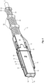
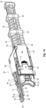
- the fiber optic connector 100 may include a housing 102, fiber optic ferrules 104 (which may be included in a ferrule assembly as disclosed in PCT/2018/066523), a crimp body 106, a crimp ring and heat shrink tube 108, a front extension 110 that is a part of strain relief boot 112.
- the crimp body 106, the front extension 110, and a strain relief boot 112 are the focus of this application.
- the front extension 110 also functions as a push-pull mechanism or latch component, whereby the front extension 110 has at least one latch and more preferably two latches 114, 116 on a latch body 118 that engage a receptacle (such as an adapter and/or a carrier) if used with the present invention.
- the front extension 110 also functions as a polarity key for the fiber optic connector 100. As described in more detail below, the fiber optic connector 100 can only be inserted into a receptacle in one orientation with the front extension 110 installed on the fiber optic connector 100.
- the housing 102 is symmetric about a longitudinal axis A through the fiber optic connector 100.
- the fiber optic connector 100 could be inserted into a receptacle in at least two ways.
- the front extension 110 prevents the fiber optic connector 100 from being inserted in all but one way - thereby giving it a polarity function.
- the housing 102 has a main body 120 extending between a front end 122 and a rear end 124, and has an opening 126 extending therebetween. See also FIGS. 6 and 7 .
- the fiber optic ferrules 104 are disposed within the opening 126 and have their front faces (for mating with other fiber optic ferrules) adjacent the front end 122.
- the crimp body 106 is also at least partially disposed within the opening 126 at the rear end 124 of the housing 102.
- the outside of the housing 102 has many features that are integral to its use.
- First are the top surface 130 and the bottom surface 132.
- the top and bottom surfaces 130,132 are preferably the same.
- Extending from the rear end 124 towards the front end 122 of the housing 102 on both the top surface 130 and the bottom surface 132 is a rail receiving portion 134.
- the rail receiving portion 134 as illustrated does not extend the entire length of the housing 102, but it could extend farther along the length of the housing 102 than shown in the figures if so desired.
- the rail receiving portion 134 has a stop surface 136 at the end of the rail receiving portion 134.
- the front extension 110 will make use of the stop surface 136 when the fiber optic connector 100 is inserted into or removed from various structures as discussed in more detail below.
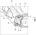
- the rail receiving portion 134 has a central portion 138 and two lobe sections 140, one lobe on each side of the central portion 138. As a result, the rail receiving portion 134 looks like part of a profile of a dog bone. This configuration matches that of the bottom surface of the front extension 110 (latch component or push-pull mechanism) to form a sliding dove-tail configuration. See FIG. 7 . Other configurations are possible, such as, for example, a cap with undercuts (essentially an umbrella or a T-shape configuration).
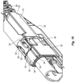
- the fiber optic connector 100 also includes the crimp body 106.
- the crimp body 106 has a front portion 150 that is designed to interact and connect with the housing 102 and a spring push (not shown) that is used in conjunction with the fiber optic ferrules 104 in the opening 126 thereof.
- the crimp body 106 has a central portion 152 that fits against the rear end 124 of the housing 102.
- the central portion 152 has a first portion 154 that includes a rail receiving portion 158 on both a top side 154 and a bottom side 156.
- the rail receiving portion 158 has a central portion 160 and two lobe sections 162, one lobe on each side of the central portion 160 that matches the same structure 134 on the housing 102 to engage the front extension 110.
- the central portion 152 has a second, more rearward portion 170 that include two notches 172 on both the top side 154 and the bottom side 156.
- At a rearward end 174 of each of the four notches 172 are forward facing surfaces 176 to engage latches on the boot 112.
- the notches 172 and the forward facing surfaces 176 are involved in the connection of the boot 112 (and the front extension 110) to the crimp body 106 and the housing 102 as explained below.
- the crimp body 106 has a rear portion 180 that extends behind the central portion 152 and the housing 102 and provides an outer surface 182 to receive a crimp band (e.g., crimp ring and heat shrink tube) therearound. Extending through the crimp body 106 is an opening 184 through which optical fibers/optical fiber cable can pass between the fiber optic ferrules 104 and the boot 112.
- a crimp band e.g., crimp ring and heat shrink tube
- the design will allow for the use of a crimp band to attach the aramid yarn from a fiber optic cable, the crimp band is optional and the fiber optic connector will work without a crimp band when the aramid yarn is not present. Further, when the crimp band is not used, the crimp body would require the outer surface 182.
- the boot 112 includes the front extension 110, a center portion 200 that is disposed between the front extension 110 and a ribbed back portion 202. It should be noted that the front extension 110 is preferably an integral part of the center portion 200, but it could be removably attached to the center portion 200 and still fall within the scope of the present invention.
- the center portion 200 has a front end 204 and a back end 206 with a first longitudinal opening 208 extending throughout the center portion 200.
- the first longitudinal opening 208 receives at least a portion of the crimp body 106, including at least the rear portion 180 that extends behind the central portion 152 and the outer surface 182 with the crimp band.
- the first longitudinal opening 208 also receives the rearward portion 170 of the central portion 152 of the crimp body 106 as well as the notches 172 and the forward facing surfaces 176. See FIG. 9 .
- the center portion 200 also has sides 210 that help to define the first longitudinal opening 208.
- the sides 210 may also have cut-outs 212 that receive a portion 214 of the crimp body 106.
- the cooperation between the cut-outs 212 and the portion 214 of the crimp body 106 assist in alignment and the integrity of the combination of the crimp body 106 and the center portion 200.
- the sides 210 could be solid and cover the overlapping portion of the crimp body 106. See, e.g., FIG. 16 .
- the projections or latches 220 are disposed within the two notches 172 on one of the top side 154 or bottom side 156, depending on the orientation of the boot 112.
- the projections or latches 220 are farthest from the forward facing surfaces 176 that at least partially define the two notches 172. See FIG. 9 .
- the front end 204 of the center portion 200 should be touching the first portion 154 of the central portion 152 of the crimp body 106. See FIGS. 1 , 8, and 9 .
- the center portion 200 also has a bridge portion 222 that connects the sides 210 with the projections or latches 220.
- This bridge portion 222 performs two functions. First, as seen in FIGS. 2 and 8 , the bridge portion 222 blocks the rail receiving portion 158 when the front extension 110 is oriented on the other side of the fiber optic connector 100. See FIG. 8 . This bridge portion 222 assists in preventing the rail receiving portion 158 from snagging optical fibers and optical fiber cables when the fiber optic connector 100 is installed. Second, when a user pushes on the bridge portion 222 toward the first longitudinal opening 208, the projections or latches 220 (and the sides 210) are pushed outward and clear of the notches 172 and the forward facing surfaces 176. This allows the boot 112 (and center portion 200) to be removed from the crimp body 106 and from the fiber optic connector 100 if so desired.
- the latching of the boot 112 to the crimp body 106 may not be on an outside surface of the crimp body 106. Instead, such latching may occur on an inside surface of the crimp body 106, and may not be visible from the outside.
- the notches 172 and the forward facing surfaces 176 may be inside the rearward portion 170 such that from outside, the rearward portion 170 will have a smooth continuous surface merging with the portion 214 of the crimp body.
- latches 220 may be extending from the bridge portion 222 into an internal groove inside or underneath the top surface of the rearward portion 170 (i.e., the portion between the forward facing surfaces 176). In this scenario, the latches 220 would be facing upward or downward rather than sideways as shown in FIG. 11 , for example.
- the ribbed back portion 202 extends between a front end 230 and a back end 232 and is made of a plurality of rib members 234.
- the ribbed back portion 202 is attached to the back end 206 of the center portion 200 and extends away from the front end 204.
- the ribbed back portion 202 makes the boot 112 longer.
- the ribbed back portion 202 also has a spine 236 that joins the plurality of rib members 234 together. Along the spine 236 are a number of grasping portions 238 that provide surfaces for the user to grasp.
- the user can then use the ribbed back portion 202 to either push the fiber optic connector 100 into a receptacle or to pull on the ribbed back portion 202, and the grasping portions 238 in particular, to pull the fiber optic connector 100 from a receptacle.
- the grasping portions 238 are illustrated as three annular members that are disposed along a length of the spine 236 and together with the plurality of rib members 234 form a second longitudinal opening 240 through the ribbed back portion 202.
- the first longitudinal opening 208 and the second longitudinal opening 240 are in communication with one another and form a pathway for the optical fibers/fiber optic cable to be inserted from back end 232 to the opening 126 in the housing so they can be fixed within the fiber optic ferrules 102 in the fiber optic connector 100.
- the construction of the ribbed back portion 202 with the plurality of rib members 234 and the spine 236 provides sufficient strength to allow it to be used to install and remove the fiber optic connector while at the same time being flexible to provide strain relief to the optical fibers.
- the ribbed back portion 202 is illustrated as being asymmetrical about the second longitudinal opening 240, but could be of any appropriate shape and still fall within the scope of the present invention. Additionally, there could different rib structures and grasping portions such as those illustrated in FIGS. 16 and 17 that also fall within the scope of the present invention.
- the front extension 110 has a main body 250 and a latch body 118 that attaches to the main body 250. See FIGS. 6 , 7 , and 14 .
- the main body 250 has a front portion 254, a middle portion 256, and a rear portion 258.
- the front portion 254 is where the latch body 118 attaches to the main body 250 and provides for the latching of the fiber optic connector 100 to a first receptacle such as an adapter.
- the middle portion 256 provides an area for the latching of the fiber optic connector 100 to a second receptacle such as a ganged carrier.
- the rear portion 258 has an area for a return element associated with the latch body 252 and also connects the front extension 110 to the center portion 200 of the boot 118.
- the front portion 254 has two windows 260 and 262 and the middle portion 256 has a window 264.
- the window 262 of the front portion 254 and window 264 are to receive a latch 114, 116 from the latch body 118 therethrough.
- the first window 260 is to receive a latch pad 266 on the latch body 118.
- the latch pads slide within the grooves to allow for the latching and unlatching the fiber optic connector 100.
- the middle portion 256 has an upper surface 268 that is higher than an upper surface 270 of the front portion 254. This allows for the latching of a carrier and an adapter with the same device.
- On the bottom side 272 of the middle portion 256 are two extensions 274,276 that are a complementary configuration of a rail receiving portion 134 of the housing 102. See FIG. 13 .
- the latch body 118 also has the same rail portion configuration of two extensions 280,282 on the bottom thereof. This allows the main body 250 and the latch body 118 to be slidingly attached to the rail receiving portion 134 of the housing 102 and the rail receiving portion 158 of the crimp body 106.
- a front surface 284 of the two extensions 274,276 provides a pushing surface by which the main body 250 can push the latch body 118 in the rail receiving portion 134. See also FIGS. 11 and 14 .
- the front surface 286 of the two extensions 280,282 also provides a pushing surface to be used against the stop surface 136 of the housing 102. See FIGS. 11 and 14 . This allows for the user to exert a force on the boot 112 which is transferred through the main body 250 to the latch body 118 and to the housing 102 to insert the fiber optic connector 100 into a carrier and/or adapter.
- the latch body 118 has two latches for receptacles such as an adapter latch 114 and a carrier latch 116.
- the latch body 118 may only have one of the latches, depending upon its uses and the needs of the user and the receptacles into which the fiber optic connector 100 is going to be inserted.
- the adapter latch 114 extends from a forward portion of the latch body 118 and protrudes through window 262 of the main body 250.
- the carrier latch 116 also extends from the latch body 118, from a rear portion thereof, and protrudes through the window 264 of the main body 250. As is recognized from FIG.
- the adapter latch 114 does not rise as high as the carrier latch 116.
- the latch body 118 has a connector latch 294 as well.
- the connector latch 294 extends forward beyond the front surface 286 of the two extensions 280,282 to engage the stop surface 136.
- the connector latch 294 has a downward curling portion 296 that provides a surface to engage the stop surface 136 to prevent the latch body 118 from moving rearwardly relative to the housing 102 as the boot 112 is pulled to disengage the fiber optic connector 100 from a receptacle as will now be explained.
- FIGS. 1 , 6 , 9 , 14 , and 15 the attachment, use, and the removal of the boot 112 on the fiber optic connector 100 will be explained.
- a fiber optic connector would need to have the optical fibers terminated in the fiber optic ferrules before a strain-relief boot can be attached to the fiber optic connector.
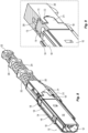
- the boot 112 with the center portion 200 and the front extension 110 are put onto the optical fibers/fiber optic cable as illustrated in Fig 6 .
- the optical fibers/fiber optic cable pass through the first longitudinal opening 208 and the second longitudinal opening 240 of the boot 112 and are secured in the fiber optic ferrules 104.
- the jacket or covering on the optical fibers/fiber optic cable is then secured to the crimp body 106 with a crimp ring and heat shrink tube 108 or in any other manner that is appropriate.
- the boot 112 is disposed on the optical fibers/fiber optic cable and the fiber optic connector has been assembled. As the boot 112 is moved to the fiber optic connector (to the left in FIG. 6 ), it is apparent that the front extension 110 will engage the rail receiving portion 158 of the crimp body 106 first and then the rail receiving portion 134 of the housing 102.
- FIG. 14 also illustrates (with the connector housing 102 removed for clarity) how the crimp body 106 engages the boot 112 and the latches 220 moving past the forward facing surfaces 176.
- the cut-outs 212 receive the portion 214 of the crimp body 106.
- the projections or latches 220 are disposed within the two notches 172 and are at the front end of the notches 172.
- the fiber optic connector 100 is as illustrated in FIGS. 1-5 and ready to be inserted into a receptacle. The user could push on the ribbed back portion 202, the grasping portions 238, the front extension 110, or the center portion 200 to insert the fiber optic connector 100 into the receptacle.
- the user could pull on the ribbed back portion 202, the grasping portions 238, the front extension 110, or the center portion 200.
- the front extension 110, the center portion 200, and ribbed back portion 202 move relative to the crimp body 106 and the housing 102, the projections or latches 220 sliding rearwardly within the two notches 172.
- the frictional force between the boot and the connector housing and crimp body should be low. It is desirable to have clearance between the boot and the crimp band, crimp body, housing, and the cable.
- a boot material that has a low coefficient of friction, such as polypropylene.
- a elastomeric boot material is not preferred because the user could deform the internal surface of the boot and cause added friction due to squeezing or pinching the boot while pulling.
- a material with a Young's Modulus greater than 500 MPa or possibly greater than 1 GPa has been shown not deform easily. See the arrows in FIG. 15 .
- the latch body 118 (and the adapter latch 114 and carrier latch 116) also does not move because the connector latch 294 has engaged the stop surface 136 of the housing 102. As the front extension 110 moves rearwardly, the main body 250 slides relative to the latch body 118 (and housing 102), pushing the adapter latch 114 and carrier latch 116 downward out of the windows and disengaging them from their respective receptacle.
- the fiber optic connector 100 could be simply removed from the receptacle by pulling on the ribbed back portion 202, the grasping portions 238, the front extension 110, or the center portion 200.
- the engagement of the projections or latches 220 with the forward facing surfaces 176 prevents the boot 112 from being disengaged from the crimp body 106 and the housing 102.
- the user could push on the bridge portion 222, which allows the boot 112 to be disengaged from the crimp body 106 and the housing 102.
- the boot 112 could be rotated about the optical fibers/fiber optic cable and reattached on the opposite side, thereby changing the polarity of the fiber optic connector 100.
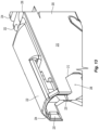
- FIGS. 16-18 illustrates another embodiment of a boot 500 for use with a fiber optic connector.
- the boot 500 has a front extension 502, a center portion 504, and a ribbed back portion 506.
- the front extension 502 of this embodiment is the same as that described above and will not be addressed any further.
- the ribbed back portion 506 functions in the same way as ribbed back portion 202 in that it can be used to push and pull on the fiber optic connector. It does have a different configuration with regard to the plurality of rib members 508 and the spine 510, but still provides sufficient strength to allow it to be used to install and remove the fiber optic connector while at the same time being flexible to provide strain relief to the optical fibers.
- the ribbed back portion 506 has only a single grasping portion 512 at the back end 514, although more grasping portions could be added.
- the spine 510 connects the plurality of rib members 508 from the center portion 504 to the grasping portion 512.
- the center portion 504 of the boot 500 is similar to the embodiment above, but with a few differences.
- the sides 516 that help to define the longitudinal opening therein do not have cut-outs.
- the sides of a crimp body 520 to be used with the boot 500 would not have to extend as far into the center portion with the engagement member noted below.
- the way of engagement between the center portion 504 and the crimp body 520 has changed. See FIG. 18 .
- the top and bottom of the center portion 500 have a single engagement member, a single element 522 that replaces the two projections or latches 220 in the prior embodiment.
- the single element 522 has a shape that is rounded at the front 524 and then has two rearward facing surfaces 526 to engage two inward facing latches 528, 530 in the crimp body 520.
- the interaction between the center portion 504 and the crimp body 520 is the same as discussed above.
- the boot 500 is advanced toward the crimp body 520 and the rounded front portion 524 causes the two inward facing latches 528, 530 in the crimp body 520 to spread apart, allowing the engagement member 522 to be disposed between them.
- the engagement member 522 moves relative to the two inward facing latches 528, 530. As discussed above, this movement causes the front extension 502 to release the latches and the engagement member 522 contacts the two inward facing latches 528, 530 to pull the fiber optic connector from the receptacle.
- the user can pull of the center portion 504 while holding the crimp body or housing and disengage the boot 500 from the crimp body with a little more force than was necessary to disengage the fiber optic connector from the receptacle.
- the rail receiving portion 540 has a central portion 542 and two lobe sections 544 to engage the front extension 502. However, the lobe sections 542 not as closed as the two lobe sections 162. This allows the rail receiving portion 540 to act more as an alignment feature allowing the front extension 502 to be aligned with and then inserted in to the rail receiving portion 540 from above it, rather than being inserted from the rear side as in the prior embodiment.
Landscapes
- Physics & Mathematics (AREA)
- General Physics & Mathematics (AREA)
- Optics & Photonics (AREA)
- Mechanical Coupling Of Light Guides (AREA)
Claims (5)
- Combinaison d'une tétine (112, 500) et d'un corps de sertissage (106, 520) pouvant être utilisée pour un connecteur de fibre optique comportant un boîtier (102), au moins deux ferrules de fibre optique (104) et un poussoir à ressort :
la tétine comprenant :une partie centrale (200, 504) ayant une extrémité avant (204, 502) et une extrémité arrière (206), une première ouverture longitudinale (208) s'étendant entre l'extrémité avant et l'extrémité arrière étant adaptée pour recevoir une partie du corps de sertissage et un câble de fibre optique ;une partie arrière (202, 506) reliée à la partie centrale et s'étendant à l'opposé de l'extrémité avant de la partie centrale, la partie arrière définissant une seconde ouverture longitudinale (240) qui est en communication avec la première ouverture longitudinale, la partie arrière ayant des parties de préhension (238) pour permettre à un utilisateur d'exercer une poussée et une traction sur la tétine ;la tétine comprenant en outreune partie d'extension avant (110) reliée à la partie centrale et pouvant être engagée avec le connecteur de fibre optique, la partie d'extension avant s'étendant vers l'avant et au-delà de l'extrémité avant de la partie centrale et comportant au moins un loquet (114, 116) destiné à s'engager dans une prise femelle ;le corps de sertissage comprenantune partie avant (150) configurée pour être disposée au moins partiellement dans le boîtier (102) ;une partie arrière (180) qui s'étend vers l'arrière à l'opposé de la partie avant et fournit une surface externe (182) pour recevoir une bande de sertissage autour d'elle ; etune partie centrale (152) disposée entre les parties avant et arrière,dans laquelle la tétine a un premier élément d'engagement (220, 522) destiné à coopérer avec un second élément d'engagement correspondant (172, 176) sur le corps de sertissage pour attacher de manière amovible la tétine au corps de sertissage, le second élément d'engagement étant disposé sur la partie centrale du corps de sertissage ; etdans laquelle le premier élément d'engagement (220) est dégagé du second élément d'engagement (172) lorsque la partie avant de la tétine (112) est pressée vers l'intérieur en direction de la première ouverture longitudinale (208). - Combinaison de la tétine et du corps de sertissage selon la revendication 1, dans laquelle le premier élément d'engagement comprend l'un d'au moins une saillie (220) et au moins une encoche et le second élément d'engagement comprend l'autre d'au moins une saillie et d'au moins un encoche (112), l'au moins une encoche ayant une longueur permettant un déplacement de l'au moins une saillie à l'intérieur de l'au moins une encoche sans se retrouver détachée.
- Combinaison de la tétine et du corps de sertissage selon la revendication 2, dans laquelle l'au moins une saillie comprend deux saillies et l'au moins une encoche (172) comprend deux encoches.
- Combinaison de la tétine et du corps de sertissage selon la revendication 2, dans laquelle l'au moins une encoche (172) comprend une surface orientée vers l'avant (176) et l'au moins une saillie (220) comprend une surface orientée vers l'arrière de telle sorte qu'une traction sur la tétine amène la surface orientée vers l'arrière à s'engager avec la surface orientée vers l'avant.
- Combinaison de la tétine et du corps de sertissage selon la revendication 1, dans laquelle une traction sur la tétine (112, 500) amène le premier élément d'engagement (220) à coulisser par rapport au second élément d'engagement (172), tirant ainsi l'extension avant vers l'arrière et libérant le connecteur de fibre optique (100) de la prise femelle.
Priority Applications (1)
| Application Number | Priority Date | Filing Date | Title |
|---|---|---|---|
| EP24216092.7A EP4492108A3 (fr) | 2018-04-06 | 2019-04-05 | Tétine de poussée-traction flexible et corps de sertissage pour connecteur de fibre optique |
Applications Claiming Priority (3)
| Application Number | Priority Date | Filing Date | Title |
|---|---|---|---|
| US201862653706P | 2018-04-06 | 2018-04-06 | |
| US201962793198P | 2019-01-16 | 2019-01-16 | |
| PCT/US2019/025944 WO2019195652A1 (fr) | 2018-04-06 | 2019-04-05 | Tétine de poussée-traction flexible et corps de sertissage pour connecteur de fibre optique |
Related Child Applications (2)
| Application Number | Title | Priority Date | Filing Date |
|---|---|---|---|
| EP24216092.7A Division EP4492108A3 (fr) | 2018-04-06 | 2019-04-05 | Tétine de poussée-traction flexible et corps de sertissage pour connecteur de fibre optique |
| EP24216092.7A Division-Into EP4492108A3 (fr) | 2018-04-06 | 2019-04-05 | Tétine de poussée-traction flexible et corps de sertissage pour connecteur de fibre optique |
Publications (3)
| Publication Number | Publication Date |
|---|---|
| EP3776033A1 EP3776033A1 (fr) | 2021-02-17 |
| EP3776033A4 EP3776033A4 (fr) | 2022-01-05 |
| EP3776033B1 true EP3776033B1 (fr) | 2025-02-26 |
Family
ID=68101153
Family Applications (2)
| Application Number | Title | Priority Date | Filing Date |
|---|---|---|---|
| EP24216092.7A Pending EP4492108A3 (fr) | 2018-04-06 | 2019-04-05 | Tétine de poussée-traction flexible et corps de sertissage pour connecteur de fibre optique |
| EP19782181.2A Active EP3776033B1 (fr) | 2018-04-06 | 2019-04-05 | Tétine de poussée-traction flexible et corps de sertissage pour connecteur de fibre optique |
Family Applications Before (1)
| Application Number | Title | Priority Date | Filing Date |
|---|---|---|---|
| EP24216092.7A Pending EP4492108A3 (fr) | 2018-04-06 | 2019-04-05 | Tétine de poussée-traction flexible et corps de sertissage pour connecteur de fibre optique |
Country Status (4)
| Country | Link |
|---|---|
| US (9) | US11719893B2 (fr) |
| EP (2) | EP4492108A3 (fr) |
| CN (2) | CN111971601B (fr) |
| WO (1) | WO2019195652A1 (fr) |
Families Citing this family (55)
| Publication number | Priority date | Publication date | Assignee | Title |
|---|---|---|---|---|
| US9658409B2 (en) | 2015-03-03 | 2017-05-23 | Senko Advanced Components, Inc. | Optical fiber connector with changeable polarity |
| US10158194B2 (en) | 2016-01-15 | 2018-12-18 | Senko Advanced Components, Inc. | Narrow width adapters and connectors with spring loaded remote release |
| US9726830B1 (en) | 2016-06-28 | 2017-08-08 | Senko Advanced Components, Inc. | Connector and adapter system for two-fiber mechanical transfer type ferrule |
| US10228521B2 (en) | 2016-12-05 | 2019-03-12 | Senko Advanced Components, Inc. | Narrow width adapters and connectors with modular latching arm |
| US11668890B2 (en) | 2017-06-28 | 2023-06-06 | Corning Research & Development Corporation | Multiports and other devices having optical connection ports with securing features and methods of making the same |
| WO2019005196A1 (fr) | 2017-06-28 | 2019-01-03 | Corning Research & Development Corporation | Connecteurs de fibres optiques compacts ayant de multiples empreintes de connecteur, conjointement avec des ensembles de câbles et leurs procédés de fabrication |
| US10359577B2 (en) | 2017-06-28 | 2019-07-23 | Corning Research & Development Corporation | Multiports and optical connectors with rotationally discrete locking and keying features |
| US11187859B2 (en) | 2017-06-28 | 2021-11-30 | Corning Research & Development Corporation | Fiber optic connectors and methods of making the same |
| US12271040B2 (en) | 2017-06-28 | 2025-04-08 | Corning Research & Development Corporation | Fiber optic extender ports, assemblies and methods of making the same |
| US11300746B2 (en) | 2017-06-28 | 2022-04-12 | Corning Research & Development Corporation | Fiber optic port module inserts, assemblies and methods of making the same |
| US12001064B2 (en) | 2017-07-14 | 2024-06-04 | Senko Advanced Components, Inc. | Small form factor fiber optic connector with multi-purpose boot |
| US10281669B2 (en) | 2017-07-14 | 2019-05-07 | Senko Advance Components, Inc. | Ultra-small form factor optical connectors |
| US11822133B2 (en) | 2017-07-14 | 2023-11-21 | Senko Advanced Components, Inc. | Ultra-small form factor optical connector and adapter |
| EP3682277B1 (fr) | 2017-09-15 | 2025-02-19 | Commscope Technologies LLC | Connecteur pour fibres optiques à libération intégrée à la tétine |
| CN115201974B (zh) | 2017-12-19 | 2024-04-30 | 美国康涅克有限公司 | 具有推拉极性机构和载体的微型双工连接器 |
| US11719893B2 (en) * | 2018-04-06 | 2023-08-08 | Us Conec Ltd. | Flexible push-pull boot and crimp body for fiber optic connector |
| EP3887883B1 (fr) | 2018-11-29 | 2023-11-08 | Corning Research & Development Corporation | Port multiple ayant des ports de connexion avec des actionneurs rotatifs |
| CA3125271C (fr) | 2018-12-28 | 2024-02-27 | Corning Research & Development Corporation | Ensembles multiport comprenant des elements de montage ou des bouchons anti-poussiere |
| US11971584B2 (en) | 2019-01-30 | 2024-04-30 | Us Conec Ltd. | Small form factor connector and adapter |
| US11579379B2 (en) | 2019-03-28 | 2023-02-14 | Senko Advanced Components, Inc. | Fiber optic adapter assembly |
| MX2021014427A (es) | 2019-05-31 | 2022-03-04 | Corning Res & Dev Corp | Multipuertos y otros dispositivos que tienen puertos de conexion optica con accionadores deslizantes y metodos para elaborar los mismos. |
| US11294133B2 (en) | 2019-07-31 | 2022-04-05 | Corning Research & Development Corporation | Fiber optic networks using multiports and cable assemblies with cable-to-connector orientation |
| US10845542B1 (en) | 2019-08-19 | 2020-11-24 | Afl Telecommunications Llc | Cable node transition assemblies |
| US10809480B1 (en) | 2019-09-30 | 2020-10-20 | Corning Research & Development Corporation | Dense wavelength division multiplexing fiber optic apparatuses and related equipment |
| US11487073B2 (en) | 2019-09-30 | 2022-11-01 | Corning Research & Development Corporation | Cable input devices having an integrated locking feature and assemblies using the cable input devices |
| EP3805827B1 (fr) | 2019-10-07 | 2025-07-30 | Corning Research & Development Corporation | Terminaux à fibres optiques et réseaux à fibres optiques ayant des coupleurs à rapport variable |
| PL4045957T3 (pl) | 2019-10-18 | 2024-04-29 | Corning Research & Development Corporation | Terminale mające optyczne porty połączeniowe z elementami mocującymi zapewniającymi stałe siły utrzymania |
| US11650388B2 (en) | 2019-11-14 | 2023-05-16 | Corning Research & Development Corporation | Fiber optic networks having a self-supporting optical terminal and methods of installing the optical terminal |
| JP7594008B2 (ja) * | 2019-11-20 | 2024-12-03 | センコー アドバンスド コンポーネンツ インコーポレイテッド | 可逆極性光ファイバコネクタ |
| US11474308B2 (en) * | 2019-12-18 | 2022-10-18 | Us Conec Ltd. | Flexible push-pull boot with a transition member |
| US11536921B2 (en) | 2020-02-11 | 2022-12-27 | Corning Research & Development Corporation | Fiber optic terminals having one or more loopback assemblies |
| EP4139725B1 (fr) | 2020-04-23 | 2025-04-02 | US Conec, Ltd | Ferrule multifibre miniature |
| US12321017B2 (en) | 2020-04-23 | 2025-06-03 | Us Conec Ltd. | Fiber optic ferrule and fiber optic ferrule receiver |
| US20230228949A1 (en) * | 2020-06-19 | 2023-07-20 | Us Conec Ltd. | System and method for guaranteeing correct polarity of fiber optic connector |
| EP4172671B1 (fr) | 2020-06-29 | 2026-01-21 | Corning Research & Development Corporation | Bornes ayant un orifice de connexion optique multifibre qui empêche un endommagement à partir de connecteurs à monofibre |
| TWM615335U (zh) * | 2020-09-23 | 2021-08-11 | 建毅科技股份有限公司 | 光纖連接器 |
| US11604320B2 (en) | 2020-09-30 | 2023-03-14 | Corning Research & Development Corporation | Connector assemblies for telecommunication enclosures |
| US11650379B2 (en) | 2020-10-14 | 2023-05-16 | Us Conec Ltd. | Anti-buckling latch for a fiber optic connector |
| CA3197081A1 (fr) | 2020-10-30 | 2022-05-05 | Stephen Paul CAPPANNARI | Connecteurs de fibres optiques a collier d'etancheite |
| US11927810B2 (en) | 2020-11-30 | 2024-03-12 | Corning Research & Development Corporation | Fiber optic adapter assemblies including a conversion housing and a release member |
| US11994722B2 (en) | 2020-11-30 | 2024-05-28 | Corning Research & Development Corporation | Fiber optic adapter assemblies including an adapter housing and a locking housing |
| US11880076B2 (en) | 2020-11-30 | 2024-01-23 | Corning Research & Development Corporation | Fiber optic adapter assemblies including a conversion housing and a release housing |
| US11686913B2 (en) | 2020-11-30 | 2023-06-27 | Corning Research & Development Corporation | Fiber optic cable assemblies and connector assemblies having a crimp ring and crimp body and methods of fabricating the same |
| US11982847B2 (en) * | 2020-12-18 | 2024-05-14 | Us Conec Ltd. | Flexible push-pull boot with a transition member |
| US12523821B2 (en) | 2021-04-08 | 2026-01-13 | Commscope Technologies Llc | Telecommunications connector with latch release mechanism |
| US11947167B2 (en) | 2021-05-26 | 2024-04-02 | Corning Research & Development Corporation | Fiber optic terminals and tools and methods for adjusting a split ratio of a fiber optic terminal |
| USD1030682S1 (en) * | 2021-07-26 | 2024-06-11 | US Conec, Ltd | Flexible dust plug for a small form factor multi-fiber connector |
| US12442984B2 (en) | 2021-10-04 | 2025-10-14 | Corning Research & Development Corporation | Integrated connector-wavelength division multiplexing device and fiber optic module including such devices |
| USD1031670S1 (en) | 2021-11-08 | 2024-06-18 | Us Conec Ltd. | Self-locking boot latch |
| US12422627B2 (en) * | 2022-05-02 | 2025-09-23 | Us Conec Ltd. | Data center interconnect for optical trunk cables having miniature multi-fiber ferrules |
| TWI810928B (zh) * | 2022-05-09 | 2023-08-01 | 立佳興業股份有限公司 | 光學連接器 |
| US12546954B2 (en) * | 2022-05-31 | 2026-02-10 | Us Conec Ltd. | Fiber cable jacket retention features for VSFF fiber-optic connectors |
| CN119790338A (zh) * | 2022-08-29 | 2025-04-08 | 康宁研究与开发公司 | 具有可旋转保护罩的光学连接器及相关方法 |
| CN120153300A (zh) * | 2022-10-28 | 2025-06-13 | 扇港元器件股份有限公司 | Mpo连接器及用于其的推拉护套 |
| WO2025057801A1 (fr) | 2023-09-12 | 2025-03-20 | 住友電工オプティフロンティア株式会社 | Connecteur optique |
Family Cites Families (58)
| Publication number | Priority date | Publication date | Assignee | Title |
|---|---|---|---|---|
| US4872736A (en) * | 1988-04-19 | 1989-10-10 | American Telephone And Telegraph Company, At&T Bell Laboratories | Connector assembly having a latching mechanism |
| US5425119A (en) * | 1993-09-23 | 1995-06-13 | Minnesota Mining And Manufacturing Company | Connector strain relief for optical fiber |
| US5737463A (en) | 1995-12-22 | 1998-04-07 | Weiss; Roger E. | Massive parallel optical interconnect system |
| US5619604A (en) | 1996-02-26 | 1997-04-08 | Alcoa Fujikura Limited | Multi-fiber optical connector |
| US6130977A (en) | 1998-07-17 | 2000-10-10 | Siecor Operations, Llc | Fiber optic connector sleeve having positioning ribs |
| US6149313A (en) | 1998-12-31 | 2000-11-21 | Siecor Operations, Llc | Gender selectable fiber optic connector and associated fabrication method |
| CA2288399A1 (fr) * | 1998-12-31 | 2000-06-30 | Markus A. Giebel | Connecteur de fibres optiques compatible mt rj dote d'une ferrule de forme cylindrique |
| JP3765525B2 (ja) | 1999-08-05 | 2006-04-12 | 矢崎総業株式会社 | 光コネクタ |
| US20020181893A1 (en) * | 2001-02-16 | 2002-12-05 | James White | Strain relief boot assembly for optical fibers |
| US7785019B2 (en) * | 2005-03-10 | 2010-08-31 | Corning Cable Systems Llc | Multi-fiber fiber optic receptacle and plug assembly |
| US7636507B2 (en) * | 2005-06-17 | 2009-12-22 | Adc Telecommunications, Inc. | Compact blind mateable optical splitter |
| US7775726B2 (en) * | 2007-02-16 | 2010-08-17 | 3M Innovative Properties Company | Remote grip optical fiber connector |
| JP5438754B2 (ja) * | 2008-04-25 | 2014-03-12 | スリーエム イノベイティブ プロパティズ カンパニー | スプライス要素を有する、現場終端処理可能lc形光コネクタ |
| US8152385B2 (en) * | 2009-02-27 | 2012-04-10 | Corning Cable Systems Llc | Duplex fiber optic assemblies suitable for polarity reversal and methods therefor |
| JP5439319B2 (ja) | 2010-09-06 | 2014-03-12 | 株式会社フジクラ | 光コネクタおよび光コネクタの挿抜方法 |
| EP2705395B1 (fr) | 2011-05-04 | 2020-01-08 | The Siemon Company | Connecteur de fibre optique à changement de polarité |
| US8764308B2 (en) * | 2011-06-06 | 2014-07-01 | Panduit Corp. | Duplex clip assembly for fiber optic connectors |
| US8556645B2 (en) * | 2012-01-23 | 2013-10-15 | Commscope, Inc. Of North Carolina | Delatching connector including extension member |
| CN102565963B (zh) * | 2012-02-27 | 2017-04-26 | 深圳日海通讯技术股份有限公司 | 一种高密度光纤连接器及其装配方法 |
| US9176285B2 (en) * | 2012-05-03 | 2015-11-03 | Adc Telecommunications, Inc. | Fiber optic connector |
| WO2014085462A1 (fr) * | 2012-11-30 | 2014-06-05 | Tyco Electronics Corporation | Connecteur à fibre optique avec boîtier extérieur de connecteur pouvant être installé sur place |
| JP6085471B2 (ja) * | 2012-12-21 | 2017-02-22 | 矢崎総業株式会社 | 光コネクタ |
| MX2016000475A (es) | 2013-07-16 | 2016-04-07 | 3M Innovative Properties Co | Conector para cubiertas de telecomunicaciones. |
| TWM466405U (zh) | 2013-07-23 | 2013-11-21 | Amphenol Fiber Optic Technology Shenzhen | 可適用不同類型帶有可移動聯結外殼的光纖連接器的插拔裝置 |
| US9207410B2 (en) | 2013-12-23 | 2015-12-08 | Alliance Fiber Optic Products, Inc. | Optical fiber connector assembly |
| CN109683248A (zh) * | 2014-09-26 | 2019-04-26 | 泰科电子(上海)有限公司 | 光纤连接器及其组装方法 |
| CN208953732U (zh) * | 2014-09-29 | 2019-06-07 | 康宁光电通信有限责任公司 | 用于多光纤光学连接器的套圈、光纤连接器和光纤电缆组件 |
| EP3201669A1 (fr) * | 2014-10-01 | 2017-08-09 | Corning Optical Communications LLC | Connecteur de fibres optiques avec ensemble d'élément de coulissement pour verrouillage à poussée-traction |
| US9983366B2 (en) * | 2014-11-04 | 2018-05-29 | 3M Innovative Properties Company | Field installed optical fiber connector for jacketed fiber cable and termination method |
| US9551842B2 (en) * | 2015-01-15 | 2017-01-24 | Corning Optical Communications LLC | Fiber optic connector with strain relief assembly |
| US9507101B2 (en) * | 2015-02-03 | 2016-11-29 | SENKO Advanced Components (HK) Ltd. | Optical fiber connector with improved optical fiber cable fixing mechanism |
| US9568689B2 (en) | 2015-02-18 | 2017-02-14 | US Conec, Ltd | Spring push and push-pull tab for tightly spaced fiber optic connectors |
| CN204595258U (zh) | 2015-04-20 | 2015-08-26 | 连展科技电子(昆山)有限公司 | 可快速解锁的光纤插头连接器 |
| US9739955B2 (en) | 2015-05-07 | 2017-08-22 | Alliance Fiber Optic Products, Inc. | Push-pull type fiber optic connector assembly |
| ES2908843T3 (es) | 2015-09-14 | 2022-05-04 | CommScope Connectivity Belgium BVBA | Carcasa de la férula con bota integrada |
| US9817195B2 (en) | 2015-10-13 | 2017-11-14 | 3M Innovative Properties Company | Cable sealing device |
| US9595786B1 (en) * | 2016-01-15 | 2017-03-14 | Senko Advanced Components, Inc. | Narrow width adapters and connectors with spring loaded remote release |
| US10191227B2 (en) * | 2016-01-20 | 2019-01-29 | Alliance Fiber Optics Products, Inc. | Fiber optic connector with small profile, and cable assemblies, systems, and methods including the same |
| EP3405824B1 (fr) * | 2016-01-20 | 2022-05-18 | Alliance Fiber Optic Products, Inc. | Connecteur de fibre optique à profil réduit, et des ensembles câbles et systèmes le comprenant |
| US9739954B1 (en) * | 2016-02-19 | 2017-08-22 | Corning Optical Communications LLC | Strain relief device for a fiber optic connector |
| CN109073838B (zh) * | 2016-03-10 | 2021-03-30 | 康宁光电通信有限责任公司 | 具有套圈缩回平衡的基于套圈的光纤连接器 |
| JP2017161832A (ja) | 2016-03-11 | 2017-09-14 | Seiオプティフロンティア株式会社 | 光コネクタ |
| TWM526695U (zh) | 2016-04-18 | 2016-08-01 | Gloriole Electroptic Technology Corp | 光纖連接器 |
| DE202016103178U1 (de) | 2016-06-16 | 2016-07-07 | Reichle & De-Massari Ag | Steckverbinder |
| JP6868989B2 (ja) * | 2016-09-20 | 2021-05-12 | 三和電気工業株式会社 | 光コネクタプラグの引抜タブ |
| DE102016117909A1 (de) | 2016-09-22 | 2018-03-22 | Reichle + De-Massari Ag | Steckverbinder und Verfahren zur Verriegelung und/oder Entriegelung eines Steckverbinders |
| WO2018140981A1 (fr) | 2017-01-30 | 2018-08-02 | Senko Advanced Components, Inc. | Connecteurs optiques à polarité réversible |
| MX2019013477A (es) * | 2017-05-11 | 2020-11-06 | Ppc Broadband Inc | Conector óptico empujable con articulación integrada por conector. |
| US10281669B2 (en) | 2017-07-14 | 2019-05-07 | Senko Advance Components, Inc. | Ultra-small form factor optical connectors |
| US10718911B2 (en) * | 2017-08-24 | 2020-07-21 | Senko Advanced Components, Inc. | Ultra-small form factor optical connectors using a push-pull boot receptacle release |
| JP6905434B2 (ja) | 2017-09-13 | 2021-07-21 | 三和電気工業株式会社 | 光コネクタ用タブ |
| EP3682277B1 (fr) | 2017-09-15 | 2025-02-19 | Commscope Technologies LLC | Connecteur pour fibres optiques à libération intégrée à la tétine |
| US10712512B2 (en) * | 2017-11-21 | 2020-07-14 | Senko Advanced Components, Inc | Fiber optic connector assemblies with cable boot release |
| CN115201974B (zh) | 2017-12-19 | 2024-04-30 | 美国康涅克有限公司 | 具有推拉极性机构和载体的微型双工连接器 |
| US10634854B2 (en) | 2018-01-03 | 2020-04-28 | Afl Ig Llc | Push-pull boot connector for fiber optic cables |
| WO2019191522A1 (fr) | 2018-03-28 | 2019-10-03 | Senko Advanced Components Inc | Connecteur de fibre optique à petit facteur de forme avec amorçage multifonctionnel |
| US11719893B2 (en) * | 2018-04-06 | 2023-08-08 | Us Conec Ltd. | Flexible push-pull boot and crimp body for fiber optic connector |
| US11119284B2 (en) | 2018-08-31 | 2021-09-14 | Go!Foton Holdings, Inc. | Integrated connector cable |
-
2019
- 2019-04-05 US US17/045,068 patent/US11719893B2/en active Active
- 2019-04-05 WO PCT/US2019/025944 patent/WO2019195652A1/fr not_active Ceased
- 2019-04-05 EP EP24216092.7A patent/EP4492108A3/fr active Pending
- 2019-04-05 CN CN201980024568.8A patent/CN111971601B/zh active Active
- 2019-04-05 EP EP19782181.2A patent/EP3776033B1/fr active Active
- 2019-04-05 CN CN202311461148.0A patent/CN117434655B/zh active Active
-
2020
- 2020-01-16 US US16/744,645 patent/US11112567B2/en active Active
-
2021
- 2021-09-03 US US17/466,282 patent/US11592627B2/en active Active
-
2023
- 2023-02-27 US US18/175,455 patent/US12013580B2/en active Active
- 2023-07-12 US US18/221,331 patent/US11815724B1/en active Active
- 2023-07-12 US US18/351,399 patent/US11906794B2/en active Active
-
2024
- 2024-02-17 US US18/444,676 patent/US20240192452A1/en not_active Abandoned
- 2024-05-16 US US18/666,590 patent/US12399330B2/en active Active
-
2025
- 2025-07-22 US US19/277,008 patent/US20250347859A1/en active Pending
Also Published As
| Publication number | Publication date |
|---|---|
| CN117434655A (zh) | 2024-01-23 |
| CN111971601B (zh) | 2023-11-21 |
| CN117434655B (zh) | 2025-09-09 |
| EP3776033A4 (fr) | 2022-01-05 |
| US20240192452A1 (en) | 2024-06-13 |
| US11112567B2 (en) | 2021-09-07 |
| US20250347859A1 (en) | 2025-11-13 |
| US20230358972A1 (en) | 2023-11-09 |
| US20230213709A1 (en) | 2023-07-06 |
| US11815724B1 (en) | 2023-11-14 |
| US12013580B2 (en) | 2024-06-18 |
| US12399330B2 (en) | 2025-08-26 |
| US20210405302A1 (en) | 2021-12-30 |
| US20230358973A1 (en) | 2023-11-09 |
| WO2019195652A1 (fr) | 2019-10-10 |
| EP3776033A1 (fr) | 2021-02-17 |
| EP4492108A2 (fr) | 2025-01-15 |
| US11592627B2 (en) | 2023-02-28 |
| US11719893B2 (en) | 2023-08-08 |
| EP4492108A3 (fr) | 2025-04-09 |
| US20200150357A1 (en) | 2020-05-14 |
| CN111971601A (zh) | 2020-11-20 |
| US20240302603A1 (en) | 2024-09-12 |
| US11906794B2 (en) | 2024-02-20 |
| US20210149124A1 (en) | 2021-05-20 |
Similar Documents
| Publication | Publication Date | Title |
|---|---|---|
| US11815724B1 (en) | Flexible push-pull boot and crimp body for fiber optic connector | |
| US11525965B2 (en) | Mini duplex connector with push-pull polarity mechanism and carrier with latch and rail | |
| KR102427148B1 (ko) | 모듈형 래칭 아암을 갖는 좁은 폭 어댑터 및 커넥터 | |
| US6565262B2 (en) | Trigger mechanism, optical cable connector including same, and method of assembling an optical cable connector | |
| CN109752803A (zh) | 多光纤推进式光纤连接器 | |
| US12601879B2 (en) | Flexible push-pull boot with a transition member | |
| JP2018049045A (ja) | 光コネクタプラグの引抜タブ | |
| US11982847B2 (en) | Flexible push-pull boot with a transition member | |
| CN114830002A (zh) | 针对多纤式插头壳体的多端口单尾套型连接器 | |
| CN110031939B (zh) | 具有模块化闩锁臂的窄宽度适配器和连接器 | |
| US20240337794A1 (en) | Boot Release/Lock Simplex And Duplex Optical Connectors |
Legal Events
| Date | Code | Title | Description |
|---|---|---|---|
| STAA | Information on the status of an ep patent application or granted ep patent |
Free format text: STATUS: THE INTERNATIONAL PUBLICATION HAS BEEN MADE |
|
| PUAI | Public reference made under article 153(3) epc to a published international application that has entered the european phase |
Free format text: ORIGINAL CODE: 0009012 |
|
| STAA | Information on the status of an ep patent application or granted ep patent |
Free format text: STATUS: REQUEST FOR EXAMINATION WAS MADE |
|
| 17P | Request for examination filed |
Effective date: 20200909 |
|
| AK | Designated contracting states |
Kind code of ref document: A1 Designated state(s): AL AT BE BG CH CY CZ DE DK EE ES FI FR GB GR HR HU IE IS IT LI LT LU LV MC MK MT NL NO PL PT RO RS SE SI SK SM TR |
|
| AX | Request for extension of the european patent |
Extension state: BA ME |
|
| DAV | Request for validation of the european patent (deleted) | ||
| DAX | Request for extension of the european patent (deleted) | ||
| A4 | Supplementary search report drawn up and despatched |
Effective date: 20211202 |
|
| RIC1 | Information provided on ipc code assigned before grant |
Ipc: G02B 6/38 20060101ALI20211126BHEP Ipc: G02B 6/36 20060101AFI20211126BHEP |
|
| STAA | Information on the status of an ep patent application or granted ep patent |
Free format text: STATUS: EXAMINATION IS IN PROGRESS |
|
| 17Q | First examination report despatched |
Effective date: 20230613 |
|
| P01 | Opt-out of the competence of the unified patent court (upc) registered |
Free format text: CASE NUMBER: APP_37144/2024 Effective date: 20240621 |
|
| GRAP | Despatch of communication of intention to grant a patent |
Free format text: ORIGINAL CODE: EPIDOSNIGR1 |
|
| STAA | Information on the status of an ep patent application or granted ep patent |
Free format text: STATUS: GRANT OF PATENT IS INTENDED |
|
| INTG | Intention to grant announced |
Effective date: 20240923 |
|
| GRAS | Grant fee paid |
Free format text: ORIGINAL CODE: EPIDOSNIGR3 |
|
| GRAA | (expected) grant |
Free format text: ORIGINAL CODE: 0009210 |
|
| STAA | Information on the status of an ep patent application or granted ep patent |
Free format text: STATUS: THE PATENT HAS BEEN GRANTED |
|
| AK | Designated contracting states |
Kind code of ref document: B1 Designated state(s): AL AT BE BG CH CY CZ DE DK EE ES FI FR GB GR HR HU IE IS IT LI LT LU LV MC MK MT NL NO PL PT RO RS SE SI SK SM TR |
|
| REG | Reference to a national code |
Ref country code: GB Ref legal event code: FG4D |
|
| REG | Reference to a national code |
Ref country code: CH Ref legal event code: EP |
|
| REG | Reference to a national code |
Ref country code: DE Ref legal event code: R096 Ref document number: 602019066534 Country of ref document: DE |
|
| REG | Reference to a national code |
Ref country code: IE Ref legal event code: FG4D |
|
| PGFP | Annual fee paid to national office [announced via postgrant information from national office to epo] |
Ref country code: NL Payment date: 20250427 Year of fee payment: 7 |
|
| REG | Reference to a national code |
Ref country code: SE Ref legal event code: TRGR |
|
| REG | Reference to a national code |
Ref country code: NL Ref legal event code: FP |
|
| PG25 | Lapsed in a contracting state [announced via postgrant information from national office to epo] |
Ref country code: RS Free format text: LAPSE BECAUSE OF FAILURE TO SUBMIT A TRANSLATION OF THE DESCRIPTION OR TO PAY THE FEE WITHIN THE PRESCRIBED TIME-LIMIT Effective date: 20250526 |
|
| PG25 | Lapsed in a contracting state [announced via postgrant information from national office to epo] |
Ref country code: FI Free format text: LAPSE BECAUSE OF FAILURE TO SUBMIT A TRANSLATION OF THE DESCRIPTION OR TO PAY THE FEE WITHIN THE PRESCRIBED TIME-LIMIT Effective date: 20250226 |
|
| PG25 | Lapsed in a contracting state [announced via postgrant information from national office to epo] |
Ref country code: PL Free format text: LAPSE BECAUSE OF FAILURE TO SUBMIT A TRANSLATION OF THE DESCRIPTION OR TO PAY THE FEE WITHIN THE PRESCRIBED TIME-LIMIT Effective date: 20250226 |
|
| PGFP | Annual fee paid to national office [announced via postgrant information from national office to epo] |
Ref country code: DE Payment date: 20250429 Year of fee payment: 7 |
|
| PG25 | Lapsed in a contracting state [announced via postgrant information from national office to epo] |
Ref country code: ES Free format text: LAPSE BECAUSE OF FAILURE TO SUBMIT A TRANSLATION OF THE DESCRIPTION OR TO PAY THE FEE WITHIN THE PRESCRIBED TIME-LIMIT Effective date: 20250226 |
|
| PGFP | Annual fee paid to national office [announced via postgrant information from national office to epo] |
Ref country code: GB Payment date: 20250428 Year of fee payment: 7 |
|
| REG | Reference to a national code |
Ref country code: LT Ref legal event code: MG9D |
|
| PG25 | Lapsed in a contracting state [announced via postgrant information from national office to epo] |
Ref country code: IS Free format text: LAPSE BECAUSE OF FAILURE TO SUBMIT A TRANSLATION OF THE DESCRIPTION OR TO PAY THE FEE WITHIN THE PRESCRIBED TIME-LIMIT Effective date: 20250626 Ref country code: NO Free format text: LAPSE BECAUSE OF FAILURE TO SUBMIT A TRANSLATION OF THE DESCRIPTION OR TO PAY THE FEE WITHIN THE PRESCRIBED TIME-LIMIT Effective date: 20250526 |
|
| PG25 | Lapsed in a contracting state [announced via postgrant information from national office to epo] |
Ref country code: HR Free format text: LAPSE BECAUSE OF FAILURE TO SUBMIT A TRANSLATION OF THE DESCRIPTION OR TO PAY THE FEE WITHIN THE PRESCRIBED TIME-LIMIT Effective date: 20250226 |
|
| PG25 | Lapsed in a contracting state [announced via postgrant information from national office to epo] |
Ref country code: PT Free format text: LAPSE BECAUSE OF FAILURE TO SUBMIT A TRANSLATION OF THE DESCRIPTION OR TO PAY THE FEE WITHIN THE PRESCRIBED TIME-LIMIT Effective date: 20250626 Ref country code: LV Free format text: LAPSE BECAUSE OF FAILURE TO SUBMIT A TRANSLATION OF THE DESCRIPTION OR TO PAY THE FEE WITHIN THE PRESCRIBED TIME-LIMIT Effective date: 20250226 |
|
| PGFP | Annual fee paid to national office [announced via postgrant information from national office to epo] |
Ref country code: FR Payment date: 20250425 Year of fee payment: 7 |
|
| PG25 | Lapsed in a contracting state [announced via postgrant information from national office to epo] |
Ref country code: GR Free format text: LAPSE BECAUSE OF FAILURE TO SUBMIT A TRANSLATION OF THE DESCRIPTION OR TO PAY THE FEE WITHIN THE PRESCRIBED TIME-LIMIT Effective date: 20250527 Ref country code: BG Free format text: LAPSE BECAUSE OF FAILURE TO SUBMIT A TRANSLATION OF THE DESCRIPTION OR TO PAY THE FEE WITHIN THE PRESCRIBED TIME-LIMIT Effective date: 20250226 |
|
| PGFP | Annual fee paid to national office [announced via postgrant information from national office to epo] |
Ref country code: CH Payment date: 20250501 Year of fee payment: 7 |
|
| PGFP | Annual fee paid to national office [announced via postgrant information from national office to epo] |
Ref country code: SE Payment date: 20250507 Year of fee payment: 7 |
|
| REG | Reference to a national code |
Ref country code: AT Ref legal event code: MK05 Ref document number: 1771179 Country of ref document: AT Kind code of ref document: T Effective date: 20250226 |
|
| PG25 | Lapsed in a contracting state [announced via postgrant information from national office to epo] |
Ref country code: SM Free format text: LAPSE BECAUSE OF FAILURE TO SUBMIT A TRANSLATION OF THE DESCRIPTION OR TO PAY THE FEE WITHIN THE PRESCRIBED TIME-LIMIT Effective date: 20250226 |
|
| PG25 | Lapsed in a contracting state [announced via postgrant information from national office to epo] |
Ref country code: DK Free format text: LAPSE BECAUSE OF FAILURE TO SUBMIT A TRANSLATION OF THE DESCRIPTION OR TO PAY THE FEE WITHIN THE PRESCRIBED TIME-LIMIT Effective date: 20250226 |
|
| PG25 | Lapsed in a contracting state [announced via postgrant information from national office to epo] |
Ref country code: IT Free format text: LAPSE BECAUSE OF FAILURE TO SUBMIT A TRANSLATION OF THE DESCRIPTION OR TO PAY THE FEE WITHIN THE PRESCRIBED TIME-LIMIT Effective date: 20250226 |
|
| PG25 | Lapsed in a contracting state [announced via postgrant information from national office to epo] |
Ref country code: AT Free format text: LAPSE BECAUSE OF FAILURE TO SUBMIT A TRANSLATION OF THE DESCRIPTION OR TO PAY THE FEE WITHIN THE PRESCRIBED TIME-LIMIT Effective date: 20250226 |
|
| PG25 | Lapsed in a contracting state [announced via postgrant information from national office to epo] |
Ref country code: EE Free format text: LAPSE BECAUSE OF FAILURE TO SUBMIT A TRANSLATION OF THE DESCRIPTION OR TO PAY THE FEE WITHIN THE PRESCRIBED TIME-LIMIT Effective date: 20250226 Ref country code: CZ Free format text: LAPSE BECAUSE OF FAILURE TO SUBMIT A TRANSLATION OF THE DESCRIPTION OR TO PAY THE FEE WITHIN THE PRESCRIBED TIME-LIMIT Effective date: 20250226 |
|
| PG25 | Lapsed in a contracting state [announced via postgrant information from national office to epo] |
Ref country code: RO Free format text: LAPSE BECAUSE OF FAILURE TO SUBMIT A TRANSLATION OF THE DESCRIPTION OR TO PAY THE FEE WITHIN THE PRESCRIBED TIME-LIMIT Effective date: 20250226 |
|
| PG25 | Lapsed in a contracting state [announced via postgrant information from national office to epo] |
Ref country code: SK Free format text: LAPSE BECAUSE OF FAILURE TO SUBMIT A TRANSLATION OF THE DESCRIPTION OR TO PAY THE FEE WITHIN THE PRESCRIBED TIME-LIMIT Effective date: 20250226 |
|
| REG | Reference to a national code |
Ref country code: DE Ref legal event code: R097 Ref document number: 602019066534 Country of ref document: DE |
|
| PG25 | Lapsed in a contracting state [announced via postgrant information from national office to epo] |
Ref country code: LU Free format text: LAPSE BECAUSE OF NON-PAYMENT OF DUE FEES Effective date: 20250405 |
|
| PG25 | Lapsed in a contracting state [announced via postgrant information from national office to epo] |
Ref country code: MC Free format text: LAPSE BECAUSE OF FAILURE TO SUBMIT A TRANSLATION OF THE DESCRIPTION OR TO PAY THE FEE WITHIN THE PRESCRIBED TIME-LIMIT Effective date: 20250226 |
|
| REG | Reference to a national code |
Ref country code: BE Ref legal event code: MM Effective date: 20250430 |
|
| PLBE | No opposition filed within time limit |
Free format text: ORIGINAL CODE: 0009261 |
|
| STAA | Information on the status of an ep patent application or granted ep patent |
Free format text: STATUS: NO OPPOSITION FILED WITHIN TIME LIMIT |
|
| REG | Reference to a national code |
Ref country code: CH Ref legal event code: L10 Free format text: ST27 STATUS EVENT CODE: U-0-0-L10-L00 (AS PROVIDED BY THE NATIONAL OFFICE) Effective date: 20260107 |
|
| PG25 | Lapsed in a contracting state [announced via postgrant information from national office to epo] |
Ref country code: BE Free format text: LAPSE BECAUSE OF NON-PAYMENT OF DUE FEES Effective date: 20250430 |
|
| 26N | No opposition filed |
Effective date: 20251127 |
|
| PG25 | Lapsed in a contracting state [announced via postgrant information from national office to epo] |
Ref country code: IE Free format text: LAPSE BECAUSE OF NON-PAYMENT OF DUE FEES Effective date: 20250405 |