EP3777516A1 - System zur messung der fotosyntheserate - Google Patents
System zur messung der fotosyntheserate Download PDFInfo
- Publication number
- EP3777516A1 EP3777516A1 EP19778024.0A EP19778024A EP3777516A1 EP 3777516 A1 EP3777516 A1 EP 3777516A1 EP 19778024 A EP19778024 A EP 19778024A EP 3777516 A1 EP3777516 A1 EP 3777516A1
- Authority
- EP
- European Patent Office
- Prior art keywords
- sensor
- air
- carbon dioxide
- covering
- lid
- Prior art date
- Legal status (The legal status is an assumption and is not a legal conclusion. Google has not performed a legal analysis and makes no representation as to the accuracy of the status listed.)
- Pending
Links
- 230000029553 photosynthesis Effects 0.000 title claims abstract description 24
- 238000010672 photosynthesis Methods 0.000 title claims abstract description 24
- 238000005259 measurement Methods 0.000 title claims abstract description 10
- CURLTUGMZLYLDI-UHFFFAOYSA-N Carbon dioxide Chemical compound O=C=O CURLTUGMZLYLDI-UHFFFAOYSA-N 0.000 claims abstract description 134
- 229910002092 carbon dioxide Inorganic materials 0.000 claims abstract description 67
- 239000001569 carbon dioxide Substances 0.000 claims abstract description 67
- 238000003756 stirring Methods 0.000 claims abstract description 35
- 230000004044 response Effects 0.000 claims abstract description 15
- 238000003780 insertion Methods 0.000 claims description 19
- 230000037431 insertion Effects 0.000 claims description 19
- 238000009423 ventilation Methods 0.000 claims description 11
- XLYOFNOQVPJJNP-UHFFFAOYSA-N water Chemical compound O XLYOFNOQVPJJNP-UHFFFAOYSA-N 0.000 description 5
- 238000002474 experimental method Methods 0.000 description 2
- 239000000463 material Substances 0.000 description 2
- 239000011490 mineral wool Substances 0.000 description 2
- 230000004043 responsiveness Effects 0.000 description 2
- 239000004925 Acrylic resin Substances 0.000 description 1
- 229920000178 Acrylic resin Polymers 0.000 description 1
- 230000007613 environmental effect Effects 0.000 description 1
- 238000011156 evaluation Methods 0.000 description 1
- 230000010365 information processing Effects 0.000 description 1
- 238000000034 method Methods 0.000 description 1
- 230000000243 photosynthetic effect Effects 0.000 description 1
- 239000002689 soil Substances 0.000 description 1
- 230000007704 transition Effects 0.000 description 1
- 239000012780 transparent material Substances 0.000 description 1
- 230000005068 transpiration Effects 0.000 description 1
Images


Classifications
-
- A—HUMAN NECESSITIES
- A01—AGRICULTURE; FORESTRY; ANIMAL HUSBANDRY; HUNTING; TRAPPING; FISHING
- A01G—HORTICULTURE; CULTIVATION OF VEGETABLES, FLOWERS, RICE, FRUIT, VINES, HOPS OR SEAWEED; FORESTRY; WATERING
- A01G7/00—Botany in general
-
- G—PHYSICS
- G01—MEASURING; TESTING
- G01N—INVESTIGATING OR ANALYSING MATERIALS BY DETERMINING THEIR CHEMICAL OR PHYSICAL PROPERTIES
- G01N21/00—Investigating or analysing materials by the use of optical means, i.e. using sub-millimetre waves, infrared, visible or ultraviolet light
- G01N21/17—Systems in which incident light is modified in accordance with the properties of the material investigated
- G01N21/25—Colour; Spectral properties, i.e. comparison of effect of material on the light at two or more different wavelengths or wavelength bands
- G01N21/31—Investigating relative effect of material at wavelengths characteristic of specific elements or molecules, e.g. atomic absorption spectrometry
-
- G—PHYSICS
- G01—MEASURING; TESTING
- G01N—INVESTIGATING OR ANALYSING MATERIALS BY DETERMINING THEIR CHEMICAL OR PHYSICAL PROPERTIES
- G01N33/00—Investigating or analysing materials by specific methods not covered by groups G01N1/00 - G01N31/00
- G01N33/0098—Plants or trees
-
- Y—GENERAL TAGGING OF NEW TECHNOLOGICAL DEVELOPMENTS; GENERAL TAGGING OF CROSS-SECTIONAL TECHNOLOGIES SPANNING OVER SEVERAL SECTIONS OF THE IPC; TECHNICAL SUBJECTS COVERED BY FORMER USPC CROSS-REFERENCE ART COLLECTIONS [XRACs] AND DIGESTS
- Y02—TECHNOLOGIES OR APPLICATIONS FOR MITIGATION OR ADAPTATION AGAINST CLIMATE CHANGE
- Y02A—TECHNOLOGIES FOR ADAPTATION TO CLIMATE CHANGE
- Y02A40/00—Adaptation technologies in agriculture, forestry, livestock or agroalimentary production
- Y02A40/10—Adaptation technologies in agriculture, forestry, livestock or agroalimentary production in agriculture
- Y02A40/25—Greenhouse technology, e.g. cooling systems therefor
Definitions
- the present invention relates to a photosynthesis rate measurement system capable of measuring a photosynthesis rate of plants.
- a system for measuring a photosynthesis rate of a plant is known.
- Patent Literature 1 discloses an evaluation system capable of evaluating a photosynthetic sample accurately and more easily.
- Patent Literature 1 JP-A-2017-44531
- the present invention provides a photosynthesis rate measurement system capable of measuring a carbon dioxide concentration in order to calculate a photosynthesis rate of a plant with a simple configuration.
- the present invention provides a photosynthesis rate measurement system of a plant, comprising: a covering portion covering a target plant, a sensor housing, and a sensor in the sensor housing alternately measuring carbon dioxide concentrations inside and outside the covering portion, wherein an air stirring portion to enhance the mixing of the air in the sensor housing is equipped inside the sensor housing.
- a photosynthesis rate measurement system comprising the covering portion covering the target plant, the sensor housing, and the sensor alternately measuring carbon dioxide concentrations inside and outside the covering portion.
- the sensor is provided in the sensor housing.
- the air stirring portion stirring the air exposing the sensor is provided inside the sensor housing. The air stirring portion is provided, so that the air flow is stirred, and the contact between the sensor and the air is promoted. Consequently, the response speed of the sensor is improved.
- the sensor measures the difference in the carbon dioxide concentrations between inflow air and outflow air of the covering portion
- the air stirring portion is provided to improve response speed of the sensor due to changes in the carbon dioxide concentration in the air on an inflow side or an outflow side of the air into the covering portion.
- the air stirring portion is provided to face a surface where the sensor and the air are in contact with each other inside the sensor housing.
- the covering portion comprises a canopy and a covering sheet
- the canopy is arranged above the target plant
- the covering sheet is arranged to cover a side of the target plant
- the covering sheet is configured to comprise an overlapped part covered by a plurality of sheets.
- the system further comprises a lid and a string
- the canopy is provided with a hole
- the lid comprises an insertion portion through which the string can be inserted and a slit extending from an outer edge of the lid to the insertion portion, the lid is arranged such that the insertion portion overlaps the hole and arranged to cover the hole in a plan view, and the string is inserted through the hole via the insertion portion.
- the slit is configured such that slit's width increases toward the edge of the lid.
- a diameter r of the hole and a diameter R of the lid satisfy a relationship of 2 ⁇ R/r.
- the canopy is provided with a ventilation fan.
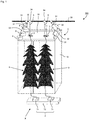
- a photosynthesis rate measurement system of a plant according to an embodiment of the present invention is described with reference to Fig. 1 to Fig. 7B .
- the photosynthesis rate measurement system is referred to as a system 100.
- the system 100 is configured to measure the carbon dioxide concentration around a plant 9 and to calculate a photosynthesis rate of the plant 9 from the carbon dioxide concentration.
- the photosynthesis rate of the plant 9 can be calculated in real time by means of the system 100 according to the present embodiment.
- the calculated result can be applied to environmental control for increasing the photosynthesis rate, for example, by adjusting the carbon dioxide concentration around the plant 9.
- the system 100 comprises a covering portion 1 covering the target plant 9, a sensor housing 5, and a sensor 4 configured to alternately measure the carbon dioxide concentration inside and outside the covering portion 1.
- the sensor 4 is provided in the sensor housing 5 in the present embodiment.
- the sensor 4 comprises a carbon dioxide sensor 41 and a water vapor sensor 42.
- the carbon dioxide sensor 41 is configured to measure the carbon dioxide concentration inside and outside the covering portion 1.
- the water vapor sensor 42 is configured to measure the water vapor concentration inside and outside the covering portion 1 in order to calculate a transpiration rate of the plant 9.
- an air stirring portion 51 for stirring flow of air flowing into the sensor housing 5 is provided inside the sensor housing 5.
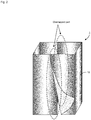
- the covering portion 1 comprises a canopy 10 and a covering sheet 12.
- the canopy 10 is arranged above the target plant 9, and the covering sheet 12 is arranged to cover the periphery of the target plant 9.
- the material of the canopy 10 is not particularly limited, though the material is preferably transparent.
- the canopy 10 can be formed of a transparent material, such as acrylic resin.
- the covering sheet 12 in the present embodiment is configured to comprise an overlapped part covered by a plurality of sheets.
- the covering sheet 12 is configured to have the overlapped part covered by the plurality of sheets, so that an operator can flip over the covering sheet 12 in the overlapped part and easily put his or her hand into the covering portion 1, thereby facilitating the care of the plant 9.
- the overlapped width of the overlapped part is not particularly limited, though the width is preferably 1 cm or more, and more preferably 3 cm or more.
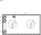
- the canopy 10 is provided with a hole 11, and a lid 2 comprises an insertion portion 21 through which a string 3 can be inserted and a slit 22 extending from an outer edge of the lid 2 to the insertion portion 21.
- the lid 2 is arranged, in a plan view, such that the insertion portion 21 overlaps the hole 11 and the lid 2 covers the hole 11.
- a wire 33 is arranged above the canopy 10. Further, the string 3 wound around a bobbin 34 attached to the wire 33 is inserted through the hole 11 of the canopy 10 via the insertion portion 21 provided on the lid 2 to hold the plant 9.
- the string 3 outside the bobbin 34 can be wound by the bobbin 34 to be shortened.
- the string 3 can be pulled out from the bobbin 34, so that the length of the string 3 outside the bobbin 34 can be increased.
- the canopy 10 is provided with the hole 11 in order to suspend the string 3 wound around the bobbin 34 into the covering portion 1.
- the lid 2 is provided to close the hole 11 in order to measure the carbon dioxide concentration inside the covering portion 1.
- the slit 22 in the present embodiment comprises a wide portion 23.
- the wide portion 23 is configured such that the width of the slit 22 increases toward the outer edge of the lid 2. Such a configuration facilitates the insertion of the string 3 from the wide portion 23 and the insertion of the string 3 through the insertion portion 21 by passing through the slit 22.
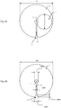
- the diameter r of the hole 11 and the diameter R of the lid 2 are preferably configured to satisfy the relationship of 2 ⁇ R/r.
- the hole 11 can be provided on the canopy 10, and the lid 2 can be arranged to cover the hole 11, so that the string 3 can be inserted through the insertion portion 21, thereby preventing the string 3 from coming off the hole 11.
- the hole 11 is always kept closed even when the lid 2 is moved.
- the value of R/r is, preferably, 2.1 to 3.0, and more preferably, 2.4 to 2.6.
- the value may be, for example, 2.1, 2.2, 2.3, 2.4, 2.5, 2.6, 2.7, 2.8, 2.9, 3.0, and the value may be within a range between any two of the values exemplified herein.
- the shape of the lid 2 is not particularly limited as long as the lid 2 can be arranged, in a plan view, such that the insertion portion 21 overlaps the hold 11 and the lid 2 covers the hole 11.
- the diameter R of the lid 2 can be set to be 220 mm
- the diameter of the insertion portion 21 can be set to be 10 mm
- the width of the slit 22 can be set to be 3 mm
- the width of the wide portion 23 at the outer edge of the lid 2 can be set to be 10 mm
- the length of the wide portion 23 can be set to be 5 mm.
- a plurality of length adjustment cords 31 attached to the wire 33 is attached to corners of the canopy 10.
- Each length adjustment cord 31 is provided with a length adjustment portion 32.
- the length of the length adjustment cord 31 can be adjusted by adjusting the length adjustment portion 32, so that the covering portion 1 can appropriately cover the plant 9 according to the height of the plan 9.
- the canopy 10 is provided with a ventilation fan 6.
- the ventilation fan 6 penetrates the canopy 10 and is configured to discharge air inside the covering portion 1 to the outside of the covering portion 1.
- a root holding portion 7 including roots of the plant 9 is provided below the covering sheet 12.
- the root holding portion 7 comprises rock wool 71 and a slab 72.
- the configuration of the root holding portion 7 is not particularly limited as long as the growth of the plant 9 can be maintained, and the root holding portion 7 may be configured as soil, reservoir or the like.
- the canopy 10 is provided with a pyranometer 8.
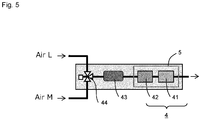
- the sensor 4 is described with reference to Fig. 5 , Fig. 6A and Fig. 6B .
- the sensor 4 is provided in the sensor housing 5 in the present embodiment.
- the sensor 4 comprises the carbon dioxide sensor 41 and the water vapor sensor 42.
- an air pump 43 and a three-way solenoid valve 44 for introducing air into the sensor housing 5 are provided.
- the three-way solenoid valve 44 is configured to switch the air introduced into the sensor housing 5 between air L or air M, and the air pump 43 is configured to introduce the air L or the air M to a side of the sensor 4.
- the air M represents air flowing into the covering portion 1 (air outside the covering portion 1).
- the air L represents air discharged to the outside of the covering portion 1.
- the carbon dioxide sensor 41 is configured to measure the difference in carbon dioxide concentration between an inflow side of air into the covering portion 1 and an outflow side of air from the covering portion 1.
- the carbon dioxide sensor 41 is configured to measure the difference in carbon dioxide concentration between the air flowing into the covering portion 1 and the air discharged to the outside of the covering portion 1. That is, the carbon dioxide sensor 41 is a sensor configured to detect the difference in carbon dioxide concentration.
- the configuration of the carbon dioxide sensor 41 is not limited to this, and a sensor directly detecting the carbon dioxide concentration may be used.
- the air stirring portion 51 is described with reference to Fig. 7A and Fig. 7B .
- the air stirring portion 51 for stirring flow of air flowing in the sensor housing 5 is provided inside the sensor housing 5.
- the shape of the air stirring portion 51 is not particularly limited, and the air stirring portion 51 configured as a plurality of protrusions is adopted in an example of Fig. 7B .
- the air stirring portion 51 in the present embodiment is provided inside the sensor housing 5 to face a surface (contact surface S) where the sensor 4 (carbon dioxide sensor 41) is in contact with air. With such configuration, the flow of air is disturbed, and the contact between the air and the sensor 4 (carbon dioxide sensor 41) can be promoted.
- the air stirring portion 51 contributes to improving the response speed of the sensor 4 (carbon dioxide sensor 41) due to change in carbon dioxide concentration when the air introduced into the sensor housing 5 is switched from the air flowing into the covering portion 1 to the air discharged from the covering portion 1 (or from the air discharged from the covering portion 1 to the air flowing into the covering portion 1).
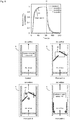
- the graph shown in Fig. 8 shows results of experiments conducted on the response speed of the sensor 4 (carbon dioxide sensor 41) for a reference (Control 1) and three comparison targets (flow paths A to C).
- the reference (Control 1) having no air stirring portion 51 on the surface (contact surface S) where the sensor 4 (carbon dioxide sensor 41) is in contact with air
- the flow path A and the flow path B provided with the air stirring portion 51 on the surface (contact surface S) where the sensor 4 (carbon dioxide sensor 41) is in contact with air
- the flow path C provided with the air stirring portion 51 in a position apart from the sensor 4 (carbon dioxide sensor 41) were prepared.
- FIG. 8 shows the normalized value of the carbon dioxide concentration output from the sensor 4 (carbon dioxide sensor 41) when the carbon dioxide concentration of the air introduced into the sensor housing 5 was changed from 380 ppm to 420 ppm.
- the carbon dioxide concentration of the air introduced into the sensor housing 5 was changed from 380 ppm to 420 ppm at time 0, and the carbon dioxide concentration of the air introduced into the sensor housing 5 was changed from 420 ppm to 380 ppm at time t1.
- the response time (from 0 to 90%) until the normalized carbon dioxide concentration reached 0.9 was 46 seconds.
- the response time (from 0 to 90%) was 37 seconds.
- the response time (from 0 to 90%) when the carbon dioxide concentration of the inflow air was changed from 420 ppm to 380 ppm was also the same.
- the results show that the responsiveness of the sensor 4 (carbon dioxide sensor 41) can be improved by providing the air stirring portion 51 on the surface (the contact surface S) where the sensor 4 (carbon dioxide sensor 41) is in contact with air.
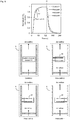
- the graph in Fig. 9 shows results of experiments conducted on the response speed of the sensor 4 (carbon dioxide sensor 41) for a reference (Control 2) and three comparison targets (flow paths D to F).
- the reference (Control 2) and the flow path D to the flow path F (corresponding to the air stirring portion 51) provided near the sensor 4 (carbon dioxide sensor 41) were prepared, and Fig. 9 shows the normalized value of the carbon dioxide concentration output from the sensor 4 (carbon dioxide sensor 41) when the carbon dioxide concentration of the air introduced into the sensor housing 5 was changed from 380 ppm to 420 ppm.
- Fig. 9 shows the normalized value of the carbon dioxide concentration output from the sensor 4 (carbon dioxide sensor 41) when the carbon dioxide concentration of the air introduced into the sensor housing 5 was changed from 380 ppm to 420 ppm.
- the carbon dioxide concentration of the air introduced into the sensor housing 5 was changed from 380 ppm to 420 ppm at time 0, and the carbon dioxide concentration of the air introduced into the sensor housing 5 was changed from 420 ppm to 380 ppm at time t1.
- a photosynthesis rate A can be calculated, for example, by the following equation.
- A F C in ⁇ C out
- the photosynthesis rate of the plant 9 can be calculated from the carbon dioxide concentration measured by the sensor 4 (carbon dioxide sensor 41).
- the system 100 of the present invention can also be implemented in the following aspects.
Landscapes
- Life Sciences & Earth Sciences (AREA)
- Physics & Mathematics (AREA)
- Spectroscopy & Molecular Physics (AREA)
- Biodiversity & Conservation Biology (AREA)
- Botany (AREA)
- Ecology (AREA)
- Forests & Forestry (AREA)
- Environmental Sciences (AREA)
- Health & Medical Sciences (AREA)
- Chemical & Material Sciences (AREA)
- Analytical Chemistry (AREA)
- Biochemistry (AREA)
- General Health & Medical Sciences (AREA)
- General Physics & Mathematics (AREA)
- Immunology (AREA)
- Pathology (AREA)
- Cultivation Of Plants (AREA)
- Greenhouses (AREA)
- Investigating Or Analysing Materials By Optical Means (AREA)
Applications Claiming Priority (2)
| Application Number | Priority Date | Filing Date | Title |
|---|---|---|---|
| JP2018062412A JP7181518B2 (ja) | 2018-03-28 | 2018-03-28 | 光合成速度計測システム |
| PCT/JP2019/012260 WO2019188848A1 (ja) | 2018-03-28 | 2019-03-22 | 光合成速度計測システム |
Publications (2)
| Publication Number | Publication Date |
|---|---|
| EP3777516A1 true EP3777516A1 (de) | 2021-02-17 |
| EP3777516A4 EP3777516A4 (de) | 2021-04-28 |
Family
ID=68061787
Family Applications (1)
| Application Number | Title | Priority Date | Filing Date |
|---|---|---|---|
| EP19778024.0A Pending EP3777516A4 (de) | 2018-03-28 | 2019-03-22 | System zur messung der fotosyntheserate |
Country Status (4)
| Country | Link |
|---|---|
| US (1) | US20210007288A1 (de) |
| EP (1) | EP3777516A4 (de) |
| JP (1) | JP7181518B2 (de) |
| WO (1) | WO2019188848A1 (de) |
Families Citing this family (6)
| Publication number | Priority date | Publication date | Assignee | Title |
|---|---|---|---|---|
| JP7525988B2 (ja) * | 2019-09-03 | 2024-07-31 | 株式会社スクウェア・エニックス | ビデオゲーム処理プログラム、及びビデオゲーム処理システム |
| JP7467887B2 (ja) | 2019-11-01 | 2024-04-16 | オムロン株式会社 | 植物生体センサ |
| JP7560114B2 (ja) * | 2021-02-10 | 2024-10-02 | 国立大学法人高知大学 | 光合成に関する学習データ作成装置、機械学習装置、推定装置、方法およびプログラム |
| CN113093620B (zh) * | 2021-04-07 | 2022-07-05 | 安徽农业大学 | 一种分布式光合速率监测系统 |
| CN112986246A (zh) * | 2021-04-26 | 2021-06-18 | 西南大学 | 自然光照植物群体气体交换检测箱及检测系统 |
| CN121038596A (zh) | 2023-01-31 | 2025-11-28 | 国立大学法人广岛大学 | 生物信息测定器和生物信息的测定方法 |
Family Cites Families (15)
| Publication number | Priority date | Publication date | Assignee | Title |
|---|---|---|---|---|
| JPS5751648Y2 (de) * | 1980-04-21 | 1982-11-10 | ||
| JPH07113775A (ja) * | 1993-10-18 | 1995-05-02 | Toyota Motor Corp | アルコール濃度検出装置 |
| JPH11125034A (ja) * | 1997-10-22 | 1999-05-11 | Katsuko Kawashima | 自立式簡易構築体 |
| DE60023005T2 (de) * | 1999-06-17 | 2006-07-20 | Smiths Detection Inc., Pasadena | Vielfach-sensor-system und -gerät |
| JP3968728B1 (ja) | 2006-04-03 | 2007-08-29 | 独立行政法人国際農林水産業研究センター | バッファーチャンバー方式ガス収支測定装置 |
| CA2828602A1 (en) * | 2010-03-16 | 2011-09-22 | Martin Mittelmark | Plant air purification enclosure apparatus and method |
| US20120181432A1 (en) * | 2011-01-13 | 2012-07-19 | Li-Cor, Inc. | Off-set compensation technique for dual analyzer gas exchange systems |
| US20140026474A1 (en) | 2012-07-25 | 2014-01-30 | Charles J. Kulas | Automated grow system |
| JP2014226064A (ja) | 2013-05-21 | 2014-12-08 | パイオニア株式会社 | 発光制御装置、発光制御方法、及びプログラム |
| US20150007498A1 (en) * | 2013-07-01 | 2015-01-08 | Joshua Hensley | Hydroponic system |
| US9678050B2 (en) * | 2014-07-30 | 2017-06-13 | Li-Cor, Inc. | Multi-functional piezo actuated flow controller |
| DE202015100160U1 (de) * | 2015-01-14 | 2016-04-15 | B+M Textil Gmbh & Co. Kg | Saat- und/oder Pflanzsystem |
| JP6599173B2 (ja) | 2015-08-25 | 2019-10-30 | 浜松ホトニクス株式会社 | 光合成サンプルの評価システム、光合成サンプルの評価方法、および光合成サンプルの評価プログラム |
| CA2981275C (en) * | 2016-10-26 | 2021-09-21 | Biochambers Incorporated | Whole plant gas exchange chamber using pressurization and ventilation of separated canopy and root zones |
| US10729080B2 (en) * | 2017-05-05 | 2020-08-04 | Benjamin Jon Staffeldt | Vertical aeroponic growing apparatus |
-
2018
- 2018-03-28 JP JP2018062412A patent/JP7181518B2/ja active Active
-
2019
- 2019-03-22 EP EP19778024.0A patent/EP3777516A4/de active Pending
- 2019-03-22 WO PCT/JP2019/012260 patent/WO2019188848A1/ja not_active Ceased
- 2019-03-22 US US17/041,154 patent/US20210007288A1/en not_active Abandoned
Also Published As
| Publication number | Publication date |
|---|---|
| JP7181518B2 (ja) | 2022-12-01 |
| US20210007288A1 (en) | 2021-01-14 |
| EP3777516A4 (de) | 2021-04-28 |
| WO2019188848A1 (ja) | 2019-10-03 |
| JP2019170247A (ja) | 2019-10-10 |
Similar Documents
| Publication | Publication Date | Title |
|---|---|---|
| EP3777516A1 (de) | System zur messung der fotosyntheserate | |
| JP5639701B1 (ja) | 水耕栽培装置及び水耕栽培方法 | |
| CN204612075U (zh) | 用于空气处理设备的可拆卸传感器模块 | |
| US8272259B2 (en) | Compact wind tunnel instrument | |
| KR200456891Y1 (ko) | 모형 비행기 날개 기류 흐름 관찰 장치 | |
| ATE511920T1 (de) | In sich geschlossener testsensor | |
| JP6516035B1 (ja) | 灌漑水量測定装置、灌漑水量測定方法、及びプログラム | |
| KR101773981B1 (ko) | 밀폐순환법 적용 챔버의 개폐감지 작동을 이용한 식물의 호흡과 광합성량 자동 모니터링 시스템 | |
| CN106153865A (zh) | 一种种植土壤参数检测装置 | |
| JP6970902B2 (ja) | 水耕栽培装置 | |
| JP4679103B2 (ja) | ガス検知装置 | |
| JP3559814B2 (ja) | 植物生育用容器 | |
| CN117030947A (zh) | 土壤呼吸监测装置 | |
| Palleja et al. | Electro-leaf, a biomimicry system to estimate in-canopy airflow in fruit crops | |
| US20180000022A1 (en) | Light traps and panels for light traps | |
| KR20220050627A (ko) | 카이툰을 이용한 미세먼지 플럭스 측정 장치 | |
| WO2004044618A2 (en) | Floating weather station | |
| JP2013231644A (ja) | 硝酸イオン濃度測定用センサおよび硝酸イオン濃度測定装置 | |
| EP4659564A1 (de) | Instrument zur messung biologischer informationen und verfahren zur messung biologischer informationen | |
| JP2016073263A (ja) | ハウス等の栽培作物への炭酸ガス施用設備と施用方法 | |
| KR102936941B1 (ko) | 대형 개방환경 가스 배출량 측정장치 | |
| EP4389231A1 (de) | Lüftersystem und verfahren zur bestimmung des maskentyps | |
| JP2014119357A (ja) | 油汚染土壌用定量測定システム | |
| CN206557191U (zh) | 一种植物毒性测定仪 | |
| Rai et al. | Design and development of an early warning system for potato disease-late blight |
Legal Events
| Date | Code | Title | Description |
|---|---|---|---|
| STAA | Information on the status of an ep patent application or granted ep patent |
Free format text: STATUS: THE INTERNATIONAL PUBLICATION HAS BEEN MADE |
|
| PUAI | Public reference made under article 153(3) epc to a published international application that has entered the european phase |
Free format text: ORIGINAL CODE: 0009012 |
|
| STAA | Information on the status of an ep patent application or granted ep patent |
Free format text: STATUS: REQUEST FOR EXAMINATION WAS MADE |
|
| 17P | Request for examination filed |
Effective date: 20201015 |
|
| AK | Designated contracting states |
Kind code of ref document: A1 Designated state(s): AL AT BE BG CH CY CZ DE DK EE ES FI FR GB GR HR HU IE IS IT LI LT LU LV MC MK MT NL NO PL PT RO RS SE SI SK SM TR |
|
| AX | Request for extension of the european patent |
Extension state: BA ME |
|
| A4 | Supplementary search report drawn up and despatched |
Effective date: 20210330 |
|
| RIC1 | Information provided on ipc code assigned before grant |
Ipc: A01G 7/00 20060101AFI20210324BHEP Ipc: G01N 21/31 20060101ALI20210324BHEP Ipc: G01N 33/00 20060101ALI20210324BHEP |
|
| DAV | Request for validation of the european patent (deleted) | ||
| DAX | Request for extension of the european patent (deleted) | ||
| STAA | Information on the status of an ep patent application or granted ep patent |
Free format text: STATUS: EXAMINATION IS IN PROGRESS |
|
| 17Q | First examination report despatched |
Effective date: 20230208 |