EP3777580B1 - Gebackene rauchvorrichtung - Google Patents
Gebackene rauchvorrichtung Download PDFInfo
- Publication number
- EP3777580B1 EP3777580B1 EP18920059.5A EP18920059A EP3777580B1 EP 3777580 B1 EP3777580 B1 EP 3777580B1 EP 18920059 A EP18920059 A EP 18920059A EP 3777580 B1 EP3777580 B1 EP 3777580B1
- Authority
- EP
- European Patent Office
- Prior art keywords
- heating assembly
- accommodating cavity
- smoking device
- sliding
- push tube
- Prior art date
- Legal status (The legal status is an assumption and is not a legal conclusion. Google has not performed a legal analysis and makes no representation as to the accuracy of the status listed.)
- Active
Links
Images



Classifications
-
- A—HUMAN NECESSITIES
- A24—TOBACCO; CIGARS; CIGARETTES; SIMULATED SMOKING DEVICES; SMOKERS' REQUISITES
- A24F—SMOKERS' REQUISITES; MATCH BOXES; SIMULATED SMOKING DEVICES
- A24F40/00—Electrically operated smoking devices; Component parts thereof; Manufacture thereof; Maintenance or testing thereof; Charging means specially adapted therefor
- A24F40/60—Devices with integrated user interfaces
-
- A—HUMAN NECESSITIES
- A24—TOBACCO; CIGARS; CIGARETTES; SIMULATED SMOKING DEVICES; SMOKERS' REQUISITES
- A24F—SMOKERS' REQUISITES; MATCH BOXES; SIMULATED SMOKING DEVICES
- A24F40/00—Electrically operated smoking devices; Component parts thereof; Manufacture thereof; Maintenance or testing thereof; Charging means specially adapted therefor
- A24F40/20—Devices using solid inhalable precursors
-
- A—HUMAN NECESSITIES
- A24—TOBACCO; CIGARS; CIGARETTES; SIMULATED SMOKING DEVICES; SMOKERS' REQUISITES
- A24F—SMOKERS' REQUISITES; MATCH BOXES; SIMULATED SMOKING DEVICES
- A24F40/00—Electrically operated smoking devices; Component parts thereof; Manufacture thereof; Maintenance or testing thereof; Charging means specially adapted therefor
- A24F40/40—Constructional details, e.g. connection of cartridges and battery parts
- A24F40/46—Shape or structure of electric heating means
Definitions
- the present invention relates to the field of cigarette substitutes, in particular to a baked smoking device.
- SHS secondhand smoke
- a typical low-temperature baked smoking device in the prior art includes a power supply and a heating assembly.
- the power supply and the heating assembly are integrally arranged and cannot be disassembled. As a result, the heating assembly cannot be replaced separately. Besides, it is not easy to clean the inside of the heating assembly.
- Publication CN 206 687 163 U discloses a low-temperature baking smoking set comprising a casing, a heating cup and a heating element.
- the heating cup comprises one end having an opening in which a cigarette can be inserted.
- the baking smoking set further comprises a sliding button for pushing the heating cup out of the casing.
- a technical problem to be solved by the present invention is to provide a baked smoking device.
- a technical solution of the present invention adopted for solving the technical problem is to provide a baked smoking device including a body, a heating assembly and a sliding button, wherein;
- the first stroke and the second stroke are two continuous strokes.
- the heating assembly includes a sleeve; an inner hole of the push tube is defined as the insertion hole for inserting the cigarette; the sleeve is sleeved outside the push tube; the sliding button abuts against the push tube; the sliding button is able to drive the push tube and the cigarette to move together in the first stroke from a first position adjacent to an inner end of the insertion hole to a second position adjacent to an outer end of the insertion hole.
- a reposition member is provided between the sleeve and the push tube to provide a force for resetting the push tube to the first position.
- the sleeve is provided with a first limiting portion for limiting the push tube when the push tube moves to the second position; and when the sliding button continues to move to a third position adjacent to the outside of the accommodating cavity, the first limiting portion is able to drive the heating assembly to move towards the outside of the accommodating cavity to complete the second stroke of the heating assembly.
- the push tube is provided with an abutting portion that extends laterally outwards; a side wall of the sleeve is axially provided with a sliding groove; the abutting portion is clamped into the sliding groove, and the sliding button abuts against the abutting portion.
- a side of the sliding groove adjacent to the outside of the accommodating cavity defines the first limiting portion.
- a second limiting portion is provided on the body, for limiting the sliding button when the sliding button drives the heating assembly to move towards the outside of the accommodating cavity to the third position.
- the heating assembly further includes a heating element extending from the bottom of the insertion hole to an outer end opening of the insertion hole.
- the heating assembly further includes a protective cover detachably sleeved on the heating element;
- the heating assembly further includes a heat insulation seat for mounting the heating element; a thermal conductivity of the heat insulation seat is lower than that of the heating element;
- a side wall of the body is provided with a mounting hole for the sliding button to slide back and forth;
- the sliding button includes an inner sliding member and an outer sliding member respectively located on inner and outer sides of the side wall of the body; the outer sliding member extends through the mounting hole to be clamped and fixed with the inner sliding member; a sliding rail for the sliding button to slide is provided inside the body.
- the body is provided with a locking structure for positioning and fixing the inserted heating assembly.
- the locking structure includes a lock head; the lock head retractably extends from a side wall surface of the accommodating cavity into the accommodating cavity; an outer wall surface of the heating assembly is provided with a lock groove for the lock head to be snapped into.
- an end of the lock head towards the accommodating cavity is tapered or round; a side wall surface of the lock groove is an inclined surface or an arc surface.
- the lock groove is circumferentially provided on an outer surface of the heating assembly.
- the baked smoking device of the present invention has the following beneficial effects:
- the sliding button is slided to different positions, to push out the cigarette and the heating assembly respectively. Therefore, the cigarette can be conveniently replaced, and the disassembly of the heating assembly and a power supply assembly such as a power source of the body can be conveniently implemented, which facilitates the replacement of the heating assembly and clean of the interior of the heating assembly.
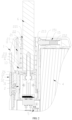
- a baked smoking device in a preferred embodiment of the present invention includes a body 1, a heating assembly 2, a sliding button 3, a power source 4 and a control board 5.
- the body 1 includes a casing.
- the body 1 is provided with an accommodating cavity 11, and the heating assembly 2 is inserted in the accommodating cavity 11.
- the heating assembly 2 is provided with an insertion hole 221 for inserting a cigarette 6.
- the sliding button 3 is mounted on the body 1 and mounted to the heating assembly 2.
- the sliding button 3 is cooperated with the heating assembly 2, and configured to slide along a first stroke to push the cigarette 6 in the heating assembly 2 out of the insertion hole 221 and to slide along a second stroke to push the heating assembly 2 out of the accommodating cavity 11.
- the sliding button 3 is slided to different positions, to push out the cigarette 6 and the heating assembly 2 respectively. Therefore, the cigarette 6 can be conveniently replaced, and the disassembly of the heating assembly 2 and a power supply assembly such as the power source 4 of the body 1 can be conveniently implemented, which facilitates the replacement of the heating assembly 2 and clean of the interior of the heating assembly 2.
- a side wall of the body 1 is provided with a mounting hole 12 for the sliding button 3 to slide back and forth.
- the sliding button 3 includes an inner sliding member 31 and an outer sliding member 32 respectively located on inner and outer sides of the side wall of the body 1.
- the outer sliding member 32 extends through the mounting hole 12 to be clamped and fixed with the inner sliding member 31.
- a sliding rail 13 for the sliding button 3 to slide is provided inside the body 1.
- the sliding button 3 may alternatively be an integrated structure that is able to slide on the body 1.
- the heating assembly 2 includes a sleeve 21, a push tube 22, a reposition member 23, a heating element 24, a protective cover 25, a clamping seat 26, a heat insulation seat 27, a support assembly 28 and a lock sleeve 29.
- An inner hole of the push tube 22 is defined as the insertion hole 221 for inserting the cigarette 6.
- the sleeve 21 is sleeved outside the push tube 22.
- the sliding button 3 abuts against the push tube 22, and the sliding button 3 is able to drive the push tube 22 and the cigarette 6 to move together in the first stroke from a first position A adjacent to an inner end of the insertion hole 221 to a second position B adjacent to an outer end of the insertion hole 221.
- the reposition member 23 is provided between the sleeve 21 and push tube 22 to provide a force for resetting the push tube 22 to the first position A.
- the reposition member 23 is a spring sleeved outside the push tube 22, and two ends of the spring respectively abut against the sleeve 21 and the push tube 22.
- the reposition member 23 can provide a force to the push tube 22 towards an inner end of the accommodating cavity 11.
- the push tube 22 may alternatively be pushed to the first position A manually.
- the first stroke and the second stroke are two continuous strokes. If only the cigarette 6 needs to be pushed out, the push tube 22 moves to the second position B. If the heating assembly 2 needs to be pushed out, the push tube 22 is continuously pushed outward from the second position B to the third position C, so that the heating assembly 2 moves towards the outside of the accommodating cavity 11. In this way, the heating assembly 2 can be removed for maintenance.
- the push tube 22 is provided with an abutting portion 222 that extends laterally outwards, and a side wall of the sleeve 21 is axially provided with a sliding groove 212.
- the abutting portion 222 is clamped into the sliding groove 212, and the abutting portion 222 is able to move in the sliding groove 212.
- the sliding button 3 abuts against the abutting portion 222, and applies a force to the abutting portion 222 to drive the push tube 22 to move towards the outside of the accommodating cavity 11.
- the sliding button 3 may alternatively abut against a structure such as a positioning hole on an end or a side wall of the push tube 22, to force the push tube 22 to move outward.
- a second limiting portion 14 is provided on the body 1 for limiting the sliding button 3 when the sliding button 3 drives the heating assembly 2 to move towards the outside of the accommodating cavity 11 to the third position C.
- a distance between the second position B and the third position C is not limited, as long as the heating assembly 2 is pushed outward for a certain distance so that a user can pull the heating assembly 2 out of the accommodating cavity 11.
- the sliding button 3 may alternatively rely on the mounting hole 12 to limit a moving range thereof. When the sliding button 3 moves to a boundary of a side of the mounting hole 12, the heating assembly 2 is just moved to the third position C.
- the heating element 24 is disposed on the heat insulation seat 27.
- the heating element 24 extends from the bottom of the insertion hole 221 to an outer end opening of the insertion hole 221.
- the protective cover 25 is detachably sleeved on the heating element 24. When the heating assembly 2 is removed from the accommodating cavity 11, the protective cover 25 can be removed for replacement or cleaning.
- a thermal conductivity of the heat insulation seat 27 is lower than that of the heating element 24, which can prevent the heat on the heating element 24 from being transferred to the support assembly 28, a circuit board and a guide, etc., so as to reduce the safety risk.
- An end of the protective cover 25 towards an outer end of the insertion hole 221 is a closed pointed structure.
- the closed pointed structure facilitates the insertion of the protective cover 25 into the cigarette 6, and also prevents chemicals generated when the cigarette 6 is heated from entering the protective cover 25.
- the heating element 24 has a cylindrical or sheet shape.
- An inner surface of the protective cover 25 may be closely fit with or spaced apart from the heating element 24, as long as the heat can be transferred to the protective cover 25 to heat the cigarette 6.
- the support assembly 28 includes a first clamping member 281, a second clamping member 282 and a support sleeve 283.
- the first clamping member 281 and the second clamping member 282 clamp the heat insulation seat 27.
- Two sides of the first clamping member 281 and the second clamping member 282 towards each other are respectively provided with a positioning groove 2811 for engaging the heat insulation seat 27, to facilitate positioning.
- the heating element 24 extends outward into the insertion hole 221 from the heat insulation seat 27.
- an abutting wall 223 is provided at the bottom of the insertion hole 221.
- the abutting wall 223 is able to abut and position an inner end of the cigarette 6, and the abutting wall 223 is provided with a through hole 224 for the heating element 24 to extend through.
- the abutting wall 223 and the push tube 22 are of an integrated structure, or alternatively be two separate components that are relatively fixed in position.
- the support sleeve 283 is sleeved outside the first clamping member 281 and the second clamping member 282.
- a positioning ring 2831 is provided on an inner periphery of one end of the support sleeve 283 adjacent to the insertion hole 221, for abutting the first clamping member 281 and the second clamping member 282 to limit axial positions thereof.
- the positioning ring 2831 may alternatively be located on an inner periphery of one end of the support sleeve 283 away from the insertion hole 221.
- one end of the sliding groove 212 away from the accommodating cavity 11 extends to an end of the sleeve 21.
- the support assembly 28 is mounted into the sleeve 21 via an end of the sleeve 21 where the sliding groove 212 is located.
- the abutting portion 222 is mounted into the sliding groove 212 via an open end of the sliding groove 212.
- the lock sleeve 29 is connected with the end of the sleeve 21 where the sliding groove 212 is located, to lock the support assembly 28 in the sleeve 21.
- the clamping seat 26 is located on a side of the through hole 224 opposite to the insertion hole 221, and the clamping seat 26 is configured to be clamped and fixed with the protective cover 25.
- the clamping seat 26 is annular and is sleeved on the heating element 24.
- an inner clamping groove 261 is provided on a side wall of an inner periphery of the clamping seat 26, and an outer periphery of an inner end of the protective cover 25 is provided with a retaining ring 251 that is clamped with the inner clamping groove 261.
- an outer periphery of the clamping seat 26 is provided with an outer clamping groove 262 that is clamped with the positioning ring 2831 of the support sleeve 283. In this way, both the inner and outer peripheries of the clamping seat 26 are positioned and fixed.
- the protective cover 25 may be clamped with only the inner or outer periphery of the clamping seat 26.
- the clamping seat 26 is made of a soft material, which is convenient for the protective cover 25 to squeeze the clamping seat 26 and snap into the inner clamping groove 261, and is also convenient for the clamping seat 26 to be disassembled. When the protective cover 25 is removed, the clamping seat 26 may also be removed simultaneously for cleaning.
- An outer size of the through hole 224 is smaller than a size of the inner periphery of the clamping seat 26, which facilitates the abutment of the clamping seat 26 and prevents the protective cover 25 from being pulled out of the through hole 224.
- an outer periphery of the retaining ring 251 is provided with a surrounding plate 252 extending in a direction of the outer end opening of the insertion hole 221.
- the surrounding plate 252 and the retaining ring 251 form a container outside the protective cover 25, which is used to contain an impurity falling from the protective cover 25 during use, so as to prevent contamination of other components.
- a gap is defined between an inner periphery of the through hole 224 and an outer wall surface of the protective cover 25, so that the impurity on the protective cover 25 is able to fall from between the through hole 224 and the protective cover 25 to the container formed by the surrounding plate 252 and the retaining ring 251.
- the body 1 is provided with a locking structure 15 for positioning and fixing the inserted heating assembly 2. As the heating assembly 2 is fixed in position, it will not shake and loosen during use.
- the locking structure 15 includes a lock head 151.
- the lock head 151 retractably extends from a side wall surface of the accommodating cavity 11 into the accommodating cavity 11.
- An outer wall surface of heating assembly 2 is provided with a lock groove 213 for the lock head 151 to be snapped into. When the lock head 151 is snapped into the lock groove 213, the heating assembly 2 is prevented from leaving the accommodating cavity 11.
- an end of the lock head 151 towards the accommodating cavity 11 is tapered or round, and a side wall surface of the lock groove 213 is an inclined surface or an arc surface, enabling the heating assembly 2 to overcome a locking force of the lock head 151 under the push by the sliding button 3 to let the lock head 151 be retracted, so that the heating assembly 2 is removed from the accommodating cavity 11.
- the lock head 151 may alternatively be retracted manually, so that the lock of the lock head 151 is released.
- the locking structure 15 further includes an elastic member 152 that provides an elastic force to keep the lock head 151 extending into the accommodating cavity 11.
- the elastic member 152 is a spring.
- the lock groove 213 is circumferentially provided on an outer surface of the sleeve 21, so that a circumferential position of the heating assembly 2 when mounting into the accommodating cavity 11 can be neglected.
Landscapes
- Engineering & Computer Science (AREA)
- Human Computer Interaction (AREA)
- Resistance Heating (AREA)
- Baking, Grill, Roasting (AREA)
Claims (13)
- Gebackene Rauchvorrichtung, umfassend einen Körper (1), eine Heizbaugruppe (2) und einen Schiebetaster (3), wobei;der Körper (1) mit einem Aufnahmehohlraum (11) bereitgestellt ist und die Heizbaugruppe (2) in dem Aufnahmehohlraum (11) angeordnet ist;die Heizbaugruppe (2) ein Schubrohr (22), das mit einem Einführloch (221) zum Einführen einer Zigarette (6) bereitgestellt ist, und ein Heizelement (24), das sich von einem Boden des Einführlochs (221) zu einer äußeren Endöffnung des Einführlochs (221) erstreckt, umfasst;der Schiebetaster (3) an dem Körper (1) angeordnet ist und mit der Heizbaugruppe (2) zusammenwirkt, dadurch gekennzeichnet, dass der Schiebetaster (3) konfiguriert ist, entlang eines ersten Hubs zu gleiten, um das Schubrohr (22) aus dem Einführloch (221) zu drücken, und entlang eines zweiten Hubs zu gleiten, um die gesamte Heizbaugruppe (2) aus dem Aufnahmehohlraum (11) zu schieben.
- Gebackene Rauchvorrichtung nach Anspruch 1, wobei der erste Hub und der zweite Hub zwei kontinuierliche Hübe sind.
- Gebackene Rauchvorrichtung nach Anspruch 1, wobei die Heizbaugruppe (2) eine Hülse (21) umfasst;
ein Innenloch des Schubrohres (22) als das Einführloch (221) zum Einführen der Zigarette (6) definiert ist; die Hülse (21) außerhalb des Schubrohres (22) ummantelt ist; der Schiebetaster (3) an dem Schubrohr (22) anliegt, und der Schiebetaster (3) in der Lage ist, das Schubrohr (22) und die Zigarette (6) im ersten Hub gemeinsam von einer ersten Position (A), benachbart zu einem inneren Ende des Einführlochs (221), zu einer zweiten Position (B), benachbart zu einem äußeren Ende des Einführlochs (221), zu bewegen. - Gebackene Rauchvorrichtung nach Anspruch 3, wobei ein Umpositionselement (23) zwischen der Hülse (21) und dem Schubrohr (22) bereitgestellt ist, um eine Kraft zum Zurücksetzen des Schubrohrs (22) in die erste Position (A) bereitzustellen.
- Gebackene Rauchvorrichtung nach Anspruch 3, wobei die Hülse (21) mit einem ersten Begrenzungsabschnitt (211) zum Begrenzen des Schubrohrs (22) bereitgestellt ist, wenn sich das Schubrohr (22) in die zweite Position (B) bewegt; und wenn sich der Schiebetaster (3) weiter in eine dritte Position (C) benachbart zu der Außenseite des Aufnahmehohlraums (11) bewegt, der erste Begrenzungsabschnitt (211) in der Lage ist, die Heizbaugruppe (2) antreiben, sich in Richtung der Außenseite des Aufnahmehohlraums (11) zu bewegen, um den zweiten Hub der Heizbaugruppe (2) zu vervollständigen.
- Gebackene Rauchvorrichtung nach Anspruch 5, wobei das Schubrohr (22) mit einem sich seitlich nach außen erstreckenden Anlageabschnitt (222) bereitgestellt ist, wobei eine Seitenwand der Hülse (21) axial mit einer Gleitnut (212) bereitgestellt ist;
der Anlageabschnitt (222) in die Gleitnut (212) eingespannt ist und der Schiebetaster (3) an dem Anlageabschnitt (222) anliegt. - Gebackene Rauchvorrichtung nach Anspruch 6, wobei eine Seite der Gleitnut (212) benachbart zu der Außenseite des Aufnahmehohlraums (11) den ersten Begrenzungsabschnitt (211) definiert.
- Gebackene Rauchvorrichtung nach Anspruch 5, wobei an dem Körper (1) ein zweiter Begrenzungsabschnitt (14) bereitgestellt ist, um den Schiebetaster (3) zu begrenzen, wenn der Schiebetaster (3) die Heizbaugruppe (2) antreibt, sich in Richtung der Außenseite des Aufnahmeraums (11) in die dritte Position (C) zu bewegen.
- Gebackene Rauchvorrichtung nach einem der Ansprüche 1 bis 8, wobei eine Seitenwand des Körpers (1) mit einem Befestigungsloch (12) zum Hin- und Hergleiten des Schiebetasters (3) bereitgestellt ist; der Schiebetaster (3) ein inneres Gleitelement (31) und ein äußeres Gleitelement (32) umfasst, die jeweils an den Innen- und Außenseiten der Seitenwand des Körpers (1) angeordnet sind; sich das äußere Gleitelement (32) durch das Befestigungsloch (12) erstreckt, um mit dem inneren Gleitelement (31) festgeklemmt und befestigt zu werden; eine Gleitschiene (13) für den Schiebetaster (3) innerhalb des Körpers (1) vorgesehen ist.
- Gebackene Rauchvorrichtung nach einem der Ansprüche 1 bis 8, wobei der Körper (1) mit einer Verriegelungsstruktur (15) zum Positionieren und Fixieren der eingesetzten Heizbaugruppe (2) bereitgestellt ist.
- Gebackene Rauchvorrichtung nach Anspruch 10, wobei die Verriegelungsstruktur (15) einen Verriegelungskopf (151) umfasst; sich der Verriegelungskopf (151) von einer Seitenwandfläche des Aufnahmehohlraums (11) in den Aufnahmehohlraum (11) zurückziehbar erstreckt; eine Außenwandfläche der Heizbaugruppe (2) mit einer Verriegelungsnut (213) zum Einschnappen des Verriegelungskopfes (151) bereitgestellt ist; ein Ende des Verriegelungskopfes (151) zum Aufnahmehohlraum (11) hin verjüngt oder rund ist; eine Seitenwandfläche der Verriegelungsnut (213) eine geneigte Fläche oder eine Bogenfläche ist.
- Gebackene Rauchvorrichtung nach Anspruch 11, wobei die Verriegelungsnut (213) umfangsmäßig an einer Außenfläche der Heizbaugruppe (2) bereitgestellt ist; die Verriegelungsstruktur (15) ferner ein elastisches Element (152) zum Bereitstellen einer elastischen Kraft umfasst, um den Verriegelungskopf (151) in dem Aufnahmehohlraum (11) verlaufend zu halten.
- Gebackene Rauchvorrichtung nach Anspruch 1, wobei der Schiebetaster (3) am Körper (1) und an der Heizbaugruppe (2) angebracht ist.
Applications Claiming Priority (1)
| Application Number | Priority Date | Filing Date | Title |
|---|---|---|---|
| PCT/CN2018/088023 WO2019222940A1 (zh) | 2018-05-23 | 2018-05-23 | 烘烤烟具 |
Publications (3)
| Publication Number | Publication Date |
|---|---|
| EP3777580A1 EP3777580A1 (de) | 2021-02-17 |
| EP3777580A4 EP3777580A4 (de) | 2021-02-24 |
| EP3777580B1 true EP3777580B1 (de) | 2024-09-04 |
Family
ID=68616263
Family Applications (1)
| Application Number | Title | Priority Date | Filing Date |
|---|---|---|---|
| EP18920059.5A Active EP3777580B1 (de) | 2018-05-23 | 2018-05-23 | Gebackene rauchvorrichtung |
Country Status (2)
| Country | Link |
|---|---|
| EP (1) | EP3777580B1 (de) |
| WO (1) | WO2019222940A1 (de) |
Families Citing this family (11)
| Publication number | Priority date | Publication date | Assignee | Title |
|---|---|---|---|---|
| CN111150119A (zh) * | 2019-12-02 | 2020-05-15 | 深圳市荣耀峰科技有限公司 | 一种破烟装置 |
| CN113068867B (zh) * | 2020-01-03 | 2025-06-27 | 湖南中烟工业有限责任公司 | 低温烟具 |
| CN111035070A (zh) * | 2020-01-08 | 2020-04-21 | 深圳麦时科技有限公司 | 气溶胶产生装置及其发热组件 |
| CN113133546A (zh) * | 2020-01-17 | 2021-07-20 | 湖南中烟工业有限责任公司 | 一种低温加热卷烟烟具 |
| CN111588095A (zh) * | 2020-06-22 | 2020-08-28 | 杨圣祥 | 一种电子烟 |
| CN112641135B (zh) * | 2020-12-14 | 2022-04-01 | 新火智造(深圳)有限公司 | 烟具 |
| CN114794545A (zh) * | 2021-01-19 | 2022-07-29 | 湖南中烟工业有限责任公司 | 加热卷烟烟具用发热体及其固定结构 |
| CN114794544A (zh) * | 2021-01-19 | 2022-07-29 | 湖南中烟工业有限责任公司 | 一种可拆卸发热体的加热卷烟烟具 |
| CN114794543A (zh) * | 2021-01-19 | 2022-07-29 | 湖南中烟工业有限责任公司 | 具有可拆卸发热体的加热卷烟烟具 |
| JP7829697B2 (ja) * | 2021-12-20 | 2026-03-13 | ニコベンチャーズ トレーディング リミテッド | デバイス |
| EP4451975A1 (de) * | 2021-12-22 | 2024-10-30 | Nicoventures Trading Limited | Aerosolerzeugungsvorrichtung |
Family Cites Families (7)
| Publication number | Priority date | Publication date | Assignee | Title |
|---|---|---|---|---|
| CN103997922B (zh) * | 2011-11-21 | 2016-12-14 | 菲利普莫里斯生产公司 | 用于气雾产生装置的提取器 |
| CN206687163U (zh) * | 2017-03-20 | 2017-12-01 | 云南中烟工业有限责任公司 | 低温烘烤烟具 |
| CN106617324A (zh) * | 2017-03-20 | 2017-05-10 | 云南中烟工业有限责任公司 | 电子吸烟器具 |
| CN107319640B (zh) * | 2017-07-20 | 2023-08-01 | 深圳市博迪科技开发有限公司 | 一种推烟弹式烘烤电子烟 |
| CN107252139A (zh) * | 2017-07-20 | 2017-10-17 | 深圳市博迪科技开发有限公司 | 用于电子烟的周向加热式烘烤针及电子烟 |
| CN207220157U (zh) * | 2017-07-20 | 2018-04-13 | 深圳市博迪科技开发有限公司 | 一种烟弹、推烟弹式烘烤发热组件及电子烟 |
| CN108056502B (zh) * | 2017-12-29 | 2024-06-14 | 河南中烟工业有限责任公司 | 一种带散热风扇和密封保温筒低温烘烤烟具 |
-
2018
- 2018-05-23 EP EP18920059.5A patent/EP3777580B1/de active Active
- 2018-05-23 WO PCT/CN2018/088023 patent/WO2019222940A1/zh not_active Ceased
Also Published As
| Publication number | Publication date |
|---|---|
| EP3777580A4 (de) | 2021-02-24 |
| EP3777580A1 (de) | 2021-02-17 |
| WO2019222940A1 (zh) | 2019-11-28 |
Similar Documents
| Publication | Publication Date | Title |
|---|---|---|
| EP3777580A1 (de) | Backrauchwerkzeug | |
| JP7444472B2 (ja) | 喫煙具 | |
| JP7454315B2 (ja) | 喫煙材を加熱するための装置 | |
| JP7028524B2 (ja) | 喫煙材を加熱するための装置 | |
| KR102409852B1 (ko) | 흡연가능한 재료를 가열하기 위한 장치 | |
| KR102017557B1 (ko) | 다각형 에어로졸 발생 장치 | |
| CN111904031B (zh) | 气溶胶产生装置 | |
| KR102863793B1 (ko) | 에어러졸 발생장치 | |
| EP3804545B1 (de) | Verbrennungsfreie verdampfervorrichtung | |
| KR102866400B1 (ko) | 에어러졸 발생장치 | |
| CN110384256B (zh) | 加热筒、烘烤装置及设有其的电子烟 | |
| CN108497560A (zh) | 烘烤烟具 | |
| EP3930500A1 (de) | Aerosolerzeugungsvorrichtung | |
| WO2019095268A1 (zh) | 一种雾化组件以及电子烟 | |
| EP4154741B1 (de) | Aerosolerzeugungsvorrichtung | |
| WO2019205252A1 (zh) | 电子烟 | |
| JP2022509007A (ja) | 排出器を含むエアロゾル生成装置 | |
| WO2019109332A1 (zh) | 一种雾化组件以及电子烟 | |
| US20180110259A1 (en) | Portable smoking and vaporizing device assembly | |
| EP4364591A1 (de) | Aerosolerzeugungsvorrichtung | |
| WO2019126925A1 (zh) | 一种电子烟 | |
| CN208286375U (zh) | 烘烤烟具 | |
| WO2019100229A1 (zh) | 一种雾化组件以及电子烟 | |
| CN221449907U (zh) | 气溶胶生成装置及气溶胶生成系统 | |
| RU2794453C2 (ru) | Устройство для нагрева курительного материала |
Legal Events
| Date | Code | Title | Description |
|---|---|---|---|
| STAA | Information on the status of an ep patent application or granted ep patent |
Free format text: STATUS: THE INTERNATIONAL PUBLICATION HAS BEEN MADE |
|
| PUAI | Public reference made under article 153(3) epc to a published international application that has entered the european phase |
Free format text: ORIGINAL CODE: 0009012 |
|
| STAA | Information on the status of an ep patent application or granted ep patent |
Free format text: STATUS: REQUEST FOR EXAMINATION WAS MADE |
|
| 17P | Request for examination filed |
Effective date: 20201028 |
|
| AK | Designated contracting states |
Kind code of ref document: A1 Designated state(s): AL AT BE BG CH CY CZ DE DK EE ES FI FR GB GR HR HU IE IS IT LI LT LU LV MC MK MT NL NO PL PT RO RS SE SI SK SM TR |
|
| AX | Request for extension of the european patent |
Extension state: BA ME |
|
| A4 | Supplementary search report drawn up and despatched |
Effective date: 20210125 |
|
| RIC1 | Information provided on ipc code assigned before grant |
Ipc: A24F 47/00 20200101AFI20210119BHEP Ipc: A24F 40/60 20200101ALI20210119BHEP |
|
| DAV | Request for validation of the european patent (deleted) | ||
| DAX | Request for extension of the european patent (deleted) | ||
| STAA | Information on the status of an ep patent application or granted ep patent |
Free format text: STATUS: EXAMINATION IS IN PROGRESS |
|
| 17Q | First examination report despatched |
Effective date: 20230814 |
|
| REG | Reference to a national code |
Free format text: PREVIOUS MAIN CLASS: A24F0047000000 Ref country code: DE Ref legal event code: R079 Ref document number: 602018074130 Country of ref document: DE Ipc: A24F0040400000 |
|
| GRAP | Despatch of communication of intention to grant a patent |
Free format text: ORIGINAL CODE: EPIDOSNIGR1 |
|
| STAA | Information on the status of an ep patent application or granted ep patent |
Free format text: STATUS: GRANT OF PATENT IS INTENDED |
|
| RIC1 | Information provided on ipc code assigned before grant |
Ipc: A24F 40/20 20200101ALN20240613BHEP Ipc: A24F 40/40 20200101AFI20240613BHEP |
|
| INTG | Intention to grant announced |
Effective date: 20240628 |
|
| GRAS | Grant fee paid |
Free format text: ORIGINAL CODE: EPIDOSNIGR3 |
|
| GRAA | (expected) grant |
Free format text: ORIGINAL CODE: 0009210 |
|
| STAA | Information on the status of an ep patent application or granted ep patent |
Free format text: STATUS: THE PATENT HAS BEEN GRANTED |
|
| AK | Designated contracting states |
Kind code of ref document: B1 Designated state(s): AL AT BE BG CH CY CZ DE DK EE ES FI FR GB GR HR HU IE IS IT LI LT LU LV MC MK MT NL NO PL PT RO RS SE SI SK SM TR |
|
| P01 | Opt-out of the competence of the unified patent court (upc) registered |
Free format text: CASE NUMBER: APP_43923/2024 Effective date: 20240729 |
|
| REG | Reference to a national code |
Ref country code: GB Ref legal event code: FG4D |
|
| REG | Reference to a national code |
Ref country code: CH Ref legal event code: EP |
|
| REG | Reference to a national code |
Ref country code: IE Ref legal event code: FG4D |
|
| REG | Reference to a national code |
Ref country code: DE Ref legal event code: R096 Ref document number: 602018074130 Country of ref document: DE |
|
| RAP4 | Party data changed (patent owner data changed or rights of a patent transferred) |
Owner name: SHENZHEN SMOORE TECHNOLOGY LIMITED |
|
| REG | Reference to a national code |
Ref country code: LT Ref legal event code: MG9D |
|
| REG | Reference to a national code |
Ref country code: NL Ref legal event code: MP Effective date: 20240904 |
|
| PG25 | Lapsed in a contracting state [announced via postgrant information from national office to epo] |
Ref country code: NO Free format text: LAPSE BECAUSE OF FAILURE TO SUBMIT A TRANSLATION OF THE DESCRIPTION OR TO PAY THE FEE WITHIN THE PRESCRIBED TIME-LIMIT Effective date: 20241204 |
|
| PG25 | Lapsed in a contracting state [announced via postgrant information from national office to epo] |
Ref country code: GR Free format text: LAPSE BECAUSE OF FAILURE TO SUBMIT A TRANSLATION OF THE DESCRIPTION OR TO PAY THE FEE WITHIN THE PRESCRIBED TIME-LIMIT Effective date: 20241205 Ref country code: PL Free format text: LAPSE BECAUSE OF FAILURE TO SUBMIT A TRANSLATION OF THE DESCRIPTION OR TO PAY THE FEE WITHIN THE PRESCRIBED TIME-LIMIT Effective date: 20240904 Ref country code: FI Free format text: LAPSE BECAUSE OF FAILURE TO SUBMIT A TRANSLATION OF THE DESCRIPTION OR TO PAY THE FEE WITHIN THE PRESCRIBED TIME-LIMIT Effective date: 20240904 |
|
| PG25 | Lapsed in a contracting state [announced via postgrant information from national office to epo] |
Ref country code: BG Free format text: LAPSE BECAUSE OF FAILURE TO SUBMIT A TRANSLATION OF THE DESCRIPTION OR TO PAY THE FEE WITHIN THE PRESCRIBED TIME-LIMIT Effective date: 20240904 |
|
| PG25 | Lapsed in a contracting state [announced via postgrant information from national office to epo] |
Ref country code: LV Free format text: LAPSE BECAUSE OF FAILURE TO SUBMIT A TRANSLATION OF THE DESCRIPTION OR TO PAY THE FEE WITHIN THE PRESCRIBED TIME-LIMIT Effective date: 20240904 |
|
| PG25 | Lapsed in a contracting state [announced via postgrant information from national office to epo] |
Ref country code: HR Free format text: LAPSE BECAUSE OF FAILURE TO SUBMIT A TRANSLATION OF THE DESCRIPTION OR TO PAY THE FEE WITHIN THE PRESCRIBED TIME-LIMIT Effective date: 20240904 |
|
| PG25 | Lapsed in a contracting state [announced via postgrant information from national office to epo] |
Ref country code: ES Free format text: LAPSE BECAUSE OF FAILURE TO SUBMIT A TRANSLATION OF THE DESCRIPTION OR TO PAY THE FEE WITHIN THE PRESCRIBED TIME-LIMIT Effective date: 20240904 Ref country code: RS Free format text: LAPSE BECAUSE OF FAILURE TO SUBMIT A TRANSLATION OF THE DESCRIPTION OR TO PAY THE FEE WITHIN THE PRESCRIBED TIME-LIMIT Effective date: 20241204 |
|
| PG25 | Lapsed in a contracting state [announced via postgrant information from national office to epo] |
Ref country code: RS Free format text: LAPSE BECAUSE OF FAILURE TO SUBMIT A TRANSLATION OF THE DESCRIPTION OR TO PAY THE FEE WITHIN THE PRESCRIBED TIME-LIMIT Effective date: 20241204 Ref country code: PL Free format text: LAPSE BECAUSE OF FAILURE TO SUBMIT A TRANSLATION OF THE DESCRIPTION OR TO PAY THE FEE WITHIN THE PRESCRIBED TIME-LIMIT Effective date: 20240904 Ref country code: NO Free format text: LAPSE BECAUSE OF FAILURE TO SUBMIT A TRANSLATION OF THE DESCRIPTION OR TO PAY THE FEE WITHIN THE PRESCRIBED TIME-LIMIT Effective date: 20241204 Ref country code: LV Free format text: LAPSE BECAUSE OF FAILURE TO SUBMIT A TRANSLATION OF THE DESCRIPTION OR TO PAY THE FEE WITHIN THE PRESCRIBED TIME-LIMIT Effective date: 20240904 Ref country code: HR Free format text: LAPSE BECAUSE OF FAILURE TO SUBMIT A TRANSLATION OF THE DESCRIPTION OR TO PAY THE FEE WITHIN THE PRESCRIBED TIME-LIMIT Effective date: 20240904 Ref country code: GR Free format text: LAPSE BECAUSE OF FAILURE TO SUBMIT A TRANSLATION OF THE DESCRIPTION OR TO PAY THE FEE WITHIN THE PRESCRIBED TIME-LIMIT Effective date: 20241205 Ref country code: FI Free format text: LAPSE BECAUSE OF FAILURE TO SUBMIT A TRANSLATION OF THE DESCRIPTION OR TO PAY THE FEE WITHIN THE PRESCRIBED TIME-LIMIT Effective date: 20240904 Ref country code: ES Free format text: LAPSE BECAUSE OF FAILURE TO SUBMIT A TRANSLATION OF THE DESCRIPTION OR TO PAY THE FEE WITHIN THE PRESCRIBED TIME-LIMIT Effective date: 20240904 Ref country code: BG Free format text: LAPSE BECAUSE OF FAILURE TO SUBMIT A TRANSLATION OF THE DESCRIPTION OR TO PAY THE FEE WITHIN THE PRESCRIBED TIME-LIMIT Effective date: 20240904 |
|
| REG | Reference to a national code |
Ref country code: AT Ref legal event code: MK05 Ref document number: 1719414 Country of ref document: AT Kind code of ref document: T Effective date: 20240904 |
|
| PG25 | Lapsed in a contracting state [announced via postgrant information from national office to epo] |
Ref country code: NL Free format text: LAPSE BECAUSE OF FAILURE TO SUBMIT A TRANSLATION OF THE DESCRIPTION OR TO PAY THE FEE WITHIN THE PRESCRIBED TIME-LIMIT Effective date: 20240904 |
|
| PG25 | Lapsed in a contracting state [announced via postgrant information from national office to epo] |
Ref country code: PT Free format text: LAPSE BECAUSE OF FAILURE TO SUBMIT A TRANSLATION OF THE DESCRIPTION OR TO PAY THE FEE WITHIN THE PRESCRIBED TIME-LIMIT Effective date: 20250106 Ref country code: IS Free format text: LAPSE BECAUSE OF FAILURE TO SUBMIT A TRANSLATION OF THE DESCRIPTION OR TO PAY THE FEE WITHIN THE PRESCRIBED TIME-LIMIT Effective date: 20250104 |
|
| PG25 | Lapsed in a contracting state [announced via postgrant information from national office to epo] |
Ref country code: RO Free format text: LAPSE BECAUSE OF FAILURE TO SUBMIT A TRANSLATION OF THE DESCRIPTION OR TO PAY THE FEE WITHIN THE PRESCRIBED TIME-LIMIT Effective date: 20240904 Ref country code: SM Free format text: LAPSE BECAUSE OF FAILURE TO SUBMIT A TRANSLATION OF THE DESCRIPTION OR TO PAY THE FEE WITHIN THE PRESCRIBED TIME-LIMIT Effective date: 20240904 |
|
| PG25 | Lapsed in a contracting state [announced via postgrant information from national office to epo] |
Ref country code: EE Free format text: LAPSE BECAUSE OF FAILURE TO SUBMIT A TRANSLATION OF THE DESCRIPTION OR TO PAY THE FEE WITHIN THE PRESCRIBED TIME-LIMIT Effective date: 20240904 Ref country code: AT Free format text: LAPSE BECAUSE OF FAILURE TO SUBMIT A TRANSLATION OF THE DESCRIPTION OR TO PAY THE FEE WITHIN THE PRESCRIBED TIME-LIMIT Effective date: 20240904 |
|
| PG25 | Lapsed in a contracting state [announced via postgrant information from national office to epo] |
Ref country code: CZ Free format text: LAPSE BECAUSE OF FAILURE TO SUBMIT A TRANSLATION OF THE DESCRIPTION OR TO PAY THE FEE WITHIN THE PRESCRIBED TIME-LIMIT Effective date: 20240904 |
|
| PG25 | Lapsed in a contracting state [announced via postgrant information from national office to epo] |
Ref country code: IT Free format text: LAPSE BECAUSE OF FAILURE TO SUBMIT A TRANSLATION OF THE DESCRIPTION OR TO PAY THE FEE WITHIN THE PRESCRIBED TIME-LIMIT Effective date: 20240904 Ref country code: SK Free format text: LAPSE BECAUSE OF FAILURE TO SUBMIT A TRANSLATION OF THE DESCRIPTION OR TO PAY THE FEE WITHIN THE PRESCRIBED TIME-LIMIT Effective date: 20240904 |
|
| RAP4 | Party data changed (patent owner data changed or rights of a patent transferred) |
Owner name: SHENZHEN SMOORE TECHNOLOGY LIMITED |
|
| REG | Reference to a national code |
Ref country code: DE Ref legal event code: R097 Ref document number: 602018074130 Country of ref document: DE |
|
| PGFP | Annual fee paid to national office [announced via postgrant information from national office to epo] |
Ref country code: DE Payment date: 20250513 Year of fee payment: 8 |
|
| PG25 | Lapsed in a contracting state [announced via postgrant information from national office to epo] |
Ref country code: DK Free format text: LAPSE BECAUSE OF FAILURE TO SUBMIT A TRANSLATION OF THE DESCRIPTION OR TO PAY THE FEE WITHIN THE PRESCRIBED TIME-LIMIT Effective date: 20240904 |
|
| PGFP | Annual fee paid to national office [announced via postgrant information from national office to epo] |
Ref country code: GB Payment date: 20250521 Year of fee payment: 8 |
|
| PLBE | No opposition filed within time limit |
Free format text: ORIGINAL CODE: 0009261 |
|
| STAA | Information on the status of an ep patent application or granted ep patent |
Free format text: STATUS: NO OPPOSITION FILED WITHIN TIME LIMIT |
|
| 26N | No opposition filed |
Effective date: 20250605 |
|
| PG25 | Lapsed in a contracting state [announced via postgrant information from national office to epo] |
Ref country code: SE Free format text: LAPSE BECAUSE OF FAILURE TO SUBMIT A TRANSLATION OF THE DESCRIPTION OR TO PAY THE FEE WITHIN THE PRESCRIBED TIME-LIMIT Effective date: 20240904 |
|
| REG | Reference to a national code |
Ref country code: CH Ref legal event code: H13 Free format text: ST27 STATUS EVENT CODE: U-0-0-H10-H13 (AS PROVIDED BY THE NATIONAL OFFICE) Effective date: 20251223 |
|
| PG25 | Lapsed in a contracting state [announced via postgrant information from national office to epo] |
Ref country code: LU Free format text: LAPSE BECAUSE OF NON-PAYMENT OF DUE FEES Effective date: 20250523 |
|
| PG25 | Lapsed in a contracting state [announced via postgrant information from national office to epo] |
Ref country code: CH Free format text: LAPSE BECAUSE OF NON-PAYMENT OF DUE FEES Effective date: 20250531 |
|
| REG | Reference to a national code |
Ref country code: BE Ref legal event code: MM Effective date: 20250531 |
|
| PG25 | Lapsed in a contracting state [announced via postgrant information from national office to epo] |
Ref country code: MC Free format text: LAPSE BECAUSE OF FAILURE TO SUBMIT A TRANSLATION OF THE DESCRIPTION OR TO PAY THE FEE WITHIN THE PRESCRIBED TIME-LIMIT Effective date: 20240904 |
|
| PG25 | Lapsed in a contracting state [announced via postgrant information from national office to epo] |
Ref country code: IE Free format text: LAPSE BECAUSE OF NON-PAYMENT OF DUE FEES Effective date: 20250523 |
|
| PG25 | Lapsed in a contracting state [announced via postgrant information from national office to epo] |
Ref country code: BE Free format text: LAPSE BECAUSE OF NON-PAYMENT OF DUE FEES Effective date: 20250531 |
|
| PG25 | Lapsed in a contracting state [announced via postgrant information from national office to epo] |
Ref country code: FR Free format text: LAPSE BECAUSE OF NON-PAYMENT OF DUE FEES Effective date: 20250531 |