EP4364591A1 - Aerosolerzeugungsvorrichtung - Google Patents
Aerosolerzeugungsvorrichtung Download PDFInfo
- Publication number
- EP4364591A1 EP4364591A1 EP22831469.6A EP22831469A EP4364591A1 EP 4364591 A1 EP4364591 A1 EP 4364591A1 EP 22831469 A EP22831469 A EP 22831469A EP 4364591 A1 EP4364591 A1 EP 4364591A1
- Authority
- EP
- European Patent Office
- Prior art keywords
- fixing
- host
- assembly
- aerosol
- forming device
- Prior art date
- Legal status (The legal status is an assumption and is not a legal conclusion. Google has not performed a legal analysis and makes no representation as to the accuracy of the status listed.)
- Pending
Links
- 239000000443 aerosol Substances 0.000 title abstract description 5
- 238000010438 heat treatment Methods 0.000 claims abstract description 112
- 230000002093 peripheral effect Effects 0.000 claims description 12
- 230000004044 response Effects 0.000 claims description 2
- 230000004308 accommodation Effects 0.000 abstract 2
- 239000000126 substance Substances 0.000 description 14
- 238000000034 method Methods 0.000 description 7
- MWUXSHHQAYIFBG-UHFFFAOYSA-N nitrogen oxide Inorganic materials O=[N] MWUXSHHQAYIFBG-UHFFFAOYSA-N 0.000 description 3
- 238000004140 cleaning Methods 0.000 description 2
- 238000002485 combustion reaction Methods 0.000 description 2
- SNICXCGAKADSCV-JTQLQIEISA-N (-)-Nicotine Chemical compound CN1CCC[C@H]1C1=CC=CN=C1 SNICXCGAKADSCV-JTQLQIEISA-N 0.000 description 1
- UGFAIRIUMAVXCW-UHFFFAOYSA-N Carbon monoxide Chemical compound [O+]#[C-] UGFAIRIUMAVXCW-UHFFFAOYSA-N 0.000 description 1
- 241000208125 Nicotiana Species 0.000 description 1
- 235000002637 Nicotiana tabacum Nutrition 0.000 description 1
- 150000001298 alcohols Chemical class 0.000 description 1
- 150000001299 aldehydes Chemical class 0.000 description 1
- 150000001335 aliphatic alkanes Chemical class 0.000 description 1
- 229930013930 alkaloid Natural products 0.000 description 1
- 150000001412 amines Chemical class 0.000 description 1
- 238000000889 atomisation Methods 0.000 description 1
- 229910002091 carbon monoxide Inorganic materials 0.000 description 1
- 235000019504 cigarettes Nutrition 0.000 description 1
- 230000000694 effects Effects 0.000 description 1
- 239000003205 fragrance Substances 0.000 description 1
- SNICXCGAKADSCV-UHFFFAOYSA-N nicotine Natural products CN1CCCC1C1=CC=CN=C1 SNICXCGAKADSCV-UHFFFAOYSA-N 0.000 description 1
- 229960002715 nicotine Drugs 0.000 description 1
- 150000002825 nitriles Chemical class 0.000 description 1
- 150000002989 phenols Chemical class 0.000 description 1
- 230000000391 smoking effect Effects 0.000 description 1
- 235000019505 tobacco product Nutrition 0.000 description 1
- 230000009466 transformation Effects 0.000 description 1
Images


Classifications
-
- A—HUMAN NECESSITIES
- A24—TOBACCO; CIGARS; CIGARETTES; SIMULATED SMOKING DEVICES; SMOKERS' REQUISITES
- A24F—SMOKERS' REQUISITES; MATCH BOXES; SIMULATED SMOKING DEVICES
- A24F40/00—Electrically operated smoking devices; Component parts thereof; Manufacture thereof; Maintenance or testing thereof; Charging means specially adapted therefor
- A24F40/40—Constructional details, e.g. connection of cartridges and battery parts
- A24F40/46—Shape or structure of electric heating means
-
- A—HUMAN NECESSITIES
- A24—TOBACCO; CIGARS; CIGARETTES; SIMULATED SMOKING DEVICES; SMOKERS' REQUISITES
- A24F—SMOKERS' REQUISITES; MATCH BOXES; SIMULATED SMOKING DEVICES
- A24F40/00—Electrically operated smoking devices; Component parts thereof; Manufacture thereof; Maintenance or testing thereof; Charging means specially adapted therefor
- A24F40/40—Constructional details, e.g. connection of cartridges and battery parts
-
- A—HUMAN NECESSITIES
- A24—TOBACCO; CIGARS; CIGARETTES; SIMULATED SMOKING DEVICES; SMOKERS' REQUISITES
- A24F—SMOKERS' REQUISITES; MATCH BOXES; SIMULATED SMOKING DEVICES
- A24F40/00—Electrically operated smoking devices; Component parts thereof; Manufacture thereof; Maintenance or testing thereof; Charging means specially adapted therefor
- A24F40/85—Maintenance, e.g. cleaning
-
- B—PERFORMING OPERATIONS; TRANSPORTING
- B01—PHYSICAL OR CHEMICAL PROCESSES OR APPARATUS IN GENERAL
- B01J—CHEMICAL OR PHYSICAL PROCESSES, e.g. CATALYSIS OR COLLOID CHEMISTRY; THEIR RELEVANT APPARATUS
- B01J13/00—Colloid chemistry, e.g. the production of colloidal materials or their solutions, not otherwise provided for; Making microcapsules or microballoons
- B01J13/0095—Preparation of aerosols
-
- A—HUMAN NECESSITIES
- A24—TOBACCO; CIGARS; CIGARETTES; SIMULATED SMOKING DEVICES; SMOKERS' REQUISITES
- A24F—SMOKERS' REQUISITES; MATCH BOXES; SIMULATED SMOKING DEVICES
- A24F40/00—Electrically operated smoking devices; Component parts thereof; Manufacture thereof; Maintenance or testing thereof; Charging means specially adapted therefor
- A24F40/20—Devices using solid inhalable precursors
Definitions
- the present disclosure relates to the field of atomization devices, and in particular to an aerosol-forming device.
- a heat not burning (HNB) device is a combination device of a heating device and an aerosol-generating substance (such as processed tobacco products).
- An external heating device heats the aerosol-generating substance to a high temperature at which an aerosol is formed but which is not sufficient for combustion (i.e., the temperature may be in the range from 200°C to 350°C). Based on a case that the aerosol-generating substance is not burned, it may make the aerosol-generating substance emit aerosol fragrance. Due to ignition of smoking, the temperature may reach the range from 350°C to 600°C.
- the temperature is about 300°C without generating an open flame, and thus the harmful substances may be greatly reduced.
- low-temperature baking rather than directly burning traditional cigarettes, is used to heat, and it may gradually gain popularity among more and more smokers worldwide, which represents a new direction for upgrading a global tobacco industry.
- an aerosol-forming device generally includes a heating assembly and a body.
- the heating assembly is configured to heat and atomize an aerosol-forming substance when energized.
- the body is connected to the heating assembly to supply power to the heating assembly.
- the heating assembly is generally fixedly connected to the body or integrally formed with the body, which is inconvenient to replace and clean the heating assembly.
- the present disclosure provides an aerosol-forming substance, so as to solve a problem that it is inconvenient to replace and clean the heating assembly of the aerosol-forming device in the related art.
- the aerosol-forming device includes: a host, having a receiving groove; a heating assembly, at least partially received in the receiving groove and electrically connected to the host; a fixing assembly, detachably connected to the host, where in response to the fixing assembly being connected to the host, the heating assembly is partially in contact with the fixing assembly, so as to fix the heating assembly to the host.
- the heating assembly includes a fixing mount and a heating body arranged on the fixing mount;
- the fixing assembly includes a fixing body and a first pressing portion, and a receiving cavity is defined by the fixing body; and the first pressing portion is in contact with the fixing mount, and the heating body penetrates the first pressing portion and extends into the receiving cavity.
- the fixing body is a tubular body
- the first pressing portion is arranged on the inner wall surface of the tubular body and is located on the end of the tubular body connected to the end of the host.
- the first pressing portion is a ringed-shape flange, and the ringed-shape flange is arranged in a circle along the peripheral direction of the tubular body; or the first pressing portion includes a plurality of protruding blocks, and the plurality of protruding blocks are arranged at intervals along the peripheral direction of the tubular body.
- a through hole is defined on the first pressing portion, and the heating body penetrates the through hole and extends into the receiving cavity; and the shape and size of the through hole match the shape and size of the heating body.
- the fixing mount includes a fixing base and a limiting portion arranged on the outer sidewall of the fixing base, the fixing base is received in the receiving groove, the outer diameter of the limiting portion is greater than the diameter of the receiving groove, and the first pressing portion is in contact with the limiting portion.
- the outer diameter of the fixing base is consistent with the inner diameter of the first pressing portion; and/or the outer diameter of the fixing base is consistent with the diameter of the receiving groove, the limiting portion is located on the end of the fixing base close to the first pressing portion, and the linear distance between the limiting portion and the end surface of the end of the fixing base close to the first pressing portion is consistent with the thickness of the first pressing portion.
- the host includes a housing and an inner base arranged in the housing, the receiving groove is defined on the inner base, and the outer diameter of the limiting portion is consistent with the inner diameter of the housing.
- the fixing assembly further includes a second pressing portion; and the second pressing portion is connected to the fixing body, extends along the length direction of the fixing body towards the direction away from the fixing body, and is configured to limit the heating assembly in the radial direction of the fixing mount.
- the second pressing portion is a tubular body, and the tube diameter of the tubular body is consistent with the outer diameter of the limiting portion.
- a first tubular connection portion is arranged on the end of the fixing assembly facing the host, and a second tubular connection portion is arranged on the end of the host facing the fixing assembly; and one of the first tubular connection portion and the second tubular connection portion is arranged with an external thread, and the other of the first tubular connection portion and the second tubular connection portion is arranged with an internal thread, such that the first tubular connection portion is threadedly connected to the second tubular connection portion.
- a first tubular connection portion is arranged on the end of the fixing assembly facing the host, the second tubular connection portion is arranged on the end of the host facing the fixing assembly; and one of the first tubular connection portion and the second tubular connection portion is arranged with an engaging portion, and the other of the first tubular connection portion and the second tubular connection portion is arranged with an engaging groove, and the first tubular connection portion is engaged with the second tubular connection portion.
- the engaging portion is formed on the outer wall surface of the fixing assembly; the engaging groove includes a guiding groove and a clamping groove which communicate with each other; and the guiding groove extends from the end surface of the host facing the end of the fixing assembly toward the end of the host away from the fixing assembly, the clamping groove extends along the peripheral direction of the host, and the engaging portion slides into the clamping groove along the guiding groove for clamping.
- a receiving groove is defined on the host, such that the heating assembly is at least partially received in the receiving groove, and thus the heating assembly may be electrically connected to the host.
- the fixing assembly is detachably connected to the host, and after the fixing assembly is connected to the host, the heating assembly is at least partially in contact with the fixing assembly, so as to fix the heating assembly to the host.
- the heating assembly is fixedly in contact with the receiving groove of the host via the fixing assembly, and the fixing assembly is detachably connected to the host, such that when it is necessary to replace or clean the heating assembly, it is only necessary to disassemble the fixing assembly, and thus the heating assembly may be separated from the host . In this way, it may be possible to allow users to replace the heating assembly by themselves, and thus it may be more convenient to replace and clean the heating assembly.
- Reference numerals description aerosol-forming device 10 host 11; housing 111; engaging groove 1111; first housing portion 1112; second housing portion 1113; guiding groove 111a; clamping groove 111b; inner base 112; receiving groove 1120, stopping portion 1121; heating assembly 12; fixing mount 121; fixing base 1211; limiting portion 1212; heating body 122; fixing assembly 13; fixing body 131; first body potion 131a; second body potion 131b; receiving cavity 1310; first pressing portion 132; through hole 1320; second pressing portion 133; engaging portion 134.
- first”, “second” and “third” herein are used for descriptive purposes only and shall not be interpreted as indicating or implying relative importance or implicitly specifying the number of indicated technical features. Therefore, a feature defined by the “first”, “second”, or “third” may explicitly or implicitly include at least one such feature.
- "a plurality of” means at least two, such as two, three, and so on, unless otherwise expressly and specifically limited. All directional indications in the present disclosure (such as up, down, left, right, front, rear, ...) are used only to explain relative position relationship, movement, and the like, between components at a particular posture (as shown in the drawings). When the posture is changed, the directional indications may change accordingly.
- FIG. 1 is an overall structural schematic view of an aerosol-forming device according to an embodiment of the present disclosure
- FIG. 2 is an exploded schematic view of the aerosol-forming device in FIG. 1
- FIG. 3a is a schematic cross-sectional view of the aerosol-forming device in FIG. 1 along an A-A direction
- FIG. 3b is a partial enlarged view of an area B in FIG. 3a
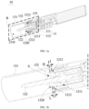
- FIG. 4 is an overall structural schematic view of the aerosol-forming device according to another embodiment of the present disclosure
- FIG. 5 is an exploded schematic view of the aerosol-forming device in FIG. 4
- FIG. 6 is a structural schematic view of a contact position between a fixing assembly and a heating assembly according to an embodiment of the present disclosure
- FIG. 7 is a schematic cross-sectional view of the aerosol-forming device in FIG. 4 along a B-B direction
- FIG. 8 is another schematic cross-sectional view of the aerosol-forming device in FIG. 4 along a B-B direction.
- an aerosol-forming device 10 is provided.
- the aerosol-forming device 10 includes a host 11, a heating assembly 12, and a fixing assembly 13.
- the host 11 may include a housing 111 and an inner base 112.
- the inner base 112 is arranged in the housing 111, and a receiving groove 1120 is defined in the inner base 12.
- the heating assembly 12 is at least partially received in the receiving groove 1120 and is electrically connected to the host 11.
- the host 11 further includes a power supply assembly.
- the power supply assembly is arranged in the housing 111. When the heating assembly 12 is received in the receiving groove 1120, the heating assembly 12 is connected to the power supply assembly of the host 11, and the power supply assembly may be configured to supply power to the heating assembly 12.
- the heating assembly 12 is electrically connected to the host 11 in a contact manner with a spring pin or pogo pin.
- the host 11 may be in a cylindrical shape, and the shape of the cross-sectional area of the host 11 may be circular, elliptical, or polygonal.
- the heating assembly 12 is configured to heat and atomize the aerosol-forming substance when energized.
- the heating assembly 12 may include a fixing mount 121 and a heating body 122.
- the fixing mount 121 is at least partially received in the receiving groove 1120.
- the heating body 122 is arranged on the fixing mount 121.
- the heating body 122 is electrically connected to the power supply assembly of the host 11, so as to heat and atomize the aerosol-forming substance after the heating body 122 is energized.
- the bottom wall of the receiving groove 1120 is arranged with a power interface.
- the end of the heating body 122 extends to the side surface of the fixing mount 121 facing the bottom wall of the receiving groove 1120.
- the end of the heating body 122 is in contact with the power interface, and is electrically connected to the power supply assembly via the power interface.
- the fixing mount 121 may include a fixing base 1211 and a limiting portion 1212.
- the limiting portion 1212 is arranged along the peripheral direction of the fixing base 1211.
- the shape of the fixing base 1211 may be cylindrical.
- the fixing base 1211 may be at least partially received in the receiving groove 1120, and the heating body 122 is fixed on the fixing base 1211.
- the outer diameter of the fixing base 1211 may be substantially consistent with the diameter of the receiving groove 1120. In this case, it may be possible to ensure that the heating body 122 may be in close contact with the interface of the power supply assembly, thereby ensuring effective connection between the heating body 122 and the power supply assembly.
- the limiting portion 1212 may be a ring-shaped flange arranged on the outer sidewall of the fixing base 1211, and may be arranged around the peripheral direction of the fixing base 1211. In addition, the limiting portion 1212 may be located on the end of the fixing base 1211 close to the heating body 122.
- the outer diameter of the limiting portion 1212 is greater than the diameter of the receiving groove 1120, such that after the heating body 122 is connected to the power supply assembly, the limiting portion 1212 may be in contact with the end surface of the inner base 112, that is, the limiting portion 1212 may be in contact with the end surface of the end where the notch of the receiving groove 1120 is located.
- the outer diameter of the limiting portion 1212 may be interpreted as the diameter of the pattern or contour corresponding to the outer surface of the limiting portion 1212.
- the outer diameter of the limiting portion 1212 may be substantially consistent with the inner diameter of the housing 111, such that the inner sidewall of the housing 111 may be configured to limit the limiting portion 1212 in the radial direction of the limiting portion 1212, thereby preventing the heating assembly 12 from shaking along the radial direction thereof.
- the fixing assembly 13 is detachably connected to the host 11, and when the fixing assembly 13 is connected to the host 11, the heating assembly 13 is at least partially in contact with the fixing assembly 12, so as to fix the heating assembly 12 in the receiving groove 1120 of the host 11.
- the fixing assembly 13 abuts against the at least part of the heating assembly 12, so as to improve fixing effect.
- the fixing assembly 13 may be in contact with the limiting portion 1212 of the fixing mount 121.
- the heating assembly 12 may be fixedly connected to the host 11 only via the fixing assembly 13.
- the heating assembly 12 is fixed in the receiving groove 1120 of the host 11 via the fixing assembly 13, and the fixing assembly 13 is detachably connected to the host 11.
- the heating assembly 12 when it is necessary to replace or clean the heating assembly 12, it is only necessary to disassemble the fixing assembly 13, and thus the heating assembly 12 may be separated from the host 11. After the replacement or cleaning is completed, the fixing assembly 13 is reconnected to the host 11, and thus the heating assembly 12 may be fixed to the host 11 again. Compared with the solution of fixing the heating assembly 12 to the host 11, it may be more convenient to replace and clean the heating assembly 12.
- the fixing assembly 13 may be a hollow tubular body.
- the tube diameter or inner diameter of the hollow tubular body is smaller than the outer diameter of the limiting portion 1212, and the tube diameter or inner diameter of the hollow tubular body may be further smaller than the diameter of the receiving groove 1120, such that the sidewall of the hollow tubular body may be configured to contact with the limiting portion 1212, thereby fixing the heating assembly 12 to the host 11.
- the fixing assembly 13 may include a fixing body 131 and a first pressing portion 132 arranged on the fixing body 131.
- the fixing body 131 may be a hollow tubular body, and a receiving cavity 1310 configured to accommodate the aerosol-forming substance may be defined in the fixing body 131.
- the first pressing portion 132 may be arranged on the inner wall surface of the tubular fixing body 131.
- the first pressing portion 132 of the fixing assembly 13 is in contact with the limiting portion 1212 of the heating assembly 12, so as to clamp the limiting portion 1212 between the first pressing portion 132 and the sidewall of the inner base 112, thereby fixing the heating assembly 12 to the host 11.
- the heating body 122 penetrates the first pressing portion 132 and extends into the receiving cavity 1310, so as to heat and atomize the aerosol-forming substance after the heating body 122 is energized.
- the fixing body 131 may be a tubular body defining or having openings at two ends, and the shape of the cross-sectional area of the fixing body 131 may be circular or polygonal. As shown in FIG. 3a or FIG. 7 , the first pressing portion 132 may be arranged at the end of the tubular body configured to connect to the end of the host 11, and is located in the tubular body. In some embodiments, embodiments, the fixing body 131 may be integrally formed with the first pressing portion 132.
- a through hole 1320 may be defined on the first pressing portion 132.
- the part of the heating body 122 protruding from the fixing mount 121 may be extended into the receiving cavity 1310 via the through hole 1320, such that the heating body 122 may avoid the first pressing portion 132. In this way, it may be possible to heat the aerosol-forming substance embedded in the receiving cavity 1310 and facilitate the cleaning of the heating body 122.
- the shape of the through hole 1320 may be substantially consistent with that of the heating body 122, and the diameter or inner diameter of the through hole 1320 may be substantially consistent with the outer diameter of the heating body 122, such that the sidewall of the through hole 1320, i.e., the first pressing portion 132, may be configured to scrape off a residue on the heating body 122.
- the first pressing portion 132 may limit the heating body 122 along the radial direction of the heating body 122, so as to prevent the heating assembly 12 from shaking along the radial direction thereof.
- the central axis of the through hole 1320 may substantially coincide with the central axis of the tubular fixing assembly 13, that is, the central axis of the through hole 1320 may be substantially co-linear with the central axis of the tubular fixing assembly 13.
- the distance between the heating body 122 and the inner sidewall of the fixing assembly 13 is the same in each direction, that is, the heating body 122 is in the central position of the fixing assembly 13, such that the heating body 122 may centrally heat the aerosol-forming substance inserted into the fixing assembly 13, thereby improving the uniformity of heating.
- the diameter or inner diameter of the through hole 1320 may also be greater than the radial size of the heating body 122.
- the shape of the through hole 1320 may match the external contour of the fixing base 1211.
- the diameter or inner diameter of the through hole 1320 is substantially consistent with the outer diameter of the fixing base 1211.
- the limiting portion 1212 is located on the end of the fixing base 1211 close to the first pressing portion 132.
- the linear distance L between the limiting portion 1212 and the end surface S of the end of the fixing base 1211 close to the first pressing portion 132 is the same size as the thickness H of the first pressing portion 132.
- the part of the fixing base 1211 located on the side of the limiting portion 1212 close to the first pressing portion 132 may be embedded in the through hole 1320 defined by the first pressing portion 132, so as to limit the fixing base 1211 along the radial direction thereof through the first pressing portion 132, thereby preventing the heating assembly 12 from shaking back and forth along the radial direction thereof.
- the first pressing portion 132 may be a protrusion portion arranged on the inner side wall of the tubular body.
- the protrusion portion may be a ringed-shape flange, and the ringed-shape flange is arranged in a circle along the peripheral direction of the tubular body.
- the protrusion portion may further include a plurality of protruding blocks.
- the plurality of protruding blocks are arranged at intervals along the peripheral direction of the tubular body, and the through hole 1320 is defined on the end of each of several protruding blocks away from the inner wall surface of the tubular body, and is configured to allow the heating body 122 of the heating assembly 12 to pass through.
- the plurality of protruding blocks may be arranged at equal intervals along the peripheral direction of the tubular body.
- the fixing assembly 13 may further include a second pressing portion 133.
- the second pressing portion 133 is connected to the fixing body 131, extends along the length direction of the fixing body 131 and facing away from the fixing body 131, and configured to limit the heating assembly 12 in the radial direction of the fixing mount 121.
- the second pressing portion 133 may be a tubular body, and the tube diameter or inner diameter of the tubular second pressing portion 133 is substantially consistent with the outer diameter of the limiting portion 1212, so as to limit the limiting portion 1212 in the radial direction of the limiting portion 1212, thereby fixing the heating assembly 12 in the radial direction of the heating assembly 12.
- a stopping portion 1121 is further arranged on the outer sidewall of the inner base 112 away from the end of a pressing assembly. After the pressing assembly is connected to the host 11, the end of the second pressing portion 133 away from the fixing body 131 is in contact with the stopping portion 1121.
- the fixing assembly 13 may be detachably connected to the host 11 via a thread.
- a first tubular connection portion is arranged on the end of the fixing assembly 13 facing the host 11.
- a second tubular connection portion is arranged on the end of the host 11 facing the fixing assembly 13.
- the outer sidewall of one of the first tubular connection portion of the fixing assembly 13 and the second tubular connection portion of the host 11 is arranged with an external thread
- the inner sidewall of the other of the first tubular connection portion of the fixing assembly 13 and the second tubular connection portion of the host 11 is arranged with an internal thread, such that the first tubular connection portion is threadedly connected to the second tubular connection portion through the external thread and the internal thread.
- the housing 111 includes a first housing portion 1112 and a second housing portion 1113 axially connected to the first housing portion 1112.
- the first housing portion 1112 is arranged with the second tubular connection portion of the host 11.
- the external thread is arranged on the outer sidewall of the first housing portion 1112, and the internal thread is arranged on the inner sidewall of the first tubular connection portion.
- the internal thread may be arranged on the inner sidewall of the second pressing portion 133.
- the outer diameter of the first housing portion 1112 may be smaller than the outer diameter of the second housing portion 1113, and the difference between the outer diameter of the first housing portion 1112 and the outer diameter of the second housing portion 1113 is substantially consistent with or equal to the wall thickness of the tube wall of the fixing assembly 13. In this way, it may be possible to ensure that the outer diameter of the fixing assembly 13 is substantially consistent with that of the host 11 after the fixing assembly 13 is rotated into the host 11, so as to improve the overall coordination of the product and increase the overall aesthetic of the product.
- the fixing assembly 13 is detachably connected to the host 11 via an engaging portion 134.
- one of the first tubular connection portion of the fixing assembly 13 and the second tubular connection portion of the host 11 is arranged with the engaging portion 134, and the other of the fixing assembly 13 and the second tubular connection portion of the host 11 is arranged with an engaging groove 1111, such that the first tubular connection portion is engaged with the second tubular connection portion.
- the engaging portion 134 may be arranged on the first tubular connection portion of the fixing assembly 13 and located on the outer wall surface of the first tubular connection portion.
- the engaging groove 1111 may be defined on the second tubular connection portion of the host 11.
- the engaging groove 1111 may include a guiding groove 111a and a clamping groove 111b that communicate with each other.
- the guiding groove 111a extends from the end surface of the host 11 at the end of the host 11 facing the fixing assembly 13 toward the end of the host 11 away from the fixing assembly 13, that is, the guiding groove 111a is an open groove.
- the open groove faces the first tubular connection portion, such that the engaging portion 134 of the first tubular connection portion may enter the guiding groove 111a.
- the clamping groove 111b extends along the peripheral direction of the host 11. After the engaging portion 134 enters the guiding groove 111a, the engaging portion 134 moves along the guiding groove 111a until the engaging portion 134 moves to the position where the guiding groove 111a communicates with the clamping groove 111b, and then the first tubular connection portion and the second tubular connection portion are caused to move relatively in the radial direction. In this way, it may be possible to cause the engaging portion 134 to slide into the clamping groove 111b, and thus the fixing assembly 13 may be engaged with the host 11.
- the fixing body 131 may include a first body portion 131a and a second body portion 131b.
- the outer diameter of the first body portion 131a is greater than the outer diameter of the second body portion 131b, and the outer diameter of the first body portion 131a may be substantially equal to the outer diameter of the host 11.
- the first tubular connection portion is arranged on the second body potion 131b, the engaging portion 134 is arranged on the outer side surface of the second body potion 131b, and the height of the engaging portion 134 is substantially consistent with or equal to the difference between the outer diameter of the first body potion 131a and the outer diameter of the second body potion 131b.
- the end of the engaging portion 134 away from the second body potion 131b is flush with the outer surface of the first body potion 131a, and thus it may be possible to ensure that the outer surface of the aerosol-forming device 10 is flush, and the overall curve of the aerosol-forming device 10 is more coordinated, thereby effectively increasing the overall aesthetic of the product.
- a receiving groove 1120 is defined on the host 11, such that the heating assembly 12 is at least partially received in the receiving groove 1120, and thus the heating assembly 12 may be electrically connected to the host 11.
- the fixing assembly 13 is detachably connected to the host 11, and after the fixing assembly 13 is connected to the host 11, the heating assembly 13 is partially in contact with the fixing assembly 12, so as to fix the heating assembly 12 to the host 11.
- the heating assembly 12 is fixedly in contact with the receiving groove 1120 of the host 11 via the fixing assembly 13, and the fixing assembly 13 is detachably connected to the host 11, such that when it is necessary to replace or clean the heating assembly 12, it is only necessary to disassemble the fixing assembly 13, and thus the heating assembly 12 may be separated from the host 11. In this way, it may be possible to allow users to replace the heating assembly 12 by themselves, and thus it may be more convenient to replace and clean the heating assembly 12.
Landscapes
- Chemical & Material Sciences (AREA)
- Organic Chemistry (AREA)
- Dispersion Chemistry (AREA)
- Chemical Kinetics & Catalysis (AREA)
- Resistance Heating (AREA)
- Containers And Packaging Bodies Having A Special Means To Remove Contents (AREA)
- Catching Or Destruction (AREA)
Applications Claiming Priority (2)
| Application Number | Priority Date | Filing Date | Title |
|---|---|---|---|
| CN202121482233.1U CN215898888U (zh) | 2021-06-30 | 2021-06-30 | 气溶胶形成装置 |
| PCT/CN2022/092853 WO2023273642A1 (zh) | 2021-06-30 | 2022-05-13 | 气溶胶形成装置 |
Publications (2)
| Publication Number | Publication Date |
|---|---|
| EP4364591A1 true EP4364591A1 (de) | 2024-05-08 |
| EP4364591A4 EP4364591A4 (de) | 2024-11-13 |
Family
ID=80288686
Family Applications (1)
| Application Number | Title | Priority Date | Filing Date |
|---|---|---|---|
| EP22831469.6A Pending EP4364591A4 (de) | 2021-06-30 | 2022-05-13 | Aerosolerzeugungsvorrichtung |
Country Status (4)
| Country | Link |
|---|---|
| EP (1) | EP4364591A4 (de) |
| KR (1) | KR20240027741A (de) |
| CN (1) | CN215898888U (de) |
| WO (1) | WO2023273642A1 (de) |
Families Citing this family (2)
| Publication number | Priority date | Publication date | Assignee | Title |
|---|---|---|---|---|
| EP4030938B1 (de) * | 2019-09-20 | 2023-11-01 | Philip Morris Products S.A. | Reinigungswerkzeug mit zusätzlichen reinigungselementen für eine aerosolerzeugungsvorrichtung |
| CN215898888U (zh) * | 2021-06-30 | 2022-02-25 | 深圳麦时科技有限公司 | 气溶胶形成装置 |
Family Cites Families (13)
| Publication number | Priority date | Publication date | Assignee | Title |
|---|---|---|---|---|
| CN207653580U (zh) * | 2015-11-03 | 2018-07-27 | 惠州市吉瑞科技有限公司深圳分公司 | 一种电子烤烟 |
| KR102138873B1 (ko) * | 2016-12-16 | 2020-07-29 | 주식회사 케이티앤지 | 히터를 사전예열하는 에어로졸 생성 시스템 |
| WO2018190603A1 (ko) * | 2017-04-11 | 2018-10-18 | 주식회사 케이티앤지 | 이동식 히터를 구비한 에어로졸 생성 장치 |
| KR102035313B1 (ko) * | 2017-05-26 | 2019-10-22 | 주식회사 케이티앤지 | 히터 조립체 및 이를 구비한 에어로졸 생성 장치 |
| EP3711539A1 (de) * | 2019-03-22 | 2020-09-23 | Nerudia Limited | Erwärmungssystem ohne verbrennung |
| CN211860585U (zh) * | 2020-02-26 | 2020-11-03 | 深圳麦时科技有限公司 | 加热件及电磁加热烘烤装置 |
| CN212164902U (zh) * | 2020-03-20 | 2020-12-18 | 云南中烟工业有限责任公司 | 一种加热组件可更换的加热不燃烧烟具 |
| CN212164899U (zh) * | 2020-04-30 | 2020-12-18 | 南通金源新材料有限公司 | 一种易于清洁的加热器具 |
| CN111616418A (zh) * | 2020-06-29 | 2020-09-04 | 深圳市吉迩科技有限公司 | 一种可拆卸的压紧机构及气凝胶发生装置 |
| CN112107032A (zh) * | 2020-10-19 | 2020-12-22 | 云南中烟工业有限责任公司 | 一种组件可拆卸的加热不燃烧烟具及其清洁方法 |
| CN214179146U (zh) * | 2020-12-21 | 2021-09-14 | 东莞市麦斯莫科电子科技有限公司 | 可拆卸的加热不燃烧电子烟 |
| CN215898888U (zh) * | 2021-06-30 | 2022-02-25 | 深圳麦时科技有限公司 | 气溶胶形成装置 |
| CN215958356U (zh) * | 2021-08-02 | 2022-03-08 | 深圳市合元科技有限公司 | 加热组件以及气溶胶生成装置 |
-
2021
- 2021-06-30 CN CN202121482233.1U patent/CN215898888U/zh active Active
-
2022
- 2022-05-13 EP EP22831469.6A patent/EP4364591A4/de active Pending
- 2022-05-13 WO PCT/CN2022/092853 patent/WO2023273642A1/zh not_active Ceased
- 2022-05-13 KR KR1020247002929A patent/KR20240027741A/ko active Pending
Also Published As
| Publication number | Publication date |
|---|---|
| WO2023273642A1 (zh) | 2023-01-05 |
| KR20240027741A (ko) | 2024-03-04 |
| CN215898888U (zh) | 2022-02-25 |
| EP4364591A4 (de) | 2024-11-13 |
Similar Documents
| Publication | Publication Date | Title |
|---|---|---|
| EP4364591A1 (de) | Aerosolerzeugungsvorrichtung | |
| US12274304B2 (en) | Aerosol generating device | |
| EP3162230B1 (de) | Zerstäubungskopf, zerstäuber und elektronische zigarette damit | |
| US9861132B2 (en) | Atomizer and electronic cigarette having same | |
| EP3179828B1 (de) | Zigarettenerwärmungsvorrichtung | |
| EP2870889B1 (de) | Zerstäubungsanordnung, Zerstäuber und elektronische Zigarette damit | |
| EP3626094B1 (de) | Multifunktionale elektronische rauchvorrichtung zum umlaufenden erwärmen | |
| US9301549B2 (en) | Electronic cigarette device, electronic cigarette and atomization device thereof | |
| JP2018174784A (ja) | 喫煙具 | |
| CA2928155C (en) | Apparatus for heating smokable material | |
| RU2701570C2 (ru) | Нагревательные элементы, сформированные из листа материала, заготовки и способы изготовления атомайзеров и картриджа для устройства для доставки аэрозоля и способ сборки картриджа для курительного изделия | |
| CN110621176B (zh) | 加热器组件及具备该加热器组件的气溶胶生成装置 | |
| EP3777580B1 (de) | Gebackene rauchvorrichtung | |
| US20140060529A1 (en) | Cotton free e-cigarette vaporizer | |
| US20150351455A1 (en) | Electronic cigarette and electronic cigarette device thereof | |
| WO2013181796A1 (zh) | 电子烟及其吸杆 | |
| US20140373833A1 (en) | Electronic cigarette inhalation rod and electronic cigarette using the same | |
| WO2017075759A1 (zh) | 一种电子烤烟 | |
| WO2016065606A1 (zh) | 一种雾化器以及电子烟 | |
| JP2006320285A (ja) | 擬似タバコ用加熱装置および擬似タバコ | |
| CN105768228B (zh) | 电子烟雾化芯及电子烟雾化器 | |
| WO2016082179A1 (zh) | 雾化组件和电子烟 | |
| CN210203367U (zh) | 加热可抽吸材料的装置 | |
| CN110946330B (zh) | 一种电子雾化装置及其提取器 | |
| CN108618204B (zh) | 雾化器及电子烟 |
Legal Events
| Date | Code | Title | Description |
|---|---|---|---|
| STAA | Information on the status of an ep patent application or granted ep patent |
Free format text: STATUS: THE INTERNATIONAL PUBLICATION HAS BEEN MADE |
|
| PUAI | Public reference made under article 153(3) epc to a published international application that has entered the european phase |
Free format text: ORIGINAL CODE: 0009012 |
|
| STAA | Information on the status of an ep patent application or granted ep patent |
Free format text: STATUS: REQUEST FOR EXAMINATION WAS MADE |
|
| 17P | Request for examination filed |
Effective date: 20240125 |
|
| AK | Designated contracting states |
Kind code of ref document: A1 Designated state(s): AL AT BE BG CH CY CZ DE DK EE ES FI FR GB GR HR HU IE IS IT LI LT LU LV MC MK MT NL NO PL PT RO RS SE SI SK SM TR |
|
| DAV | Request for validation of the european patent (deleted) | ||
| DAX | Request for extension of the european patent (deleted) | ||
| A4 | Supplementary search report drawn up and despatched |
Effective date: 20241011 |
|
| RIC1 | Information provided on ipc code assigned before grant |
Ipc: B01J 13/02 20060101ALI20241007BHEP Ipc: B01J 13/00 20060101ALI20241007BHEP Ipc: A24F 40/85 20200101ALI20241007BHEP Ipc: A24F 40/20 20200101ALI20241007BHEP Ipc: A24F 40/46 20200101ALI20241007BHEP Ipc: A24F 40/40 20200101AFI20241007BHEP |