EP3777650A1 - Système de chirurgie endoluminale - Google Patents
Système de chirurgie endoluminale Download PDFInfo
- Publication number
- EP3777650A1 EP3777650A1 EP18912007.4A EP18912007A EP3777650A1 EP 3777650 A1 EP3777650 A1 EP 3777650A1 EP 18912007 A EP18912007 A EP 18912007A EP 3777650 A1 EP3777650 A1 EP 3777650A1
- Authority
- EP
- European Patent Office
- Prior art keywords
- connecting rod
- surgery system
- groove
- limiting part
- intracavitary
- Prior art date
- Legal status (The legal status is an assumption and is not a legal conclusion. Google has not performed a legal analysis and makes no representation as to the accuracy of the status listed.)
- Withdrawn
Links
- 238000001356 surgical procedure Methods 0.000 title claims abstract description 85
- 230000006378 damage Effects 0.000 abstract description 10
- 238000000338 in vitro Methods 0.000 abstract 3
- 238000010586 diagram Methods 0.000 description 19
- 210000000056 organ Anatomy 0.000 description 16
- 210000001519 tissue Anatomy 0.000 description 15
- 208000027418 Wounds and injury Diseases 0.000 description 10
- 208000014674 injury Diseases 0.000 description 8
- 238000000034 method Methods 0.000 description 7
- 238000000926 separation method Methods 0.000 description 7
- 239000007787 solid Substances 0.000 description 5
- 210000000683 abdominal cavity Anatomy 0.000 description 4
- 210000003484 anatomy Anatomy 0.000 description 4
- 230000006835 compression Effects 0.000 description 4
- 238000007906 compression Methods 0.000 description 4
- 238000002674 endoscopic surgery Methods 0.000 description 4
- 230000003902 lesion Effects 0.000 description 4
- 210000000115 thoracic cavity Anatomy 0.000 description 4
- 229910000967 As alloy Inorganic materials 0.000 description 3
- 229910000831 Steel Inorganic materials 0.000 description 3
- 238000002357 laparoscopic surgery Methods 0.000 description 3
- 239000000463 material Substances 0.000 description 3
- 239000010959 steel Substances 0.000 description 3
- 230000008901 benefit Effects 0.000 description 2
- 230000007423 decrease Effects 0.000 description 2
- 238000003780 insertion Methods 0.000 description 2
- 230000037431 insertion Effects 0.000 description 2
- 230000004048 modification Effects 0.000 description 2
- 238000012986 modification Methods 0.000 description 2
- 230000002792 vascular Effects 0.000 description 2
- 230000004308 accommodation Effects 0.000 description 1
- 230000009471 action Effects 0.000 description 1
- 230000002411 adverse Effects 0.000 description 1
- 238000004891 communication Methods 0.000 description 1
- 230000000694 effects Effects 0.000 description 1
- 238000001839 endoscopy Methods 0.000 description 1
- 230000007717 exclusion Effects 0.000 description 1
- 230000006872 improvement Effects 0.000 description 1
- 230000003993 interaction Effects 0.000 description 1
- 230000000968 intestinal effect Effects 0.000 description 1
- 210000004185 liver Anatomy 0.000 description 1
- 210000004072 lung Anatomy 0.000 description 1
- 210000003205 muscle Anatomy 0.000 description 1
- 230000008569 process Effects 0.000 description 1
- 238000012954 risk control Methods 0.000 description 1
- 231100000241 scar Toxicity 0.000 description 1
- 210000002784 stomach Anatomy 0.000 description 1
- 210000002435 tendon Anatomy 0.000 description 1
Images




Classifications
-
- A—HUMAN NECESSITIES
- A61—MEDICAL OR VETERINARY SCIENCE; HYGIENE
- A61B—DIAGNOSIS; SURGERY; IDENTIFICATION
- A61B17/00—Surgical instruments, devices or methods
- A61B17/28—Surgical forceps
- A61B17/29—Forceps for use in minimally invasive surgery
-
- A—HUMAN NECESSITIES
- A61—MEDICAL OR VETERINARY SCIENCE; HYGIENE
- A61B—DIAGNOSIS; SURGERY; IDENTIFICATION
- A61B17/00—Surgical instruments, devices or methods
- A61B17/00234—Surgical instruments, devices or methods for minimally invasive surgery
-
- A—HUMAN NECESSITIES
- A61—MEDICAL OR VETERINARY SCIENCE; HYGIENE
- A61B—DIAGNOSIS; SURGERY; IDENTIFICATION
- A61B17/00—Surgical instruments, devices or methods
- A61B17/34—Trocars; Puncturing needles
- A61B17/3417—Details of tips or shafts, e.g. grooves, expandable, bendable; Multiple coaxial sliding cannulas, e.g. for dilating
- A61B17/3421—Cannulas
-
- A—HUMAN NECESSITIES
- A61—MEDICAL OR VETERINARY SCIENCE; HYGIENE
- A61B—DIAGNOSIS; SURGERY; IDENTIFICATION
- A61B17/00—Surgical instruments, devices or methods
- A61B17/34—Trocars; Puncturing needles
- A61B17/3478—Endoscopic needles, e.g. for infusion
-
- A—HUMAN NECESSITIES
- A61—MEDICAL OR VETERINARY SCIENCE; HYGIENE
- A61B—DIAGNOSIS; SURGERY; IDENTIFICATION
- A61B17/00—Surgical instruments, devices or methods
- A61B17/00234—Surgical instruments, devices or methods for minimally invasive surgery
- A61B2017/00292—Surgical instruments, devices or methods for minimally invasive surgery mounted on or guided by flexible, e.g. catheter-like, means
- A61B2017/0034—Surgical instruments, devices or methods for minimally invasive surgery mounted on or guided by flexible, e.g. catheter-like, means adapted to be inserted through a working channel of an endoscope
-
- A—HUMAN NECESSITIES
- A61—MEDICAL OR VETERINARY SCIENCE; HYGIENE
- A61B—DIAGNOSIS; SURGERY; IDENTIFICATION
- A61B17/00—Surgical instruments, devices or methods
- A61B17/00234—Surgical instruments, devices or methods for minimally invasive surgery
- A61B2017/00349—Needle-like instruments having hook or barb-like gripping means, e.g. for grasping suture or tissue
-
- A—HUMAN NECESSITIES
- A61—MEDICAL OR VETERINARY SCIENCE; HYGIENE
- A61B—DIAGNOSIS; SURGERY; IDENTIFICATION
- A61B17/00—Surgical instruments, devices or methods
- A61B17/28—Surgical forceps
- A61B17/29—Forceps for use in minimally invasive surgery
- A61B2017/2926—Details of heads or jaws
- A61B2017/2931—Details of heads or jaws with releasable head
-
- A—HUMAN NECESSITIES
- A61—MEDICAL OR VETERINARY SCIENCE; HYGIENE
- A61B—DIAGNOSIS; SURGERY; IDENTIFICATION
- A61B17/00—Surgical instruments, devices or methods
- A61B17/28—Surgical forceps
- A61B17/29—Forceps for use in minimally invasive surgery
- A61B2017/2926—Details of heads or jaws
- A61B2017/2932—Transmission of forces to jaw members
-
- A—HUMAN NECESSITIES
- A61—MEDICAL OR VETERINARY SCIENCE; HYGIENE
- A61B—DIAGNOSIS; SURGERY; IDENTIFICATION
- A61B17/00—Surgical instruments, devices or methods
- A61B17/28—Surgical forceps
- A61B17/29—Forceps for use in minimally invasive surgery
- A61B2017/2926—Details of heads or jaws
- A61B2017/2932—Transmission of forces to jaw members
- A61B2017/2939—Details of linkages or pivot points
- A61B2017/2941—Toggle linkages
-
- A—HUMAN NECESSITIES
- A61—MEDICAL OR VETERINARY SCIENCE; HYGIENE
- A61B—DIAGNOSIS; SURGERY; IDENTIFICATION
- A61B17/00—Surgical instruments, devices or methods
- A61B17/34—Trocars; Puncturing needles
- A61B17/3417—Details of tips or shafts, e.g. grooves, expandable, bendable; Multiple coaxial sliding cannulas, e.g. for dilating
- A61B17/3421—Cannulas
- A61B2017/3445—Cannulas used as instrument channel for multiple instruments
Definitions
- the present invention relates to the field of surgical instruments, and particularly to an intracavitary surgery system.
- the present disclosure provides an intracavitary surgery system, which can reduce the injury to the patients because the rod diameter of intracavitary surgical instruments is very small.
- the intracavitary surgery system can help retract the tissues or organs during operation through a tiny needle wound which need no suture after surgery.
- an intracavitary surgery system there is provided an intracavitary surgery system.
- the intracavitary surgery system includes: a needle type connecting rod; an operating device including an operating part and a connecting part; and a handle for fixing the connecting rod.
- the connecting part is configured to be fixedly connected with the tip of the connecting rod in the body cavity.
- the connecting part includes: a fixing groove for accommodating the tip of the connecting rod.
- the fixing groove is provided with a first limiting part for fixing the connecting rod
- the tip of the connecting rod is provided with a second limiting part matched with the first limiting part.
- the tip of the connecting rod is configured to be fixedly connected with fixing groove by threads.
- the first limiting part includes at least one elastic ring.
- the second limiting part is provided with a clamping groove and a guide groove.
- the connecting rod is fixed with the elastic ring by the clamping groove, and is separated from the elastic ring by the guiding groove.
- the first limiting part is provided with a through-hole.
- the first limiting partis fixedly connected with the fixing groove by an elastic element.
- the through-hole is provided with a fixing buckle for fixing the connecting rod.
- the second limiting partis a clamping groove.
- the through-hole of the first limiting part is coaxially disposed with the fixing groove) to make the connecting rod go through the through-hole.
- the buckle in the through-hole is engaged with the clamping groove to fix the connecting rod.
- the first limiting partis an elastic jaw.
- the second limiting part is a clamping groove, and the clamping groove is configured to be fixedly connected with the jaw to fix the connecting rod.
- a rubber block may be arranged at one end of the fixing groove close to the operating part to protect the tip of the connecting rod.
- the connecting part further includes: a sliding groove arranged opposite to the fixing groove, a slider arranged in the sliding groove, and a pull line with one end fixedly connected with the slider to drive the slider to move.
- the slider and the operating part are connected.
- the intracavitary surgery system further includes: a hook needle with a groove or a hook arranged at the end.
- the connecting part further includes: a connecting piece extends along a side of the sliding groove.
- the operating partis a retractor clamp.
- the retractor clamp is connected with the connecting piece.
- the retractor clamp includes a first clamping arm and a second clamping arm.
- the first clamping arm and the second clamping arm are rotatably connected by a first hinge shaft.
- the first hinge shaft is provided with a first spring. Two ends of the first spring extend and are fixedly connected with the first clamping arm and the second clamping arm respectively.
- the diameter of the connecting rod is less than 5mm.
- the surface of the middle part of the connecting rod is provided with a frosted surface.
- the present disclosure provides an intracavitary surgery system.
- the intracavitary surgery system includes: an operating device, a connecting rod and a handle.
- the operating device includes an operating part and a connecting part.
- the operating device can be placed in the body cavity through an incision, and the tip of the connecting rod enters the body cavity through the piercing point and is fixedly connected with the connecting part of the operating device.
- the other end, outside the body, of the connecting rod is connected with the handle.
- the operating part can be controlled and adjusted through the handle outside the body to achieve the corresponding surgery procedures.
- the present disclosure reduces the injury to the patient's body, makes the surgical procedures outside the body more convenient, and improves the success rate of the operation.
- a connection may be a fixed connection, or a detachable connection, or an integrated connection; a connection may be a mechanical connection or an electric connection; a connection may be a direct connection, or an indirect connection via an intermediate medium, or may be an internal communication between two elements or an interaction between two elements.
- a connection may be a fixed connection, or a detachable connection, or an integrated connection; a connection may be a mechanical connection or an electric connection; a connection may be a direct connection, or an indirect connection via an intermediate medium, or may be an internal communication between two elements or an interaction between two elements.
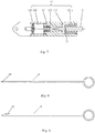
- FIG. 1 is a schematic diagram of an intracavitary surgery system of the present disclosure.
- the intracavitary surgery system includes an operating device, a connecting rod 2 and a handle 3.
- the connecting rod 2 may be a solid needle or a hollow needle. If the connecting part 12 is provided with a pull line 124, the connecting rod 2 is a hollow needle.
- the operating device 1 is arranged in the thoracic or abdominal cavity for performing the corresponding operation on a lesion of the patient. Referring to FIG. 2 , during the surgery, the surgeon makes an incision B on the patient's body surface A according to needs, and then inserts a trocar C corresponding to the size of the incision B for forming a passage for entry or exit of the surgical instruments.
- the surgeon places the operating device 1 through the trocar C into the body cavity D.
- the hollow needle 2 is fixedly connected with the handle 3, and the tip of the hollow needle 2 is pierced into the patient's body cavity D through another position on the patient's body surface A.
- the hollow needle 2 is fixedly connected with the operating device 1, and then, other surgical instrument such as an endoscope is placed in the body cavity D through the trocar C.
- the surgeon can control the operating device 1 through the handle 3 outside the body and perform the corresponding operation. For example, after clamping the organ F, the operation is performed by controlling the handle 3 for exposing the needed position.
- the handle 3 can control the operating device 1 via the pull line 124, or the operating part 1 can be controlled by the handle 3 in a non-line manner via its own structure.
- the handle 3 controls the operating device 1 by the pull line 124 and the hollow needle 2 is fixedly connected with the operating device 1, the hook needle 4 is inserted into the body cavity D through the end of the hollow needle 2 connected with the handle 3 in the direction of the straight arrow as shown in FIG. 2 .
- the pull line 124 is connected with the handle 3, so that the pull line 124 fixed to the operating device 1 can be took out of the body cavity and fixedly connected with the handle 3.
- multiple operating devices 1 can be placed in the body cavity to clamp different parts of the tissue so as to better expose the operation part.
- the intracavitary surgery system of the embodiments of present disclosure can help avoid the mutual interference between multiple surgical instruments which enter the body cavity through the same incision during surgery, where the mutual interference affects the flexibility of surgical operation such as anatomy or separation, and also can reduce the compression and injury around the incision.
- the operating device 1 includes an operating part 11 and a connecting part 12.
- the operating part 11 may be a retractor clamp, a pair of medical scissors or other surgical instrument suitable for an endoscopic surgery.
- the connecting part 12 includes a fixing groove 121, a sliding groove 122, a slider 123 and a pull line 124.
- a first limiting part 121a for fixing the connecting rod 2 is arranged in the fixing groove 121.
- the connecting rod 2 is a hollow needle.
- the tip of the hollow needle 2 is provided with a second limiting part 21 which is matched with the first limiting part 121a.
- the connecting part 12 can be made of materials with high strength and hardness such as alloy steel, which can improve the strength of the operating device 1, and can also be used for making small size structures to meet usage requirements.
- the first limiting part 121a may include at least one elastic ring, which is embedded in the fixing groove 121.
- the inner diameter of the elastic ring in the natural state is smaller than the outer diameter of the hollow needle 2, where the natural state refers to the state in which the elastic ring is not subjected to any external force.
- the second limiting part 21 may include a clamping groove 211 and a guide groove 212.
- the clamping groove 211 and the guide groove 212 are matched with the elastic ring.
- the clamping groove 211 and the guide groove 212 may be placed successively from the tip of the hollow needle 2 to a fixed end of the connecting rod 2.
- the clamping groove 211 is smaller than the guide groove 212.
- the elastic ring When the tip of the hollow needle 2 enters the fixing groove 121, the elastic ring is pressed into the fixing groove 121. Due to the small accommodation space of the clamping groove 211, the elastic ring forms an included angle with the insertion direction of the hollow needle 2. At this time, the pulling-out direction of the hollow needle 2 is different from the included angle of the elastic ring, so a resistance is relatively large, and it is difficult to pull out the hollow needle 2. When it needs to separate the hollow needle 2 from the connecting part 12 after the surgery is finished, the surgeon may insert the hollow needle 2 into the fixing groove 121 further. Since the insertion direction of the hollow needle 2 is the same as the included angle of the elastic ring, the resistance is relatively small, and the elastic ring can enter the guide groove 212 easily.
- the elastic ring returns to its natural state.
- the elastic ring is compressed into an angle in the same direction as the pulling-out direction. Since the resistance is relatively small, it is easy to pull out the hollow needle 2 from the fixing groove 121 to realize the separation.
- the first limiting part 121a may be set to an internal thread and the second limiting part 21 of the hollow needle 2 may be set to an external thread matched with the internal thread.
- the hollow needle 2 After the hollow needle 2 enters the body cavity through the piercing point, the hollow needle 2can be fixedly connected to the connecting part 12 by the threads.
- the first limiting part 121a may be set to an elastic buckle and the second limiting part 21 of the hollow needle 2 may be set to a clamping groove matched with the elastic buckle. After the hollow needle 2 enters the body cavity through the piercing point, the hollow needle 2 and the connecting part can be fixedly connected through the elastic buckle and the clamping groove.
- the first limiting part 121a may be set to an elastic jaw, which is in the fixing groove 121 and fixed to the end of the fixing groove 121.
- the second limiting part may be a clamping groove.
- the sliding groove 122 may be arranged on the side of the connecting part 12 opposite to the fixing groove 121, and the slider 123 may be placed in the sliding groove 122.
- One end of the slider 123 is connected with the operating part 11, and the operating part 11 is driven by the movement of the slider 123 in the sliding groove 122.
- the other end of the slider 123 is detachably connected with the pull line 124 for driving the operating part 11.
- the intracavitary surgery system further includes a hook needle 4.
- the hook needle 4 includes a groove 41 or a hook 42 disposed at an end of the hook needle 4.
- the diameter of the hook needle 4 is smaller than the inner diameter of the hollow needle 2.
- the operating part 11 is a retractor clamp.
- the surgeon can choose a specific retractor clamp according to the target tissues, such as a lung clamp, a stomach clamp, an intestinal clamp, a liver clamp, a tendon clamp, a vascular clamp, and the like.
- the retractor clamp may include a first clamping arm 111 and a second clamping arm 112.
- the first clamping arm 111 and the second clamping arm 112 may be rotatably connected through a first hinge shaft 113.
- the retractor clamp may be also connected with the connecting part 12 through the first hinge shaft 113.
- the inner surface of the first clamping arm 111 and the inner surface of the second clamping arm 112 may be provided with antiskid strips to prevent the tissues or organs from slipping out of the retractor clamp when the retractor clamp is in the close state.
- Each of the tail of the first clamping arm 111 and the tail of the second clamping arm 112 is provided with a mounting hole, and the two mounting holes are fixed with the connecting rod 114 and the connecting rod 115 respectively.
- the other ends of the connecting rod 114 and the connecting rod 115 are rotatably connected through a second hinge shaft 116. In the natural state (no external force is applied), an included angle between the connecting arms 114 and the connecting arms 115, and the retractor clamp is opened.
- a reset spring 13 may be arranged in the space between the slider 123 and the fixing groove 121.
- the surgeon may use handle 3 and the hollow needle 2 from outside to pull the operating part 11 to a position near the body cavity, and a vascular forceps can be used for fixation, so as not to cause an adverse effects for other intracavitary operations.
- the hollow needle 2 In the surgery, if the outer diameter of the hollow needle 2 is less than 5 mm, the hollow needle 2 enters the cavity through the piercing point, and after the hollow needle 2 is pulled out, because of the self-contracting function of muscles and skins, the piercing point caused by the hollow needle 2 may recover on its own and may no need to be sutured.
- the wound on the body surface is reduced by using the non-invasive manner.
- the hollow needle includes a tip and a fixed end. The tip of the hollow needle is configured to puncture into the body cavity and fixedly connect with the operating device 1, its outer diameter is 2mm, its inner diameter is 0.8mm, and its length is about 10cm.
- the fixed end is configured to be connected with the handle 3, and has an outer diameter of about 10mm and a length of about 10 cm.
- the middle part of the tip is provided with a frosted surface.
- the middle part of the tip may include several parts in the longitudinal direction, each of which has a predetermined length and is provided with a frosted surface.
- the middle part is a frosted rod between the tip and the fixed end, the frosted rod has a predetermined length, and two ends of the frosted rod are connected to the tip and the fixed end respectively.
- the outer surface of the frosted rod is set to be frosted, and its outer diameter and inner diameter are the same as the outer diameter and inner diameter of the tip respectively, and the frosted rod is coaxial with the tip and the fixing end.
- the predetermined length may be to 1 cm, or the predetermined length can be designed according to different surgeries or different patients.
- the frosted surface can increase the friction between the hollow needle and the wall of the body cavity, increase the tightness of the contact between the hollow needle and the wall of the body cavity, and avoid air leakage during the laparoscopic surgery for not affecting the surgery procedures.
- a rubber protecting block 14 may be arranged at the end of the fixing groove 121 to protect the tip of the hollow needle 2.
- the rubber block 14 is provided with a hole to facilitate the pull line to pass through.
- the handle 3 includes a bearing 31, a movable grip 32 and a fixed grip 33.
- the fixed grip 33 is provided with a mounting hole for fixing the fixed end of the hollow needle 2.
- the pull line 124 enters the hollow needle 2 through the tip of the hollow needle 2 and extends out the fixed end of the hollow needle 2, the pull line 124 is twined around the bearing in a predetermined direction and connected with a top end of the movable grip 32.
- the surgeon can control the pull line 124 to move within the hollow needle 2 by clenching or loosening the movable grip 32, which drives the retractor clamp to open or close and realizes the purpose of controlling the operating device 1 with the handle 3.
- the surgeon makes an incision B on the patient's body surface A according to needs, and then inserts a trocar C corresponding to the size of the incision B to the incision B to form a passage for entry or exit of the surgical instruments. Then, the surgeon places the operating device 1 through the trocar C into the body cavity D.
- the surgeon makes the handle 3 and the hollow needle 2 fixedly connected, and pierces the hollow needle into the body cavity through a selected piercing point on the body surface A.
- the hollow needle 2 is fixedly connected with the connecting part 12 of the operating device 1, the hook needle 4 enters the body cavity through the hollow needle 2 at the end of the handle 3, and the pull line 124 is pulled out of the body cavity by the hook needle 4 and is fixedly connected with the handle 3.
- the surgeon can control the pull line 124 to move in the connecting part 12, and thus can control the retractor clamp to clamp the organ that needs to be exposed.
- the organs can be exposed accurately.
- multiple operating devices 1 can be placed in the body cavity to clamp different parts of the tissue so as to better expose the operation part.
- the retractor clamp is opened by adjusting the length of the pull line 124, and then the pull line 124 is disconnected from the handle 3, so that the hollow needle 2 is separated from the connecting part 12 of the operating device 1.
- the hollow needle 2 is pulled out from the body, and the operating devices 1 can be taken out of the body cavity through the trocar C.
- the incision is sutured to finish the operation.
- the hollow needle 2 is directly cut off, and then the operating device 1 can be taken out of the body though the incision.
- the intracavitary surgery system of the present embodiment is a non-invasive surgery system and can reduce the injury to the body of the patient. Furthermore, with the intracavitary surgery system of the present embodiment, the pull force and pull direction can be more conveniently adjusted outside the body.
- FIG. 10 and FIG. 11 are schematic diagrams of an intracavitary surgery system according to the second embodiment of the present disclosure.
- the connecting rod 2 is a hollow needle.
- the intracavitary surgery system includes an operating device 1, a connecting rod 2 and a handle 3.
- the operating device 1 is arranged in the thoracic or abdominal cavity for performing the corresponding operation on a lesion of the patient.
- the surgeon makes an incision on the patient's body surface according to needs for forming a passage for entry or exit of the surgical instruments, and then places the operating device 1 through the incision into the body cavity.
- the hollow needle 2 is fixedly connected with the handle 3.
- the tip of the hollow needle 2 is pierced into the body cavity through the body surface and is fixedly connected with the operating device 1.
- the surgeon can control the operating device 1 through the handle 3 outside the body and perform the corresponding operation, which can help avoid the mutual interference between multiple surgical instruments which enter the body cavity through the same incision during surgery, where the mutual interference affects the flexibility of surgical operation such as anatomy or separation, and also can reduce the compression and injury around the incision.
- multiple operating devices 1 can be placed in the body cavity to clamp different parts of the tissue so as to better expose the operation part.
- the structure of the intracavitary surgery system is basically the same as the structure of the intracavitary surgery system of the first embodiment of the present disclosure.
- the difference between the two is, when the operating part 11 is a retractor clamp with a first spring 117, the reset spring may be not provided in the connecting part 12 according to needs.
- the retractor clamp may include a first clamping arm 111 and a second clamping arm 112.
- the first clamping arm 111 and the second clamping arm 112 may be rotatably connected through a first hinge shaft 113.
- the first spring 117 is disposed on the first hinge shaft 113. Two ends of the first spring 117 extend and are fixedly connected with the first clamping arm 111 and the second clamping arm 112 respectively.
- the retractor clamp may be also connected with the connecting part 12 through the first hinge shaft 113.
- the inner surface of the first clamping arm 111 and the inner surface of the second clamping arm 112 may be provided with antiskid strips to prevent the tissues or organs from slipping during the closing of the retractor clamp.
- Each of the tail of the first clamping arm 111 and the tail of the second clamping arm 112 is provided with a mounting hole, and the two mounting holes are fixed with the connecting rod 114 and the connecting rod 115 respectively.
- the other ends of the connecting rod 114 and the connecting rod 115 are rotatably connected through a second hinge shaft 116. In the natural state, there is an included angle between the connecting rod 114 and the connecting rod 115, and the retractor clamp is close.
- the included angle between the connecting rod 114 and the connecting rod 115 decreases gradually, which drives the first clamping arm 111 and the second clamping arm 112 to rotate relatively, and the retractor clamp is in the open state.
- the retractor clamp is moved to the target tissue or organ, the handle is released, and the retractor clamp returns to the natural state and is in the close state because of the elasticity of the first spring 117 so that the target tissue or organ is clamped. Finally, the clamped tissue or organ is moved as needed to provide a good surgical field of view.
- the structures of the connecting part 12, the hollow needle 2, the hook needle 4 and the handle 3 in this embodiment are similar to those in the first embodiment, so they will not be repeated here.
- the intracavitary surgery system includes an operating device 1, a connecting rod 2 and a handle 3.
- the connecting rod 2 is a hollow needle.
- the operating device 1 is arranged in the thoracic or abdominal cavity for performing the corresponding operation on a lesion of the patient.
- the surgeon makes an incision on the patient's body surface according to needs for forming a passage for entry or exit of the surgical instruments, and then places the operating device 1 through the incision into the body cavity.
- the hollow needle 2 is fixedly connected with the handle 3.
- the tip of the hollow needle 2 is pierced into the body cavity through the body surface and is fixedly connected with the operating device 1.
- the surgeon can control the operating device 1 through the handle 3 outside the body and perform the corresponding operation, which can help avoid the mutual interference between multiple surgical instruments which enter the body cavity through the same incision during surgery, where the mutual interference affects the flexibility of surgical operation such as anatomy or separation, and also can reduce the compression and injury around the incision. If necessary, multiple operating devices 1 can be placed in the body cavity to clamp different parts of the tissue so as to better expose the operation part.
- the operating device 1 includes an operating part 11 and a connecting part 12.
- the operating part 11 may be a retractor clamp, a pair of medical scissors or other surgical instrument suitable for an endoscopic surgery.
- the connecting part 12 includes a fixing groove 121, a sliding groove 122, a slider 123 and a pull line 124.
- a first limiting part 121a for fixing the connecting rod 2 is arranged in the fixing groove 121.
- the fixing groove 121 is provided with a limiting groove 121b in a longitudinal direction, which is used for accommodating the first limiting part 121a.
- the tip of the hollow needle 2 is provided with a second limiting part 21 which is matched with the first limiting part 121a.
- the connecting part 12 can be made of materials with high strength and hardness such as alloy steel, which can improve the strength of the operating device 1, and can also be used for making small size structures to meet usage requirements.
- the other structures of hollow needle 2 are similar to those in the first embodiment and will not be described here.
- the first limiting part 121a may be set to a movable buckle.
- the first limiting part 121a is fixedly connected to the fixing groove 121 through an elastic element 121c, and moves in the limiting groove according to the elasticity of the elastic element 121c.
- the movable buckle may be provided with a through-hole, and a fixing buckle is disposed in the through-hole for fixing the hollow needle 2.
- the second limiting part 2l isa clamping groove. In the first state, the through-hole of the first limiting part 121a is coaxial with the fixing groove 121 so that the hollow needle 2 can pass through the through-hole.
- the fixing buckle in the through-hole is mates with the clamping grooves to fix the hollow needle 2.
- the center axis of the through-hole of the first limiting part 121a is parallel to the center axis of the fixing groove 121 so that the hollow needle 2 cannot pass through the through-hole.
- the center axis of the through-hole of the first limiting part 121a approximately coincides with the center axis of the fixing groove 121 so that the hollow needle 2 can pass through the through-hole.
- the structures of the operating part 11, the handle 3 the hook needle 4 and the sliding groove 122, the slider 123 and the pull line 124 of the connecting part in this embodiment are similar to those in the first embodiment or the second embodiment, so they will not be repeated here.
- FIG. 15 and FIG. 16 are schematic diagrams of an intracavitary surgery system according to this embodiment of the present disclosure.
- the intracavitary surgery system includes an operating device 1, a connecting rod 2 and a handle 3.
- the connecting rod 2 may be a solid needle or a hollow needle.
- the operating device 1 is arranged in the thoracic or abdominal cavity for performing the corresponding operation on a lesion of the patient.
- the surgeon makes an incision on the patient's body surface according to needs for forming a passage for entry or exit of the surgical instruments, and then places the operating device 1 through the incision into the body cavity.
- the connecting rod 2 is fixedly connected with the handle 3.
- the tip of the connecting rod 2 is pierced into the body cavity through the body surface and is fixedly connected with the operating device 1.
- the surgeon can control the operating device 1 through the handle 3 outside the body and perform the corresponding operation, which can help avoid the mutual interference between multiple surgical instruments which enter the body cavity through the same incision during surgery, where the mutual interference affects the flexibility of surgical operation such as anatomy or separation, and also can reduce the compression and injury around the incision.
- the operating device 1 includes an operating part 11 and a connecting part 12.
- the operating part His a retractor clamp with a spring.
- the retractor clamp may include a first clamping arm 111 and a second clamping arm 112.
- the first clamping arm 111 and the second clamping arm 112 may be rotatably connected through a first hinge shaft 113.
- the first spring 117 is disposed on the first hinge shaft 113. Two ends of the first spring 117 extend and are fixedly connected with the first clamping arm 111 and the second clamping arm 112 respectively. Due to the elastic force of the first spring 117, the retractor clamp closes in the natural state (no external force is applied).
- the inner surface of the first clamping arm 111 and the inner surface of the second clamping arm 112 may be provided with antiskid strips to prevent the tissues or organs from slipping during the closing of the retractor clamp.
- the connecting part 12 may include a fixing groove 121 and a connecting piece 125.
- a first limiting part 121a for fixing the connecting rod 2 is arranged in the fixing groove 121.
- the tip of the connecting rod 2 is provided with a second limiting part 21 which is matched with the first limiting part 121a.
- the connecting part 12 can be made of materials with high strength and hardness such as alloy steel, which can improve the strength of the operating device 1, and can also be used for making small size structures to meet usage requirements.
- the first limiting part 121a may be set to an elastic jaw, which is embedded in an end of the fixing groove 121.
- the second limiting part 21 may be a clamping groove.
- first limiting part 121a and the second limiting part 21 may also be set to other structures, which are the same as the other first limiting part 121a and the second limiting part 21 in the first embodiment, respectively, and will not be repeated here.
- the connecting piece 125 is arranged on the side of the connecting part 12 opposite to the sliding groove 121 and extends along the sliding groove 121.
- the connecting piece 125 is further provided with a connecting hole.
- the first hinge shaft 113 extends through the connecting hole and connects the retractor clamp with the connecting part 12.
- the outer diameter of the hollow needle is generally less than 5 mm.
- the hollow needle includes a tip and a fixed end.
- the tip of the hollow needle is configured to puncture into the body cavity and fixedly connect with the operating device 1, its outer diameter is 2mm, its inner diameter is 0.8mm, and its length is about 10 cm.
- the fixed end is configured to be connected with the handle 3, and has an outer diameter of about 10mm and a length of about 10 cm.
- the middle part of the tip is provided with a frosted surface.
- the middle part of the tip may include several parts in the longitudinal direction, each of which has a predetermined length and is provided with a frosted surface.
- the middle part is a frosted rod between the tip and the fixed end, the frosted rod has a predetermined length, and two ends of the frosted rod are connected to the tip and the fixed end respectively.
- the outer surface of the frosted rod is set to be frosted, and its outer diameter and inner diameter are the same as the outer diameter and inner diameter of the tip respectively, and the frosted rod is coaxial with the tip and the fixing end.
- the predetermined length may be to 1 cm, or the predetermined length can be designed according to different surgeries or different patients.
- the frosted surface can increase the friction between the hollow needle and the wall of the body cavity, increase the tightness of the contact between the hollow needle and the wall of the body cavity, and avoid air leakage during the laparoscopic surgery for not affecting the surgery procedures.
- a rubber protecting block 14 may be arranged at the end of the fixing groove 121 to protect the tip of the hollow needle 2. If the connecting rod 2 is a solid needle, the diameter of the solid needle is less than 5 mm.
- the structure of the solid needle is basically similar to that of the hollow needle except that it has no inner hole.
- the operating device 1 is placed into the body cavity through an incision.
- the connecting rod 2 fixed with the handle 3 is pierced into the body cavity through a selected piercing point on the body surface.
- the connecting rod 2 is fixedly connected with the connecting part 12 of the operating device 1.
- the retractor clamp is controlled by handle 3 to move to the organ to be exposed, and then a separation forceps is sent into the cavity through the incision. Under the guidance of the endoscope, the separation forceps control the retractor clamp to hold the organs that need to be exposed. Then, the length of the connecting rod 2 in the body is adjusted through the handle 3 to achieve the precise exposing of the organ.
- the intracavitary surgery system in the present embodiment can reduce the damage to the patients and can facilitate the control of the retracting force and the retracting direction from outside of the body.
- the intracavitary surgery system of embodiments of the present embodiment includes an operating device, a connecting rod and a handle.
- the operating device includes an operating part and a connecting part.
- the operating device can be placed in the body cavity through an incision, and the tip of the connecting rod enters the body cavity through the piercing point and is fixedly connected with the connecting part of the operating device.
- the other end, outside the body, of the connecting rod is connected with the handle.
- the operating part can be controlled and adjusted through the handle outside the body to achieve the corresponding surgery procedures.
- the present disclosure provides a non-invasive way to reduce the injury to the patient's body, makes the surgical procedures outside the body more convenient, and improves the success rate of the operation.
Landscapes
- Health & Medical Sciences (AREA)
- Surgery (AREA)
- Life Sciences & Earth Sciences (AREA)
- Medical Informatics (AREA)
- Nuclear Medicine, Radiotherapy & Molecular Imaging (AREA)
- Engineering & Computer Science (AREA)
- Biomedical Technology (AREA)
- Heart & Thoracic Surgery (AREA)
- Molecular Biology (AREA)
- Animal Behavior & Ethology (AREA)
- General Health & Medical Sciences (AREA)
- Public Health (AREA)
- Veterinary Medicine (AREA)
- Pathology (AREA)
- Ophthalmology & Optometry (AREA)
- Surgical Instruments (AREA)
Applications Claiming Priority (1)
| Application Number | Priority Date | Filing Date | Title |
|---|---|---|---|
| PCT/CN2018/080972 WO2019183862A1 (fr) | 2018-03-28 | 2018-03-28 | Système de chirurgie endoluminale |
Publications (2)
| Publication Number | Publication Date |
|---|---|
| EP3777650A1 true EP3777650A1 (fr) | 2021-02-17 |
| EP3777650A4 EP3777650A4 (fr) | 2021-11-10 |
Family
ID=68059125
Family Applications (1)
| Application Number | Title | Priority Date | Filing Date |
|---|---|---|---|
| EP18912007.4A Withdrawn EP3777650A4 (fr) | 2018-03-28 | 2018-03-28 | Système de chirurgie endoluminale |
Country Status (3)
| Country | Link |
|---|---|
| EP (1) | EP3777650A4 (fr) |
| CN (1) | CN110545736B (fr) |
| WO (1) | WO2019183862A1 (fr) |
Cited By (1)
| Publication number | Priority date | Publication date | Assignee | Title |
|---|---|---|---|---|
| EP4434478A1 (fr) | 2023-03-23 | 2024-09-25 | Mao, Zhangfan | Système chirurgical, dispositif d'actionnement pour actionner un instrument chirurgical et instrument chirurgical associé |
Families Citing this family (9)
| Publication number | Priority date | Publication date | Assignee | Title |
|---|---|---|---|---|
| CN112957094B (zh) * | 2021-02-03 | 2022-06-10 | 中山大学附属第三医院(中山大学肝脏病医院) | 施夹器 |
| CN113143407B (zh) * | 2021-02-08 | 2022-08-23 | 中国人民解放军海军军医大学第一附属医院 | 一种可用于教学的小切口肠癌根治术手术抓钳 |
| CN112869815B (zh) * | 2021-02-15 | 2022-02-08 | 苏州法兰克曼医疗器械有限公司 | 一种带有可调式传动机构的内镜切割吻合器 |
| CN114272014B (zh) * | 2021-11-17 | 2024-05-07 | 南京市河西医院有限公司 | Fs胎式无痕重睑用夹取装置及其使用方法 |
| CN114129208A (zh) * | 2021-12-07 | 2022-03-04 | 西安赛德欧医疗研究院有限公司 | 一种适用于腔镜手术的磁性组织牵拉装置及医疗设备 |
| CN115500879A (zh) * | 2022-09-28 | 2022-12-23 | 苏州大学附属第二医院 | 用于腹腔镜手术的脏器牵拉装置 |
| CN115892959B (zh) * | 2023-01-09 | 2023-05-12 | 苏州锐杰微科技集团有限公司 | Pcb板冷却用接驳台及其工作方法 |
| CN117017473B (zh) * | 2023-08-31 | 2025-08-12 | 毛张凡 | 电凝手术器械 |
| CN119791785A (zh) * | 2025-01-25 | 2025-04-11 | 首都医科大学附属北京世纪坛医院 | 一种腔镜用微波电剪复合能量刀头 |
Family Cites Families (10)
| Publication number | Priority date | Publication date | Assignee | Title |
|---|---|---|---|---|
| US20050096502A1 (en) * | 2003-10-29 | 2005-05-05 | Khalili Theodore M. | Robotic surgical device |
| US8377044B2 (en) * | 2007-03-30 | 2013-02-19 | Ethicon Endo-Surgery, Inc. | Detachable end effectors |
| US8758391B2 (en) * | 2008-02-14 | 2014-06-24 | Ethicon Endo-Surgery, Inc. | Interchangeable tools for surgical instruments |
| DE102009015392A1 (de) * | 2009-03-20 | 2010-09-23 | Karl Storz Gmbh & Co. Kg | Medizinisches Instrument, insbesondere Hysteroskop |
| EP2618752B1 (fr) * | 2010-09-24 | 2021-04-28 | Ethicon Endo-Surgery, Inc. | Instrument laparoscopique équipé d'un organe effecteur amovible |
| CN102357042B (zh) * | 2011-10-20 | 2013-11-06 | 杭州康基医疗器械有限公司 | 内窥镜用多功能手术钳 |
| CN203089228U (zh) * | 2013-01-21 | 2013-07-31 | 宁波胜杰康生物科技有限公司 | 一种多自由度的手术器械 |
| US10058343B2 (en) * | 2013-03-14 | 2018-08-28 | Covidien Lp | Systems for performing endoscopic procedures |
| CN204890109U (zh) * | 2015-06-09 | 2015-12-23 | 华中科技大学同济医学院附属同济医院 | 带吸引器的腹腔镜手术抓钳 |
| CN206729915U (zh) * | 2016-08-25 | 2017-12-12 | 江苏省人民医院 | 一种可进行超声刀手术的内窥镜 |
-
2018
- 2018-03-28 WO PCT/CN2018/080972 patent/WO2019183862A1/fr not_active Ceased
- 2018-03-28 EP EP18912007.4A patent/EP3777650A4/fr not_active Withdrawn
- 2018-03-28 CN CN201880004550.7A patent/CN110545736B/zh active Active
Cited By (2)
| Publication number | Priority date | Publication date | Assignee | Title |
|---|---|---|---|---|
| EP4434478A1 (fr) | 2023-03-23 | 2024-09-25 | Mao, Zhangfan | Système chirurgical, dispositif d'actionnement pour actionner un instrument chirurgical et instrument chirurgical associé |
| WO2024194247A1 (fr) | 2023-03-23 | 2024-09-26 | Mao Zhangfan | Système chirurgical, dispositif d'actionnement d'instrument chirurgical, et instrument chirurgical associé |
Also Published As
| Publication number | Publication date |
|---|---|
| EP3777650A4 (fr) | 2021-11-10 |
| WO2019183862A1 (fr) | 2019-10-03 |
| CN110545736A (zh) | 2019-12-06 |
| CN110545736B (zh) | 2022-07-08 |
Similar Documents
| Publication | Publication Date | Title |
|---|---|---|
| EP3777650A1 (fr) | Système de chirurgie endoluminale | |
| US11793535B2 (en) | Endoluminal surgery device | |
| US10631855B2 (en) | Wound closure device including direct-driven needle | |
| US7306613B2 (en) | Endoscopic instruments | |
| US20200197042A1 (en) | Methods and devices for laparoscopic surgery | |
| US9480470B2 (en) | Suspension/retraction device for surgical manipulation | |
| JP4898709B2 (ja) | 経自然開口的または経皮的な医療システム | |
| US8038610B2 (en) | Medical instrument introduction device and method of introducing medical device | |
| CN110236613B (zh) | 腔内手术器械 | |
| JP2012024607A (ja) | 縫合器 | |
| CN209074718U (zh) | 腔内牵引装置 | |
| US9375228B2 (en) | Laparoscopic tool for grasping tissue | |
| US20070161864A1 (en) | Laparoscopic Tissue Retractor | |
| US8857441B2 (en) | Biological tissue transfer method and biological tissue treatment method | |
| US20250143691A1 (en) | Thread suturing endoscopic device |
Legal Events
| Date | Code | Title | Description |
|---|---|---|---|
| STAA | Information on the status of an ep patent application or granted ep patent |
Free format text: STATUS: THE INTERNATIONAL PUBLICATION HAS BEEN MADE |
|
| PUAI | Public reference made under article 153(3) epc to a published international application that has entered the european phase |
Free format text: ORIGINAL CODE: 0009012 |
|
| STAA | Information on the status of an ep patent application or granted ep patent |
Free format text: STATUS: REQUEST FOR EXAMINATION WAS MADE |
|
| 17P | Request for examination filed |
Effective date: 20200922 |
|
| AK | Designated contracting states |
Kind code of ref document: A1 Designated state(s): AL AT BE BG CH CY CZ DE DK EE ES FI FR GB GR HR HU IE IS IT LI LT LU LV MC MK MT NL NO PL PT RO RS SE SI SK SM TR |
|
| AX | Request for extension of the european patent |
Extension state: BA ME |
|
| DAV | Request for validation of the european patent (deleted) | ||
| DAX | Request for extension of the european patent (deleted) | ||
| A4 | Supplementary search report drawn up and despatched |
Effective date: 20211013 |
|
| RIC1 | Information provided on ipc code assigned before grant |
Ipc: A61B 17/00 20060101ALN20211007BHEP Ipc: A61B 17/29 20060101AFI20211007BHEP |
|
| STAA | Information on the status of an ep patent application or granted ep patent |
Free format text: STATUS: THE APPLICATION IS DEEMED TO BE WITHDRAWN |
|
| 18D | Application deemed to be withdrawn |
Effective date: 20220514 |