EP4434478A1 - Système chirurgical, dispositif d'actionnement pour actionner un instrument chirurgical et instrument chirurgical associé - Google Patents
Système chirurgical, dispositif d'actionnement pour actionner un instrument chirurgical et instrument chirurgical associé Download PDFInfo
- Publication number
- EP4434478A1 EP4434478A1 EP23163740.6A EP23163740A EP4434478A1 EP 4434478 A1 EP4434478 A1 EP 4434478A1 EP 23163740 A EP23163740 A EP 23163740A EP 4434478 A1 EP4434478 A1 EP 4434478A1
- Authority
- EP
- European Patent Office
- Prior art keywords
- coupling means
- wire
- connector
- surgical instrument
- actuating device
- Prior art date
- Legal status (The legal status is an assumption and is not a legal conclusion. Google has not performed a legal analysis and makes no representation as to the accuracy of the status listed.)
- Withdrawn
Links
Images




Classifications
-
- A—HUMAN NECESSITIES
- A61—MEDICAL OR VETERINARY SCIENCE; HYGIENE
- A61B—DIAGNOSIS; SURGERY; IDENTIFICATION
- A61B17/00—Surgical instruments, devices or methods
- A61B17/28—Surgical forceps
- A61B17/29—Forceps for use in minimally invasive surgery
-
- A—HUMAN NECESSITIES
- A61—MEDICAL OR VETERINARY SCIENCE; HYGIENE
- A61B—DIAGNOSIS; SURGERY; IDENTIFICATION
- A61B17/00—Surgical instruments, devices or methods
- A61B2017/0046—Surgical instruments, devices or methods with a releasable handle; with handle and operating part separable
- A61B2017/00473—Distal part, e.g. tip or head
-
- A—HUMAN NECESSITIES
- A61—MEDICAL OR VETERINARY SCIENCE; HYGIENE
- A61B—DIAGNOSIS; SURGERY; IDENTIFICATION
- A61B17/00—Surgical instruments, devices or methods
- A61B2017/00477—Coupling
-
- A—HUMAN NECESSITIES
- A61—MEDICAL OR VETERINARY SCIENCE; HYGIENE
- A61B—DIAGNOSIS; SURGERY; IDENTIFICATION
- A61B17/00—Surgical instruments, devices or methods
- A61B17/28—Surgical forceps
- A61B17/29—Forceps for use in minimally invasive surgery
- A61B2017/2926—Details of heads or jaws
- A61B2017/2927—Details of heads or jaws the angular position of the head being adjustable with respect to the shaft
- A61B2017/2929—Details of heads or jaws the angular position of the head being adjustable with respect to the shaft with a head rotatable about the longitudinal axis of the shaft
-
- A—HUMAN NECESSITIES
- A61—MEDICAL OR VETERINARY SCIENCE; HYGIENE
- A61B—DIAGNOSIS; SURGERY; IDENTIFICATION
- A61B17/00—Surgical instruments, devices or methods
- A61B17/28—Surgical forceps
- A61B17/29—Forceps for use in minimally invasive surgery
- A61B2017/2926—Details of heads or jaws
- A61B2017/2927—Details of heads or jaws the angular position of the head being adjustable with respect to the shaft
- A61B2017/2929—Details of heads or jaws the angular position of the head being adjustable with respect to the shaft with a head rotatable about the longitudinal axis of the shaft
- A61B2017/293—Details of heads or jaws the angular position of the head being adjustable with respect to the shaft with a head rotatable about the longitudinal axis of the shaft with means preventing relative rotation between the shaft and the actuating rod
-
- A—HUMAN NECESSITIES
- A61—MEDICAL OR VETERINARY SCIENCE; HYGIENE
- A61B—DIAGNOSIS; SURGERY; IDENTIFICATION
- A61B17/00—Surgical instruments, devices or methods
- A61B17/28—Surgical forceps
- A61B17/29—Forceps for use in minimally invasive surgery
- A61B2017/2926—Details of heads or jaws
- A61B2017/2931—Details of heads or jaws with releasable head
-
- A—HUMAN NECESSITIES
- A61—MEDICAL OR VETERINARY SCIENCE; HYGIENE
- A61B—DIAGNOSIS; SURGERY; IDENTIFICATION
- A61B17/00—Surgical instruments, devices or methods
- A61B17/28—Surgical forceps
- A61B17/29—Forceps for use in minimally invasive surgery
- A61B2017/2946—Locking means
Definitions
- the present disclosure relates in general to the field of surgical systems and instruments for multi-incision minimally invasive surgery, e.g., surgical instruments for thoracoscopic or laparoscopic surgery. These are also referred to as surgical instruments for intracavitary surgery or endoluminal surgery.
- the present disclosure relates to surgical systems, comprising a surgical instrument, and an actuating device for actuating the surgical instrument, the actuating device comprising a connector having a connector longitudinal axis in which a hollow channel extends along the longitudinal axis between a distal end and a proximal end, wherein the distal end is provided with a first coupling means configured to be coupled to a first mating coupling means on the surgical instrument, wherein said hollow channel axially movably receives a wire having a longitudinal wire axis essentially parallel with the connector longitudinal axis, and said wire having a distal wire end and a proximal wire end, said distal wire end being provided with a second coupling means configured to be connected to a second mating coupling means on the surgical instrument, said first coupling means being configured to be connectable to said first mating coupling means by rotation of said connector about said connector longitudinal axis in a first rotational direction.
- the present invention further relates to an actuating device for actuating a surgical instrument, the actuating device comprising a connector having a connector longitudinal axis in which a hollow channel extends along the longitudinal axis between a distal end and a proximal end, wherein the distal end is provided with a first coupling means configured to be coupled to a first mating coupling means on the surgical instrument, wherein said hollow channel axially movable receives a wire having a longitudinal wire axis essentially parallel with the connector longitudinal axis, and said wire having a distal wire end and a proximal wire end, said distal wire end being provided with a second coupling means configured to be connected to a second mating coupling means on the surgical instrument, said first coupling means being configured to be connectable to said first mating coupling means by rotation of said connector about said connector longitudinal axis in a first rotational direction.
- the present invention relates to a surgical instrument for a surgical system or an actuating device.
- minimally invasive surgery is often used. Instead of making one large incision on the body surface of the patient, it is advantageous to make several, but smaller incisions and to provide them with a trocar through which one or more surgical instruments can be inserted in the patient's body. This approach is also referred to as multi-incision minimally invasive surgery.
- EP 3 777 650 A1 describes a system for multi-incision minimally invasive surgery that can be disassembled and reassembled in the patient's body.
- the system is divided into two parts, one part being an operating device and the other part being a surgical instrument.
- the operating device is equipped with connector in form of a hollow needle which can be used for puncturing the patient's body.
- the hollow needle can be removed from the body and the piercing point can recover on its own and there is no need to suture.
- the surgical instrument on the other hand, is much larger and therefore requires a larger incision in the patient's body. Thus, one larger incision and a trocar is nevertheless necessary.
- the surgical instrument is placed in the patient's body using this trocar and the operating device is connected to the surgical instrument via the hollow needle.
- the hollow needle is equipped with a connecting part, e.g., with a clamping groove, a guide groove or an external thread.
- the hollow needle has a small outer diameter as required for minimally invasive surgery.
- the outer diameter of the hollow needle is less than 5 mm or even less than 3 mm.
- said second coupling means is configured to be connectable to said second mating coupling means by rotation of said wire about said wire longitudinal axis in a second rotational direction opposite to said first rotational direction
- the actuating device comprises a locking means which is movable between an open position and a closed position, the open position permitting relative rotatability of wire and connector in the first rotational direction and the second rotational direction and relative displaceability in the axial direction, and the closed position preventing relative rotatability of wire and connector when said first coupling means is connected to said first mating coupling means and said second coupling means is connected to said second mating coupling means.
- the connection of the surgical instrument to the actuating device in the patient's body may be complex and time-consuming.
- feeding the wire back through the hollow channel may be a tricky task, particularly when the hollow channel of the connector has a small diameter, as is generally desirable in terms of minimizing patient injury. Therefore, the present invention is based on the idea of simplifying and improving the connection of actuating device and surgical instrument in order to provide a surgical system that can be assembled easily in the patient's body even when the hollow channel diameter is small, e.g., smaller than 2 mm.
- the connector is a needle type connecting rod.
- the basis for the first modification is the allocation of the wire to the actuating device.
- One reason for problems when connecting surgical instrument and actuating device is that the wire is connected to the surgical instrument and has to be fed back through the connector of the actuating device. The smaller the diameter of the connector, the more difficult it is to feed the wire back through the connector. A smaller diameter of the connector makes this more difficult.
- the wire is a part of the actuating device.
- the connector and/or the wire is detachably connected to the actuating device.
- the wire may be already placed in the hollow channel when puncturing the patient's body or it can be inserted into the hollow channel subsequently from a position outside the patient body. This is much easier.
- the wire is retractable to the extent that it does not protrude from the of the hollow channel.
- the wire is provided with a special second coupling means as well as the surgical instrument is provided with a second mating coupling means. Both the first coupling means and the second coupling means are coupled to their mating coupling means by a rotation. Such a rotational connection is easy to create in the patient's body.
- the connector is configured to be fixedly connected with its tip to the first mating coupling of the surgical instrument in the patient's body.
- a connection based on rotation has a connecting rotation direction. It has the disadvantage that it can loosen if it is subjected to rotary movements in the opposite direction to the connecting rotation direction.
- the first coupling means of the connector is connectable to the first mating coupling means on the surgical instrument by rotation of the connector about the connector longitudinal axis in a first rotational direction. This connection can prevent a disconnection of the connector only when the connector is rotated in the first direction of rotation.
- the wire has a second coupling means which is connectable a second mating coupling means by rotation of the wire about the wire longitudinal axis in a second rotational direction opposite to the first rotational direction. This connection can prevent a disconnection of the wire only when the wire is rotated in the second direction of rotation.
- the fact that the wire and the connector have different connecting rotation directions hinders the disconnection of actuating device and surgical instrument, but cannot prevent it.
- the actuating device comprises a locking means that in closed position prevents relative rotatability of wire and connector when the first coupling means is connected to the first mating coupling means and the second coupling means is connected to the second mating coupling means.
- the locking means can be moved to an open position, permitting relative rotatability of wire and connector in the first rotational direction and the second rotational direction and relative displaceability in the axial direction.
- the connection of actuating device and surgical instrument can be released again, whereby the rotatability of the second coupling element relative to the second mating coupling element in the first rotational direction as well as the rotatability of the first coupling element relative to the first mating coupling element int the second rotational direction is restored. This facilitates the disassembly of the surgical instrument and the actuating device after the surgical procedure has been completed.
- said second coupling means comprises an L-shaped groove at the distal wire end
- said second mating coupling means comprises an element which engages in said groove when said second coupling means and said second mating coupling means are connected.
- the outer diameter of the connector depends on the outer diameter of the wire and the diameter of the second coupling element. If the second coupling means is a groove in the wire, the diameter of the second coupling element is smaller than the diameter of the wire. Therefore, the outer diameter of the connector is determined only by the diameter of the wire. In other words, the second coupling element does not make a larger outer diameter of the connector necessary.
- the groove thus helps to minimize injury to the patient.
- the fact that the groove is L-shaped ensures that when the second mating coupling means engages in the groove, the coupling made of them has a good tensile strength.
- the element for engaging in the groove is a pin.
- the second coupling means and the second mating coupling means are additionally frictionally connected to each other.
- the second coupling means and the second mating coupling means are provided with conical sections that interlock when the second coupling means and the second mating coupling means are connected.
- said L-shaped groove has a depth d 2 in the range of 0.2 mm to 0.5 mm, in the direction of the longitudinal wire axis a length l 2 in the range of 2 mm to 4 mm and in the traverse direction a length b 2 in the range of 1.5 mm to 2 mm.
- the depth of the groove depends on the diameter of the wire. However, the diameter of the wire is limited and cannot be increased freely, as otherwise the diameter of the connector would increase, thereby losing the positive effect on minimizing the patient's injury. With a depth of less than d 2 of 0.2 mm the connection of actuating device and surgical instrument withstands only a small tensile force. A depth d 2 of more than 0.5 mm is accompanied by a wire diameter and a connector diameter being too large. A length l 2 of the groove in the direction of the longitudinal wire axis of more than 4 mm complicates the connection of the actuating device and the surgical instrument.
- a length l 2 of the groove in the direction of the longitudinal wire axis of less than 2 mm makes the correct engagement of second coupling means and second mating coupling means more difficult.
- the length b 2 of the groove in traverse direction has influences on the stability of the connection between actuating device and surgical instrument. If the length b 2 of the groove in traverse direction is less than 1.5 mm the connection can easily come loose. If the length of the groove in traverse direction is more than 2 mm, the mechanical stability of the wire may be reduced at this local position.
- said first coupling means comprises a L-shaped slot in the distal end of hollow channel, and that said first mating coupling means comprises a component which engages in said slot when the said first coupling means and said first mating coupling means are connected.
- a first coupling means in the form of a L-shaped slot is easy to manufacture, but above all it does not increase the outer diameter of the connector. It is therefore suitable for maintaining the outer diameter of the connector as well as for minimizing injuries to the patient.
- the L-shaped design of the slot in combination with the component engaged in said slot gives the connection of first coupling means and first mating coupling means a good resistance to tensile forces.
- the component for engaging in the slot is a pin.
- said first coupling means comprises two L-shaped slots located at opposite sides of the connector. Two and more slots help to transfer a tensile force more evenly to the connector.
- first coupling means and the first mating coupling means are additionally frictionally connected to each other.
- first coupling means and the first mating coupling means are provided with conical sections that interlock when the first coupling means and the first mating coupling means are connected.
- said L-shaped slot has in the direction of the connector longitudinal axis a length l 1 in the range of 3 mm to 6 mm and in the traverse direction a length b 1 in the range of 1.8 mm to 2.5 mm.
- the length b 1 is a circumferential length around the outer diameter of the connector.
- a slot length l 1 in the direction of the connector longitudinal axis of more than 6 mm demands a large first coupling means and a correspondingly large first mating coupling means. Such large coupling means make minimally invasive surgery more complicated.
- a slot length l 1 in the direction of the connector longitudinal axis of less than 3 mm is difficult to produce and is associated with low mechanical stability of the connection.
- a slot length b 1 in the traverse direction of more than 2.5 mm may affect the mechanical stability of the connector at this local position. If the slot length b 1 in the traverse direction is less than 1.8 mm the connection of first coupling means and first mating coupling means may loosen.
- the actuating device has a puncturing section and a locking section, wherein both said wire and said connector have an enlarged diameter in the locking section compared to the puncturing section.
- the puncturing section and the locking section of the actuating device differ in their function. While the puncturing section is designed for puncturing the patient's body and should therefore have a diameter as small as possible, the locking section serves to prevent relative rotatability of wire and connector. To ensure that the locking section functions well, other requirements must be met, e.g., it should have an appropriate size so that the locking mechanism is easy to install, mechanically robust and can be repaired if necessary. Therefore, it is advantageous when the locking section components are bigger in size or diameter.
- the locking section is located at the proximal end of the connector.
- the wire diameter in the locking section is in the range of 6 mm to 7 mm.
- the wire diameter in the puncturing section lies in the range of 0.8 mm to 1.5 mm.
- the outer diameter of the connector in the locking section is within the range of 7.5 mm to 9.5 mm, and the outer diameter of the connector in the puncturing section is preferably within the range of 2 mm to 2.5 mm.
- said wire is provided with a stop for said locking means which is configured to interact with said locking means when said locking means is in said closed position, and in that said locking means and said stop each have a straight contact side and a rounded contact side, wherein said locking means and said stop are arranged in such a way that said straight contact side of the locking means and said straight contact side of said stop meet, when said wire is rotated in said first rotational direction.
- An option to prevent relative rotatability of wire and connector is to provide the wire with a stop that is construed to interact with the locking means in the closed position.
- the interaction can be undone by moving the locking means to the open position. Due to the fact that the locking means and the stop have different contact sides, they have a different effect depending on the rotational direction.
- the straight contact sides of locking means and stop meet according to the invention.
- the adjacent surfaces of the straight contact sides prevent further rotation in the first rotational direction.
- the situation is different when the wire is rotated in the second rotational direction.
- the rounded contact sides of the stop and the locking means meet, a rotation is not hindered, because the rounded side of the stop can slide past the locking means by lifting the locking means.
- the wire remains rotatable in this constellation. It has been found to be advantageous if the locking means in the closed position restricts the rotatability of the wire exclusively in the first rotational direction. This allows the wire to still be rotated in the second rotational direction even with a locking means in the closed position.
- the wire can be connected to the second mating coupling means of the surgical instrument when the locking means is in the closed position.
- the wire in the locking section is a profiled wire or a flat wire.
- the stop is created by flattening the wire, e.g., by hammering or by rolling.
- the stop is a bar attached to the wire.
- the wire and bar are one piece.
- the wire and the bar can also be multi-piece.
- the bar is fixed to the wire, e.g., welded or glued to the wire.
- the wire in the puncturing section is a round rod or a wire with a square cross section.
- the wire in the locking section is e.g., a wire with a rectangular cross section, a trapezoidal profile wire, an oval wire or a wire with a half-round cross section.
- the bar has a length in the direction of the longitudinal axis in the range of 30 mm to 50 mm.
- the bar has a width in a direction perpendicular to the longitudinal axis in the range of 5 mm to 10 mm.
- said actuating device comprises a lever for moving said locking means between said open position and said closed position, wherein said locking means is fixed to a first arm of said lever.
- a lever can be operated with one hand; it is easy and quick to use.
- the locking means can be moved out of the hollow channel by pressing the lever.
- said lever comprises a second lever arm and a spring element arranged on said second lever arm, being configured to keep said locking means in said closed position when said lever is not actuated.
- the spring element keeps the lever and thus the locking means in the closed position when the lever is not actuated. This facilitates the operation of the actuating device, as the lever needs only to be actuated when the locking means is to be transferred to the open position, e.g., when the surgical instrument is mounted, changed or removed.
- said actuating device comprises a handle and an adjusting wheel for rotating said connector along said connector longitudinal axis, wherein said adjusting wheel comprises an opening and a blocking means, said blocking means being movable between a non-locking position and a locking position, and said blocking means being configured to engage said opening when said blocking means is moved to said locking position, whereby in the locking position said handle is fixed to said adjusting wheel.
- the handle can be fixed to the adjusting wheel in a rotationally fixed manner by means of a blocking means.
- the connector can be rotated by rotating the handle.
- the handle is attached to the adjusting wheel by engaging the blocking means in an opening of the adjusting wheel.
- said opening is a toothed rim and said blocking means is a pin or bolt.
- said surgical instrument comprises a first instrument part and a second instrument part, said first instrument part and said second instrument part being rotationally fixed, but movable relative to each other by a translatory movement, wherein said first instrument part is provided with said first mating coupling means and said second instrument part is provided with the second mating coupling means.
- first instrument part and the second instrument part Due to the arrangement of the first instrument part and the second instrument part as described above, they can be moved relative to each other by pulling or releasing the wire. Such a movement can be used for the control of certain surgical instruments, e.g., scissors, clamps or for the actuation of a cautery.
- the above-mentioned objective is achieved in that said second coupling means is configured to be connectable to said second mating coupling means by rotation of said wire about said wire longitudinal axis in a second rotational direction opposite to said first rotational direction and in that the actuating device comprises a locking means which is movable between an open position and a closed position, the open position permitting relative rotatability in the axial direction, and the closed position preventing relative rotatability of wire and connector when said first coupling means is connected to said first mating coupling means and said second coupling means is connected to said second mating coupling means.
- connection of the surgical instrument to the actuating device in the patient's body may be complex and time-consuming.
- the present invention is based on the idea of simplifying and improving the connection of actuating device and surgical instrument.
- the wire is allocated to the actuating device. This means that the wire has not to be fed back through the connector to be connected to the actuating device. However, this means that not only the connector but also the wire must be connectable to a surgical instrument in the patient's body. Therefore, the wire is provided with a second coupling means configured to be connected to a second mating coupling means on a surgical instrument. Both the first coupling means and the second coupling means are connectable to their mating coupling means by a rotation. Such a rotational connection is easy to create in the patient's body.
- the actuating device is configured such that the first coupling means of the connector is connectable to the first mating coupling means on the surgical instrument by rotation of the connector about the connector longitudinal axis in a first rotational direction.
- the wire has a second coupling means which is connectable to a second mating coupling means by rotation of the wire about the wire longitudinal axis in a second rotational direction opposite to the first rotational direction.
- the actuating device comprises a locking means preventing relative rotatability of wire and connector when the first coupling means is connected to the first mating coupling means and the second coupling means is connected to the second mating coupling means.
- the locking means can be moved to an open position, in which the rotatability of the second coupling element relative to the second mating coupling element in the first rotational direction as well as the rotatability of the first coupling element relative to the first mating coupling element int the second rotational direction is restored. This facilitates the disassembly of the actuating device and a surgical instrument after the surgical procedure has been completed.
- the surgical instrument is configured for use in a surgical system according to one or more of the claims 1 to 12, or for use with an actuating device according to claim 13.
- a surgical instrument is a tool or device suitable for performing surgery on a patient, e.g., a clamp, a gripper, an electrode, a clip applier, a grasper, surgical scissors, a retractor, a tip, a cautery, a litigation loop, a distractor, a suction and/or irrigation device, a light source and/or a suturing device.
- a clamp e.g., a clamp, a gripper, an electrode, a clip applier, a grasper, surgical scissors, a retractor, a tip, a cautery, a litigation loop, a distractor, a suction and/or irrigation device, a light source and/or a suturing device.
- An actuating device for a surgical instrument within the meaning of the invention is a device suitable for controlling and operating the surgical instrument. It has a first section for insertion in to the patient's body, e.g., a connector, and a second section with control elements for the control of the surgical instrument, the second section remaining outside the patient's body.
- the actuating device is designed for extra corporal controlling the surgical instrument.
- a connector according to the invention represents the connecting element by which the surgical instrument and the actuating device are connected to each other.
- the connector may be arranged fully or partially in the patient's body.
- the connector usually is hollow cylindrical in shape, having a hollow channel which surrounds a wire, the wire being movable in the direction of the longitudinal axis of the connector.
- a wire according to the invention is a flexible or non-flexible, solid wire or cable, suitable for transmitting mechanical force or energy by its linear movement relative to its housing, e.g., the connector.
- the transmitted mechanical force is a pulling force being transmitted by the wire to the surgical instrument, thereby controlling the surgical instrument.
- a coupling means according to the invention is a mechanical device construed to interact with another coupling means and suitable for creating a connection between devices, e.g., the surgical instrument and the actuating device, wherein the coupling means is connectable to a mating coupling means.
- connection of actuating device and surgical instrument is used in some sections of the present application to simplify the wording.
- the term describes the effect, namely the actuating device and surgically instrument being connected, without mentioning all the components being involved therein, e.g. first coupling means, second coupling means, first mating coupling means, etc.
- Figure 1 shows a schematic representation of a first embodiment of a surgical system according to the invention, which is assigned the reference number 1.
- Figure 1A shows a side view of the surgical system 1 and
- Figure 1B a top view of the surgical system 1.
- the surgical system 1 comprises a surgical instrument 2 and an actuating device 3 for actuating the surgical instrument 2.
- the surgical instrument 2 is a tissue clamp that can be used to capture and hold tissue or material.
- the tissue clamp comprises two grippers 6a, 6b.
- the surgical instrument 2 has first and a second mating coupling means, being connectable to a first coupling means or a second coupling means of the actuating device 3, respectively.
- the first and the second coupling means as well as the first mating coupling means and the second mating coupling means are not shown; they are located in the connection area 4, which is marked by a bracket.
- the connection area 4 has a round cross-section with a diameter a of about 5 mm.
- the actuating device 3 comprises a connector 7 having a connector longitudinal axis 8.
- the connector 7 is shaped like a hollow cylinder and encloses a hollow channel (not shown).
- the hollow channel extends along the longitudinal axis 8 between a distal end 9 and a proximal end 10.
- the distal end 9 is provided with a first coupling means (not shown), being configured to be coupled to the first mating coupon means (not shown) on the surgical instrument 2.
- the outer diameter of the connector 7 is 2.5 mm.
- the diameter of the hollow channel is 2.3 mm.
- the connector 7 is made of surgical stainless steel.
- the hollow channel guides a wire 11, being a solid wire made of surgical stainless steel.
- the wire 11 has a longitudinal wire axis which is not shown separately in Figure 1 because it is essentially coaxial to the connector longitudinal axis 8.
- the wire 11 has distal wire end (not shown) being provided with a second coupling means (not shown), which is connected to a second mating coupling means (not shown) on the surgical instrument 2, both located in the connection area 4 as well as a proximal wire end 12 which is fixed to the handle 13 of the actuating device 3.
- connection of actuating device 3 and surgical instrument 2 in the connection area 4 will be described in detail with reference to the following figures. But at this point, it should be said that the connector 7 is coupled to the surgical instrument 2 by rotation of the connector 7 about the connector longitudinal axis 8 in a first rotational direction 16.
- the wire 11, however, is coupled to the surgical instrument 2 by rotation of the wire 11 about the wire longitudinal axis (which is essentially coaxially to the connector longitudinal axis 8) in the opposite direction, namely in the second rotational direction 17.
- the actuating device 3 comprises a lever 14 with which a locking means 15 is movable into the hollow channel of the actuating device 3, thereby preventing relative rotatability of the wire 11 relative to the connector 7 in the first rotational direction 16. Due to the interaction of the mounting points, namely first coupling means and first mating coupling means as well as second coupling means and second mating coupling means on the one hand and locking means 15 on the other hand, the actuating device 3 is connected to the surgical instrument 2 in a rotationally fixed manner.
- the actuating device 3 is equipped with an adjusting wheel 18 and a blocking means 19.
- the blocking means 19 can assume a non-locking position, in which the handle 13 and the connector 7 can be rotated relative to each other e.g., by turning the adjusting wheel 18, and a locking position, in which the handle 13 is fixed to the connector 7.
- Figure 2 schematically shows in an enlarged view the distal end 9 of the connector 7 shown in Figure 1 , having a hollow channel 20.
- the connector 7 is provided with a first coupling means 21 comprising two L-shaped slots. Of the two slots, only one slot is seen in Figure 2 .
- the other slot (not shown) is on the opposite side of the connector 7, being designed accordingly.
- the slots are configured to be each coupled to a corresponding pin on a surgical instrument, thereby forming a bayonet mount.
- a wire 11 is arranged in the hollow channel 20.
- the wire 11 has an outer diameter of 1 mm and is made of surgical stainless steel.
- the distal wire end 23 is provided with a second coupling means 22 which is configured to be connected to a second mating coupling means on the surgical instrument.
- the second coupling means 22 is a L-shaped groove which corresponds to a pin or bolt on the surgical instrument to be connected, thereby forming a bayonet mount.
- the L-shaped groove has in the direction of the longitudinal wire axis a length l 2 of 3 mm, a depth d 2 of 0.35 mm and in the transverse direction a length b 2 of 1.6 mm.
- the length b 2 is a circumferential length around the outer diameter of the wire.
- FIG 3A shows schematically in a sectional view the connection of the actuating device 3 and the surgical instrument 2 shown in Figure 1 .
- the surgical instrument 2 is a tissue clamp that can be used to capture and hold tissue or material.
- the tissue clamp comprises two grippers 6a, 6b.
- the surgical instrument 2 has a first receptacle 27 for the connector 7 and a second receptacle 28 for the wire 11.
- the second receptacle 28 has a pin 25 which engages in the groove 22 of the wire 11 when connected.
- the first receptacle 27 has two pins. These are not actually visible in Figure 1 , as the pins 11 and 26 are arranged on top and bottom of the connector 7 at an angle of 180° to each other. However, their position is indicated by point 26. Each of the pins 26 engages in a slot (not shown) of the connector 7.
- Figure 3B shows the connection shown in Figure 3A of the actuating device 3 and the surgical instrument 2 in a different, three-dimensional and photo-like representation. Where identical reference numbers are used in Figures 3A and 3B , these designate identical or equivalent components.
- Actuating device 3 and surgical instrument 2 are connected to each other by inserting the connector 7 into the first receptacle 27 of the actuating device 2 and rotating the connector 7 about the connector longitudinal axis in the first rotational direction 16. This results in the two pins 25a, 25b engaging in the L-shaped first coupling means 21 of the connector 7. The rotation ends automatically when the end of the traverse section of the L-shaped first coupling means is reached.
- the wire 11 of the actuating device 3 is connected to the surgical instrument 2 by inserting the end of wire 11 in the second receptacle 28 of the surgical instrument 2 and rotating the wire 11 about the wire longitudinal axis in the second rotational direction 17. This results in a pin (not shown) of the second receptacle 28 being inserted into the groove 22 of the wire. The L-shape of the groove 22 prevents further rotation in the second rotational direction 17.
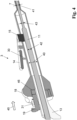
- Figure 4 shows a cross-section through an actuating device according to the invention to which the reference number 3 is assigned.
- the actuating device 3 comprises a connector 7, the distal end of which is connectable to a surgical instrument (not shown).
- Figure 4 illustrates the proximal end of the actuating device 3, in particular the locking section in which the wire 11 and the connector 7 are rotationally fixable to each other.
- wire 11 and connector 7 have larger diameter in the locking section compared to the puncturing section at the distal end of the hollow channel.
- the wire 11 is created by flattening.
- the maximum wire diameter in the locking section 42 is 6.5 mm; the maximum wire diameter in the puncturing section 43 is 1 mm.
- the inner diameter of the connector 7 in the locking section 40 is 8.5 mm, the inner diameter of the connector 7 in the puncturing section 41 is 1.4 mm.
- the connector 7 is made of surgical stainless steel; it has a wall thickness of 0.4 mm.
- the adjusting wheel 18 is connected to the connector 7; they are made of one piece. Thus, each rotation of the adjusting wheel 18 is associated with a rotation of the connector 7. Without special measures, the wire 11 and the connector 7 are rotatable relative to each other. Therefore, a rotation of the adjusting wheel 18 would lead to a rotation of the connector 7 relative to the wire 11. However, since both the wire 11 and the connector 7 are connected to the surgical instrument by rotation, a rotation of the connector 7 and the wire 11 relative to each other could result in loosening the connection of surgical instrument 2 and connector 7 or wire 11, respectively. Therefore, the actuating device 3 comprises a locking means 15 which is able to prevent the free rotation of wire 11 and connector 7 relative to each other.
- the locking means 15 is a cuboid with one rounded edge. It has a length of 35 mm, a width of 0.5 mm and a height of 6 mm; it can assume a closed position and an open position via lever 14.
- the lever 14 has a spring 30 that causes the locking means 15 to be held in the closed position. In the closed position, the locking means 15 protrudes in the hollow channel so deeply that it contacts one side of the flattened wire 11 such that it stops the rotation of the wire 7 in the first direction of rotation, opposite to the direction in which the wire 11 is connectable to the second mating coupling means of a surgical element.
- the handle 13 and the adjusting wheel 18 are mounted so that they can rotate relative to each other.
- this makes it difficult to connect the actuating device 3 with the surgical instrument 2, because in this case the connection between the actuating device 3 and the surgical instrument 2 can only be made by turning the adjusting wheel 18 which is a small component and therefore more difficult to operate. Therefore, the adjusting wheel 18 and the handle 13 are provided with a blocking means 19, with which the handle 13 and the adjusting wheel 18 can be firmly connected.
- the blocking means 19 is movable between a locking position in which adjusting wheel 18 and handle 13 are locked to each other and a non-locking position in which adjusting wheel 18 and handle 13 can freely rotate relative to each other.
- the blocking means 19 When the blocking means 19 is moved in the direction of arrow 45, it engages in an opening 46 of the adjusting wheel 18, thereby fixing handle 13 and adjusting wheel 18. Moving the blocking means 19 in the opposite direction to the direction of arrow 45 restores the relative movability of the adjusting wheel 18 and the handle 13.
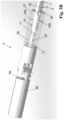
- FIG. 5 shows the proximal end of the actuating device 3 in detail.
- the actuating device 3 comprises a connector 7, a wire 11 guided in the hollow channel of the connector 7 and a handle 13.
- the connector 7 is equipped with an adjusting wheel 18 which is connected to the connector 7 in such a way that the adjusting wheel 18 can only be rotated along the connector longitudinal axis 8 together with the connector 7.
- the handle 13 is a separate part that can in principle rotate freely along the connector longitudinal axis 8 in relation to the connector 7 and the adjusting wheel 18.
- the actuating device 3 has a blocking mechanism with which the handle can be fixed to the adjusting wheel 18 and the connector 7, respectively.
- the adjusting wheel 18 has an opening in the form of a toothed rim 32 and the handle 13 has a locating channel 31 for a blocking means 19 in form of locating pin.
- the handle 13 and the adjusting wheel 18 fixed to each other so that the handle 13, the adjusting wheel 18 and the connector 7 can only be moved together.
- the connection between handle 13 and adjusting wheel 18 can be released by pulling the locking pin out of the toothed rim in the direction of the arrow 34.
- Figures 6A and 6B are a schematic illustration for explaining the operation of the connection between the actuating device 3 and the surgical instrument 2.
- Figure 6A shows a simplified cross-section through the locking section of the actuating device 3.
- Figure 6B depicts a simplified sectional view of the distal end of wire 11 and connector 7.
- Figures 6A and 6B have the same direction of view, namely towards the distal end of the connector 7.
- the method for connecting and disconnecting the surgical instrument and the actuating device is described below in more detail.
- the locking means 15 is in closed position.
Landscapes
- Health & Medical Sciences (AREA)
- Surgery (AREA)
- Life Sciences & Earth Sciences (AREA)
- Biomedical Technology (AREA)
- Nuclear Medicine, Radiotherapy & Molecular Imaging (AREA)
- Engineering & Computer Science (AREA)
- Ophthalmology & Optometry (AREA)
- Heart & Thoracic Surgery (AREA)
- Medical Informatics (AREA)
- Molecular Biology (AREA)
- Animal Behavior & Ethology (AREA)
- General Health & Medical Sciences (AREA)
- Public Health (AREA)
- Veterinary Medicine (AREA)
- Surgical Instruments (AREA)
Priority Applications (4)
| Application Number | Priority Date | Filing Date | Title |
|---|---|---|---|
| EP23163740.6A EP4434478A1 (fr) | 2023-03-23 | 2023-03-23 | Système chirurgical, dispositif d'actionnement pour actionner un instrument chirurgical et instrument chirurgical associé |
| CN202480018556.5A CN120916713A (zh) | 2023-03-23 | 2024-03-18 | 外科手术系统、用于致动外科手术器械的致动装置及外科手术器械 |
| PCT/EP2024/057132 WO2024194247A1 (fr) | 2023-03-23 | 2024-03-18 | Système chirurgical, dispositif d'actionnement d'instrument chirurgical, et instrument chirurgical associé |
| EP24711894.6A EP4683576A1 (fr) | 2023-03-23 | 2024-03-18 | Système chirurgical, dispositif d'actionnement d'instrument chirurgical, et instrument chirurgical associé |
Applications Claiming Priority (1)
| Application Number | Priority Date | Filing Date | Title |
|---|---|---|---|
| EP23163740.6A EP4434478A1 (fr) | 2023-03-23 | 2023-03-23 | Système chirurgical, dispositif d'actionnement pour actionner un instrument chirurgical et instrument chirurgical associé |
Publications (1)
| Publication Number | Publication Date |
|---|---|
| EP4434478A1 true EP4434478A1 (fr) | 2024-09-25 |
Family
ID=85726982
Family Applications (2)
| Application Number | Title | Priority Date | Filing Date |
|---|---|---|---|
| EP23163740.6A Withdrawn EP4434478A1 (fr) | 2023-03-23 | 2023-03-23 | Système chirurgical, dispositif d'actionnement pour actionner un instrument chirurgical et instrument chirurgical associé |
| EP24711894.6A Pending EP4683576A1 (fr) | 2023-03-23 | 2024-03-18 | Système chirurgical, dispositif d'actionnement d'instrument chirurgical, et instrument chirurgical associé |
Family Applications After (1)
| Application Number | Title | Priority Date | Filing Date |
|---|---|---|---|
| EP24711894.6A Pending EP4683576A1 (fr) | 2023-03-23 | 2024-03-18 | Système chirurgical, dispositif d'actionnement d'instrument chirurgical, et instrument chirurgical associé |
Country Status (3)
| Country | Link |
|---|---|
| EP (2) | EP4434478A1 (fr) |
| CN (1) | CN120916713A (fr) |
| WO (1) | WO2024194247A1 (fr) |
Citations (4)
| Publication number | Priority date | Publication date | Assignee | Title |
|---|---|---|---|---|
| WO2010114634A1 (fr) * | 2009-04-03 | 2010-10-07 | The Board Of Trustees Of The Leland Stanford Junior University | Dispositif et procédé chirurgicaux |
| WO2011153529A2 (fr) * | 2010-06-04 | 2011-12-08 | University Of South Florida | Instrument laparoscopique sans incision |
| US10835217B1 (en) * | 2014-12-18 | 2020-11-17 | New Wave Endo-Surgery Inc. | Assembly for doubly securing needlescopic instrument shafts to laparoscopic instrument heads |
| EP3777650A1 (fr) | 2018-03-28 | 2021-02-17 | Mao, Zhangfan | Système de chirurgie endoluminale |
-
2023
- 2023-03-23 EP EP23163740.6A patent/EP4434478A1/fr not_active Withdrawn
-
2024
- 2024-03-18 EP EP24711894.6A patent/EP4683576A1/fr active Pending
- 2024-03-18 CN CN202480018556.5A patent/CN120916713A/zh active Pending
- 2024-03-18 WO PCT/EP2024/057132 patent/WO2024194247A1/fr not_active Ceased
Patent Citations (4)
| Publication number | Priority date | Publication date | Assignee | Title |
|---|---|---|---|---|
| WO2010114634A1 (fr) * | 2009-04-03 | 2010-10-07 | The Board Of Trustees Of The Leland Stanford Junior University | Dispositif et procédé chirurgicaux |
| WO2011153529A2 (fr) * | 2010-06-04 | 2011-12-08 | University Of South Florida | Instrument laparoscopique sans incision |
| US10835217B1 (en) * | 2014-12-18 | 2020-11-17 | New Wave Endo-Surgery Inc. | Assembly for doubly securing needlescopic instrument shafts to laparoscopic instrument heads |
| EP3777650A1 (fr) | 2018-03-28 | 2021-02-17 | Mao, Zhangfan | Système de chirurgie endoluminale |
Also Published As
| Publication number | Publication date |
|---|---|
| WO2024194247A1 (fr) | 2024-09-26 |
| CN120916713A (zh) | 2025-11-07 |
| EP4683576A1 (fr) | 2026-01-28 |
Similar Documents
| Publication | Publication Date | Title |
|---|---|---|
| EP3946090B1 (fr) | Arbre d'entraînement de forceps | |
| US6051006A (en) | Suture-passing forceps | |
| US6162239A (en) | Instrument with independent pliers | |
| CA2157744C (fr) | Appareil endoscopique pour suture de tissu vasculaire | |
| US5690652A (en) | Surgical suturing device | |
| EP2400902B1 (fr) | Ciseaux chirurgicaux | |
| EP1300116A2 (fr) | Dispositif chirurgical de suture | |
| EP0140552A2 (fr) | Appareil jetable pour la pose de sutures linéaires à agrafes | |
| CA2486550A1 (fr) | Instruments de sutures | |
| EP3351192B1 (fr) | Instrument chirurgical, en particulier pour la neurochirurgie | |
| WO2014092863A1 (fr) | Système pour la réparation de tissus mous | |
| EP3106097B1 (fr) | Instrument de traitement | |
| CN110114002B (zh) | 腹腔镜装置 | |
| EP4434478A1 (fr) | Système chirurgical, dispositif d'actionnement pour actionner un instrument chirurgical et instrument chirurgical associé | |
| CN113164174A (zh) | 供给器、医疗设备以及医疗设备的安装方法 | |
| DE9203041U1 (de) | Laparoskopischer Nadelhalter | |
| US12544060B2 (en) | System, apparatus, and method for suturing | |
| EP2661230A2 (fr) | Système écarteur | |
| DE102022134137A1 (de) | Steuervorrichtung für eine endoskopische Vorrichtung, Handstück für eine flexible endoskopische Vorrichtung und endoskopische Vorrichtung | |
| WO2017212040A1 (fr) | Dispositif laparoscopique | |
| EP4609837A1 (fr) | Dispositif de transport et système de prothèse | |
| US20260114856A1 (en) | Releasable coupling for a medical device | |
| EP3784145B1 (fr) | Combinaison aiguille-suture, porte-aiguille et appareil de suture chirurgicale | |
| JPH09262242A (ja) | 持針器 | |
| CN119730798A (zh) | 缝合装置 |
Legal Events
| Date | Code | Title | Description |
|---|---|---|---|
| PUAI | Public reference made under article 153(3) epc to a published international application that has entered the european phase |
Free format text: ORIGINAL CODE: 0009012 |
|
| STAA | Information on the status of an ep patent application or granted ep patent |
Free format text: STATUS: THE APPLICATION HAS BEEN PUBLISHED |
|
| AK | Designated contracting states |
Kind code of ref document: A1 Designated state(s): AL AT BE BG CH CY CZ DE DK EE ES FI FR GB GR HR HU IE IS IT LI LT LU LV MC ME MK MT NL NO PL PT RO RS SE SI SK SM TR |
|
| STAA | Information on the status of an ep patent application or granted ep patent |
Free format text: STATUS: THE APPLICATION IS DEEMED TO BE WITHDRAWN |
|
| 18D | Application deemed to be withdrawn |
Effective date: 20250326 |