EP3778281A1 - Ensemble roue électrique à moteur de moyeu intégré - Google Patents
Ensemble roue électrique à moteur de moyeu intégré Download PDFInfo
- Publication number
- EP3778281A1 EP3778281A1 EP18914531.1A EP18914531A EP3778281A1 EP 3778281 A1 EP3778281 A1 EP 3778281A1 EP 18914531 A EP18914531 A EP 18914531A EP 3778281 A1 EP3778281 A1 EP 3778281A1
- Authority
- EP
- European Patent Office
- Prior art keywords
- motor
- gear
- knuckle
- spoke plate
- wheel assembly
- Prior art date
- Legal status (The legal status is an assumption and is not a legal conclusion. Google has not performed a legal analysis and makes no representation as to the accuracy of the status listed.)
- Granted
Links
Images

Classifications
-
- B—PERFORMING OPERATIONS; TRANSPORTING
- B60—VEHICLES IN GENERAL
- B60K—ARRANGEMENT OR MOUNTING OF PROPULSION UNITS OR OF TRANSMISSIONS IN VEHICLES; ARRANGEMENT OR MOUNTING OF PLURAL DIVERSE PRIME-MOVERS IN VEHICLES; AUXILIARY DRIVES FOR VEHICLES; INSTRUMENTATION OR DASHBOARDS FOR VEHICLES; ARRANGEMENTS IN CONNECTION WITH COOLING, AIR INTAKE, GAS EXHAUST OR FUEL SUPPLY OF PROPULSION UNITS IN VEHICLES
- B60K7/00—Disposition of motor in, or adjacent to, traction wheel
- B60K7/0007—Disposition of motor in, or adjacent to, traction wheel the motor being electric
-
- B—PERFORMING OPERATIONS; TRANSPORTING
- B60—VEHICLES IN GENERAL
- B60K—ARRANGEMENT OR MOUNTING OF PROPULSION UNITS OR OF TRANSMISSIONS IN VEHICLES; ARRANGEMENT OR MOUNTING OF PLURAL DIVERSE PRIME-MOVERS IN VEHICLES; AUXILIARY DRIVES FOR VEHICLES; INSTRUMENTATION OR DASHBOARDS FOR VEHICLES; ARRANGEMENTS IN CONNECTION WITH COOLING, AIR INTAKE, GAS EXHAUST OR FUEL SUPPLY OF PROPULSION UNITS IN VEHICLES
- B60K17/00—Arrangement or mounting of transmissions in vehicles
- B60K17/04—Arrangement or mounting of transmissions in vehicles characterised by arrangement, location or kind of gearing
- B60K17/043—Transmission unit disposed in on near the vehicle wheel, or between the differential gear unit and the wheel
- B60K17/046—Transmission unit disposed in on near the vehicle wheel, or between the differential gear unit and the wheel with planetary gearing having orbital motion
-
- B—PERFORMING OPERATIONS; TRANSPORTING
- B60—VEHICLES IN GENERAL
- B60K—ARRANGEMENT OR MOUNTING OF PROPULSION UNITS OR OF TRANSMISSIONS IN VEHICLES; ARRANGEMENT OR MOUNTING OF PLURAL DIVERSE PRIME-MOVERS IN VEHICLES; AUXILIARY DRIVES FOR VEHICLES; INSTRUMENTATION OR DASHBOARDS FOR VEHICLES; ARRANGEMENTS IN CONNECTION WITH COOLING, AIR INTAKE, GAS EXHAUST OR FUEL SUPPLY OF PROPULSION UNITS IN VEHICLES
- B60K17/00—Arrangement or mounting of transmissions in vehicles
- B60K17/04—Arrangement or mounting of transmissions in vehicles characterised by arrangement, location or kind of gearing
- B60K17/12—Arrangement or mounting of transmissions in vehicles characterised by arrangement, location or kind of gearing of electric gearing
-
- B—PERFORMING OPERATIONS; TRANSPORTING
- B60—VEHICLES IN GENERAL
- B60L—PROPULSION OF ELECTRICALLY-PROPELLED VEHICLES; SUPPLYING ELECTRIC POWER FOR AUXILIARY EQUIPMENT OF ELECTRICALLY-PROPELLED VEHICLES; ELECTRODYNAMIC BRAKE SYSTEMS FOR VEHICLES IN GENERAL; MAGNETIC SUSPENSION OR LEVITATION FOR VEHICLES; MONITORING OPERATING VARIABLES OF ELECTRICALLY-PROPELLED VEHICLES; ELECTRIC SAFETY DEVICES FOR ELECTRICALLY-PROPELLED VEHICLES
- B60L7/00—Electrodynamic brake systems for vehicles in general
- B60L7/10—Dynamic electric regenerative braking
-
- B—PERFORMING OPERATIONS; TRANSPORTING
- B60—VEHICLES IN GENERAL
- B60T—VEHICLE BRAKE CONTROL SYSTEMS OR PARTS THEREOF; BRAKE CONTROL SYSTEMS OR PARTS THEREOF, IN GENERAL; ARRANGEMENT OF BRAKING ELEMENTS ON VEHICLES IN GENERAL; PORTABLE DEVICES FOR PREVENTING UNWANTED MOVEMENT OF VEHICLES; VEHICLE MODIFICATIONS TO FACILITATE COOLING OF BRAKES
- B60T1/00—Arrangements of braking elements, i.e. of those parts where braking effect occurs specially for vehicles
- B60T1/02—Arrangements of braking elements, i.e. of those parts where braking effect occurs specially for vehicles acting by retarding wheels
- B60T1/06—Arrangements of braking elements, i.e. of those parts where braking effect occurs specially for vehicles acting by retarding wheels acting otherwise than on tread, e.g. employing rim, drum, disc, or transmission or on double wheels
- B60T1/062—Arrangements of braking elements, i.e. of those parts where braking effect occurs specially for vehicles acting by retarding wheels acting otherwise than on tread, e.g. employing rim, drum, disc, or transmission or on double wheels acting on transmission parts
-
- B—PERFORMING OPERATIONS; TRANSPORTING
- B60—VEHICLES IN GENERAL
- B60B—VEHICLE WHEELS; CASTORS; AXLES FOR WHEELS OR CASTORS; INCREASING WHEEL ADHESION
- B60B27/00—Hubs
- B60B27/0047—Hubs characterised by functional integration of other elements
- B60B27/0052—Hubs characterised by functional integration of other elements the element being a brake disc
-
- B—PERFORMING OPERATIONS; TRANSPORTING
- B60—VEHICLES IN GENERAL
- B60K—ARRANGEMENT OR MOUNTING OF PROPULSION UNITS OR OF TRANSMISSIONS IN VEHICLES; ARRANGEMENT OR MOUNTING OF PLURAL DIVERSE PRIME-MOVERS IN VEHICLES; AUXILIARY DRIVES FOR VEHICLES; INSTRUMENTATION OR DASHBOARDS FOR VEHICLES; ARRANGEMENTS IN CONNECTION WITH COOLING, AIR INTAKE, GAS EXHAUST OR FUEL SUPPLY OF PROPULSION UNITS IN VEHICLES
- B60K7/00—Disposition of motor in, or adjacent to, traction wheel
- B60K2007/0038—Disposition of motor in, or adjacent to, traction wheel the motor moving together with the wheel axle
-
- B—PERFORMING OPERATIONS; TRANSPORTING
- B60—VEHICLES IN GENERAL
- B60K—ARRANGEMENT OR MOUNTING OF PROPULSION UNITS OR OF TRANSMISSIONS IN VEHICLES; ARRANGEMENT OR MOUNTING OF PLURAL DIVERSE PRIME-MOVERS IN VEHICLES; AUXILIARY DRIVES FOR VEHICLES; INSTRUMENTATION OR DASHBOARDS FOR VEHICLES; ARRANGEMENTS IN CONNECTION WITH COOLING, AIR INTAKE, GAS EXHAUST OR FUEL SUPPLY OF PROPULSION UNITS IN VEHICLES
- B60K7/00—Disposition of motor in, or adjacent to, traction wheel
- B60K2007/0092—Disposition of motor in, or adjacent to, traction wheel the motor axle being coaxial to the wheel axle
-
- B—PERFORMING OPERATIONS; TRANSPORTING
- B60—VEHICLES IN GENERAL
- B60Y—INDEXING SCHEME RELATING TO ASPECTS CROSS-CUTTING VEHICLE TECHNOLOGY
- B60Y2410/00—Constructional features of vehicle sub-units
- B60Y2410/102—Shaft arrangements; Shaft supports, e.g. bearings
Definitions
- the present disclosure relates to a technical field of new energy vehicles, more particularly to an electric wheel assembly with integrated hub motor and reducer.
- the distributed-electric-drive configuration can be employed to avoid the above restrictions effectively.
- the electric wheel driven by hub motors can be employed so that the chasis' usable space can be greatly saved, and the components other than the driving system can be easily and flexibly arranged.
- the electric wheel's design itself becomes more difficult. How to reasonably arrange the drive motor, the reduction mechanism, the brake element, and connect the suspension and steering system within the wheel's limited space become the research focus of various automobile companies and research institutes.
- the present disclosure seeks to solve at least one of the problems existing in the related art. To this end, the present disclosure proposes an electric wheel assembly with an integrated hub motor, and various components of the electric wheel assembly have reasonable load and light mass.
- the electric wheel assembly with the integrated hub motor includes: a rim adapted to mount a tire and having a spoke plate at an axial end of the rim; a hub connected to the spoke plate; a steering knuckle assembly including a knuckle sleeve, the knuckle sleeve being fitted over a shaft section of the hub, the knuckle and the hub being provided with a hub bearing therebetween; an inner rotor motor provided inside the rim and including: a motor housing including a motor rotor holder fitted over an outside of the knuckle sleeve, a rotor having a hollow structure, fitted over and secured on the motor rotor holder, and a stator fitted in and secured on the motor housing, the stator being fitted over an outside of the rotor; a planetary reducer including: a sun gear connected to an end of the motor rotor holder close to the spoke plate and being an input end of the planetary reducer
- the inner rotor motor is a radial field motor, or a radial-axial hybrid-field motor.
- the motor housing further includes: a motor stator housing fitted over the stator; a motor inner end cap connected to a side of the motor stator housing away from the spoke plate and connected to the steering knuckle assembly; and a motor outer end cap connected to a side of the motor stator housing close to the spoke plate.
- the motor outer end cap and the motor rotor holder are provided with a motor bearing therebetween, and the motor inner end cap and the motor rotor holder are provided with a motor bearing therebetween.
- the sun gear is mounted to an end of the motor rotor holder close to the spoke plate, and an end of the motor rotor holder away from the spoke plate is connected to the brake disc of the braking system through the brake disc connection sleeve.
- the planetary reducer is a one-stage planetary reducer, and the planetary reducer further includes: a planet carrier disc mounted to an end of the planet carrier away from the spoke plate; a plurality of planet gears, each planet gear being mounted between the planet carrier and the planet carrier disc through a planet gear pin and meshing with the sun gear to transmit power output by the inner rotor motor; a gear ring fitted over the planet gears and meshing with the planet gears; and a gear ring carrier fitted over the gear ring, an end of the gear ring carrier being connected to the motor stator housing and the motor outer end cap, the gear ring carrier being formed as a stepped sleeve gradually expanded in a direction away from the spoke plate, and a peripheral face of the gear ring carrier is provided with a reinforcing rib.
- each planet gear employs a tower-shaped gear structure including: a primary gear meshing with the sun gear; and a secondary gear disposed coaxially with the primary gear and meshing with the gear ring, the number of teeth on the secondary gear is less than the number of teeth on the primary gear.
- the planet carrier is provided with a through hole fitted with the planet gear pin, an end of the planet gear pin passes through the planet carrier and the spoke plate and is locked on the spoke plate though a nut and a connection member, the other end of the planet gear pin passes through the planet carrier disc and is positioned on the planet carrier disc through a shaft retaining ring, and the planet gear pin is provided with a lubrication oil channel.
- the planetary reducer further includes a toque transferring pin, an end of the toque transferring pin passes through the planet carrier disc and is positioned on the planet carrier disc through a shaft retaining ring, and the other end of the toque transferring pin is connected to the planet carrier.
- the planetary reducer further includes a gear ring end cap connected to an end of the gear ring carrier close to the spoke plate, the gear ring end cap is fitted over an outside of the planet carrier, the gear ring end cap, the gear ring, the gear ring carrier and the planet carrier defines a gap thereamong, the gap is provided with a reducer oil seal therein, and the reducer oil seal is locked on the gear end cap through a screw.
- the motor inner end cap is provided with a lubrication oil inlet
- the motor outer end cap is provided with a lubrication oil outlet
- the lubrication oil outlet is open to an interior of the planetary reducer.
- the motor rotor holder and the motor inner end cap are provided with a motor oil seal therebetween, the motor oil seal is located at a side of the motor bearing away from the spoke plate, an inner peripheral wall of the motor rotor holder or an outer peripheral wall of the knuckle sleeve is provided with an oil seal groove, the oil seal groove is provided with a knuckle oil seal therein, and the knuckle oil seal is fitted over the knuckle sleeve.
- an end of the hub away from the spoke plate is mounted with a round nut, and an end of the round nut abuts against an end face of the hub bearing away from the spoke plate.
- the steering knuckle assembly further includes: a knuckle mounted to an end of the knuckle sleeve away from the spoke plate, the knuckle being provided with a mounting opening for a suspension swing arm, a steering knuckle arm or a steering tie rod; a steering knuckle connection cover, an end of the steering knuckle connection cover away from the spoke plate being connected to the knuckle, and the other end thereof is provided with a flange for supporting the motor housing; and a sealing end cap snapped into a side of the knuckle sleeve away from the spoke plate and provided with an oil return hole for backflow of the lubrication oil.
- the braking system further includes a brake caliper connected to the steering knuckle connection cover of the steering knuckle assembly.
- the braking system is a disc mechanical braking system with variable pneumatic pressure or variable hydraulic pressure
- the electric wheel assembly is able to employ a form of electromechanical hybrid brake
- the inner rotor motor is able to provide a braking toque, and operate synergistically with the disc braking system with variable pneumatic pressure or variable hydraulic pressure.
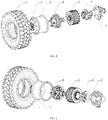
- the electric wheel assembly 100 includes a tire 1, a rim 3, a hub 16, a planetary reducer 4, an inner rotor motor 5, a braking system 6 and a steering knuckle assembly 7.
- the rim 3 is adapted to mount the tire 1, an axial end of the rim 3 has a spoke plate 2, and the hub 16 is connected to the spoke plate 2.
- the steering knuckle assembly 7 includes a knuckle sleeve 17.
- the knuckle sleeve 17 is fitted over a shaft segment of the hub 16, and hub bearings 24 are provided between the knuckle sleeve 17 and the hub 16.
- the inner rotor motor 5 is provided in the rim 3.
- the inner rotor motor 5 includes a motor housing 41, a rotor 34 and a stator 33.
- the motor housing 41 includes a motor rotor holder 36 fitted over an outside of the knuckle sleeve 17 and a motor stator housing 31 located at the radially outermost periphery of the inner rotor motor 5.
- the rotor 34 is fitted over and secured on the motor rotor holder 36, the stator 33 is fitted in and secured on the motor stator housing 31, and the stator 33 is fitted over an outside of the rotor 34.
- the rotor 34 has a hollow structure such that the knuckle sleeve 17 and the shaft segment of the hub 16 can be arranged.
- the planetary reducer 4 includes a sun gear 15 and a planet carrier integrated with the hub 16.
- the sun gear 15 is connected to an end of the motor rotor holder 36 close to the spoke plate 2 and serves as an input end of the planetary reducer 4, and the planet carrier serves as an output end of the planetary reducer 4.
- the braking system 6 includes a brake disc 21.
- the brake disc 21 is fitted over the motor rotor holder 36 through a brake disc connection sleeve 20 and located at an end of the rotor 34 sleeve away from the spoke plate 2.
- the braking system 6 brakes the electric wheel assembly 100 by braking the motor rotor holder 36.
- the inner rotor motor 5 has a hollow structure
- the knuckle sleeve 17 of the steering knuckle assembly 7 passes through the hollow motor rotor holder 36
- a motor bearing 39 is provided between the motor rotor holder 36 and a fixed portion of the motor housing 41
- hub bearings 24 are provided between the knuckle sleeve 17 and the hub 16
- the motor bearing 39 is provided at a radially outside of the hub bearing 24.
- a force-bearing center of the electric wheel assembly 100 is closer to a wheel center of the tire 1 to ensure a bearing span of the hub bearings 24.
- the radial space in the wheel is fully used to facilitate reduction in the axial size of the electric wheel assembly 100, thereby reducing the overall size of the electric wheel assembly 100.
- the braking system 6 brakes the electric wheel assembly 100 by braking the brake disc connection sleeve 20, the rotor holder 36 and the planetary reducer 4, compared to conventional solutions of braking the rim 3, the braking system 6 according to embodiments of the present disclosure, which is disposed at a high speed end, can reduce the brake force of the braking system 6, therefore, the braking system 6 can be designed to be lighter, greatly reducing the mass of the electric wheel assembly 100.
- the inner rotor motor 5 is a radial field motor, or a radial-axial hybrid-field motor.
- longitudinal sections of the rotor 34 and the stator 33 are both formed as saddle shapes. It could be understood that, the saddle-shaped section make the magnetic field of the motor have both axial and radial components, and the advantages of this arrangement are that the torque density and the power density of the motor can be effectively improved.
- the motor housing 41 further includes a motor inner end cap 30 and a motor outer end cap 37.
- the motor inner end cap 30 is connected to a side of the motor stator housing 31 away from the spoke plate 2, and the motor inner end cap 30 is connected to the steering knuckle assembly 7.
- the motor outer end cap 37 is connected to a side of the motor stator housing 31 close to the spoke plate 2.
- the motor outer end cap 37 and the motor rotor holder 36 are provided with a motor bearing 39 therebetween, and the motor inner end cap 30 and the motor rotor holder 36 are provided with a motor bearing 39 therebetween. It could be understood that the motor housing 41 has functions of bearing, fixing, and protecting the inner rotor motor 5.
- the motor stator housing 31 may also be arranged with a cooling channel.
- the motor rotor holder 36 may also transfer an output torque of the motor.
- the motor outer end cap 37 and the motor inner end cap 30 may be arranged with a bearing positioning face, to limit axial displacement of the motor bearings 39.
- the motor bearings 39 are deep groove ball bearings, and the hub bearings 24 are tapered roller bearings.
- the types of the motor bearing 39 and the hub bearing 24 are not limited to the above two types, and the types of the motor bearing 39 and the hub bearing 24 can be changed according to specific conditions in practice.
- the motor rotor holder 36 and the motor inner end cap 30 are provided with a motor oil seal 27 therebetween, the motor oil seal 27 is located at a side of the motor bearing 39 away from the spoke plate 2, and a motor oil seal retaining ring 26 may also be provided among a side of the motor oil seal 27 away from the spoke plate 2, the motor inner end cap 31 and the motor rotor holder 36.
- An oil seal groove is provided between the motor rotor holder 36 or the knuckle sleeve 17, e.g. in an inner peripheral wall of the motor rotor holder 36 or in an outer peripheral wall of the knuckle sleeve 17.
- the oil seal groove is provided with a knuckle oil seal 35 therein, and the knuckle oil seal 35 is fitted over the knuckle sleeve 17.
- the lubrication oil can be prevented from leakage from a direction of the motor inner end cap 30.
- the knuckle oil seal 35 may be a split oil seal.
- a resolver 29 is arranged between the motor bearing 39 away from the spoke plate 2 and the motor oil seal 27. It should be noted that, axial positions of the resolver 29 and the motor oil seal 27 may be exchanged according to practical conditions. That is, the motor oil seal 27 is arranged between the resolver 29 and the motor bearing 39 away from the spoke plate 2.
- the sun gear 15 is mounted to an end of the motor rotor holder 36 close to the spoke plate 2, and an end of the motor rotor holder 36 away from the spoke plate 2 is connected to the brake disc 21 of the braking system 6 through the brake disc 21 connection sleeve 20.
- connection manner of the motor rotor holder 36 and the sun gear 15 is not limited to the above-described one.
- the sun gear 15 may also be axially secured to the motor rotor holder 36 by bolts, or a combination of bolts and bearing pins, or mounted to the motor rotor holder 36 by way of interference fit.
- the sun gear 15 and the motor rotor holder 36 may also be integrally processed into one piece.
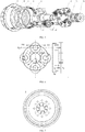
- the planetary reducer 4 is a one-stage planetary reducer 4.
- the planetary reducer 4 further includes a planet carrier disc 14, planet gears 13, a planet gear pin 11, a gear ring 10 and a gear ring carrier 9.
- the planet carrier of the planetary reducer 4 and the hub are integrated into one piece, and the planet carrier disc 14 is mounted to an end of planet carrier away from spoke plate 2.
- a plurality of planet gears 13 is provided, each planet gear 13 is mounted between the planet carrier and the planet carrier disc 14 through the planet gear pin 11, and each planet gear 13 meshes with the sun gear 15 to transfer power from the inner rotor motor 5.
- the gear ring 10 is fitted over the planet gears 13 and meshes with the planet gears 13, and the gear ring carrier 9 is fitted over the gear ring 10.
- An end of the gear ring carrier 9 away from the spoke plate 2 is connected to the motor stator housing 31 and the motor outer end cap 37, the gear ring carrier 9 is formed as a stepped sleeve gradually expanded in a direction away from the spoke plate 2, and a peripheral face of the gear ring carrier 9 is provided with a reinforcing rib.
- each planet gear 13 employs a tower-shaped gear structure including: a primary gear meshing with the sun gear 15; and a secondary gear disposed coaxially with the primary gear and meshing with the gear ring 10.
- the number of teeth on the secondary gear is less than the number of teeth on the primary gear.
- the number of teeth on the sun gear 15 is denoted as z1
- the number of teeth on primary gear of the planet gear 13 is denoted as z2
- the number of teeth on the secondary gear is denoted as z3
- the number of teeth on the gear ring 10 is denoted as z4.
- the primary stage employs a form of tower-shaped gear, such that an effect similar to a two-stage planetary reducer can be obtained, while ensuring an adequate transmission ratio.
- the axial length of the planetary reducer 4 can be effectively reduced, to make the position of the hub bearing 24 wholly closer to the wheel center and make the support span greater.
- the planetary reducer 4 designed in this way also has a lighter mass. It needs to be added that, the primary gear and the secondary gear may be manufactured integrally, and may also be manufactured separately and then connected on the same axis by interference or other connection ways.
- the hub 16 integrated with the planet carrier is not only the hub 16 of the electric wheel assembly 100, but also the planet carrier of the planetary reducer 4.
- the planet carrier is connected to the spoke plate 2.
- the planet carrier is provided with through holes fitted with the planet gear pin 11, an end of the planet gear pin 11 passes through the planet carrier, the spoke plate 2 and is locked on the spoke plate 2 through a nut and connection keys, and the other end of the planet gear pin 11 passes through the planet carrier disc 14 and is positioned on the planet carrier disc 14 through a shaft retaining ring.
- the planet gear pin 11 is provided with lubrication oil channels. It could be understood that, the planet carrier disc 14, the planet carrier and the spoke plate 2 are connected by the planet gear pin 11, and the planet gear pin 11 is provided with the lubrication oil channels.
- a pin hole in the spoke plate 2 for mounting the planet gear pin 11 is provided with key slots.
- movement of the planet gear pin 11 can be further constrained, and the rotation of the planet gear pin 11 can be constrained during screwing the nut, which is convenient for facilitating the assembly.
- the planetary reducer 4 further includes a toque transferring pin 42, an end of the toque transferring pin 42 passes through the planet carrier disc 14 and is positioned on the planet carrier disc 14 through a shaft retaining ring, and the other end of the toque transferring pin 42 is connected to the planet carrier.
- a toque transferring pin 42 there are several protruding structures of boss shape in the space between the planet gears 13 placed on the planet carrier.
- the number of the protruding structures is the same as the number of the planet gears 13, and the protruding structure has a hole that allows the toque transferring pin 42 to pass through.
- the planetary reducer 4 further includes a gear ring end cap 38.
- the gear ring end cap 38 is mounted to an end of the gear ring carrier 9 close to the spoke plate 2, the gear ring end cap 38 is fitted over an outside of the planet carrier.
- the gear ring end cap 38, the gear ring 10, the gear ring carrier 9 and the planet carrier defines a gap thereamong.
- the gap is provided with a reducer oil seal 8 therein, and the reducer oil seal 8 is locked on the gear ring end cap 38 through a screw.
- the gear ring 10 and the gear ring carrier 9 are connected by an interference fit.
- the motor inner end cap 30 is provided with a lubrication oil inlet
- the motor outer end cap 37 is provided with a lubrication oil outlet
- the lubrication oil outlet is open to an interior of the planetary reducer 4.
- the present inventive electric wheel assembly 100 employs an integrated cooling method, that is, the inner rotor motor 5 is directly cooled by oil and shares common oil paths with the planetary reducer 4. That is to say, the motor cooling/lubrication oil of high insulation (short for lubrication oil in the following) serves as the lubrication oil for the planetary reducer 4 at the same time to lubricate and cool the planetary reducer 4.
- An oil pump, an oil radiator and a filter are provided on a vehicle body, so that the lubrication oil after cooled and filtered is pumped into the inner rotor motor 5 via the lubrication oil inlet in the motor inner end cap 30, passes through the stator 33 and the winding 32, and flows into a cavity of the planetary reducer 4 via the lubrication oil outlet in the motor outer end cap 37 to lubricate and cool it.
- the lubrication oil flows from the sun gear 15 to the hub bearing 24, and enters an internal space of the steering knuckle assembly 7.
- the lubrication oil flows to the filter and the radiator through an oil return opening in the steering knuckle assembly 7.
- the integrated cooling and lubricating method is employed, such that the overall structure of the electric wheel assembly 100 is more compact.
- the inner rotor motor 5 is directly cooled by the oil, and a water jacket of the inner rotor motor 5 can be omitted, to reduce radial size of the inner rotor motor 5.
- the stator 33 and the winding 32 of the inner rotor motor 5 are wholly cooled, the cooling effect on the inner rotor motor 5 can be improved, the lubrication state and the reliability of the planetary reducer 4 can be promoted, and the planetary reducer 4 can also be cooled.
- the inner rotor motor 5 and the planetary reducer 4 need to be lubricated and cooled separately.
- no lubrication oil outlet is provided in the motor outer end cap 37 of the inner rotor motor 5, and an oil seal and an oil slinger 40 are provided between the motor outer end cap 37 and the housing of the reducer to prevent the motor lubrication oil from entering the planetary reducer 4.
- an end of the hub 16 away from the spoke plate 2 is mounted with a round nut 26, and an end of the round nut 26 abuts against an end face of the hub bearing 24 away from the spoke plate 2. It could be understood that, the round nut 26 can avoid occurrence of axial displacement of the hub bearing 24.
- the steering knuckle assembly 7 further includes a knuckle 22, a steering knuckle connection cover 18 and a sealing end cap 25.
- the knuckle 22 is mounted to an end of the spoke plate 2 of the knuckle sleeve 17, and the knuckle 22 may be provided with a mounting opening for a suspension swing arm, a steering knuckle arm, or a steering tie rod.
- An end of the steering knuckle connection cover 18 away from the spoke plate 2 is connected to the knuckle 22, and an end thereof close to the spoke plate 2 is provided with a flange for supporting the motor housing 41.
- the sealing end cap 25 is snapped into a side of the knuckle 22 away from the spoke plate 2, and the sealing end cap 25 is provided with an oil return hole for backflow of the lubrication oil.
- a side of the knuckle 22 has mounting holes for a brake caliper 23, a motor mounting flange face of the other side thereof also has an aperture to arrange a coolant inlet, an interface of motor three-phase cables, and an interface of a low-voltage signal (such as a motor resolver 29 signal and a temperature sensor signal) cable.
- the steering knuckle assembly 7 is used to realize the support for the electric wheel assembly 100, is mounted with structures of a suspension spherical hinge 19 and the steering knuckle arm or the similar structures to connect the suspension and the steering linkage of the vehicle, and also provides a mounting plane for the inner rotor motor 5.
- the sealing end cap 25 can avoid leakage of the lubrication oil in the knuckle sleeve 17.
- the steering knuckle assembly 7 is not limited to a manufacturing method of separate processing, and can employ a manufacturing method of integrated processing, in which the knuckle 22, the knuckle sleeve 17 and the steering knuckle connection cover 18 are integrally processed into one piece.
- the braking system 6 further includes a brake caliper 23, and the brake caliper 23 is connected to the steering knuckle connection cover 18 of the steering knuckle assembly 7. It could be understood that, the mounting way of the brake disc 21 being directly mounted to the motor rotor holder 36 through the brake disc connection sleeve 20 reduces the required brake torque by the braking system 6, and thus helps to reduce the size of the brake caliper 23, thereby reducing the mass of the braking system 6.
- the brake disc 21 connection sleeve 20 is made of ceramic material of good thermal insulation effect, thereby effectively reducing influence of the heat from the brake disc 21 on the inner rotor motor 5 and guaranteeing good operation of the inner rotor motor 5.
- two ends of the steering knuckle connection cover 18 is connected by a grid cylinder, and a head wind can be introduced into the brake disc 21 to ensure effective cooling for the brake disc 21 during driving.
- the braking system 6 may be a disc mechanical braking system with variable pneumatic or hydraulic pressure.
- the electric wheel assembly 100 employs a form of electromechanical hybrid brake, and when the electric wheel assembly is in a braking operation mode, the inner rotor motor 5 can provide a braking toque, and operates synergistically with the disc braking system 6 with variable pneumatic or hydraulic pressure.
- the electric wheel assembly 100 with the integrated hub 16 motor of the present embodiment includes a tire 1, a rim 3, a hub 16, a planetary reducer 4, an inner rotor motor 5, a braking system 6 and a steering knuckle assembly 7.
- the rim 3 is adapted to mount the tire 1, an axial end of the rim 3 has a spoke plate 2, and the hub 16 is connected to the spoke plate 2.
- the steering knuckle assembly 7 includes a knuckle sleeve 17.
- the steering knuckle assembly 17 is fitted over a shaft segment of the hub 16, and hub bearings 24 are provided between the knuckle sleeve 17 and the hub 16.
- the inner rotor motor 5 is provided in the rim 3.
- the inner rotor motor 5 includes a motor housing 41, a rotor 34 and a stator 33.
- the motor housing 41 includes a motor rotor holder 36 fitted over an outside of the knuckle sleeve 17 and a motor stator housing 31 located at the radially outermost periphery of the inner rotor motor 5.
- the rotor 34 is fitted over and secured on the motor rotor holder 36, the stator 33 is fitted in and secured on the motor stator housing 31, and the stator 33 is fitted over an outside of the rotor 34.
- the rotor 34 has a hollow structure such that the knuckle sleeve 17 and the shaft segment of the hub 16 can be arranged.
- the planetary reducer 4 includes a sun gear 15 and a planet carrier integrated with the hub 16.
- the sun gear 15 is connected to an end of the motor rotor holder 36 close to the spoke plate 2 and serves as an input end of the planetary reducer 4, and the planet carrier serves as an output end of the planetary reducer 4.
- the braking system 6 includes a brake disc 21.
- the brake disc 21 is fitted over the motor rotor holder 36 through a brake disc connection sleeve 20 and located at an end of the rotor 34 sleeve away from the spoke plate 2.
- the braking system 6 brakes the electric wheel assembly 100 by braking the motor rotor holder 36.
- the motor housing 41 further includes a motor inner end cap 30 and a motor outer end cap 37.
- the motor inner end cap 30 is connected to a side of the motor stator housing 31 away from the spoke plate 2, and the motor inner end cap 30 is connected to the steering knuckle assembly 7.
- the motor outer end cap 37 is connected to a side of the stator housing 31 close to the spoke plate 2.
- the motor outer end cap 37 and the motor rotor holder 36 are provided with a motor bearing 39 therebetween, and the motor inner end cap 30 and the motor rotor holder 36 are provided with a motor bearing 39 therebetween.
- the motor rotor holder 36 and the motor inner end cap 30 are provided with a motor oil seal 27 therebetween, the motor oil seal 27 is located at a side of the motor bearing 39 away from the spoke plate 2, and a motor oil seal retaining ring 26 may also be provided among a side of the motor oil seal 27 away from the spoke plate 2, the motor inner end cap 31 and the motor rotor holder 36.
- a resolver 29 is arranged between the motor bearing 39 away from the spoke plate 2 and the motor oil seal 27.
- the sides of the two motor bearings 39 close to the rotor 34 are further provided with an oil slinger 40 fitted over the motor rotor holder 36.
- An oil seal groove is provided in the motor rotor holder 36 or the knuckle sleeve 17, e.g.
- the oil seal groove is provided with a knuckle oil seal 35 therein, and the knuckle oil seal 35 is fitted over the knuckle sleeve 17.
- the planetary reducer 4 is a one-stage planetary reducer 4.
- the planetary reducer 4 further includes a planet gear 13, a planet gear pin 11, a planet carrier disc 14, a gear ring 10 and a gear ring carrier 9.
- the planet carrier disc 14 is mounted to an end of planet carrier away from spoke plate 2.
- Four planet gears 13 are provided, each planet gear 13 is mounted between the planet carrier and the planet carrier disc 14 through the planet gear pin 11, and each planet gear 13 meshes with the sun gear 15 to transfer power input from the inner rotor motor 5.
- the gear ring 10 is fitted over the planet gear 13 and meshes with the planet gear 13, and the gear ring carrier 9 is fitted over the gear ring 10.
- gear ring carrier 9 An end of the gear ring carrier 9 away from the spoke plate 2 is connected to the motor stator housing 31 and the motor outer end cap 37, the gear ring carrier 9 is formed as a stepped sleeve gradually expanded in a direction away from the spoke plate 2, and a peripheral face of the gear ring carrier 9 is provided with a reinforcing rib.
- Each planet gear 13 employs a tower-shaped gear structure including: a primary gear meshing with the sun gear 15; and a secondary gear disposed coaxially with the primary gear and meshing with the gear ring 10.
- the number of teeth on the secondary gear is less than the number of teeth on the primary gear.
- the hub 16 integrated with the planet carrier is not only the hub 16 of the electric wheel assembly 100, but also the planet carrier of the planetary reducer 4.
- the planet carrier is connected to the spoke plate 2.
- the planet carrier is provided with through holes fitted with the planet gear pin 11, an end of the planet gear pin 11 passes through the planet carrier, the spoke plate 2 and is locked on the spoke plate 2 through a nut and connection keys, and the other end of the planet gear pin 11 passes through the planet carrier disc 14 and is positioned on the planet carrier disc 14 through a shaft retaining ring.
- the planet gear pin 11 defines a lubrication oil channel.
- the pin hole on the spoke plate 2 for mounting the planet gear pin 11 is provided with a key slot.
- the planetary reducer 4 further includes a toque transferring pin 42, an end of the toque transferring pin 42 passes through the planet carrier disc 14 and is positioned on the planet carrier disc 14 through a shaft retaining ring, and the other end of the toque transferring pin 42 is connected to the planet carrier.
- a toque transferring pin 42 there are four protruding structures of boss shape in the space among the planet gears 13 placed on the planet carrier, the number of the protruding structures is the same as the number of the planet gears 13, and the protruding structure has a hole that allows the toque transferring pin 42 to pass through.
- the planetary reducer 4 further includes a gear ring end cap 38.
- the gear ring end cap 38 is mounted to an end of the gear ring carrier 9 close to the spoke plate 2, the gear ring end cap 38 is fitted over an outside of the planet carrier, the gear ring end cap 38, the gear ring 10, the gear ring carrier 9 and the planet carrier defines a gap thereamong, the gap is provided with a reducer oil seal 8 therein, and the reducer oil seal 8 is locked on the gear ring end cap 38 through screws.
- An end of the hub 16 away from the spoke plate 2 is mounted with a round nut 26, and an end of the round nut 26 abuts against an end face of the hub bearing 24 away from the spoke plate 2.
- the steering knuckle assembly 7 further includes a knuckle 22, a steering knuckle connection cover 18 and a sealing end cap 25.
- the knuckle 22 is mounted to an end of the spoke plate 2 of the knuckle sleeve 17, and the knuckle 22 may be provided with a mounting opening for a suspension swing arm, a steering knuckle arm, or a steering tie rod.
- An end of the steering knuckle connection cover 18 away from the spoke plate 2 is connected to the knuckle 22, and an end thereof close to the spoke plate 2 is provided with a flange for supporting the motor housing 41.
- the sealing end cap 25 is snapped into a side of the knuckle 22 away from the spoke plate 2, and the sealing end cap 25 is provided with an oil return hole for backflow of the lubrication oil.
- a side of the knuckle 22 has a mounting hole for a brake caliper 23, a motor mounting flange face of the other side thereof also has an aperture to arrange a coolant inlet, an interface of motor three-phase cables, and an interface of a low-voltage signal (such as a motor resolver 29 signal and a temperature sensor signal) cable.
- Two ends of the steering knuckle connection cover 18 are connected by a grid cylinder.
- the braking system 6 further includes a brake caliper 23, and the brake caliper 23 is connected to the steering knuckle connection cover 18 of the steering knuckle assembly 7.
- the electric wheel assembly 100 with the integrated hub 16 motor of the present embodiment provides an electric wheel configuration which is retarded and driven by the hub 16 motor and which has high power and torque density, high level of lightweight, and reasonable loading for various components, thereby minimizing the overall mass while balancing dynamic property, efficiency, sealing and heat dissipation.
- the electric wheel assembly 100 with the integrated hub 16 motor of the present embodiment has the following advantages.
Landscapes
- Engineering & Computer Science (AREA)
- Transportation (AREA)
- Mechanical Engineering (AREA)
- Chemical & Material Sciences (AREA)
- Combustion & Propulsion (AREA)
- Power Engineering (AREA)
- Arrangement Or Mounting Of Propulsion Units For Vehicles (AREA)
Applications Claiming Priority (3)
| Application Number | Priority Date | Filing Date | Title |
|---|---|---|---|
| CN201820496964.3U CN208134060U (zh) | 2018-04-09 | 2018-04-09 | 一种集成轮毂电机的电动轮总成 |
| CN201810310347.4A CN108340768B (zh) | 2018-04-09 | 2018-04-09 | 一种集成轮毂电机的电动轮总成 |
| PCT/CN2018/113483 WO2019196395A1 (fr) | 2018-04-09 | 2018-11-01 | Ensemble roue électrique à moteur de moyeu intégré |
Publications (3)
| Publication Number | Publication Date |
|---|---|
| EP3778281A1 true EP3778281A1 (fr) | 2021-02-17 |
| EP3778281A4 EP3778281A4 (fr) | 2021-12-22 |
| EP3778281B1 EP3778281B1 (fr) | 2023-03-01 |
Family
ID=68163893
Family Applications (1)
| Application Number | Title | Priority Date | Filing Date |
|---|---|---|---|
| EP18914531.1A Active EP3778281B1 (fr) | 2018-04-09 | 2018-11-01 | Ensemble roue électrique à moteur de moyeu intégré |
Country Status (3)
| Country | Link |
|---|---|
| US (1) | US11772479B2 (fr) |
| EP (1) | EP3778281B1 (fr) |
| WO (1) | WO2019196395A1 (fr) |
Cited By (1)
| Publication number | Priority date | Publication date | Assignee | Title |
|---|---|---|---|---|
| EP4063163A1 (fr) * | 2021-03-24 | 2022-09-28 | Jnov Tech | Roue motorisee electriquement pour plateforme mobile |
Families Citing this family (33)
| Publication number | Priority date | Publication date | Assignee | Title |
|---|---|---|---|---|
| CN109250028B (zh) * | 2017-07-14 | 2022-02-25 | 罗伯特·博世有限公司 | 电动车辆及其车轮组件 |
| CN112135744B (zh) * | 2018-04-11 | 2024-12-06 | 德萨动力有限公司 | 车辆的悬架和牵引系统 |
| CN113329903A (zh) * | 2019-03-13 | 2021-08-31 | 舍弗勒技术股份两合公司 | 轮内驱动系统及机动车 |
| KR102708798B1 (ko) * | 2019-06-17 | 2024-09-24 | 현대모비스 주식회사 | 인휠 구동장치 |
| US11602951B2 (en) * | 2020-02-24 | 2023-03-14 | Bendix Commercial Vehicle Systems Llc | Splined drum and electric motor engagement assembly |
| CN111301150A (zh) * | 2020-03-20 | 2020-06-19 | 北京森汉科技有限公司 | 轮毂驱动轮 |
| CN113492669B (zh) * | 2020-04-01 | 2025-03-28 | 郭新堂 | 一种电动轮及车辆 |
| CN112519561A (zh) * | 2020-11-26 | 2021-03-19 | 中石化石油工程技术服务有限公司 | 一种自主移动巡检机器人的驱动车轮 |
| CN113119713A (zh) * | 2021-04-21 | 2021-07-16 | 杭州恒业电机制造有限公司 | 一款高度集成电驱动轮 |
| AU2022277702A1 (en) | 2021-05-19 | 2023-12-14 | Razor Usa Llc | Motorized mid-drive unit |
| US12240559B2 (en) * | 2021-06-18 | 2025-03-04 | Razor Usa Llc | Hub motor arrangements, systems, and methods |
| KR20230011139A (ko) * | 2021-07-13 | 2023-01-20 | 현대모비스 주식회사 | 허브 베어링을 포함하는 휠 구조체 및 그 휠 구조체를 포함하는 자동차 |
| CN113443587B (zh) * | 2021-07-19 | 2022-08-05 | 淄博纽氏达特行星减速机有限公司 | 一种电动叉车驱动一体轮 |
| EP4385302A4 (fr) * | 2021-09-01 | 2024-12-25 | Globe (Jiangsu) Co., Ltd. | Outil de jardin |
| KR20230038008A (ko) * | 2021-09-10 | 2023-03-17 | 현대모비스 주식회사 | 인휠 구동장치 |
| CN113898703A (zh) * | 2021-10-15 | 2022-01-07 | 徐州工程学院 | 一种内置制动器的大型提升行星减速机 |
| CN114274762A (zh) * | 2022-01-17 | 2022-04-05 | 中国第一汽车股份有限公司 | 一种轮毂电机、转向节及制动器的集成结构 |
| CN114607718A (zh) * | 2022-03-04 | 2022-06-10 | 艾德斯汽车电机无锡有限公司 | 一种外置式盘式制动器结构 |
| CN114801702B (zh) * | 2022-05-10 | 2025-08-22 | 厦门金龙联合汽车工业有限公司 | 轮毂电机和转向电机互为冗余的车轮总成及其控制方法 |
| CN114919396A (zh) * | 2022-05-27 | 2022-08-19 | 吉林大学 | 一种集成单级减速器的轮毂电机 |
| WO2024022562A1 (fr) * | 2022-07-25 | 2024-02-01 | Continental Automotive Technologies GmbH | Module de puissance intégré à une fusée d'essieu |
| CN115622284B (zh) * | 2022-09-07 | 2023-06-27 | 江苏晨朗电子集团有限公司 | 一种便于装配的电动车用轮毂电机 |
| AU2023226632B2 (en) * | 2022-09-08 | 2024-12-05 | Asian Prime Sources Limited | Self-powered all terrain wheel |
| CA3209279A1 (fr) * | 2022-09-16 | 2024-03-16 | Greenworks (Jiangsu) Co., Ltd | Assemblage de moteur-roue et outil de jardinage |
| CN116123213A (zh) * | 2022-12-20 | 2023-05-16 | 内蒙古第一机械集团股份有限公司 | 一种功能集成化的轮毂轴承单元 |
| CN116674322B (zh) * | 2023-06-12 | 2025-09-09 | 于都县睿志机动车检测服务有限公司 | 一种机动车辆安全维护检测结构 |
| CN220884510U (zh) * | 2023-09-27 | 2024-05-03 | 王�华 | 一种露营车的驱动装置 |
| DE102023004701A1 (de) * | 2023-11-17 | 2025-05-22 | Mercedes-Benz Group AG | Radnabenantriebsvorrichtung für ein Kraftfahrzeug |
| CN117713444B (zh) * | 2024-02-06 | 2024-04-19 | 北京航空航天大学 | 一种集成托臂、电机、行星齿轮减速器的分布式驱动系统 |
| FR3158919A1 (fr) * | 2024-02-07 | 2025-08-08 | Poclain Hydraulics Industrie | Ensemble pour moteur-roue |
| CN119995246A (zh) * | 2024-09-23 | 2025-05-13 | 浙江鑫可精密机械有限公司 | 一种集成式电摩驱动系统 |
| CN119995248B (zh) * | 2025-01-10 | 2025-09-05 | 同济大学 | 一种一体化油冷的轮毂减速电动轮 |
| CN119636400A (zh) * | 2025-01-16 | 2025-03-18 | 吉林大学 | 一种适用于方程式赛车的四轮独立轮边减速驱动系统 |
Family Cites Families (10)
| Publication number | Priority date | Publication date | Assignee | Title |
|---|---|---|---|---|
| DE10014131A1 (de) * | 2000-03-22 | 2001-09-27 | Zahnradfabrik Friedrichshafen | Radantrieb zum Antrieb eines Fahzeugrades |
| DE10121372A1 (de) * | 2001-05-02 | 2002-11-07 | Krauss Maffei Wegmann Gmbh & C | Allradangetriebenes Kraftfahrzeug, insbesondere militärisches Kraftfahrzeug, mit dieselelektrischer Antriebsvorrichtung |
| JP4724075B2 (ja) * | 2006-08-29 | 2011-07-13 | 本田技研工業株式会社 | ホイール回転装置 |
| JP4758852B2 (ja) * | 2006-08-29 | 2011-08-31 | 本田技研工業株式会社 | ホイール回転装置のブレーキ構造 |
| KR101621982B1 (ko) * | 2010-11-16 | 2016-05-31 | 현대모비스 주식회사 | 인휠 구동시스템 |
| KR20160050742A (ko) * | 2014-10-30 | 2016-05-11 | 현대모비스 주식회사 | 인휠 구동장치 |
| CN105150826A (zh) * | 2015-09-07 | 2015-12-16 | 南京理工大学 | 紧凑的分布式驱动电机系统及具有分布式驱动电机系统的车辆 |
| CN105270161B (zh) * | 2015-10-28 | 2018-10-02 | 湖北航天技术研究院特种车辆技术中心 | 一种轮边电机驱动装置 |
| CN107458210A (zh) * | 2017-07-14 | 2017-12-12 | 山东理工大学 | 一种基于磁分路式混合励磁结构的一体化集成电动轮系统 |
| CN108340768B (zh) * | 2018-04-09 | 2020-06-02 | 清华大学 | 一种集成轮毂电机的电动轮总成 |
-
2018
- 2018-11-01 EP EP18914531.1A patent/EP3778281B1/fr active Active
- 2018-11-01 WO PCT/CN2018/113483 patent/WO2019196395A1/fr not_active Ceased
-
2020
- 2020-10-08 US US17/066,461 patent/US11772479B2/en active Active
Cited By (2)
| Publication number | Priority date | Publication date | Assignee | Title |
|---|---|---|---|---|
| EP4063163A1 (fr) * | 2021-03-24 | 2022-09-28 | Jnov Tech | Roue motorisee electriquement pour plateforme mobile |
| FR3121120A1 (fr) * | 2021-03-24 | 2022-09-30 | Jnov Tech | Roue motorisée électriquement pour plateforme mobile |
Also Published As
| Publication number | Publication date |
|---|---|
| US20210031615A1 (en) | 2021-02-04 |
| EP3778281A4 (fr) | 2021-12-22 |
| US11772479B2 (en) | 2023-10-03 |
| EP3778281B1 (fr) | 2023-03-01 |
| WO2019196395A1 (fr) | 2019-10-17 |
Similar Documents
| Publication | Publication Date | Title |
|---|---|---|
| US11772479B2 (en) | Electric wheel assembly with integrated hub motor | |
| CN108340768B (zh) | 一种集成轮毂电机的电动轮总成 | |
| CN109130839B (zh) | 一种适用于双胎并装车轮的电动轮总成、车桥及车辆 | |
| CN109109640B (zh) | 一种同轴式独立电驱桥及电动汽车 | |
| US6328123B1 (en) | Electrical drive for a wheel hub | |
| WO2019238042A1 (fr) | Groupe motopropulseur d'entraînement électrique intégré | |
| CN210733818U (zh) | 一种集成式轮毂电机总成及电动车 | |
| CN111361358A (zh) | 一种重载电动轮 | |
| CN210733819U (zh) | 一种一体化电动轮系统及电动车 | |
| CN115195460A (zh) | 电驱系统及车辆 | |
| CN103072476A (zh) | 电动车的后桥电动力驱动装置 | |
| CN110154737A (zh) | 一种低速大扭矩电动轮装置和电动汽车 | |
| KR20210136026A (ko) | 인휠 구동 시스템 및 모터 차량 | |
| CN208134060U (zh) | 一种集成轮毂电机的电动轮总成 | |
| CN211969079U (zh) | 一种重载电动轮 | |
| WO2024055593A1 (fr) | Ensemble de rendement de puissance, groupe motopropulseur et véhicule | |
| CN113137456A (zh) | 纯电动高速减速箱 | |
| CN221214447U (zh) | 一种用于轮毂驱动的驱动装置 | |
| WO2022082438A1 (fr) | Système d'entraînement de moyeu | |
| CN114643858B (zh) | 一种轮毂驱动结构 | |
| CN215567686U (zh) | 纯电动高速减速箱 | |
| US12441181B2 (en) | Integrated drive system and electric vehicle | |
| CN215360772U (zh) | 车桥总成及全地形车 | |
| CN211335441U (zh) | 同轴电驱动桥和具有其的车辆 | |
| CN220242987U (zh) | 一种轮边驱动总成 |
Legal Events
| Date | Code | Title | Description |
|---|---|---|---|
| STAA | Information on the status of an ep patent application or granted ep patent |
Free format text: STATUS: THE INTERNATIONAL PUBLICATION HAS BEEN MADE |
|
| PUAI | Public reference made under article 153(3) epc to a published international application that has entered the european phase |
Free format text: ORIGINAL CODE: 0009012 |
|
| STAA | Information on the status of an ep patent application or granted ep patent |
Free format text: STATUS: REQUEST FOR EXAMINATION WAS MADE |
|
| 17P | Request for examination filed |
Effective date: 20201106 |
|
| AK | Designated contracting states |
Kind code of ref document: A1 Designated state(s): AL AT BE BG CH CY CZ DE DK EE ES FI FR GB GR HR HU IE IS IT LI LT LU LV MC MK MT NL NO PL PT RO RS SE SI SK SM TR |
|
| AX | Request for extension of the european patent |
Extension state: BA ME |
|
| DAV | Request for validation of the european patent (deleted) | ||
| DAX | Request for extension of the european patent (deleted) | ||
| A4 | Supplementary search report drawn up and despatched |
Effective date: 20211122 |
|
| RIC1 | Information provided on ipc code assigned before grant |
Ipc: B60T 1/06 20060101ALI20211116BHEP Ipc: B60K 17/04 20060101ALI20211116BHEP Ipc: B60K 7/00 20060101AFI20211116BHEP |
|
| GRAP | Despatch of communication of intention to grant a patent |
Free format text: ORIGINAL CODE: EPIDOSNIGR1 |
|
| RIC1 | Information provided on ipc code assigned before grant |
Ipc: B60B 27/00 20060101ALI20220816BHEP Ipc: B60T 1/06 20060101ALI20220816BHEP Ipc: B60K 17/04 20060101ALI20220816BHEP Ipc: B60K 7/00 20060101AFI20220816BHEP |
|
| STAA | Information on the status of an ep patent application or granted ep patent |
Free format text: STATUS: GRANT OF PATENT IS INTENDED |
|
| INTG | Intention to grant announced |
Effective date: 20220922 |
|
| GRAS | Grant fee paid |
Free format text: ORIGINAL CODE: EPIDOSNIGR3 |
|
| GRAA | (expected) grant |
Free format text: ORIGINAL CODE: 0009210 |
|
| STAA | Information on the status of an ep patent application or granted ep patent |
Free format text: STATUS: THE PATENT HAS BEEN GRANTED |
|
| AK | Designated contracting states |
Kind code of ref document: B1 Designated state(s): AL AT BE BG CH CY CZ DE DK EE ES FI FR GB GR HR HU IE IS IT LI LT LU LV MC MK MT NL NO PL PT RO RS SE SI SK SM TR |
|
| REG | Reference to a national code |
Ref country code: GB Ref legal event code: FG4D |
|
| REG | Reference to a national code |
Ref country code: CH Ref legal event code: EP Ref country code: AT Ref legal event code: REF Ref document number: 1550741 Country of ref document: AT Kind code of ref document: T Effective date: 20230315 |
|
| REG | Reference to a national code |
Ref country code: DE Ref legal event code: R096 Ref document number: 602018046840 Country of ref document: DE |
|
| REG | Reference to a national code |
Ref country code: IE Ref legal event code: FG4D |
|
| REG | Reference to a national code |
Ref country code: SE Ref legal event code: TRGR |
|
| REG | Reference to a national code |
Ref country code: LT Ref legal event code: MG9D |
|
| REG | Reference to a national code |
Ref country code: NL Ref legal event code: MP Effective date: 20230301 |
|
| PG25 | Lapsed in a contracting state [announced via postgrant information from national office to epo] |
Ref country code: RS Free format text: LAPSE BECAUSE OF FAILURE TO SUBMIT A TRANSLATION OF THE DESCRIPTION OR TO PAY THE FEE WITHIN THE PRESCRIBED TIME-LIMIT Effective date: 20230301 Ref country code: NO Free format text: LAPSE BECAUSE OF FAILURE TO SUBMIT A TRANSLATION OF THE DESCRIPTION OR TO PAY THE FEE WITHIN THE PRESCRIBED TIME-LIMIT Effective date: 20230601 Ref country code: LV Free format text: LAPSE BECAUSE OF FAILURE TO SUBMIT A TRANSLATION OF THE DESCRIPTION OR TO PAY THE FEE WITHIN THE PRESCRIBED TIME-LIMIT Effective date: 20230301 Ref country code: LT Free format text: LAPSE BECAUSE OF FAILURE TO SUBMIT A TRANSLATION OF THE DESCRIPTION OR TO PAY THE FEE WITHIN THE PRESCRIBED TIME-LIMIT Effective date: 20230301 Ref country code: HR Free format text: LAPSE BECAUSE OF FAILURE TO SUBMIT A TRANSLATION OF THE DESCRIPTION OR TO PAY THE FEE WITHIN THE PRESCRIBED TIME-LIMIT Effective date: 20230301 Ref country code: ES Free format text: LAPSE BECAUSE OF FAILURE TO SUBMIT A TRANSLATION OF THE DESCRIPTION OR TO PAY THE FEE WITHIN THE PRESCRIBED TIME-LIMIT Effective date: 20230301 |
|
| P01 | Opt-out of the competence of the unified patent court (upc) registered |
Effective date: 20230622 |
|
| REG | Reference to a national code |
Ref country code: AT Ref legal event code: MK05 Ref document number: 1550741 Country of ref document: AT Kind code of ref document: T Effective date: 20230301 |
|
| PG25 | Lapsed in a contracting state [announced via postgrant information from national office to epo] |
Ref country code: PL Free format text: LAPSE BECAUSE OF FAILURE TO SUBMIT A TRANSLATION OF THE DESCRIPTION OR TO PAY THE FEE WITHIN THE PRESCRIBED TIME-LIMIT Effective date: 20230301 Ref country code: NL Free format text: LAPSE BECAUSE OF FAILURE TO SUBMIT A TRANSLATION OF THE DESCRIPTION OR TO PAY THE FEE WITHIN THE PRESCRIBED TIME-LIMIT Effective date: 20230301 Ref country code: GR Free format text: LAPSE BECAUSE OF FAILURE TO SUBMIT A TRANSLATION OF THE DESCRIPTION OR TO PAY THE FEE WITHIN THE PRESCRIBED TIME-LIMIT Effective date: 20230602 Ref country code: FI Free format text: LAPSE BECAUSE OF FAILURE TO SUBMIT A TRANSLATION OF THE DESCRIPTION OR TO PAY THE FEE WITHIN THE PRESCRIBED TIME-LIMIT Effective date: 20230301 |
|
| PG25 | Lapsed in a contracting state [announced via postgrant information from national office to epo] |
Ref country code: SM Free format text: LAPSE BECAUSE OF FAILURE TO SUBMIT A TRANSLATION OF THE DESCRIPTION OR TO PAY THE FEE WITHIN THE PRESCRIBED TIME-LIMIT Effective date: 20230301 Ref country code: RO Free format text: LAPSE BECAUSE OF FAILURE TO SUBMIT A TRANSLATION OF THE DESCRIPTION OR TO PAY THE FEE WITHIN THE PRESCRIBED TIME-LIMIT Effective date: 20230301 Ref country code: PT Free format text: LAPSE BECAUSE OF FAILURE TO SUBMIT A TRANSLATION OF THE DESCRIPTION OR TO PAY THE FEE WITHIN THE PRESCRIBED TIME-LIMIT Effective date: 20230703 Ref country code: EE Free format text: LAPSE BECAUSE OF FAILURE TO SUBMIT A TRANSLATION OF THE DESCRIPTION OR TO PAY THE FEE WITHIN THE PRESCRIBED TIME-LIMIT Effective date: 20230301 Ref country code: CZ Free format text: LAPSE BECAUSE OF FAILURE TO SUBMIT A TRANSLATION OF THE DESCRIPTION OR TO PAY THE FEE WITHIN THE PRESCRIBED TIME-LIMIT Effective date: 20230301 Ref country code: AT Free format text: LAPSE BECAUSE OF FAILURE TO SUBMIT A TRANSLATION OF THE DESCRIPTION OR TO PAY THE FEE WITHIN THE PRESCRIBED TIME-LIMIT Effective date: 20230301 |
|
| PG25 | Lapsed in a contracting state [announced via postgrant information from national office to epo] |
Ref country code: SK Free format text: LAPSE BECAUSE OF FAILURE TO SUBMIT A TRANSLATION OF THE DESCRIPTION OR TO PAY THE FEE WITHIN THE PRESCRIBED TIME-LIMIT Effective date: 20230301 Ref country code: IS Free format text: LAPSE BECAUSE OF FAILURE TO SUBMIT A TRANSLATION OF THE DESCRIPTION OR TO PAY THE FEE WITHIN THE PRESCRIBED TIME-LIMIT Effective date: 20230701 |
|
| REG | Reference to a national code |
Ref country code: DE Ref legal event code: R097 Ref document number: 602018046840 Country of ref document: DE |
|
| PLBE | No opposition filed within time limit |
Free format text: ORIGINAL CODE: 0009261 |
|
| STAA | Information on the status of an ep patent application or granted ep patent |
Free format text: STATUS: NO OPPOSITION FILED WITHIN TIME LIMIT |
|
| PG25 | Lapsed in a contracting state [announced via postgrant information from national office to epo] |
Ref country code: SI Free format text: LAPSE BECAUSE OF FAILURE TO SUBMIT A TRANSLATION OF THE DESCRIPTION OR TO PAY THE FEE WITHIN THE PRESCRIBED TIME-LIMIT Effective date: 20230301 Ref country code: DK Free format text: LAPSE BECAUSE OF FAILURE TO SUBMIT A TRANSLATION OF THE DESCRIPTION OR TO PAY THE FEE WITHIN THE PRESCRIBED TIME-LIMIT Effective date: 20230301 |
|
| 26N | No opposition filed |
Effective date: 20231204 |
|
| REG | Reference to a national code |
Ref country code: CH Ref legal event code: PL |
|
| PG25 | Lapsed in a contracting state [announced via postgrant information from national office to epo] |
Ref country code: MC Free format text: LAPSE BECAUSE OF FAILURE TO SUBMIT A TRANSLATION OF THE DESCRIPTION OR TO PAY THE FEE WITHIN THE PRESCRIBED TIME-LIMIT Effective date: 20230301 |
|
| PG25 | Lapsed in a contracting state [announced via postgrant information from national office to epo] |
Ref country code: LU Free format text: LAPSE BECAUSE OF NON-PAYMENT OF DUE FEES Effective date: 20231101 |
|
| PG25 | Lapsed in a contracting state [announced via postgrant information from national office to epo] |
Ref country code: CH Free format text: LAPSE BECAUSE OF NON-PAYMENT OF DUE FEES Effective date: 20231130 |
|
| PG25 | Lapsed in a contracting state [announced via postgrant information from national office to epo] |
Ref country code: MC Free format text: LAPSE BECAUSE OF FAILURE TO SUBMIT A TRANSLATION OF THE DESCRIPTION OR TO PAY THE FEE WITHIN THE PRESCRIBED TIME-LIMIT Effective date: 20230301 Ref country code: LU Free format text: LAPSE BECAUSE OF NON-PAYMENT OF DUE FEES Effective date: 20231101 Ref country code: CH Free format text: LAPSE BECAUSE OF NON-PAYMENT OF DUE FEES Effective date: 20231130 |
|
| REG | Reference to a national code |
Ref country code: IE Ref legal event code: MM4A |
|
| PG25 | Lapsed in a contracting state [announced via postgrant information from national office to epo] |
Ref country code: IE Free format text: LAPSE BECAUSE OF NON-PAYMENT OF DUE FEES Effective date: 20231101 |
|
| PG25 | Lapsed in a contracting state [announced via postgrant information from national office to epo] |
Ref country code: IE Free format text: LAPSE BECAUSE OF NON-PAYMENT OF DUE FEES Effective date: 20231101 |
|
| PG25 | Lapsed in a contracting state [announced via postgrant information from national office to epo] |
Ref country code: BG Free format text: LAPSE BECAUSE OF FAILURE TO SUBMIT A TRANSLATION OF THE DESCRIPTION OR TO PAY THE FEE WITHIN THE PRESCRIBED TIME-LIMIT Effective date: 20230301 |
|
| PG25 | Lapsed in a contracting state [announced via postgrant information from national office to epo] |
Ref country code: BG Free format text: LAPSE BECAUSE OF FAILURE TO SUBMIT A TRANSLATION OF THE DESCRIPTION OR TO PAY THE FEE WITHIN THE PRESCRIBED TIME-LIMIT Effective date: 20230301 |
|
| PG25 | Lapsed in a contracting state [announced via postgrant information from national office to epo] |
Ref country code: CY Free format text: LAPSE BECAUSE OF FAILURE TO SUBMIT A TRANSLATION OF THE DESCRIPTION OR TO PAY THE FEE WITHIN THE PRESCRIBED TIME-LIMIT; INVALID AB INITIO Effective date: 20181101 |
|
| PG25 | Lapsed in a contracting state [announced via postgrant information from national office to epo] |
Ref country code: HU Free format text: LAPSE BECAUSE OF FAILURE TO SUBMIT A TRANSLATION OF THE DESCRIPTION OR TO PAY THE FEE WITHIN THE PRESCRIBED TIME-LIMIT; INVALID AB INITIO Effective date: 20181101 |
|
| PG25 | Lapsed in a contracting state [announced via postgrant information from national office to epo] |
Ref country code: TR Free format text: LAPSE BECAUSE OF FAILURE TO SUBMIT A TRANSLATION OF THE DESCRIPTION OR TO PAY THE FEE WITHIN THE PRESCRIBED TIME-LIMIT Effective date: 20230301 |
|
| PGFP | Annual fee paid to national office [announced via postgrant information from national office to epo] |
Ref country code: DE Payment date: 20251014 Year of fee payment: 8 |
|
| PGFP | Annual fee paid to national office [announced via postgrant information from national office to epo] |
Ref country code: GB Payment date: 20251016 Year of fee payment: 8 |
|
| PGFP | Annual fee paid to national office [announced via postgrant information from national office to epo] |
Ref country code: IT Payment date: 20251030 Year of fee payment: 8 |
|
| PGFP | Annual fee paid to national office [announced via postgrant information from national office to epo] |
Ref country code: FR Payment date: 20251023 Year of fee payment: 8 |
|
| PGFP | Annual fee paid to national office [announced via postgrant information from national office to epo] |
Ref country code: BE Payment date: 20251015 Year of fee payment: 8 |
|
| PGFP | Annual fee paid to national office [announced via postgrant information from national office to epo] |
Ref country code: SE Payment date: 20251028 Year of fee payment: 8 |