EP3778281B1 - Ensemble roue électrique à moteur de moyeu intégré - Google Patents
Ensemble roue électrique à moteur de moyeu intégré Download PDFInfo
- Publication number
- EP3778281B1 EP3778281B1 EP18914531.1A EP18914531A EP3778281B1 EP 3778281 B1 EP3778281 B1 EP 3778281B1 EP 18914531 A EP18914531 A EP 18914531A EP 3778281 B1 EP3778281 B1 EP 3778281B1
- Authority
- EP
- European Patent Office
- Prior art keywords
- motor
- gear
- knuckle
- wheel assembly
- spoke plate
- Prior art date
- Legal status (The legal status is an assumption and is not a legal conclusion. Google has not performed a legal analysis and makes no representation as to the accuracy of the status listed.)
- Active
Links
Images

Classifications
-
- B—PERFORMING OPERATIONS; TRANSPORTING
- B60—VEHICLES IN GENERAL
- B60K—ARRANGEMENT OR MOUNTING OF PROPULSION UNITS OR OF TRANSMISSIONS IN VEHICLES; ARRANGEMENT OR MOUNTING OF PLURAL DIVERSE PRIME-MOVERS IN VEHICLES; AUXILIARY DRIVES FOR VEHICLES; INSTRUMENTATION OR DASHBOARDS FOR VEHICLES; ARRANGEMENTS IN CONNECTION WITH COOLING, AIR INTAKE, GAS EXHAUST OR FUEL SUPPLY OF PROPULSION UNITS IN VEHICLES
- B60K7/00—Disposition of motor in, or adjacent to, traction wheel
- B60K7/0007—Disposition of motor in, or adjacent to, traction wheel the motor being electric
-
- B—PERFORMING OPERATIONS; TRANSPORTING
- B60—VEHICLES IN GENERAL
- B60K—ARRANGEMENT OR MOUNTING OF PROPULSION UNITS OR OF TRANSMISSIONS IN VEHICLES; ARRANGEMENT OR MOUNTING OF PLURAL DIVERSE PRIME-MOVERS IN VEHICLES; AUXILIARY DRIVES FOR VEHICLES; INSTRUMENTATION OR DASHBOARDS FOR VEHICLES; ARRANGEMENTS IN CONNECTION WITH COOLING, AIR INTAKE, GAS EXHAUST OR FUEL SUPPLY OF PROPULSION UNITS IN VEHICLES
- B60K17/00—Arrangement or mounting of transmissions in vehicles
- B60K17/04—Arrangement or mounting of transmissions in vehicles characterised by arrangement, location or kind of gearing
- B60K17/043—Transmission unit disposed in on near the vehicle wheel, or between the differential gear unit and the wheel
- B60K17/046—Transmission unit disposed in on near the vehicle wheel, or between the differential gear unit and the wheel with planetary gearing having orbital motion
-
- B—PERFORMING OPERATIONS; TRANSPORTING
- B60—VEHICLES IN GENERAL
- B60K—ARRANGEMENT OR MOUNTING OF PROPULSION UNITS OR OF TRANSMISSIONS IN VEHICLES; ARRANGEMENT OR MOUNTING OF PLURAL DIVERSE PRIME-MOVERS IN VEHICLES; AUXILIARY DRIVES FOR VEHICLES; INSTRUMENTATION OR DASHBOARDS FOR VEHICLES; ARRANGEMENTS IN CONNECTION WITH COOLING, AIR INTAKE, GAS EXHAUST OR FUEL SUPPLY OF PROPULSION UNITS IN VEHICLES
- B60K17/00—Arrangement or mounting of transmissions in vehicles
- B60K17/04—Arrangement or mounting of transmissions in vehicles characterised by arrangement, location or kind of gearing
- B60K17/12—Arrangement or mounting of transmissions in vehicles characterised by arrangement, location or kind of gearing of electric gearing
-
- B—PERFORMING OPERATIONS; TRANSPORTING
- B60—VEHICLES IN GENERAL
- B60L—PROPULSION OF ELECTRICALLY-PROPELLED VEHICLES; SUPPLYING ELECTRIC POWER FOR AUXILIARY EQUIPMENT OF ELECTRICALLY-PROPELLED VEHICLES; ELECTRODYNAMIC BRAKE SYSTEMS FOR VEHICLES IN GENERAL; MAGNETIC SUSPENSION OR LEVITATION FOR VEHICLES; MONITORING OPERATING VARIABLES OF ELECTRICALLY-PROPELLED VEHICLES; ELECTRIC SAFETY DEVICES FOR ELECTRICALLY-PROPELLED VEHICLES
- B60L7/00—Electrodynamic brake systems for vehicles in general
- B60L7/10—Dynamic electric regenerative braking
-
- B—PERFORMING OPERATIONS; TRANSPORTING
- B60—VEHICLES IN GENERAL
- B60T—VEHICLE BRAKE CONTROL SYSTEMS OR PARTS THEREOF; BRAKE CONTROL SYSTEMS OR PARTS THEREOF, IN GENERAL; ARRANGEMENT OF BRAKING ELEMENTS ON VEHICLES IN GENERAL; PORTABLE DEVICES FOR PREVENTING UNWANTED MOVEMENT OF VEHICLES; VEHICLE MODIFICATIONS TO FACILITATE COOLING OF BRAKES
- B60T1/00—Arrangements of braking elements, i.e. of those parts where braking effect occurs specially for vehicles
- B60T1/02—Arrangements of braking elements, i.e. of those parts where braking effect occurs specially for vehicles acting by retarding wheels
- B60T1/06—Arrangements of braking elements, i.e. of those parts where braking effect occurs specially for vehicles acting by retarding wheels acting otherwise than on tread, e.g. employing rim, drum, disc, or transmission or on double wheels
- B60T1/062—Arrangements of braking elements, i.e. of those parts where braking effect occurs specially for vehicles acting by retarding wheels acting otherwise than on tread, e.g. employing rim, drum, disc, or transmission or on double wheels acting on transmission parts
-
- B—PERFORMING OPERATIONS; TRANSPORTING
- B60—VEHICLES IN GENERAL
- B60B—VEHICLE WHEELS; CASTORS; AXLES FOR WHEELS OR CASTORS; INCREASING WHEEL ADHESION
- B60B27/00—Hubs
- B60B27/0047—Hubs characterised by functional integration of other elements
- B60B27/0052—Hubs characterised by functional integration of other elements the element being a brake disc
-
- B—PERFORMING OPERATIONS; TRANSPORTING
- B60—VEHICLES IN GENERAL
- B60K—ARRANGEMENT OR MOUNTING OF PROPULSION UNITS OR OF TRANSMISSIONS IN VEHICLES; ARRANGEMENT OR MOUNTING OF PLURAL DIVERSE PRIME-MOVERS IN VEHICLES; AUXILIARY DRIVES FOR VEHICLES; INSTRUMENTATION OR DASHBOARDS FOR VEHICLES; ARRANGEMENTS IN CONNECTION WITH COOLING, AIR INTAKE, GAS EXHAUST OR FUEL SUPPLY OF PROPULSION UNITS IN VEHICLES
- B60K7/00—Disposition of motor in, or adjacent to, traction wheel
- B60K2007/0038—Disposition of motor in, or adjacent to, traction wheel the motor moving together with the wheel axle
-
- B—PERFORMING OPERATIONS; TRANSPORTING
- B60—VEHICLES IN GENERAL
- B60K—ARRANGEMENT OR MOUNTING OF PROPULSION UNITS OR OF TRANSMISSIONS IN VEHICLES; ARRANGEMENT OR MOUNTING OF PLURAL DIVERSE PRIME-MOVERS IN VEHICLES; AUXILIARY DRIVES FOR VEHICLES; INSTRUMENTATION OR DASHBOARDS FOR VEHICLES; ARRANGEMENTS IN CONNECTION WITH COOLING, AIR INTAKE, GAS EXHAUST OR FUEL SUPPLY OF PROPULSION UNITS IN VEHICLES
- B60K7/00—Disposition of motor in, or adjacent to, traction wheel
- B60K2007/0092—Disposition of motor in, or adjacent to, traction wheel the motor axle being coaxial to the wheel axle
-
- B—PERFORMING OPERATIONS; TRANSPORTING
- B60—VEHICLES IN GENERAL
- B60Y—INDEXING SCHEME RELATING TO ASPECTS CROSS-CUTTING VEHICLE TECHNOLOGY
- B60Y2410/00—Constructional features of vehicle sub-units
- B60Y2410/102—Shaft arrangements; Shaft supports, e.g. bearings
Definitions
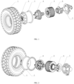
- the present invention relates to a technical field of new energy vehicles, more particularly to an electric wheel assembly with integrated hub motor and reducer.
- the planetary reducer 4 includes a sun gear 15 and a planet carrier integrated with the hub 16.
- the sun gear 15 is connected to an end of the motor rotor holder 36 close to the spoke plate 2 and serves as an input end of the planetary reducer 4, and the planet carrier serves as an output end of the planetary reducer 4.
- the braking system 6 includes a brake disc 21.
- the brake disc 21 is fitted over the motor rotor holder 36 through a brake disc connection sleeve 20 and located at an end of the rotor 34 sleeve away from the spoke plate 2.
- the braking system 6 brakes the electric wheel assembly 100 by braking the motor rotor holder 36.
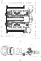
- the motor stator housing 31 may also be arranged with a cooling channel.
- the motor rotor holder 36 may also transfer an output torque of the motor.
- the motor outer end cap 37 and the motor inner end cap 30 may be arranged with a bearing positioning face, to limit axial displacement of the motor bearings 39.
- the motor bearings 39 are deep groove ball bearings, and the hub bearings 24 are tapered roller bearings.
- the types of the motor bearing 39 and the hub bearing 24 are not limited to the above two types, and the types of the motor bearing 39 and the hub bearing 24 can be changed according to specific conditions in practice.
- the hub 16 integrated with the planet carrier is not only the hub 16 of the electric wheel assembly 100, but also the planet carrier of the planetary reducer 4.
- the planet carrier is connected to the spoke plate 2.
- the planet carrier is provided with through holes fitted with the planet gear pin 11, an end of the planet gear pin 11 passes through the planet carrier, the spoke plate 2 and is locked on the spoke plate 2 through a nut and connection keys, and the other end of the planet gear pin 11 passes through the auxiliary planet carrier 14 and is positioned on the auxiliary planet carrier 14 through a shaft retaining ring.
- the planet gear pin 11 is provided with lubrication oil channels.
Landscapes
- Engineering & Computer Science (AREA)
- Transportation (AREA)
- Mechanical Engineering (AREA)
- Chemical & Material Sciences (AREA)
- Combustion & Propulsion (AREA)
- Power Engineering (AREA)
- Arrangement Or Mounting Of Propulsion Units For Vehicles (AREA)
Claims (15)
- Ensemble de roue électrique (100) avec un moteur de moyeu intégré, comprenant :une jante (3) adaptée pour monter un pneu (1) et ayant une plaque de rayons (2) au niveau d'une extrémité axiale de la jante (3) ;un moyeu (6) relié à la plaque de rayons (2) ;un ensemble de fusée d'essieu (7) comprenant un manchon de fusée (17), le manchon de fusée (17) étant monté sur une section d'arbre du moyeu (6), le manchon de fusée (17) et le moyeu (6) étant dotés d'un palier de moyeu (24) entre eux ;un moteur de rotor interne (5) prévu à l'intérieur de la jante (3) et comprenant :un carter moteur (41) comprenant un support de rotor de moteur (36) monté sur un côté externe du manchon de fusée (17),un rotor (34) ayant une structure creuse, montée et fixée sur le support de rotor de moteur (36), etun stator (33) inséré et fixé sur le carter moteur (41), le stator (33) étant monté sur un côté externe du rotor (34) ;un réducteur épicycloïdal (4) comprenant :un engrenage solaire (15) relié à une extrémité du support de rotor de moteur (36) près de la plaque de rayons (2) et étant une extrémité d'entrée du réducteur épicycloïdal (4), etun porte-satellite intégré avec le moyeu (6) et étant une extrémité de sortie du réducteur épicycloïdal (4) ; etun système de freinage (6) comprenant un disque de frein (21),caractérisé en ce quele disque de frein (21) est monté sur le support de rotor de moteur (36) via un manchon de liaison de disque de frein (20) et situé au niveau d'une extrémité du support de rotor de moteur (36) loin de la plaque de rayons (2), et le système de freinage (6) est configuré pour freiner l'ensemble de roue électrique (100) par freinage du support de rotor de moteur (36).
- Ensemble de roue électrique (100) selon la revendication 1, dans lequel le moteur de rotor interne (5) est un moteur à champ radial, ou un moteur à champ hybride radial-axial.
- Ensemble de roue électrique (100) selon la revendication 1, dans lequel le carter moteur (41) comprend en outre :un carter de stator de moteur (31) monté sur le stator (33) ;un capuchon d'extrémité interne de moteur (30) relié à un côté du carter de stator de moteur (31) loin de la plaque de rayons (2) et relié à l'ensemble de fusée d'essieu (7) ; etun capuchon d'extrémité externe de moteur (37) relié à un côté du carter de stator de moteur (31) près de la plaque de rayons (2),dans lequel le capuchon d'extrémité externe de moteur (37) et le support de rotor de moteur (36) sont dotés d'un palier de moteur (39) entre eux, et le capuchon d'extrémité interne de moteur (30) et le support de rotor de moteur (36) sont dotés d'un palier de moteur (39) entre eux.
- Ensemble de roue électrique (100) selon la revendication 1, dans lequel l'engrenage solaire (15) est monté sur une extrémité du support de rotor de moteur (36) près de la plaque de rayons (2), et une extrémité du support de rotor de moteur (36) loin de la plaque de rayons (2) est reliée au disque de frein (21) du système de freinage (6) via le manchon de liaison de disque de frein (20).
- Ensemble de roue électrique (100) selon la revendication 3, dans lequel le réducteur épicycloïdal (4) est un réducteur épicycloïdal à un étage (4), et le réducteur épicycloïdal (4) comprend en outre :un porte-satellite auxiliaire (14) monté sur une extrémité du porte-satellite loin de la plaque de rayons (2) ;une pluralité d'engrenages planétaires (13), chaque engrenage planétaire (13) étant monté entre le porte-satellite et le porte-satellite auxiliaire (14) via un axe d'engrenage planétaire (11) et s'engrenant avec l'engrenage solaire (15) pour transmettre une sortie de puissance par le moteur de rotor interne (5) ;un anneau denté (10) monté sur les engrenages planétaires (13) et s'engrenant avec les engrenages planétaires (13) ; etun support d'anneau denté (9) monté sur l'anneau denté (10), une extrémité du support d'anneau denté (9) étant reliée au carter de stator de moteur (31) et au capuchon d'extrémité externe de moteur (37), le support d'anneau denté (9) étant formé comme un manchon étagé progressivement étendu dans une direction loin de la plaque de rayons (2), et une face périphérique du support d'anneau denté (9) étant dotée d'une nervure de renforcement.
- Ensemble de roue électrique (100) selon la revendication 5, dans lequel chaque engrenage planétaire (13) emploie une structure d'anneau en forme de tour comprenant :un engrenage primaire s'engrenant avec l'engrenage solaire (15) ; etun engrenage secondaire disposé coaxialement avec l'engrenage primaire et s'engrenant avec l'anneau denté (10), le nombre de dents sur l'engrenage secondaire étant inférieur au nombre de dents sur l'engrenage primaire.
- Ensemble de roue électrique (100) selon la revendication 5, dans lequel le porte-satellite est doté d'un trou débouchant doté de l'axe d'engrenage planétaire (11), une extrémité de l'axe d'engrenage planétaire (11) passe à travers le porte-satellite et la plaque de rayons (2) et est verrouillée sur la plaque de rayons (2) cependant un écrou et une clé à liaison, l'autre extrémité de l'axe d'engrenage planétaire (11) passe à travers le porte-satellite auxiliaire (4) et est positionnée sur le porte-satellite auxiliaire (14) via un anneau de retenue d'arbre, et l'axe d'engrenage planétaire (11) est doté d'un canal d'huile de lubrification.
- Ensemble de roue électrique (100) selon la revendication 7, dans lequel le réducteur épicycloïdal (4) comprend en outre un axe de transfert de couple (42), une extrémité de l'axe de transfert de couple (42) passe à travers le porte-satellite auxiliaire (14) et est positionnée sur le porte-satellite auxiliaire (14) via un anneau de retenue d'arbre, et l'autre extrémité de l'axe de transfert de couple (42) est reliée au porte-satellite.
- Ensemble de roue électrique (100) selon la revendication 7, dans lequel le réducteur épicycloïdal (4) comprend en outre un capuchon d'extrémité d'anneau denté (38) relié à une extrémité du support d'anneau denté (9) près de la plaque de rayons (2), le capuchon d'extrémité d'anneau denté (38) est monté sur un côté externe du porte-satellite, le capuchon d'extrémité d'anneau denté (38), l'anneau denté (10), le support d'anneau denté (9) et le porte-satellite définissent une fente parmi eux, la fente est dotée d'un joint d'huile de réducteur (8) dedans, et le joint d'huile de réducteur (8) est verrouillé par le capuchon d'extrémité d'anneau denté (38) fixé sur le support d'anneau denté (9) via une vis.
- Ensemble de roue électrique (100) selon la revendication 3, dans lequel le capuchon d'extrémité interne de moteur (30) est doté d'une entrée d'huile de lubrification, le capuchon d'extrémité externe de moteur (37) est doté d'une sortie d'huile de lubrification, et la sortie d'huile de lubrification est ouverte vers un côté interne du réducteur épicycloïdal (4).
- Ensemble de roue électrique (100) selon la revendication 3, dans lequel le support de rotor de moteur (36) et le capuchon d'extrémité interne de moteur (30) sont dotés d'un joint d'huile de moteur (27) entre eux, le joint d'huile de moteur (27) est situé au niveau d'un côté du palier de moteur (39) loin de la plaque de rayons (2), une paroi périphérique interne du support de rotor de moteur (36) ou une paroi périphérique externe du manchon de fusée (17) est dotée d'une rainure de joint d'huile, la rainure de joint d'huile est dotée d'un joint d'huile de fusée (35) dedans, et le joint d'huile de fusée(35) est monté sur le manchon de fusée (17).
- Ensemble de roue électrique (100) selon la revendication 1, dans lequel une extrémité du moyeu (6) loin de la plaque de rayons (2) est montée avec un écrou rond (26), et une extrémité de l'écrou rond (26) bute contre une face d'extrémité du palier de moyeu (24) loin de la plaque de rayons (2).
- Ensemble de roue électrique (100) selon la revendication 1, dans lequel l'ensemble de fusée d'essieu (7) comprend en outre :une fusée (22) montée sur une extrémité du manchon de fusée (17) loin de la plaque de rayons (2), la fusée (22) étant dotée d'une ouverture de montage pour un bras oscillant de suspension, un bras de fusée d'essieu ou une biellette de direction ;un logement de fusée d'essieu (18), une extrémité du logement de fusée d'essieu (18) loin de la plaque de rayons (2) étant reliée à la fusée (22), et l'autre extrémité de celui-ci est doté d'une bride pour le support du carter moteur (41) ; etun capuchon d'extrémité étanche (25) enclenché dans un côté du manchon de fusée (17) loin de la plaque de rayons (2) et doté d'un trou de retour d'huile pour le reflux de l'huile de lubrification.
- Ensemble de roue électrique selon la revendication 13, dans lequel le système de freinage (6) comprend en outre :
un étrier de frein (23) relié au logement de fusée d'essieu (18) de l'ensemble de fusée d'essieu (7). - Ensemble de roue électrique (100) selon l'une quelconque des revendications 1 à 14, dans lequel le système de freinage (6) est un système de freinage mécanique à disque avec une pression pneumatique variable ou une pression hydraulique variable, l'ensemble de roue électrique (100) est apte à employer une forme de frein hybride électromécanique, et lorsque l'ensemble de roue électrique (100) est dans un mode de fonctionnement de freinage, le moteur de rotor interne (5) est apte à fournir un couple de freinage, et à fonctionner en synergie avec le système de freinage mécanique à disque avec une pression pneumatique variable ou une pression hydraulique variable.
Applications Claiming Priority (3)
| Application Number | Priority Date | Filing Date | Title |
|---|---|---|---|
| CN201820496964.3U CN208134060U (zh) | 2018-04-09 | 2018-04-09 | 一种集成轮毂电机的电动轮总成 |
| CN201810310347.4A CN108340768B (zh) | 2018-04-09 | 2018-04-09 | 一种集成轮毂电机的电动轮总成 |
| PCT/CN2018/113483 WO2019196395A1 (fr) | 2018-04-09 | 2018-11-01 | Ensemble roue électrique à moteur de moyeu intégré |
Publications (3)
| Publication Number | Publication Date |
|---|---|
| EP3778281A1 EP3778281A1 (fr) | 2021-02-17 |
| EP3778281A4 EP3778281A4 (fr) | 2021-12-22 |
| EP3778281B1 true EP3778281B1 (fr) | 2023-03-01 |
Family
ID=68163893
Family Applications (1)
| Application Number | Title | Priority Date | Filing Date |
|---|---|---|---|
| EP18914531.1A Active EP3778281B1 (fr) | 2018-04-09 | 2018-11-01 | Ensemble roue électrique à moteur de moyeu intégré |
Country Status (3)
| Country | Link |
|---|---|
| US (1) | US11772479B2 (fr) |
| EP (1) | EP3778281B1 (fr) |
| WO (1) | WO2019196395A1 (fr) |
Families Citing this family (34)
| Publication number | Priority date | Publication date | Assignee | Title |
|---|---|---|---|---|
| CN109250028B (zh) * | 2017-07-14 | 2022-02-25 | 罗伯特·博世有限公司 | 电动车辆及其车轮组件 |
| CN112135744B (zh) * | 2018-04-11 | 2024-12-06 | 德萨动力有限公司 | 车辆的悬架和牵引系统 |
| CN113329903A (zh) * | 2019-03-13 | 2021-08-31 | 舍弗勒技术股份两合公司 | 轮内驱动系统及机动车 |
| KR102708798B1 (ko) * | 2019-06-17 | 2024-09-24 | 현대모비스 주식회사 | 인휠 구동장치 |
| US11602951B2 (en) * | 2020-02-24 | 2023-03-14 | Bendix Commercial Vehicle Systems Llc | Splined drum and electric motor engagement assembly |
| CN111301150A (zh) * | 2020-03-20 | 2020-06-19 | 北京森汉科技有限公司 | 轮毂驱动轮 |
| CN113492669B (zh) * | 2020-04-01 | 2025-03-28 | 郭新堂 | 一种电动轮及车辆 |
| CN112519561A (zh) * | 2020-11-26 | 2021-03-19 | 中石化石油工程技术服务有限公司 | 一种自主移动巡检机器人的驱动车轮 |
| FR3121120B1 (fr) * | 2021-03-24 | 2023-03-17 | Jnov Tech | Roue motorisée électriquement pour plateforme mobile |
| CN113119713A (zh) * | 2021-04-21 | 2021-07-16 | 杭州恒业电机制造有限公司 | 一款高度集成电驱动轮 |
| AU2022277702A1 (en) | 2021-05-19 | 2023-12-14 | Razor Usa Llc | Motorized mid-drive unit |
| US12240559B2 (en) * | 2021-06-18 | 2025-03-04 | Razor Usa Llc | Hub motor arrangements, systems, and methods |
| KR20230011139A (ko) * | 2021-07-13 | 2023-01-20 | 현대모비스 주식회사 | 허브 베어링을 포함하는 휠 구조체 및 그 휠 구조체를 포함하는 자동차 |
| CN113443587B (zh) * | 2021-07-19 | 2022-08-05 | 淄博纽氏达特行星减速机有限公司 | 一种电动叉车驱动一体轮 |
| EP4385302A4 (fr) * | 2021-09-01 | 2024-12-25 | Globe (Jiangsu) Co., Ltd. | Outil de jardin |
| KR20230038008A (ko) * | 2021-09-10 | 2023-03-17 | 현대모비스 주식회사 | 인휠 구동장치 |
| CN113898703A (zh) * | 2021-10-15 | 2022-01-07 | 徐州工程学院 | 一种内置制动器的大型提升行星减速机 |
| CN114274762A (zh) * | 2022-01-17 | 2022-04-05 | 中国第一汽车股份有限公司 | 一种轮毂电机、转向节及制动器的集成结构 |
| CN114607718A (zh) * | 2022-03-04 | 2022-06-10 | 艾德斯汽车电机无锡有限公司 | 一种外置式盘式制动器结构 |
| CN114801702B (zh) * | 2022-05-10 | 2025-08-22 | 厦门金龙联合汽车工业有限公司 | 轮毂电机和转向电机互为冗余的车轮总成及其控制方法 |
| CN114919396A (zh) * | 2022-05-27 | 2022-08-19 | 吉林大学 | 一种集成单级减速器的轮毂电机 |
| WO2024022562A1 (fr) * | 2022-07-25 | 2024-02-01 | Continental Automotive Technologies GmbH | Module de puissance intégré à une fusée d'essieu |
| CN115622284B (zh) * | 2022-09-07 | 2023-06-27 | 江苏晨朗电子集团有限公司 | 一种便于装配的电动车用轮毂电机 |
| AU2023226632B2 (en) * | 2022-09-08 | 2024-12-05 | Asian Prime Sources Limited | Self-powered all terrain wheel |
| CA3209279A1 (fr) * | 2022-09-16 | 2024-03-16 | Greenworks (Jiangsu) Co., Ltd | Assemblage de moteur-roue et outil de jardinage |
| CN116123213A (zh) * | 2022-12-20 | 2023-05-16 | 内蒙古第一机械集团股份有限公司 | 一种功能集成化的轮毂轴承单元 |
| CN116674322B (zh) * | 2023-06-12 | 2025-09-09 | 于都县睿志机动车检测服务有限公司 | 一种机动车辆安全维护检测结构 |
| CN220884510U (zh) * | 2023-09-27 | 2024-05-03 | 王�华 | 一种露营车的驱动装置 |
| DE102023004701A1 (de) * | 2023-11-17 | 2025-05-22 | Mercedes-Benz Group AG | Radnabenantriebsvorrichtung für ein Kraftfahrzeug |
| CN117713444B (zh) * | 2024-02-06 | 2024-04-19 | 北京航空航天大学 | 一种集成托臂、电机、行星齿轮减速器的分布式驱动系统 |
| FR3158919A1 (fr) * | 2024-02-07 | 2025-08-08 | Poclain Hydraulics Industrie | Ensemble pour moteur-roue |
| CN119995246A (zh) * | 2024-09-23 | 2025-05-13 | 浙江鑫可精密机械有限公司 | 一种集成式电摩驱动系统 |
| CN119995248B (zh) * | 2025-01-10 | 2025-09-05 | 同济大学 | 一种一体化油冷的轮毂减速电动轮 |
| CN119636400A (zh) * | 2025-01-16 | 2025-03-18 | 吉林大学 | 一种适用于方程式赛车的四轮独立轮边减速驱动系统 |
Family Cites Families (10)
| Publication number | Priority date | Publication date | Assignee | Title |
|---|---|---|---|---|
| DE10014131A1 (de) * | 2000-03-22 | 2001-09-27 | Zahnradfabrik Friedrichshafen | Radantrieb zum Antrieb eines Fahzeugrades |
| DE10121372A1 (de) * | 2001-05-02 | 2002-11-07 | Krauss Maffei Wegmann Gmbh & C | Allradangetriebenes Kraftfahrzeug, insbesondere militärisches Kraftfahrzeug, mit dieselelektrischer Antriebsvorrichtung |
| JP4724075B2 (ja) * | 2006-08-29 | 2011-07-13 | 本田技研工業株式会社 | ホイール回転装置 |
| JP4758852B2 (ja) * | 2006-08-29 | 2011-08-31 | 本田技研工業株式会社 | ホイール回転装置のブレーキ構造 |
| KR101621982B1 (ko) * | 2010-11-16 | 2016-05-31 | 현대모비스 주식회사 | 인휠 구동시스템 |
| KR20160050742A (ko) * | 2014-10-30 | 2016-05-11 | 현대모비스 주식회사 | 인휠 구동장치 |
| CN105150826A (zh) * | 2015-09-07 | 2015-12-16 | 南京理工大学 | 紧凑的分布式驱动电机系统及具有分布式驱动电机系统的车辆 |
| CN105270161B (zh) * | 2015-10-28 | 2018-10-02 | 湖北航天技术研究院特种车辆技术中心 | 一种轮边电机驱动装置 |
| CN107458210A (zh) * | 2017-07-14 | 2017-12-12 | 山东理工大学 | 一种基于磁分路式混合励磁结构的一体化集成电动轮系统 |
| CN108340768B (zh) * | 2018-04-09 | 2020-06-02 | 清华大学 | 一种集成轮毂电机的电动轮总成 |
-
2018
- 2018-11-01 EP EP18914531.1A patent/EP3778281B1/fr active Active
- 2018-11-01 WO PCT/CN2018/113483 patent/WO2019196395A1/fr not_active Ceased
-
2020
- 2020-10-08 US US17/066,461 patent/US11772479B2/en active Active
Also Published As
| Publication number | Publication date |
|---|---|
| US20210031615A1 (en) | 2021-02-04 |
| EP3778281A4 (fr) | 2021-12-22 |
| EP3778281A1 (fr) | 2021-02-17 |
| US11772479B2 (en) | 2023-10-03 |
| WO2019196395A1 (fr) | 2019-10-17 |
Similar Documents
| Publication | Publication Date | Title |
|---|---|---|
| EP3778281B1 (fr) | Ensemble roue électrique à moteur de moyeu intégré | |
| CN108340768B (zh) | 一种集成轮毂电机的电动轮总成 | |
| CN109130839B (zh) | 一种适用于双胎并装车轮的电动轮总成、车桥及车辆 | |
| CN109109640B (zh) | 一种同轴式独立电驱桥及电动汽车 | |
| US6752227B1 (en) | Final drive for driving a vehicle wheel | |
| US6328123B1 (en) | Electrical drive for a wheel hub | |
| US7530416B2 (en) | Motor-driven wheel driving apparatus | |
| WO2019238042A1 (fr) | Groupe motopropulseur d'entraînement électrique intégré | |
| CN210733818U (zh) | 一种集成式轮毂电机总成及电动车 | |
| CN111361358A (zh) | 一种重载电动轮 | |
| CN210733819U (zh) | 一种一体化电动轮系统及电动车 | |
| JPH04185207A (ja) | 減速機付ホィールモータ | |
| CN115195460A (zh) | 电驱系统及车辆 | |
| KR20210136026A (ko) | 인휠 구동 시스템 및 모터 차량 | |
| CN110154737A (zh) | 一种低速大扭矩电动轮装置和电动汽车 | |
| CN103072476A (zh) | 电动车的后桥电动力驱动装置 | |
| CN102782999A (zh) | 内轮电动机驱动装置及其设计方法 | |
| CN208134060U (zh) | 一种集成轮毂电机的电动轮总成 | |
| CN211969079U (zh) | 一种重载电动轮 | |
| WO2024055593A1 (fr) | Ensemble de rendement de puissance, groupe motopropulseur et véhicule | |
| CN221214447U (zh) | 一种用于轮毂驱动的驱动装置 | |
| CN215360772U (zh) | 车桥总成及全地形车 | |
| US12441181B2 (en) | Integrated drive system and electric vehicle | |
| CN222746567U (zh) | 一种二级行星减速型羊角型传动箱体 | |
| CN220242987U (zh) | 一种轮边驱动总成 |
Legal Events
| Date | Code | Title | Description |
|---|---|---|---|
| STAA | Information on the status of an ep patent application or granted ep patent |
Free format text: STATUS: THE INTERNATIONAL PUBLICATION HAS BEEN MADE |
|
| PUAI | Public reference made under article 153(3) epc to a published international application that has entered the european phase |
Free format text: ORIGINAL CODE: 0009012 |
|
| STAA | Information on the status of an ep patent application or granted ep patent |
Free format text: STATUS: REQUEST FOR EXAMINATION WAS MADE |
|
| 17P | Request for examination filed |
Effective date: 20201106 |
|
| AK | Designated contracting states |
Kind code of ref document: A1 Designated state(s): AL AT BE BG CH CY CZ DE DK EE ES FI FR GB GR HR HU IE IS IT LI LT LU LV MC MK MT NL NO PL PT RO RS SE SI SK SM TR |
|
| AX | Request for extension of the european patent |
Extension state: BA ME |
|
| DAV | Request for validation of the european patent (deleted) | ||
| DAX | Request for extension of the european patent (deleted) | ||
| A4 | Supplementary search report drawn up and despatched |
Effective date: 20211122 |
|
| RIC1 | Information provided on ipc code assigned before grant |
Ipc: B60T 1/06 20060101ALI20211116BHEP Ipc: B60K 17/04 20060101ALI20211116BHEP Ipc: B60K 7/00 20060101AFI20211116BHEP |
|
| GRAP | Despatch of communication of intention to grant a patent |
Free format text: ORIGINAL CODE: EPIDOSNIGR1 |
|
| RIC1 | Information provided on ipc code assigned before grant |
Ipc: B60B 27/00 20060101ALI20220816BHEP Ipc: B60T 1/06 20060101ALI20220816BHEP Ipc: B60K 17/04 20060101ALI20220816BHEP Ipc: B60K 7/00 20060101AFI20220816BHEP |
|
| STAA | Information on the status of an ep patent application or granted ep patent |
Free format text: STATUS: GRANT OF PATENT IS INTENDED |
|
| INTG | Intention to grant announced |
Effective date: 20220922 |
|
| GRAS | Grant fee paid |
Free format text: ORIGINAL CODE: EPIDOSNIGR3 |
|
| GRAA | (expected) grant |
Free format text: ORIGINAL CODE: 0009210 |
|
| STAA | Information on the status of an ep patent application or granted ep patent |
Free format text: STATUS: THE PATENT HAS BEEN GRANTED |
|
| AK | Designated contracting states |
Kind code of ref document: B1 Designated state(s): AL AT BE BG CH CY CZ DE DK EE ES FI FR GB GR HR HU IE IS IT LI LT LU LV MC MK MT NL NO PL PT RO RS SE SI SK SM TR |
|
| REG | Reference to a national code |
Ref country code: GB Ref legal event code: FG4D |
|
| REG | Reference to a national code |
Ref country code: CH Ref legal event code: EP Ref country code: AT Ref legal event code: REF Ref document number: 1550741 Country of ref document: AT Kind code of ref document: T Effective date: 20230315 |
|
| REG | Reference to a national code |
Ref country code: DE Ref legal event code: R096 Ref document number: 602018046840 Country of ref document: DE |
|
| REG | Reference to a national code |
Ref country code: IE Ref legal event code: FG4D |
|
| REG | Reference to a national code |
Ref country code: SE Ref legal event code: TRGR |
|
| REG | Reference to a national code |
Ref country code: LT Ref legal event code: MG9D |
|
| REG | Reference to a national code |
Ref country code: NL Ref legal event code: MP Effective date: 20230301 |
|
| PG25 | Lapsed in a contracting state [announced via postgrant information from national office to epo] |
Ref country code: RS Free format text: LAPSE BECAUSE OF FAILURE TO SUBMIT A TRANSLATION OF THE DESCRIPTION OR TO PAY THE FEE WITHIN THE PRESCRIBED TIME-LIMIT Effective date: 20230301 Ref country code: NO Free format text: LAPSE BECAUSE OF FAILURE TO SUBMIT A TRANSLATION OF THE DESCRIPTION OR TO PAY THE FEE WITHIN THE PRESCRIBED TIME-LIMIT Effective date: 20230601 Ref country code: LV Free format text: LAPSE BECAUSE OF FAILURE TO SUBMIT A TRANSLATION OF THE DESCRIPTION OR TO PAY THE FEE WITHIN THE PRESCRIBED TIME-LIMIT Effective date: 20230301 Ref country code: LT Free format text: LAPSE BECAUSE OF FAILURE TO SUBMIT A TRANSLATION OF THE DESCRIPTION OR TO PAY THE FEE WITHIN THE PRESCRIBED TIME-LIMIT Effective date: 20230301 Ref country code: HR Free format text: LAPSE BECAUSE OF FAILURE TO SUBMIT A TRANSLATION OF THE DESCRIPTION OR TO PAY THE FEE WITHIN THE PRESCRIBED TIME-LIMIT Effective date: 20230301 Ref country code: ES Free format text: LAPSE BECAUSE OF FAILURE TO SUBMIT A TRANSLATION OF THE DESCRIPTION OR TO PAY THE FEE WITHIN THE PRESCRIBED TIME-LIMIT Effective date: 20230301 |
|
| P01 | Opt-out of the competence of the unified patent court (upc) registered |
Effective date: 20230622 |
|
| REG | Reference to a national code |
Ref country code: AT Ref legal event code: MK05 Ref document number: 1550741 Country of ref document: AT Kind code of ref document: T Effective date: 20230301 |
|
| PG25 | Lapsed in a contracting state [announced via postgrant information from national office to epo] |
Ref country code: PL Free format text: LAPSE BECAUSE OF FAILURE TO SUBMIT A TRANSLATION OF THE DESCRIPTION OR TO PAY THE FEE WITHIN THE PRESCRIBED TIME-LIMIT Effective date: 20230301 Ref country code: NL Free format text: LAPSE BECAUSE OF FAILURE TO SUBMIT A TRANSLATION OF THE DESCRIPTION OR TO PAY THE FEE WITHIN THE PRESCRIBED TIME-LIMIT Effective date: 20230301 Ref country code: GR Free format text: LAPSE BECAUSE OF FAILURE TO SUBMIT A TRANSLATION OF THE DESCRIPTION OR TO PAY THE FEE WITHIN THE PRESCRIBED TIME-LIMIT Effective date: 20230602 Ref country code: FI Free format text: LAPSE BECAUSE OF FAILURE TO SUBMIT A TRANSLATION OF THE DESCRIPTION OR TO PAY THE FEE WITHIN THE PRESCRIBED TIME-LIMIT Effective date: 20230301 |
|
| PG25 | Lapsed in a contracting state [announced via postgrant information from national office to epo] |
Ref country code: SM Free format text: LAPSE BECAUSE OF FAILURE TO SUBMIT A TRANSLATION OF THE DESCRIPTION OR TO PAY THE FEE WITHIN THE PRESCRIBED TIME-LIMIT Effective date: 20230301 Ref country code: RO Free format text: LAPSE BECAUSE OF FAILURE TO SUBMIT A TRANSLATION OF THE DESCRIPTION OR TO PAY THE FEE WITHIN THE PRESCRIBED TIME-LIMIT Effective date: 20230301 Ref country code: PT Free format text: LAPSE BECAUSE OF FAILURE TO SUBMIT A TRANSLATION OF THE DESCRIPTION OR TO PAY THE FEE WITHIN THE PRESCRIBED TIME-LIMIT Effective date: 20230703 Ref country code: EE Free format text: LAPSE BECAUSE OF FAILURE TO SUBMIT A TRANSLATION OF THE DESCRIPTION OR TO PAY THE FEE WITHIN THE PRESCRIBED TIME-LIMIT Effective date: 20230301 Ref country code: CZ Free format text: LAPSE BECAUSE OF FAILURE TO SUBMIT A TRANSLATION OF THE DESCRIPTION OR TO PAY THE FEE WITHIN THE PRESCRIBED TIME-LIMIT Effective date: 20230301 Ref country code: AT Free format text: LAPSE BECAUSE OF FAILURE TO SUBMIT A TRANSLATION OF THE DESCRIPTION OR TO PAY THE FEE WITHIN THE PRESCRIBED TIME-LIMIT Effective date: 20230301 |
|
| PG25 | Lapsed in a contracting state [announced via postgrant information from national office to epo] |
Ref country code: SK Free format text: LAPSE BECAUSE OF FAILURE TO SUBMIT A TRANSLATION OF THE DESCRIPTION OR TO PAY THE FEE WITHIN THE PRESCRIBED TIME-LIMIT Effective date: 20230301 Ref country code: IS Free format text: LAPSE BECAUSE OF FAILURE TO SUBMIT A TRANSLATION OF THE DESCRIPTION OR TO PAY THE FEE WITHIN THE PRESCRIBED TIME-LIMIT Effective date: 20230701 |
|
| REG | Reference to a national code |
Ref country code: DE Ref legal event code: R097 Ref document number: 602018046840 Country of ref document: DE |
|
| PLBE | No opposition filed within time limit |
Free format text: ORIGINAL CODE: 0009261 |
|
| STAA | Information on the status of an ep patent application or granted ep patent |
Free format text: STATUS: NO OPPOSITION FILED WITHIN TIME LIMIT |
|
| PG25 | Lapsed in a contracting state [announced via postgrant information from national office to epo] |
Ref country code: SI Free format text: LAPSE BECAUSE OF FAILURE TO SUBMIT A TRANSLATION OF THE DESCRIPTION OR TO PAY THE FEE WITHIN THE PRESCRIBED TIME-LIMIT Effective date: 20230301 Ref country code: DK Free format text: LAPSE BECAUSE OF FAILURE TO SUBMIT A TRANSLATION OF THE DESCRIPTION OR TO PAY THE FEE WITHIN THE PRESCRIBED TIME-LIMIT Effective date: 20230301 |
|
| 26N | No opposition filed |
Effective date: 20231204 |
|
| REG | Reference to a national code |
Ref country code: CH Ref legal event code: PL |
|
| PG25 | Lapsed in a contracting state [announced via postgrant information from national office to epo] |
Ref country code: MC Free format text: LAPSE BECAUSE OF FAILURE TO SUBMIT A TRANSLATION OF THE DESCRIPTION OR TO PAY THE FEE WITHIN THE PRESCRIBED TIME-LIMIT Effective date: 20230301 |
|
| PG25 | Lapsed in a contracting state [announced via postgrant information from national office to epo] |
Ref country code: LU Free format text: LAPSE BECAUSE OF NON-PAYMENT OF DUE FEES Effective date: 20231101 |
|
| PG25 | Lapsed in a contracting state [announced via postgrant information from national office to epo] |
Ref country code: CH Free format text: LAPSE BECAUSE OF NON-PAYMENT OF DUE FEES Effective date: 20231130 |
|
| PG25 | Lapsed in a contracting state [announced via postgrant information from national office to epo] |
Ref country code: MC Free format text: LAPSE BECAUSE OF FAILURE TO SUBMIT A TRANSLATION OF THE DESCRIPTION OR TO PAY THE FEE WITHIN THE PRESCRIBED TIME-LIMIT Effective date: 20230301 Ref country code: LU Free format text: LAPSE BECAUSE OF NON-PAYMENT OF DUE FEES Effective date: 20231101 Ref country code: CH Free format text: LAPSE BECAUSE OF NON-PAYMENT OF DUE FEES Effective date: 20231130 |
|
| REG | Reference to a national code |
Ref country code: IE Ref legal event code: MM4A |
|
| PG25 | Lapsed in a contracting state [announced via postgrant information from national office to epo] |
Ref country code: IE Free format text: LAPSE BECAUSE OF NON-PAYMENT OF DUE FEES Effective date: 20231101 |
|
| PG25 | Lapsed in a contracting state [announced via postgrant information from national office to epo] |
Ref country code: IE Free format text: LAPSE BECAUSE OF NON-PAYMENT OF DUE FEES Effective date: 20231101 |
|
| PG25 | Lapsed in a contracting state [announced via postgrant information from national office to epo] |
Ref country code: BG Free format text: LAPSE BECAUSE OF FAILURE TO SUBMIT A TRANSLATION OF THE DESCRIPTION OR TO PAY THE FEE WITHIN THE PRESCRIBED TIME-LIMIT Effective date: 20230301 |
|
| PG25 | Lapsed in a contracting state [announced via postgrant information from national office to epo] |
Ref country code: BG Free format text: LAPSE BECAUSE OF FAILURE TO SUBMIT A TRANSLATION OF THE DESCRIPTION OR TO PAY THE FEE WITHIN THE PRESCRIBED TIME-LIMIT Effective date: 20230301 |
|
| PG25 | Lapsed in a contracting state [announced via postgrant information from national office to epo] |
Ref country code: CY Free format text: LAPSE BECAUSE OF FAILURE TO SUBMIT A TRANSLATION OF THE DESCRIPTION OR TO PAY THE FEE WITHIN THE PRESCRIBED TIME-LIMIT; INVALID AB INITIO Effective date: 20181101 |
|
| PG25 | Lapsed in a contracting state [announced via postgrant information from national office to epo] |
Ref country code: HU Free format text: LAPSE BECAUSE OF FAILURE TO SUBMIT A TRANSLATION OF THE DESCRIPTION OR TO PAY THE FEE WITHIN THE PRESCRIBED TIME-LIMIT; INVALID AB INITIO Effective date: 20181101 |
|
| PG25 | Lapsed in a contracting state [announced via postgrant information from national office to epo] |
Ref country code: TR Free format text: LAPSE BECAUSE OF FAILURE TO SUBMIT A TRANSLATION OF THE DESCRIPTION OR TO PAY THE FEE WITHIN THE PRESCRIBED TIME-LIMIT Effective date: 20230301 |
|
| PGFP | Annual fee paid to national office [announced via postgrant information from national office to epo] |
Ref country code: DE Payment date: 20251014 Year of fee payment: 8 |
|
| PGFP | Annual fee paid to national office [announced via postgrant information from national office to epo] |
Ref country code: GB Payment date: 20251016 Year of fee payment: 8 |
|
| PGFP | Annual fee paid to national office [announced via postgrant information from national office to epo] |
Ref country code: IT Payment date: 20251030 Year of fee payment: 8 |
|
| PGFP | Annual fee paid to national office [announced via postgrant information from national office to epo] |
Ref country code: FR Payment date: 20251023 Year of fee payment: 8 |
|
| PGFP | Annual fee paid to national office [announced via postgrant information from national office to epo] |
Ref country code: BE Payment date: 20251015 Year of fee payment: 8 |
|
| PGFP | Annual fee paid to national office [announced via postgrant information from national office to epo] |
Ref country code: SE Payment date: 20251028 Year of fee payment: 8 |