EP3778366A1 - Fernsteuerungshebelanordnung - Google Patents
Fernsteuerungshebelanordnung Download PDFInfo
- Publication number
- EP3778366A1 EP3778366A1 EP20200637.5A EP20200637A EP3778366A1 EP 3778366 A1 EP3778366 A1 EP 3778366A1 EP 20200637 A EP20200637 A EP 20200637A EP 3778366 A1 EP3778366 A1 EP 3778366A1
- Authority
- EP
- European Patent Office
- Prior art keywords
- lever
- clamp
- assembly
- assembly according
- spherical
- Prior art date
- Legal status (The legal status is an assumption and is not a legal conclusion. Google has not performed a legal analysis and makes no representation as to the accuracy of the status listed.)
- Withdrawn
Links
Images



Classifications
-
- F—MECHANICAL ENGINEERING; LIGHTING; HEATING; WEAPONS; BLASTING
- F16—ENGINEERING ELEMENTS AND UNITS; GENERAL MEASURES FOR PRODUCING AND MAINTAINING EFFECTIVE FUNCTIONING OF MACHINES OR INSTALLATIONS; THERMAL INSULATION IN GENERAL
- F16C—SHAFTS; FLEXIBLE SHAFTS; ELEMENTS OR CRANKSHAFT MECHANISMS; ROTARY BODIES OTHER THAN GEARING ELEMENTS; BEARINGS
- F16C1/00—Flexible shafts; Mechanical means for transmitting movement in a flexible sheathing
- F16C1/10—Means for transmitting linear movement in a flexible sheathing, e.g. "Bowden-mechanisms"
- F16C1/12—Arrangements for transmitting movement to or from the flexible member
-
- B—PERFORMING OPERATIONS; TRANSPORTING
- B62—LAND VEHICLES FOR TRAVELLING OTHERWISE THAN ON RAILS
- B62L—BRAKES SPECIALLY ADAPTED FOR CYCLES
- B62L3/00—Brake-actuating mechanisms; Arrangements thereof
- B62L3/02—Brake-actuating mechanisms; Arrangements thereof for control by a hand lever
-
- B—PERFORMING OPERATIONS; TRANSPORTING
- B62—LAND VEHICLES FOR TRAVELLING OTHERWISE THAN ON RAILS
- B62K—CYCLES; CYCLE FRAMES; CYCLE STEERING DEVICES; RIDER-OPERATED TERMINAL CONTROLS SPECIALLY ADAPTED FOR CYCLES; CYCLE AXLE SUSPENSIONS; CYCLE SIDECARS, FORECARS, OR THE LIKE
- B62K23/00—Rider-operated controls specially adapted for cycles, i.e. means for initiating control operations, e.g. levers, grips
- B62K23/02—Rider-operated controls specially adapted for cycles, i.e. means for initiating control operations, e.g. levers, grips hand actuated
- B62K23/06—Levers
-
- B—PERFORMING OPERATIONS; TRANSPORTING
- B62—LAND VEHICLES FOR TRAVELLING OTHERWISE THAN ON RAILS
- B62M—RIDER PROPULSION OF WHEELED VEHICLES OR SLEDGES; POWERED PROPULSION OF SLEDGES OR SINGLE-TRACK CYCLES; TRANSMISSIONS SPECIALLY ADAPTED FOR SUCH VEHICLES
- B62M25/00—Actuators for gearing speed-change mechanisms specially adapted for cycles
- B62M25/02—Actuators for gearing speed-change mechanisms specially adapted for cycles with mechanical transmitting systems, e.g. cables, levers
-
- B—PERFORMING OPERATIONS; TRANSPORTING
- B62—LAND VEHICLES FOR TRAVELLING OTHERWISE THAN ON RAILS
- B62M—RIDER PROPULSION OF WHEELED VEHICLES OR SLEDGES; POWERED PROPULSION OF SLEDGES OR SINGLE-TRACK CYCLES; TRANSMISSIONS SPECIALLY ADAPTED FOR SUCH VEHICLES
- B62M25/00—Actuators for gearing speed-change mechanisms specially adapted for cycles
- B62M25/02—Actuators for gearing speed-change mechanisms specially adapted for cycles with mechanical transmitting systems, e.g. cables, levers
- B62M25/04—Actuators for gearing speed-change mechanisms specially adapted for cycles with mechanical transmitting systems, e.g. cables, levers hand actuated
-
- F—MECHANICAL ENGINEERING; LIGHTING; HEATING; WEAPONS; BLASTING
- F16—ENGINEERING ELEMENTS AND UNITS; GENERAL MEASURES FOR PRODUCING AND MAINTAINING EFFECTIVE FUNCTIONING OF MACHINES OR INSTALLATIONS; THERMAL INSULATION IN GENERAL
- F16C—SHAFTS; FLEXIBLE SHAFTS; ELEMENTS OR CRANKSHAFT MECHANISMS; ROTARY BODIES OTHER THAN GEARING ELEMENTS; BEARINGS
- F16C1/00—Flexible shafts; Mechanical means for transmitting movement in a flexible sheathing
- F16C1/10—Means for transmitting linear movement in a flexible sheathing, e.g. "Bowden-mechanisms"
Definitions
- the present invention relates to a remote control lever assembly.
- Remote control lever assemblies for bicycle adjustable height seat posts typically include a pivoting lever, a body on which the pivoting lever is hinged, a clamp for connecting the body of the assembly to a bicycle handlebar, and a fastener for tightening the clamp to the handlebar.
- a flexible cable operatively connected to the height adjustable seat post, is linked to the pivoting lever; as the lever is moved, the flexible cable is pulled through the body, and activates a valve or mechanism within the seat post.
- Typical bicycles that use height adjustable seat posts have right and left brake levers and grips, and a gear shifter on the right and possibly also on the left.
- the remote control lever assembly can potentially be mounted in four positions on the handlebar: top right, bottom right, top left, and bottom left.
- Most remote control lever assemblies can only be mounted in two positions: top right and bottom left, or bottom right and top left.
- remote control lever assemblies can be mounted in all four positions: they typically require some disassembly and reassembly in order to achieve this.
- remote control lever assembly is mounted, based, for example, on their bicycle configuration or on possible physical limitations.
- Twist shifters are higher profile than trigger shifters: usually it is desirable, for remote control lever assemblies, to be as low profile as possible.
- lever assembly When a lever assembly is designed for trigger shifters, then normally it will not fit handlebars with twist shifters, unless the assembly is overly high profile.
- the cable exit from the remote lever assembly interferes with the brake lever of shifter mounts, or with cable routing.
- One kind of existing remote control lever assembly design is not traditionally hinged, but instead it comprises a joystick-like actuation lever, that can be pushed or pulled in any direction.
- This design is not as comfortable to use, because it requires pushing on a round rod rather than a larger pad that better spreads out the load.
- lever can be pushed in any direction, it often has certain directions where it collides with the shifters, grips, or mounting hardware.
- this design has the same lack of adjustability as many of the hinged lever designs.
- Another existing remote control lever assembly design is suitable for pushing ad hydraulic fluid rather than pulling a cable.
- the same adjustable position limitations occurs as cable pull levers.
- the technical aim of the present invention is therefore to improve the state of the art. Within such technical aim, it is an object of the invention to develop a remote control lever assembly that can be effectively mounted on the handlebar in any desired position of the latter.
- Another object of the present invention is to devise a remote control lever assembly in which the mounting position on the handlebar can be finely adjusted in order to avoid collisions or interferences with other functional parts like brake levers, shifters, and/or the respective cables.
- a further object of the invention is to develop a remote control lever assembly that can be indifferently actuated by thumb pushing or finger pulling, depending on the choice of the user.
- Still another object of the invention is to devise a remote control lever assembly which allows to achieve the foregoing objects with a simple and economic solution.
- a remote control lever assembly suitable to be mounted on bicycle handlebars and the like, comprising a coupling portion for fixing the assembly to the bicycle handlebar, a lever support, and a lever movably connected to the lever support; the assembly further comprises a spherical joint, adjustably connecting said lever support to said coupling portion.
- the spherical joint allows an extensive angular and rotational fine position adjustment of the lever support with respect to the coupling portion.
- the spherical joint comprises a spherical housing connected to the coupling portion, and a spherical protrusion of the lever support adjustably engaging the spherical housing.
- the coupling portion comprises a first clamp, and the assembly further comprises a second clamp, connected to the first claim, in which the spherical housing is defined.
- a clamp fastener is foreseen suitable to simultaneously fix the first clamp to the handlebar and the second clamp to the spherical protrusion.
- the assembly further comprises an actuation cable, connected to the lever;
- the lever support comprises a first passing channel of the spherical housing, through which the actuation cable passes;
- the lever comprises a second passing channel, through which the actuation cable passes.
- the lever comprises a cable set screw suitable to bend the end of the actuation cable towards the back of the lever itself, preventing the cable end to interfere with user's fingers while actuating the lever.
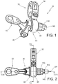
- a remote control lever assembly according to the invention is wholly indicated with 10.
- the remote control lever assembly 10 is of the kind suitable for actuating, for example, an adjustable height seat post, or any other device, installed on the bicycle, which needs a control operable by a lever, or the like.
- the assembly 10 according to the invention is suitable to be mounted on a bicycle handlebar 20, or the like.
- the assembly 10 comprises a coupling portion, wholly indicated with 30, for fixing the assembly 10 itself on the handlebar 20.
- the assembly 10 further comprises a lever support 40, and a lever 50 movably connected to the lever support 40.
- the assembly 10 comprises a spherical joint, wholly indicated with 60, adjustably connecting the lever support 40 to the coupling portion 30.
- the spherical joint 60 offers the user the ability to orient the lever support 40 - and therefore the lever 50 - in the desired position in order not to interfere to other means mounted on the handlebar 20, and in order to achieve the best position for the operation of the lever 50, as preferred by the user.
- the spherical joint 60 comprises a spherical housing 70.
- the spherical housing 70 is connected to the coupling portion 30.
- the spherical joint 60 further comprises a spherical protrusion 80 of the lever support 40.
- the spherical protrusion 80 adjustably engages the spherical housing 70.
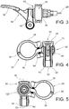
- the coupling portion 30 comprises a first clamp 32.
- the first clamp 32 includes a first clamp member 34 and a second clamp member 36, hinged in a pivot 38.
- the first clamp member 34 and the second clamp member 36 are both substantially C-shaped.
- the first clamp member 34 and the second clamp member 36 have dimensions and shape such as to fit the external surface of different handlebars 20, having possibly various cross-sections.
- the assembly 10 comprises a second clamp, wholly indicated with 90.
- the second clamp 90 is connected to the first clamp 32.
- the above cited spherical housing 70 is defined in the second clamp 90: in particular, the spherical housing 70 is defined in the inner surface of the second clamp 90.
- the second clamp 90 is substantially in form of a C-bent strip, and its inner surface is spherically conformed.
- the spherical housing 70 defined in the second clamp 90 has substantially the same radius of the spherical protrusion 80.
- the second clamp 90 comprises a first terminal portion 92 and a second terminal portion 94 which are opposite each other.
- the first terminal portion 92 of the second clamp 90 is integral to the free extremity 33 of the first clamp member 34.
- first clamp 32 and the second clamp 90 have respective openings substantially facing each other with respect to the clamp fastener 100, allowing to obtain the advantages referred to below.
- the assembly 10 comprises a clamp fastener 100.
- the clamp fastener 100 is suitable to simultaneously fix the first clamp 90 to the handlebar 20, and the second clamp 32 to the spherical protrusion 80.
- the user acting on a single clamp fastener 100, the user can perform, in a single operation the locking of the whole assembly 10 with respect to the handlebar 20, and the locking of the spherical protrusion 80 inside the spherical housing 70, as better explained hereafter.
- the clamp fastener 100 comprises a clamp screw, engaged in a common hole 110 passing through the first clamp 32 and the second clamp 90.
- the common hole 110 comprises a smooth portion 112 passing through the free end 37 of the second clamp member 36.
- the common hole 110 comprises a hole 114 and a threaded portion 116.
- the hole 114 is passing through the first terminal portion 92 of the second clamp 90 (linked to the free extremity 33 of the first clamp member 34).
- the threaded portion 116 is passing through the second terminal portion 94 of the second clamp 90.
- the lever 50 is hinged to the lever support 40.
- lever support 40 and the lever 50 include respective linkage portions 42,52, connected by hinge fasteners 44,54.
- the linkage portions 42 of the lever support 40 are shaped like identical opposite appendages defining a seat 46 between them, in which the linkage portion 52 of the lever 50 engages.
- the lever 50 comprises an actuating end 56.
- the actuating end 56 is suitable for operating the lever 50.
- the remote control lever assembly 10 comprises an actuation cable 120, connected to the lever 50.
- the lever support 40 comprises a first passing channel 122 foreseen in the spherical protrusion 80, through which the actuation cable passes 120.
- the axis of the first passing channel 122 coincides with the symmetry axis of the spherical protrusion 80.
- the first passing channel 122 is at least partially, or totally, threaded.
- the lever 50 comprises a second passing channel 124, through which the actuation cable 120 passes.
- the second passing channel 124 is coaxial, or substantially coaxial, to the first passing channel 122.
- the lever 50 comprises a recess 51, foreseen in its back.
- the second passing channel 124 intercepts the recess 51.
- the lever 50 further comprises a cable set screw 53.
- the cable set screw 53 is suitable to bend the end 121 of the actuation cable 120 towards the back of the lever 50.
- the cable set screw 53 is engaged in a threaded hole 55 intercepting the second passing channel 124.
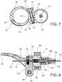
- figure 8 shows a section of the assembly 10 before the actuation cable 120 has been tightened into position by the cable set screw 53.
- the actuation cable 120 is straight before tightening the cable set screw 53 in the threaded hole 55.
- Figure 9 shows a section of the assembly 10 after actuation cable 120 has been tightened into position by the cable set screw 53.
- Tightening the cable set screw 53 secures the actuation cable 120 to the lever 50, and at the same time it automatically bends the actuation cable 120 into a curve 123 which spring loads the end 121 of the actuation cable 120 against the backside of the lever 50: in particular, the end 121 of the actuation cable 120 engages the recess 51 of the lever 50.
- the spherical protrusion 80 comprises a recessed seat 82 for the engagement of an adjustable barrel 130 for the fine tuning of the relative actuation cable 120 length between the assembly 10 and the device actuated by the lever 50, for example the height adjustable seat post (not shown in the figures).
- the adjustable barrel 130 is slidably coupled to an adjustable screw 140, through which the actuation cable 120 passes.
- the adjustable screw 140 has a threaded portion engaged in the first passing channel 122 of the spherical protrusion 80, as shown for example in figure 9 .
- a compression spring 150 is trapped between rest surfaces 132,142 respectively of the adjustable barrel 130 and of the adjustable screw 140.
- the compression spring 150 keeps the adjustable barrel 130 permanently engaged in the recessed seat 82.
- the adjustable screw 140 comprises a front seat 144 engaging the cable housing 160.
- Figures 10 through 14 show some of the adjustments possible because of relative movement of the spherical protrusion 80 within the spherical housing 70.
- FIGS 13 and 14 show that the lever support 40 can be actually inclined in any plane with respect to the first clamp 32.
- the user can place the lever 50 in the most comfortable position, in order to have easy access to the lever 50 itself while riding.
- FIGS 15 through 19 show various mounting options of the assembly 10 according to the invention on the bicycle handlebar 20.
- figure 15 shows the assembly 10 mounted in top right position with respect to the bicycle handlebar 20.
- Figure 16 shows the assembly 10 mounted in bottom right position with respect to the bicycle handlebar 20.
- Figure 17 shows the assembly 10 mounted in bottom left position with respect to the bicycle handlebar 20.
- Figure 18 shows the assembly 10 mounted in top left position with respect to the bicycle handlebar 20.
- Figure 19 shows the assembly 10 mounted in top right position with respect to the bicycle handlebar, and in a finger pull orientation.
- the assembly 10 can fit both trigger and twist shifters, without being higher profile than necessary.
- the assembly 10 according to the invention can be easily mounted on the handlebar while maintaining excellent access to the clamp fastener 100, and at the same time the actuation cable 120 exit doesn't interfere at all with shifters and brake levers.
- coupling between the lever 50 and the lever support 40 instead of being of the hinged type, could be for example of the sliding type.
- the assembly 10 can be operatively connected to a hydraulic actuation system, for example suitable for driving a height adjustable seat post or any other device.
- At least the lever 50 is operatively connected to an hydraulic actuation system, and are designed to push and hydraulic fluid which drives a certain device: such an embodiment of the invention still retain the advantage of extensive position adjustability.
Landscapes
- Engineering & Computer Science (AREA)
- Mechanical Engineering (AREA)
- General Engineering & Computer Science (AREA)
- Chemical & Material Sciences (AREA)
- Combustion & Propulsion (AREA)
- Transportation (AREA)
- Health & Medical Sciences (AREA)
- Oral & Maxillofacial Surgery (AREA)
- Steering Devices For Bicycles And Motorcycles (AREA)
Applications Claiming Priority (3)
| Application Number | Priority Date | Filing Date | Title |
|---|---|---|---|
| US14/755,202 US9797433B2 (en) | 2015-06-30 | 2015-06-30 | Remote control lever assembly |
| PCT/IB2016/053878 WO2017002027A1 (en) | 2015-06-30 | 2016-06-29 | Remote control lever assembly |
| EP16735939.7A EP3317175B1 (de) | 2015-06-30 | 2016-06-29 | Fernsteuerungshebelanordnung |
Related Parent Applications (1)
| Application Number | Title | Priority Date | Filing Date |
|---|---|---|---|
| EP16735939.7A Division EP3317175B1 (de) | 2015-06-30 | 2016-06-29 | Fernsteuerungshebelanordnung |
Publications (1)
| Publication Number | Publication Date |
|---|---|
| EP3778366A1 true EP3778366A1 (de) | 2021-02-17 |
Family
ID=56363876
Family Applications (2)
| Application Number | Title | Priority Date | Filing Date |
|---|---|---|---|
| EP20200637.5A Withdrawn EP3778366A1 (de) | 2015-06-30 | 2016-06-29 | Fernsteuerungshebelanordnung |
| EP16735939.7A Active EP3317175B1 (de) | 2015-06-30 | 2016-06-29 | Fernsteuerungshebelanordnung |
Family Applications After (1)
| Application Number | Title | Priority Date | Filing Date |
|---|---|---|---|
| EP16735939.7A Active EP3317175B1 (de) | 2015-06-30 | 2016-06-29 | Fernsteuerungshebelanordnung |
Country Status (6)
| Country | Link |
|---|---|
| US (1) | US9797433B2 (de) |
| EP (2) | EP3778366A1 (de) |
| CN (1) | CN107592847A (de) |
| CA (1) | CA2984870C (de) |
| TW (1) | TWI690453B (de) |
| WO (1) | WO2017002027A1 (de) |
Families Citing this family (4)
| Publication number | Priority date | Publication date | Assignee | Title |
|---|---|---|---|---|
| US10495137B2 (en) | 2018-03-26 | 2019-12-03 | Shimano Europe B.V. | Bicycle control device |
| TWI729685B (zh) * | 2020-01-22 | 2021-06-01 | 車力屋有限公司 | 雙總泵操作裝置 |
| US12179871B2 (en) * | 2020-07-02 | 2024-12-31 | William Bond | Bicycle seat drop stopper |
| DE102021131504A1 (de) * | 2020-12-01 | 2022-06-02 | Sram Deutschland Gmbh | Modulares Betätigungssystem für Fahrräder |
Citations (8)
| Publication number | Priority date | Publication date | Assignee | Title |
|---|---|---|---|---|
| US5247852A (en) * | 1992-09-03 | 1993-09-28 | Applied Tectonics, Inc. | Coupling for handlebar controls |
| DE4410615A1 (de) * | 1994-03-26 | 1995-09-28 | Velo Marketing Soraruf Inh Gab | Hydraulischer Adapter für eine Fahrradbremse |
| JPH092364A (ja) * | 1995-06-19 | 1997-01-07 | Ichu So | ケーブルを直接動かす自転車用ブレーキ手動杆 |
| US5845539A (en) * | 1997-08-08 | 1998-12-08 | Huang; Han-Chen | Braking lever assembly for synchronically actuating braking mechanisms |
| US5906140A (en) * | 1997-09-15 | 1999-05-25 | Sram Corporation | Slotted brake housing |
| US5954354A (en) * | 1998-02-20 | 1999-09-21 | Sunny Wheel Industrial Co., Ltd | Fixing device for a removable mudguard of a bicycle |
| US20070068316A1 (en) * | 2005-09-14 | 2007-03-29 | Shimano, Inc. | Bicycle shift operating device with a multi-direction operating member |
| US20150068355A1 (en) * | 2013-09-09 | 2015-03-12 | Kind Shock Hi-Tech Co., Ltd. | Shifting structure for a bicycle |
Family Cites Families (5)
| Publication number | Priority date | Publication date | Assignee | Title |
|---|---|---|---|---|
| US4726252A (en) * | 1985-03-29 | 1988-02-23 | Dawson Raymond M | Spring-back bike lever |
| JPH0415598Y2 (de) * | 1989-02-06 | 1992-04-08 | ||
| US6265967B1 (en) * | 2000-02-29 | 2001-07-24 | Shimano Inc. | Display device for bicycle |
| US9067637B2 (en) * | 2011-04-28 | 2015-06-30 | John Irven Tolhurst | Adjustable folding handlebar for human powered vehicles |
| US9326412B2 (en) * | 2012-11-16 | 2016-04-26 | Shimano Inc. | Bicycle electric control device |
-
2015
- 2015-06-30 US US14/755,202 patent/US9797433B2/en active Active
-
2016
- 2016-06-29 EP EP20200637.5A patent/EP3778366A1/de not_active Withdrawn
- 2016-06-29 EP EP16735939.7A patent/EP3317175B1/de active Active
- 2016-06-29 CN CN201680026052.3A patent/CN107592847A/zh active Pending
- 2016-06-29 TW TW105120614A patent/TWI690453B/zh not_active IP Right Cessation
- 2016-06-29 CA CA2984870A patent/CA2984870C/en active Active
- 2016-06-29 WO PCT/IB2016/053878 patent/WO2017002027A1/en not_active Ceased
Patent Citations (8)
| Publication number | Priority date | Publication date | Assignee | Title |
|---|---|---|---|---|
| US5247852A (en) * | 1992-09-03 | 1993-09-28 | Applied Tectonics, Inc. | Coupling for handlebar controls |
| DE4410615A1 (de) * | 1994-03-26 | 1995-09-28 | Velo Marketing Soraruf Inh Gab | Hydraulischer Adapter für eine Fahrradbremse |
| JPH092364A (ja) * | 1995-06-19 | 1997-01-07 | Ichu So | ケーブルを直接動かす自転車用ブレーキ手動杆 |
| US5845539A (en) * | 1997-08-08 | 1998-12-08 | Huang; Han-Chen | Braking lever assembly for synchronically actuating braking mechanisms |
| US5906140A (en) * | 1997-09-15 | 1999-05-25 | Sram Corporation | Slotted brake housing |
| US5954354A (en) * | 1998-02-20 | 1999-09-21 | Sunny Wheel Industrial Co., Ltd | Fixing device for a removable mudguard of a bicycle |
| US20070068316A1 (en) * | 2005-09-14 | 2007-03-29 | Shimano, Inc. | Bicycle shift operating device with a multi-direction operating member |
| US20150068355A1 (en) * | 2013-09-09 | 2015-03-12 | Kind Shock Hi-Tech Co., Ltd. | Shifting structure for a bicycle |
Also Published As
| Publication number | Publication date |
|---|---|
| CA2984870A1 (en) | 2017-01-05 |
| US9797433B2 (en) | 2017-10-24 |
| WO2017002027A1 (en) | 2017-01-05 |
| US20170002855A1 (en) | 2017-01-05 |
| EP3317175B1 (de) | 2020-10-14 |
| CN107592847A (zh) | 2018-01-16 |
| TWI690453B (zh) | 2020-04-11 |
| CA2984870C (en) | 2023-09-19 |
| EP3317175A1 (de) | 2018-05-09 |
| TW201708040A (zh) | 2017-03-01 |
Similar Documents
| Publication | Publication Date | Title |
|---|---|---|
| EP3317175B1 (de) | Fernsteuerungshebelanordnung | |
| EP1555372B1 (de) | Scharniervorrichtung | |
| US8025455B2 (en) | Fixing device for an extension tube of an exercise device | |
| EP2322989B1 (de) | Kugelkopf für ein kamera-dreibein mit durch mechanische manipulation feineinstellbaren vorderen und hinteren winkeln | |
| CA2698433C (en) | Shuttle for a climbing protection system | |
| US9823681B2 (en) | Actuation device of a bar-end bicycle gearshift | |
| TWI656064B (zh) | 自行車撥鏈器 | |
| US10023223B2 (en) | Steering column assembly | |
| EP2230419B1 (de) | Schleife mit verstellbarer Länge | |
| US8336308B2 (en) | Lever device for operating a hydraulic actuator, particularly for motorcycles | |
| TWI653178B (zh) | 自行車輪圈之煞車 | |
| EP3501902B1 (de) | Lastträgerfuss | |
| EP2934949B1 (de) | Klemmvorrichtung für ein fahrradträger | |
| TWI841648B (zh) | 用於特別是自行車的人力車輛之操作裝置、及含有該操作裝置之操作單元 | |
| US20010029802A1 (en) | Tilt lever for adjustable steering columns | |
| EP1696169B1 (de) | Verstellbarer Tragrahmen für Bildschirm | |
| US8863612B2 (en) | Lever positioner assembly | |
| EP3409572B1 (de) | Anpassbares pedal oder fussstuetze | |
| US20090084221A1 (en) | Brake lever and positioning device for the same | |
| US9180843B2 (en) | Dual rate dual direction spring system | |
| TWI869469B (zh) | 自行車操作裝置 | |
| NL2004228A (en) | Safety quick-release vertical tube. | |
| TWM587146U (zh) | 自行車之線控裝置 | |
| KR100498699B1 (ko) | 차량 시트 전후 이동용 조절레버 | |
| KR20170111672A (ko) | 여러 단계로 각도 조절이 가능한 자전거 핸들 |
Legal Events
| Date | Code | Title | Description |
|---|---|---|---|
| PUAI | Public reference made under article 153(3) epc to a published international application that has entered the european phase |
Free format text: ORIGINAL CODE: 0009012 |
|
| STAA | Information on the status of an ep patent application or granted ep patent |
Free format text: STATUS: THE APPLICATION HAS BEEN PUBLISHED |
|
| AC | Divisional application: reference to earlier application |
Ref document number: 3317175 Country of ref document: EP Kind code of ref document: P |
|
| AK | Designated contracting states |
Kind code of ref document: A1 Designated state(s): AL AT BE BG CH CY CZ DE DK EE ES FI FR GB GR HR HU IE IS IT LI LT LU LV MC MK MT NL NO PL PT RO RS SE SI SK SM TR |
|
| STAA | Information on the status of an ep patent application or granted ep patent |
Free format text: STATUS: REQUEST FOR EXAMINATION WAS MADE |
|
| 17P | Request for examination filed |
Effective date: 20210813 |
|
| RBV | Designated contracting states (corrected) |
Designated state(s): AL AT BE BG CH CY CZ DE DK EE ES FI FR GB GR HR HU IE IS IT LI LT LU LV MC MK MT NL NO PL PT RO RS SE SI SK SM TR |
|
| STAA | Information on the status of an ep patent application or granted ep patent |
Free format text: STATUS: EXAMINATION IS IN PROGRESS |
|
| 17Q | First examination report despatched |
Effective date: 20230301 |
|
| P01 | Opt-out of the competence of the unified patent court (upc) registered |
Effective date: 20230427 |
|
| STAA | Information on the status of an ep patent application or granted ep patent |
Free format text: STATUS: THE APPLICATION IS DEEMED TO BE WITHDRAWN |
|
| 18D | Application deemed to be withdrawn |
Effective date: 20251014 |