EP3778944B1 - Matériau d'alliage d'aluminium et élément conducteur, élément de batterie, partie de fixation, partie à ressort et partie structurale utilisant le matériau d'alliage d'aluminium - Google Patents
Matériau d'alliage d'aluminium et élément conducteur, élément de batterie, partie de fixation, partie à ressort et partie structurale utilisant le matériau d'alliage d'aluminium Download PDFInfo
- Publication number
- EP3778944B1 EP3778944B1 EP19775968.1A EP19775968A EP3778944B1 EP 3778944 B1 EP3778944 B1 EP 3778944B1 EP 19775968 A EP19775968 A EP 19775968A EP 3778944 B1 EP3778944 B1 EP 3778944B1
- Authority
- EP
- European Patent Office
- Prior art keywords
- aluminum alloy
- alloy material
- mass
- present
- wire
- Prior art date
- Legal status (The legal status is an assumption and is not a legal conclusion. Google has not performed a legal analysis and makes no representation as to the accuracy of the status listed.)
- Active
Links
Images





Classifications
-
- C—CHEMISTRY; METALLURGY
- C22—METALLURGY; FERROUS OR NON-FERROUS ALLOYS; TREATMENT OF ALLOYS OR NON-FERROUS METALS
- C22C—ALLOYS
- C22C21/00—Alloys based on aluminium
-
- C—CHEMISTRY; METALLURGY
- C22—METALLURGY; FERROUS OR NON-FERROUS ALLOYS; TREATMENT OF ALLOYS OR NON-FERROUS METALS
- C22C—ALLOYS
- C22C21/00—Alloys based on aluminium
- C22C21/06—Alloys based on aluminium with magnesium as the next major constituent
- C22C21/08—Alloys based on aluminium with magnesium as the next major constituent with silicon
-
- H—ELECTRICITY
- H01—ELECTRIC ELEMENTS
- H01B—CABLES; CONDUCTORS; INSULATORS; SELECTION OF MATERIALS FOR THEIR CONDUCTIVE, INSULATING OR DIELECTRIC PROPERTIES
- H01B1/00—Conductors or conductive bodies characterised by the conductive materials; Selection of materials as conductors
- H01B1/02—Conductors or conductive bodies characterised by the conductive materials; Selection of materials as conductors mainly consisting of metals or alloys
- H01B1/023—Alloys based on aluminium
-
- C—CHEMISTRY; METALLURGY
- C22—METALLURGY; FERROUS OR NON-FERROUS ALLOYS; TREATMENT OF ALLOYS OR NON-FERROUS METALS
- C22F—CHANGING THE PHYSICAL STRUCTURE OF NON-FERROUS METALS AND NON-FERROUS ALLOYS
- C22F1/00—Changing the physical structure of non-ferrous metals or alloys by heat treatment or by hot or cold working
- C22F1/04—Changing the physical structure of non-ferrous metals or alloys by heat treatment or by hot or cold working of aluminium or alloys based thereon
-
- H—ELECTRICITY
- H01—ELECTRIC ELEMENTS
- H01R—ELECTRICALLY-CONDUCTIVE CONNECTIONS; STRUCTURAL ASSOCIATIONS OF A PLURALITY OF MUTUALLY-INSULATED ELECTRICAL CONNECTING ELEMENTS; COUPLING DEVICES; CURRENT COLLECTORS
- H01R13/00—Details of coupling devices of the kinds covered by groups H01R12/70 or H01R24/00 - H01R33/00
- H01R13/02—Contact members
- H01R13/03—Contact members characterised by the material, e.g. plating, or coating materials
-
- Y—GENERAL TAGGING OF NEW TECHNOLOGICAL DEVELOPMENTS; GENERAL TAGGING OF CROSS-SECTIONAL TECHNOLOGIES SPANNING OVER SEVERAL SECTIONS OF THE IPC; TECHNICAL SUBJECTS COVERED BY FORMER USPC CROSS-REFERENCE ART COLLECTIONS [XRACs] AND DIGESTS
- Y02—TECHNOLOGIES OR APPLICATIONS FOR MITIGATION OR ADAPTATION AGAINST CLIMATE CHANGE
- Y02E—REDUCTION OF GREENHOUSE GAS [GHG] EMISSIONS, RELATED TO ENERGY GENERATION, TRANSMISSION OR DISTRIBUTION
- Y02E60/00—Enabling technologies; Technologies with a potential or indirect contribution to GHG emissions mitigation
- Y02E60/10—Energy storage using batteries
Definitions
- the present invention relates to an aluminum alloy material, in particular, relates to an aluminum alloy material having a high strength and excellent workability.
- an aluminum alloy material is used in a wide range of application, for example, a conductive member, a battery member, a fastening part, a spring part, a structural part, and a cabtire cable.
- an iron-based wire rod or a copper-based wire rod has been widely used as the metal fine wire as described above, but recently, an aluminum-based material in which specific weight is small, a thermal expansion coefficient is large, electric or thermal conductive properties are comparatively excellent, corrosion resistance is excellent, an elastic coefficient is particularly small, and elastic deformation is flexibly performed, compared to an iron-based metal material or a copper-based metal material, has been considered as the replacement for the iron-based wire rod or the copper-based wire rod.
- a conductive member for example, a cable of a solar panel promising as a leader of regenerated energy
- a technology of not only providing the panel on a roof or a wall, but also changing the angle of the panel at every moment in order to increase a power generation efficiency has been developed.
- the application of a lightweight aluminum-based material is promising, and excellent electric conductive properties, an excellent strength for withstanding a repetitive motion or an external force of installation work, and excellent bending formability are required.
- a new structure in which an active material is buried in a gap is considered as a netted electrode.
- Excellent thermal dissipation properties, excellent strength properties such that disconnection due to the expansion and contraction of the active material or an external force during a manufacturing process does not occur, excellent electric conductive properties, an excellent fatigue strength with respect to repetitive motion, and excellent bending formability are required.
- a material having a large thermal expansion coefficient is required in a fastening part.
- a lightweight material such as an aluminum alloy, a titanium alloy, a magnesium alloy, and plastic from the iron-based material of the related art, and such a material has a large thermal expansion coefficient.
- a large difference between thermal expansion coefficients of the material of the housing and the material of a fastening part is directly linked to the loosening of fastening.
- a general aluminum alloy has a large thermal expansion coefficient, but has an insufficient strength, and thus, is required to increase the strength.
- a spring part for example, in the case of a small precise coil spring, not only strength properties but also bending workability is required.
- a reduction in a temperature distribution or thermal dissipation properties are important, and excellent thermal conductive properties are required.
- a 2000-based (Al-Cu-based) aluminum alloy material or a 7000-based (Al-Zn-Mg-based) aluminum alloy material that is an aluminum alloy material having a comparatively high strength is considered as the aluminum alloy material that is used in such various parts, but such an aluminum alloy material has a problem such as poor electric or thermal conductive properties, poor corrosion resistance, poor stress corrosion cracking resistance, and the like.
- a 6000-based (Al-Mg-Si-based) has also a problem such as poor conductivity.
- any alloy has a problem in which bending formability is degraded in the case of increasing a strength.
- Patent Document 1 a method of crystallizing an aluminum alloy material having an amorphous phase
- Patent Document 2 a fine crystal grain forming method according to an ECAP method
- Patent Document 3 a fine crystal grain forming method according to cold working at a temperature of a room temperature or less
- Patent Document 4 a method of dispersing carbon nanofibers
- JP 2013 044039 A relates to an aluminum alloy conductor used as a conductor of an electrical wiring body.
- Patent Document 5 a method of obtaining an Al-Mg-based alloy having a fine structure by controlling a rolling temperature is disclosed. Such a method is excellent in industrial mass-producibility, but has a problem in further increasing the strength.
- An object of the present invention is provide an aluminum alloy material having a high strength, excellent electric or thermal conductive properties (electric conductive properties), and excellent bending workability, and a conductive member, a battery member, a fastening part, a spring part, a structural part, and a cabtire cable using the aluminum alloy material.
- an aluminum alloy material has a predetermined alloy composition and a fibrous metal structure in which crystal grains extend in one direction, in a cross section parallel to the one direction, an average value of dimensions of the crystal grains in a direction perpendicular to a longitudinal direction of the crystal grains is 800 nm or less, and a primary surface of the aluminum alloy material has a crystal orientation distribution in which when K100 is a sum of diffraction intensities resulting from crystals in which ⁇ 100> is oriented in the longitudinal direction, K111 is a sum of diffraction intensities resulting from crystals in which ⁇ 111> is oriented in the longitudinal direction, and H is a ratio (K100/K111) of K100 to K111, the ratio (H) is 0.15 or more as determined by an X-ray pole figure method, and thus, an aluminum alloy material having a high strength, excellent electric or thermal conductive properties, and excellent bending workability can be obtained, and the present invention has been completed on the
- the aluminum alloy material has a predetermined alloy composition and a fibrous metal structure in which crystal grains extend in one direction, in a cross section parallel to the one direction, an average value of dimensions of the crystal grains in a direction perpendicular to a longitudinal direction of the crystal grains is 800 nm or less, and a primary surface of the aluminum alloy material has a crystal orientation distribution in which when K100 is a sum of diffraction intensities resulting from crystals in which ⁇ 100> is oriented in the longitudinal direction, K111 is a sum of diffraction intensities resulting from crystals in which ⁇ 111> is oriented in the longitudinal direction, and H is a ratio (K100/K111) of K100 to K111, the ratio (H) is 0.15 or more as determined by an X-ray pole figure method, the primary surface is a surface of the aluminum alloy material that is parallel to a working direction, and indicates a surface that is directly in contact with a tool and is subjected to swaging.
- an aluminum alloy material having a high strength, excellent electric or thermal conductive properties, and excellent bending workability, a conductive member, a battery member, a fastening part, a spring part, a structural part, and a cabtire cable using the aluminum alloy material can be obtained.
- An aluminum alloy material according to the present invention is an aluminum alloy material having an alloy composition comprising at least one among 0.05 mass% to 1.50 mass% of Fe, 0.01 mass% to 0.15 mass% of Si, 0.01 mass% to 0.3 mass% of Cu, and 0.01 mass% to 1.5 mass% of Mg, and as necessary, a total of 0.30 mass% or less of one or more selected from the group consisting of RE, Ag, Ni, Mn, Cr, Zr, Ti, and B, with the balance being Al and inevitable impurities, in which the aluminum alloy material has a fibrous metal structure in which crystal grains extend in one direction, in a cross section parallel to the one direction, an average value of dimensions of the crystal grains in a direction perpendicular to a longitudinal direction of the crystal grains is 800 nm or less, and a primary surface of the aluminum alloy material has a crystal orientation distribution in which when K100 is a sum of diffraction intensities resulting from crystals
- the "crystal grains” indicate a portion surrounded by a misorientation boundary
- the “misorientation boundary” indicates a boundary in which a contrast (a channeling contrast) is discontinuously changed in a case where a metal structure is observed by using a transmission electron microscope (TEM), a scanning transmission electron microscope (STEM), a scanning ion microscope (SIM), or the like.
- TEM transmission electron microscope
- STEM scanning transmission electron microscope
- SIM scanning ion microscope
- the dimensions of the crystal grains in the direction perpendicular to the longitudinal direction correspond to the intervals of the misorientation boundaries.
- the "primary surface” is a surface of the aluminum alloy material that is parallel to a working direction (a drawing direction), and indicates a surface that is directly in contact with a tool (a rolling roll or a drawing die) and is subjected to swaging (thickness-reduction working) (hereinafter, a worked surface).
- the primary surface (the worked surface) in a case where the aluminum alloy material is a wire and rod material is the surface of the wire and rod material that is parallel to a wire drawing direction (a longitudinal direction) (an outer circumferential surface)
- the primary surface (the worked surface) in a case where the aluminum alloy material is a board is the surface of the board that is in contact with a rolling roller or the like (two surfaces on the front and back), in surfaces parallel to a rolling direction.
- the working direction indicates a travelling direction of the swaging.
- a longitudinal direction of the wire and rod material (a direction perpendicular to a wire diameter) corresponds to the wire drawing direction.
- a longitudinal direction in a state where the rolling working is performed corresponds to the rolling direction.
- the board may be cut into a predetermined size after the rolling working, and may be fragmented, and in this case, the longitudinal direction after cutting is not necessarily coincident with the working direction, but even in such a case, the rolling direction can be checked from the worked surface of the board surface.
- the aluminum alloy material according to the present invention has the fibrous metal structure in which the crystal grains extend in one direction.
- a perspective view schematically illustrating the state of the metal structure of the aluminum alloy material according to the present invention is illustrated in Fig. 1 .
- the aluminum alloy material of the present invention has a fibrous structure in which crystal grains 10 having an elongated shape extend in one direction, and in Fig. 1 , the crystal grains 10 extend in a longitudinal direction X.
- Such crystal grains having an elongated shape are considerably different from fine crystal grains of the related art, or flat crystal grains simply having a large aspect ratio.
- the crystal grains of the present invention have an elongated shape like a fiber, and an average value of dimensions t of the crystal grains in a direction perpendicular to the longitudinal direction X is 800 nm or less.
- the fibrous metal structure in which such fine crystal grains extend in one direction can be referred to as a novel metal structure not existing in the aluminum alloy material of the related art.
- the primary surface of the aluminum alloy material of the present invention has the crystal orientation distribution in which when K100 is the sum of the diffraction intensities resulting from the crystals in which ⁇ 100> is oriented in the longitudinal direction, K111 is the sum of the diffraction intensities resulting from the crystals in which ⁇ 111> is oriented in the longitudinal direction, and H is the ratio (K100/K111) of K100 to K111, the ratio (H) is 0.15 or more as determined by an X-ray pole figure method.
- Such a texture controlled into a predetermined crystal orientation distribution can be referred to as a novel texture not existing in the primary surface of the aluminum alloy material of the related art.
- the primary surface has the texture described above
- a high strength of greater than 160 MPa to 200 MPa as a tensile strength of A1350 that is aluminum for conduction defined in ASTM (for example, a tensile strength of 220 MPa or more and a Vickers hardness (HV) of 60 or more) and excellent workability (for example, in a case where the aluminum alloy material is a wire rod, in a bending test performed on the basis of JIS Z 2248(2014), when a bending radius is twice a wire diameter, a crack does not occur) compatible.
- ASTM for example, a tensile strength of 220 MPa or more and a Vickers hardness (HV) of 60 or more
- excellent workability for example, in a case where the aluminum alloy material is a wire rod, in a bending test performed on the basis of JIS Z 2248(2014), when a bending radius is twice a wire diameter, a crack does not occur
- fining a crystal grain size is effect in not only increasing a strength but also in generally increasing the function of the material that is directly linked to a function of improving grain-boundary corrosion, a function of improving fatigue properties with respect to repetitive deformation, a function of reducing surface roughness after plastic working, a function of reducing sag and burr in shearing working, and the like.
- the aluminum alloy material of the present invention contains at least one among 0.05 mass% to 1.50 mass% of Fe, 0.01 mass% to 0.15 mass% of Si, 0.01 mass% to 0.3 Z mass% of Cu, and 0.01 mass% to 1.5 mass% of Mg, as a basic composition, and suitably contains a total of 0.30 mass% or less of one or more selected from the group consisting of RE, Ag, Ni, Mn, Cr, Zr, Ti, and B.
- Iron (Fe) is an element contributing to the fining of the crystal grains.
- the content of Fe is less than 0.05 mass%, such a function effect is insufficient, and in a case where the content of Fe is greater than 1.50 mass%, a crystallized product increases, and thus, the workability decreases.
- the crystallized product indicates an intermetallic compound that is generated in casting solidification of an alloy. Therefore, the content of Fe is 0.05 mass% to 1.50 mass%, is preferably 0.08 mass% to 0.80 mass%, and is more preferably 0.10 mass% to 0.22 mass%.
- Silicon (Si), copper (Cu), and magnesium (Mg) are an element having a function of stabilizing fine crystal grains of the aluminum base material. By adding two or more types of the elements in combination rather than independently adding the element, the elements effectively function on the fining of the crystal grains. Further, in a state where the crystal grains are fine, the elements have a function of increasing the strength of the material. However, it is not preferable that the content of Si is greater than 0.15 mass%, the content of Cu is greater than 0.3 mass%, and the content of Mg is greater than 1.5 mass%, since a disadvantage that a conductivity decreases is more remarkable than an advantage that the strength increases. A more preferred range in the case of containing Si is 0.10 mass% or less, and is more preferably 0.06 mass% or less.
- a more preferred range in the case of containing Cu is 0.22 mass% or less, and is more preferably 0.16 mass% or less.
- a more preferred range in the case of containing Mg is 1.00 mass% or less, and is more preferably 0.30 mass% or less.
- such elements synergistically function with a process of the present invention described below, and thus, effectively function in order to control a crystal orientation.
- RE rare-earth element
- silver Ag
- nickel Ni
- manganese Mn
- Cr chromium
- zirconium Zr
- titanium Ti
- boron B
- Such elements synergistically function with the process of the present invention described below, and thus, effectively function in order to control the crystal orientation.
- RE indicates a rare-earth element, includes 17 types of elements such as lanthanum, cerium, and yttrium, the 17 types of elements have the same effect, and it is difficult to chemically extract a single element, and thus, in the present invention, RE is defined as a total amount.
- a total content of such components is 0.0001 mass% or more, and is preferably 0.03 mass% or more, from the viewpoint of obtaining the function effect described above.
- the total content of the components is greater than 0.30 mass%, there is a concern that the conductivity decreases. Therefore, in the case of containing one or more selected from the group consisting of RE, Ag, Ni, Mn, Cr, Zr, Ti, and B, the total content thereof is 0.0001 mass% to 0.30 mass%, is preferably 0.03 mass% to 0.30 mass%, and is more preferably 0.03 mass% to 0.23 mass%, and in the case of regarding the conductivity as more important, the total content is 0.03 mass% to 0.15 mass%. Only one type of the components may be independently contained, or two or more types thereof may be contained in combination.
- a balance other than the components described above is aluminum (Al) and inevitable impurities.
- the inevitable impurities indicate impurities at a content level that can be inevitably contained on a manufacturing process.
- the inevitable impurities can be a factor for decreasing the conductivity in accordance with the content, and thus, it is preferable to suppress the content of the inevitable impurities to some extent, in consideration of a decrease in the conductivity.
- Examples of a component as the inevitable impurities include bismuth (Bi), lead (Pb), gallium (Ga), strontium (Sr), and the like. Note that, an upper limit of the content of each of the components described above may be 0.03 mass%, and a total amount of the components described above may be 0.10 mass%.
- Such an aluminum alloy material can be attained by controlling the alloy composition or the manufacturing process in combination.
- a preferred manufacturing method of the aluminum alloy material of the present invention will be described.
- Such an aluminum alloy material according to one example of the present invention has a high strength and high bending properties, in particular, by introducing a crystal grain boundary into an Al-Fe-(Si, Cu, Mg)-based alloy at a high density. That is, the re-arrangement of a lattice defect in the alloy is accelerated and stabilized by incorporating a stabilization heat treatment in a predetermined condition during swaging.
- a treatment set of cold working [1] at a working degree of 1.2 or less and a stabilization heat treatment [2] at a treatment temperature of 70°C to 160°C for a retention time of 2 hours to 10 hours is set as one set, and in this order, three or more treatment sets are repeatedly performed with respect to the aluminum alloy material having a predetermined alloy composition described above, and a total working degree of the cold working [1] is 3.0 or more.
- temper annealing [3] may be performed as a final step.
- crystal slip occurs as an elementary step of the deformation of metal crystals. It can be considered that a metal material in which such crystal slip easily occurs has a small stress that is required for deformation and a low strength. For this reason, in order to increase the strength of the metal material, it is important to suppress the crystal slip that occurs in a metal structure.
- the presence of the crystal grain boundary in the metal structure is considered as a factor of inhibiting such crystal slip, and such a crystal grain boundary is capable of preventing the crystal slip from propagating in the metal structure when a deformation stress is applied to the metal material, and as a result thereof, the strength of the metal material is increased. Further, in this alloy, the crystal grain boundary is less likely to be a factor of decreasing electric conduction, and thus, is suitable to make the strength and the electric conductive properties compatible.
- the crystal grain boundary into the metal structure at a high density.
- the division of the metal crystals due to the deformation of the metal structure as described below is considered as a forming mechanism of the crystal grain boundary.
- a stress state is a complicated multi-axis state due to a difference between the orientations of the adjacent crystal grains, and a space distribution of distortion between in the vicinity of a surface layer in contact with a working tool and in a bulk. Due to such influences, the crystal grains that are in a single orientation before deformation are divided into a plurality of orientations in accordance with the deformation, and the crystal grain boundary is formed between the divided crystals.
- Bending mainly configures the deformation such as twisting, knitting, weaving, and binding.
- the metal crystals are unevenly deformed, and thus, local distortion occurs, concavities and convexities are formed on the surface of the metal material, such concavities and convexities become a stress concentration point, and the deformation is further localized, and thus, the crack occurs.
- Such uneven deformation is a plastic unstable phenomenon after the metal material reaches a work-hardening limit.
- a stable orientation according to such deformation is crystal orientation in which a ⁇ 100 ⁇ plane or a ⁇ 111 ⁇ plane of crystals is oriented in a longitudinal direction LD of the metal material (a drawing direction DD) (LD is parallel to the direction of ⁇ 100> or the direction of ⁇ 111>, hereinafter, it is notated as LD// ⁇ 100> or LD// ⁇ 111>).
- a crystal orientation distribution of aluminum in the case of being subjected to wire drawing working at an area reduction rate of 99.97% is greatly different from that of the case of copper and nickel that are also an FCC metal.
- ratios of crystal orientation of LD// ⁇ 100> are 34% and 27%, respectively.
- a ratio of crystal orientation of LD// ⁇ 100> is merely 5%, that is, a crystal orientation distribution is obtained in which crystal orientation of LD// ⁇ 111> is remarkable.
- an aluminum alloy material prepared by a general working method drawing working, rolling working, or the like
- most crystal orientation due to the deformation is the crystal orientation of LD// ⁇ 111> in which uneven deformation is likely to occur.
- the amount of slip deformation of the crystals decreases, and cross slip remarkably occurs, from a difference in geometric arrangement of a crystal slip system, compared to a case where the crystals are oriented in LD// ⁇ 111>.
- a work-hardening rate in the bending deformation is greatly reduced.
- the plastic unstable phenomenon is remarkably suppressed, and thus, the occurrence of a crack can be prevented.
- the cold working [1] is performed such that a final working degree (the total working degree) is 3.0 or more, and from the viewpoint of maintaining and improving the bending workability, a working degree of the cold working [1] per one time of working is 1.2 or less, and the stabilization heat treatment is performed at a treatment temperature of 70°C to 160°C for a retention time of 2 hours to 10 hours after the cold working [1].
- the treatment set of the cold working [1] at a working degree of 1.2 or less and the stabilization heat treatment [2] at a treatment temperature of 70°C to 160°C for a retention time of 2 hours to 10 hours is set as one set, and in this order, three or more treatment sets are repeatedly performed, and the total working degree of the cold working [1] is 3.0 or more.
- the total working degree of the cold working [1] is 3.0 or more.
- the strength of the aluminum alloy material is considerably improved.
- Such a total working degree is preferably 4.5 or more, is more preferably 6.0 or more, is even more preferably 7.5 or more, and is most preferably 8.5 or more.
- an upper limit of the total working degree is not particularly defined, but is generally 15.
- the cold working [1] of one set has a desired working degree of 1.2 or less through a plurality of passes.
- the cold working is performed for approximately 6 passes to 12 passes by setting an area reduction rate to 10% to 25% per one pass, and thus, it is possible to control the working degree such that a desired working degree of 1.2 or less is obtained.
- a lower limit of the working degree of the cold working [1] of one set is not particularly limited, but is preferably 0.6, from the viewpoint of adequately accelerating the division of the metal crystals.
- a working method may be suitably selected in accordance with the shape of the aluminum alloy material that is a target (a wire and rod material, a board, a strip, a foil, and the like), and examples of the method include drawing working using a cassette roller die, groove roll rolling, round wire rolling, a die, or the like, swaging, and the like.
- the crystal orientation distribution of the present invention can be obtained by increasing the friction between the tool and the material and by actively introducing additional shearing distortion.
- terms and conditions (the type of lubricant oil, a working speed, working heat generation, and the like) in the working as described above may be suitably adjusted in a known range.
- the aluminum alloy material is not particularly limited insofar as the aluminum alloy material has the alloy composition described above, and for example, an extrusion material, an ingot material, a hot rolling material, a cold rolling material, and the like can be suitably selected in accordance with the purpose of use.
- the cold working [1] in which the working degree per one time of working is 1.2 or less is performed three or more times, and a predetermined stabilization heat treatment [2] is performed as a set after each cold working [1].
- a stabilization heat treatment [2] is introduced into a plurality of times of the cold working [1] at a high frequency, and thus, has a function of preventing crystal rotation (orientation) of LD// ⁇ 111> that occurs in crystal orientation due to general deformation and of accelerating crystal rotation (orientation) of LD// ⁇ 100>.
- the treatment temperature of the stabilization heat treatment [2] is 70°C to 160°C.
- the treatment temperature of the stabilization heat treatment [2] is lower than 70°C, it is hard to obtain the function as described above, and in a case where the treatment temperature is higher than 160°C, the density of the crystal grain boundary decreases, and the strength tends to decrease.
- the retention time of the stabilization heat treatment [2] is 2 hours to 10 hours. Note that, terms and conditions of such a heat treatment can be suitably adjusted in accordance with the type or amount of inevitable impurities and a solid solution/precipitation state of the aluminum alloy material.
- the temper annealing [3] in order to release a residual stress or improve the elongation, may be performed as the final treatment with respect to the aluminum alloy material.
- a treatment temperature is 50°C to 130°C.
- a retention time of the temper annealing [3] is preferably 24 hours to 48 hours. Note that, terms and conditions of such a heat treatment can be suitably adjusted in accordance with the type or amount of inevitable impurities and the solid solution/precipitation state of the aluminum alloy material.
- an elongated aluminum alloy material is obtained as a result.
- a manufacturing method of an aluminum alloy material of the related art such as powder sintering, compression twisting working, high pressure torsion (HPT), forging working, and equal channel angular pressing (ECAP)
- HPT high pressure torsion
- ECAP equal channel angular pressing
- Such an aluminum alloy material of the present invention is preferably manufactured at a length of 10 m or more. Note that, an upper limit of the length of the aluminum alloy material at the time of being manufactured is not particularly set, but is preferably 6000 m, in consideration of operability or the like.
- the configuration of the present invention is easily attained as the diameter decreases, and in a case where the aluminum alloy material of the present invention is prepared as a board or a foil, the configuration of the present invention is easily attained as the thickness decreases.
- a wire diameter thereof is preferably 2 mm or less, is more preferably 1 mm or less, is even more preferably 0.4 mm or less, and is particularly preferably 0.2 mm or less.
- a lower limit is not particularly set, but is preferably 0.01 mm, in consideration of the operability or the like.
- a board thickness thereof is preferably 2 mm or less, is more preferably 1 mm or less, is even more preferably 0.4 mm or less, and is particularly preferably 0.2 mm or less. Note that, a lower limit is not particularly set, but is preferably 0.01 mm.
- One of the advantages of an aluminum alloy board of the present invention is that the aluminum alloy board has a high strength even in the shape of a thin board or foil, and thus, can be used as a thin single layer.
- the aluminum alloy material of the present invention is worked to be thin, and a plurality of aluminum alloy materials are prepared and joined to be thick, and thus, can also be used in an intended application.
- a known method can be used as a joining method, and examples of the method include pressure welding, welding, joining using an adhesive agent, friction stirring and joining, and the like.
- the aluminum alloy material is the wire and rod material
- a plurality of aluminum alloy materials are bundled and twisted, and thus, can also be used in an intended application, as an aluminum alloy twisted wire.
- a step of the temper annealing [3] described above may be performed after the aluminum alloy material subjected to the cold working [1] described above is worked by joining or twisting.
- the crystal grain boundary is introduced into the metal structure at a high density.
- Such an aluminum alloy material of the present invention has the fibrous metal structure in which the crystal grains extend in one direction, and in the cross section parallel to the one direction described above, the average value of the dimensions of the crystal grains described above in the direction perpendicular to the longitudinal direction is 800 nm or less.
- Such an aluminum alloy material has a unique metal structure that does not exist in the related art, and thus, is capable of exhibiting a particularly excellent strength.
- the metal structure of the aluminum alloy material of the present invention is a fibrous structure, in which the crystal grains in an elongated shape extend in one direction into a fibrous shape.
- the "one direction” corresponds to the working direction (the drawing direction) of the aluminum alloy material
- the "one direction" for example, corresponds to a wire drawing direction
- the aluminum alloy material is the board or the foil
- the "one direction" for example, corresponds to the rolling direction.
- the aluminum alloy material of the present invention in particular, exhibits particularly excellent strength properties with respect to a tensile stress in a direction parallel to the working direction.
- the one direction described above preferably corresponds to the longitudinal direction of the aluminum alloy material. That is, in a general aluminum alloy material, the drawing direction DD corresponds to the longitudinal direction LD unless the aluminum alloy material is diced into a dimension shorter than a dimension in a direction perpendicular to the working direction.
- the average value of the dimensions of the crystal grains in the direction perpendicular to the longitudinal direction is 800 nm or less, is more preferably 600 nm or less, is further preferably 400 nm or less, is particularly preferably 200 nm or less, and is even more preferably 100 nm or less.
- the crystal grain boundary is formed at a high density, and according to such a metal structure, the crystal slip due to the deformation can be effectively inhibited, and a high strength that is not attained in the related art can be attained.
- the average value of the dimensions of the crystal grains in the direction perpendicular to the longitudinal direction is small from the viewpoint of attaining a high strength, and a lower limit thereof as a manufactural or physical limit, for example, is 50 nm.
- the dimension of the crystal grains in the longitudinal direction is not necessarily specified, but is preferably 1200 nm or more, is more preferably 1700 nm or more, and is even more preferably 2200 nm or more.
- an aspect ratio of the crystal grains described above is preferably 10 or more, and is more preferably 20 or more.
- the primary surface of the aluminum alloy material of the present invention that is manufactured by the manufacturing method as described above has a texture in which the crystal orientation distribution is controlled such that the crystal orientation of LD// ⁇ 111> is suppressed, and the crystal orientation of LD// ⁇ 100> increases.
- Such a primary surface of the aluminum alloy material has a unique texture that does not exist in the related art, and thus, is capable of exhibiting particularly excellent bending workability.
- a crystal plane in the surface direction (the normal direction (ND)) is represented by ⁇ hkl ⁇ , and the orientation in the longitudinal direction (LD) is represented by ⁇ uvw>.
- the crystal orientation distribution is measured on the basis of a (200) X-ray pole figure.
- a reflection method of Schulz was adopted, and an X-ray source and a detector were fixed such that 44.72° that is a Bragg diffraction angle of a ⁇ 001 ⁇ plane was satisfied.
- a measurement system is illustrated in Fig. 4 .
- a CuK ⁇ ray was used in the X-ray source. Then, as illustrated in Fig.
- a diffraction X-ray strength according to ⁇ rotation and ⁇ rotation of the sample surface to be measured was measured at every 5°.
- the ⁇ rotation is rotation that inclines a normal line of the sample surface and is in a range of 0° to 85°
- the ⁇ rotation is rotation around the normal line of the sample surface and is in a range of 0° to 355°.
- the sample was prepared by arranging and pasting a plurality of wire rods that are cut into a length of 25 mm on a glass plate to cover the glass plate. A total width after the wire rods are arranged was set to be 20 mm to 30 mm.
- the diffraction X-ray strength that is measured is referred to as a pole figure.
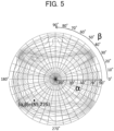
- Rotation angles of ⁇ and ⁇ are displayed in parentheses as with ( ⁇ , ⁇ ), respectively.
- the center of a circle is (0, 0), and the direction of 3 o'clock is (90, 0).
- a display method of the pole figure is illustrated in Fig. 5 .
- diffraction intensities of a crystal orientation group of LD// ⁇ 111> is detected by the combination of ⁇ and ⁇ that is represented by a + mark in Fig. 6 .
- diffraction intensities of a crystal orientation group of LD// ⁇ 100> is detected by the combination of ⁇ and ⁇ that is represented by a ⁇ mark in Fig. 6 .
- a table in which the angles of ⁇ and ⁇ are set to two axes is illustrated in Fig. 7 .
- a sum of the diffraction intensities of the crystal orientation group of LD// ⁇ 111> was K111, and a sum of the diffraction intensities of the crystal orientation group of LD// ⁇ 100> was K100.
- a peak intensity ratio H (K100/K111) increases as the crystal orientation group of LD// ⁇ 100> increases and the crystal orientation group of LD// ⁇ 111> decreases.
- H is 0.15 or more, and H is more preferably 0.30 or more, and is even more preferably 0.45 or more.
- An upper limit of H is not particularly limited, but is 6 or less.
- the crystal orientation of LD// ⁇ 111> is the factor of decreasing the bending workability of the aluminum alloy material subjected to strong deformation. Therefore, in the texture of the primary surface, it is preferable to decrease the crystal orientation of LD// ⁇ 111> and to increase the ratio of the crystal orientation of LD// ⁇ 100>, from the viewpoint of improving the bending workability.
- the tensile strength is a value that is measured on the basis of JIS Z2241:2011. The detailed measurement condition will be described in the section of Examples described below.
- a preferred tensile strength is 220 MPa or more.
- Such a tensile strength is greater than 160 MPa to 200 MPa that is a tensile strength of aluminum A1350 for conduction shown in ASTM INTERNATIONAL by 10% or more. (Standard Name: B230/B230M-07).
- a preferred tensile strength of the present invention is 260 MPa or more, and a more preferred tensile strength is 300 MPa or more. Further, an even more preferred tensile strength is 340 MPa or more. Such a tensile strength is greater than 305 MPa to 330 MPa that is a tensile strength of a 6000-based aluminum alloy A6201 shown in ASTM INTERNATIONAL. (Standard Name: B398/B398M-14). The most preferred tensile strength is 380 MPa or more.
- the Vickers hardness (HV) is a value that is measured on the basis of JIS Z2244:2009. The detailed measurement condition will be described in the section of Examples described below. Note that, in the case of measuring a Vickers hardness (HV) of a product that has been already a part, the product is disassembled, and a cross section is subjected to mirror polishing, and thus, the cross section can also be measured.
- the Vickers hardness HV is preferably 60 or more. Such HV is greater than 54 that is HV of aluminum A1350 for conduction shown in ASTM INTERNATIONAL by 10% or more.
- preferred HV of the present invention is 70 or more, and more preferred HV is 80 or more. Even more preferred HV is 90 or more.
- a tensile strength is greater than 85 that is tensile strength of a 6000-based aluminum alloy A6201 shown ASTM INTERNATIONAL.
- the most preferred HV is 100 or more.
- an upper limit of the Vickers hardness (HV) of the aluminum alloy material of the present invention is not particularly limited, but for example, is 250.
- the bending workability was more excellent and was represented by a 02 mark, and in a case where the bending was capable of being performed at a radius of half the wire diameter, the bending workability was most excellent and was represented by a 03 mark.
- a preferred conductivity is different in accordance with an application or a strength band.
- conduction is a basic function, and thus, it is preferable that the conductivity is 55%IACS or more. It is more preferable that the conductivity is 57%IACS or more.
- mechanical properties are a basic function, and thus, it is preferable that the conductivity is 45%IACS or more. It is more preferable that the conductivity is 48%IACS or more.
- the aluminum alloy material of the present invention is a bare material, that is, sufficiently has properties such as a tensile strength, a Vickers hardness, bending workability, and conductivity by itself.
- the aluminum alloy material of the present invention is not only used as the bare material, but also has excellent joining properties in the case of being covered with other metals by a method such as plating or clad, and exhibits an effect of making excellent strength, excellent bending workability, and excellent electric conductive properties compatible as with the case of the bare material.
- the type of metal for covering includes Cu, Ni, Ag, Pd, Au, Sn, and the like. There is an effect of reducing contact resistance, of improving corrosion resistance, or the like.
- a coverage is preferably approximately 25% of the entire area, in the cross section perpendicular to the longitudinal direction. This is because in a case where the coverage is excessively large, an effect of decreasing weight is reduced.
- the coverage is preferably 15% or less, is more preferably 10% or less, and is even more preferably 5% or less.
- the metal for covering is dissolved with an acid such that the surface of the aluminum alloy is exposed, and then, the crystal orientation is measured as with a bare aluminum alloy.
- the metal for covering reacts with the aluminum alloy that is the base material by working heat generation, and thus, an intermetallic compound may be formed. Accordingly, for example, a method such as decreasing a wire drawing working speed to a 50 m/min or less or increasing the ability of cooling a workpiece by forcibly cooling an antifriction is required.
- the aluminum alloy material of the present invention can be used in all applications in which an iron-based material, a copper-based material, and an aluminum-based material are used.
- the aluminum alloy material can be preferably used as a conductive member such as an electric wire or a cable, a battery member such as a mesh or a net for a current collector, a fastening part such as a screw, a bolt, or a rivet, a spring part such as a coil spring, a spring member for electric contact such as a connector or a terminal, a structural part such as a shaft or a frame, a guide wire, a bonding wire for a semiconductor, a winding wire used in a power generator or a motor, and the like.
- the conductive member include a power wire such as an overhead transmission electric wire, OPGW, an underground electric wire, and an underwater cable, an electric wire for communication such as a telephone cable or a coaxial cable, an electric wire for a device such as a wired drone cable, a cabtire cable, an EV/HEV charging cable, a twisted cable for offshore wind power generation, an elevator cable, an umbilical cable, a robot cable, a train cable, or a trolley wire, an electric wire for transportation such as an automobile wire harness, a marine electric wire, or an airplane electric wire, a bus bar, a lead frame, a flexible flat cable, a conductor rod, an antenna, a connector, a terminal, a cable braid, a cleaner cable, a conductor for a wearable device, and the like.
- a power wire such as an overhead transmission electric wire, OPGW, an underground electric wire, and an underwater cable
- an electric wire for communication such as a telephone cable or a coaxial cable
- the twisted wire may be obtained by mixing the aluminum alloy of the present invention with a versatile conductor such as copper or aluminum.
- the battery member include an electrode of a solar battery, an electrode of a lithium ion battery, and the like.
- the structural part (member) include a scaffold in a construction site, a conveyor mesh belt, a metal fiber for clothing, a chain mail, a fence, an insect repellent net, a zipper, a fastener, a clip, aluminum wool, a bicycle part such as a brake wire or a spoke, a reinforcement wire for reinforced glass, a pipe seal, metal packing, a protection reinforcement material for a cable, a core metal for a fan belt, a wire for driving an actuator, a chain, a hanger, a mesh for soundproofing, a shelf, a strength reinforcement wire for a high-pressure tank such as a hydrogen tank, a tension member for a cable, a mesh for screen printing, and the like.
- a high-pressure tank such as a hydrogen tank, a tension member for a cable, a mesh for screen printing, and the like.
- the fastening part (member) include a set screw, a staple, a pushpin, and the like.
- the spring part (member) include a spring electrode, a terminal, a connector, a spring for a semiconductor probe, a plate spring, a power spring, and the like.
- the aluminum alloy material is also preferable as a resin-based material, a plastic material, and a metal fiber that is added in order to impart electric conductive properties to cloth or the like or to control a strength or an elastic modulus.
- the aluminum alloy material is also preferable as a consumer member or a medical member such as an eyeglass frame, a watch belt, a pen point of a fountain pen, a fork, a helmet, or an injection needle.
- the aluminum alloy material according to the present invention may be used by being suitably combined or mixed with another material.
- each rod material of 10 mm ⁇ , having an alloy composition shown in Table 1 was prepared.
- each aluminum alloy wire rod (0.21 mm ⁇ to 1.93 mm ⁇ ) was prepared by using each of the rod materials, in a manufacturing condition shown in Table 1.
- the temper annealing [3] was performed in a condition of a treatment temperature of 100°C and a retention time of 36 hours, after the manufacturing condition A.
- the temper annealing [3] was performed in a condition of a treatment temperature of 100°C and a retention time of 36 hours, after the manufacturing condition B.
- the temper annealing [3] was performed in a condition of a treatment temperature of 100°C and a retention time of 36 hours, after the manufacturing condition C.
- an aluminum wire rod (0.24 mm ⁇ ) was prepared by using a rod material of 10 mm ⁇ , containing 99.99 mass%-Al, in a manufacturing condition shown in Table 1.
- each aluminum alloy wire rod (0.07 mm ⁇ to 2.0 mm ⁇ ) was prepared by using each rod material of 10 mm ⁇ , having an alloy composition shown in Table 1, in a manufacturing condition shown in Table 1.
- the stabilization heat treatment in the manufacturing condition B was not performed, and wire drawing working having a total working degree of 7.7 was performed. Note that, the temper annealing [3] was not performed.
- the stabilization heat treatment in the manufacturing condition B was performed at 200°C for 5 hours.
- Aluminum having a purity of 99.95 mass%, magnesium having a purity of 99.95 mass%, silicon having a purity of 99.99 mass%, iron having a purity of 99.95 mass%, and each predetermined amount of Ti and B were put in a graphite crucible, and were stirred and melted at 720°C by highfrequency induction heating, and thus, a molten metal having an alloy composition of Al-0.06Si-0.24Fe-0.21Cu-0.11Mg (mass%) was manufactured, and was moved to a container provided with a graphite die, and a wire of 10 mm ⁇ , having a length of 100 mm, was continuously cast at a casting speed of approximately 300 mm/minute through the graphite die subjected to water cooling.
- a recrystallization temperature was 300°C.
- preheating was performed at 250°C for 2 hours.
- a first wire drawing treatment having a working rate of 29% (a working degree of 0.34) was performed.
- a recrystallization temperature was 300°C.
- a primary heat treatment was performed at 260°C for 2 hours. After that, the wire passed through a wire drawing die subjected to water cooling at a drawing speed of 500 mm/minute, and thus, a second wire drawing treatment having a working degree of 9.3 was performed.
- a recrystallization temperature was 280°C.
- a secondary heat treatment was performed at 220°C for 1 hour, and thus, an aluminum alloy wire rod (0.08 mm ⁇ ) was obtained.
- the wire drawing was performed in a condition in which a die half-angle was 5°, and a working rate per one pass was 16%.
- An alloy composition was measured by an emission spectroscopic analysis method, on the basis of JIS H1305:2005. Note that, the measurement was performed by using an emission spectroscopic analysis device (manufactured by Hitachi High-Tech Science Corporation).
- a metal structure was observed by using a transmission electron microscope (JEM-2100PLUS, manufactured by JEOL Ltd.), in accordance with transmission electron microscopy (TEM) observation.
- the observation was performed at an acceleration voltage of 200 kV.
- a cross section parallel to a longitudinal direction of the wire rod (the wire drawing direction X) was cut into a thickness of 100 nm ⁇ 20 nm by a focused ion beam (FIB), and was finished with ion milling.
- FIB focused ion beam
- a difference in the contrast was recognized as the crystal orientation and a boundary in which the contrast was discontinuous different was recognized as the crystal grain boundary, by using gray contrast.
- an observation visual field was (15 to 40) ⁇ m ⁇ (15 to 40) pm, and in the cross section described above, the observation was performed at a position in the vicinity of the middle between the center and a surface layer (a position on the center side of approximately 1/4 of the wire diameter from the surface layer side), on a line corresponding to a wire diameter direction (a direction perpendicular to the longitudinal direction).
- the observation visual field was suitably adjusted in accordance with the size of the crystal grains.
- the cross section parallel to the longitudinal direction of the wire rod the wire drawing direction X
- the presence or absence of a fibrous metal structure was determined from an image that was photographed in the TEM observation.
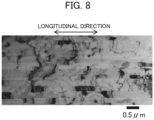
- FIG. 8 is a part of a TEM image of the cross section parallel to the longitudinal direction of the wire rod of Example 28 of the present invention (the wire drawing direction X), that was photographed in the TEM observation.
- the fibrous metal structure was evaluated as "Present”.
- arbitrary 100 grains were selected from the crystal grains, the dimension of each of the crystal grains in a direction perpendicular to the longitudinal direction and the dimension of each of the crystal grains in a direction parallel to the longitudinal direction were measured, and an aspect ratio of the crystal grains was calculated.
- an average value was calculated from the total number of observed crystal grains. Note that, in a case where the observed crystal grains were obviously larger than 400 nm, the number of selected crystal grains to be measured for each dimension was reduced and each average value thereof was calculated. In addition, in a case where the dimension of the crystal grains in the direction parallel to the longitudinal direction was obviously 10 times or more the dimension of the crystal grains in the direction perpendicular to the longitudinal direction, the aspect ratio was determined to be uniformly 10 or more.
- a tensile test was performed by using a precision universal testing machine (manufactured by Shimadzu Corporation), on the basis of JIS Z2241:2001, and a tensile strength (MPa) was measured. Note that, the test described above was performed in a condition in which a distance between grades was 100 mm and a deformation speed was 10 mm/minute. In this example, in the wire rod before heating, a tensile strength of 220 MPa or more was an acceptable level.
- a Vickers hardness (HV) was measured by using a fine hardness testing machine HM-125 (manufactured by Akashi Co., Ltd. (currently, Mitutoyo Corporation)), on the basis of JIS Z 2244:2009. At this time, a test force was 0.1 kgf and a retention time was 15 seconds.
- HV Vickers hardness
- the bending workability was more excellent and was represented by a 02 mark, and in a case where the bending was capable of being performed at a radius of half the wire diameter, the bending workability was most excellent and was represented by a 03 mark.
- a conductivity was measured at 20 ⁇ 1°C by a four-terminal method.
- the conduction was a basic function, and thus, a conductivity of 55%IACS or more was an acceptable level.
- mechanical properties were a basic function, and thus, a conductivity of 45%IACS or more was an acceptable level.
- a thermal conductivity was proportional to the conductivity, and thus, the determination of excellent or poor was substituted by the evaluation of the conductivity.
- the aluminum alloy wire rods of Examples 1 to 33 of the present invention had the alloy composition in the proper range of the present invention, had the fibrous metal structure in which the crystal grains extended in one direction, had the average value of the dimensions of the crystal grains in the direction perpendicular to the longitudinal direction of 800 nm or less, and had the crystal orientation distribution in which the ratio H of K100 to K111 was 0.15 or more.
- Fig. 8 is the TEM image of the cross section parallel to the wire drawing direction of the aluminum alloy wire rod of Example 28 of the present invention. Note that, the same metal structure as that in Fig. 8 was also checked in the cross section parallel to the longitudinal direction, in the aluminum alloy wire rods according to Examples 1 to 27 and 29 to 33 of the present invention.
- the tensile strength was 220 MPa or more
- the Vickers hardness HV was 60 or more
- the W bending workability was excellent
- the conductivity was also excellent.
- the composition was out of the proper range of the present invention, the average value of the dimensions t of the crystal grains in the direction perpendicular to the longitudinal direction was greater than 400 nm, and the ratio H of K100 to K111 was also less than 0.15, and thus, all of the tensile strength, the Vickers hardness, and the W bending workability were lower than the acceptable level.
- the content of Si was greater than the proper range of the present invention, and thus, the conductivity was lower than the acceptable level.
- the content of Fe was greater than the proper range of the present invention, and thus, the disconnection occurred at a high level, and a test piece was not capable of being prepared by the wire drawing working.
- the content of Cu was greater than the proper range of the present invention, and thus, the conductivity was lower than the acceptable level.
- the content of Mg was greater than the proper range of the present invention, and thus, the conductivity was lower than the acceptable level.
- a total content of Ti, B, and Mn was greater than the proper range of the present invention, and thus, the conductivity was lower than the acceptable level.
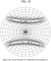
- Example 28 of the present invention the crystal orientation group of LD// ⁇ 100> was developed, and the crystal orientation group of LD// ⁇ 111> was also observed. On the other hand, it is found that in Comparative Example 9, only the crystal orientation group of LD// ⁇ 111> is strongly integrated.
Landscapes
- Chemical & Material Sciences (AREA)
- Engineering & Computer Science (AREA)
- Materials Engineering (AREA)
- Mechanical Engineering (AREA)
- Metallurgy (AREA)
- Organic Chemistry (AREA)
- Physics & Mathematics (AREA)
- Thermal Sciences (AREA)
- Crystallography & Structural Chemistry (AREA)
- Conductive Materials (AREA)
- Non-Insulated Conductors (AREA)
- Insulated Conductors (AREA)
- Cell Electrode Carriers And Collectors (AREA)
Claims (10)
- Matériau en alliage d'aluminium (1) présentant une composition d'alliage comprenant au moins un parmi de 0,05 % en masse à 1,50 % en masse de Fe, de 0,01 % en masse à 0,15 % en masse de Si, de 0,01 % en masse à 0,3 % en masse de Cu et de 0,01 % en masse à 1,5 % en masse de Mg, et facultativement un total de 0,30 % en masse ou moins d'un ou plusieurs sélectionnés dans le groupe consistant en : RE, Ag, Ni, Mn, Cr, Zr, Ti et B, le reste étant Al et des impuretés inévitables,dans lequel le matériau en alliage d'aluminium (1) présente une structure métallique fibreuse dans laquelle des grains cristallins (10) s'étendent dans une direction,dans une section transversale parallèle à l'une direction, une valeur moyenne de dimensions des grains cristallins (10) dans une direction perpendiculaire à une direction longitudinale des grains cristallins (10) est de 800 nm ou moins, etune surface primaire du matériau en alliage d'aluminium (1) présente une distribution d'orientation cristalline dans laquelle, lorsque K100 est une somme d'intensités de diffraction résultant de cristaux dans lesquels <100> est orienté dans le sens longitudinal, K111 est une somme d'intensités de diffraction résultant de cristaux dans lesquels <111> est orienté dans le sens longitudinal, et H est un rapport (K100/K111) de K100 sur K111, le rapport (H) est de 0,15 ou plus tel que déterminé par un procédé de figure de pôle à rayons X, etdans lequel la surface primaire est une surface du matériau en alliage d'aluminium (1) qui est parallèle à une direction de travail, et indique une surface qui est directement en contact avec un outil et qui est soumise à une rétreinte.
- Matériau en alliage d'aluminium (1) présentant la composition d'alliage selon la revendication 1, dans lequel la composition d'alliage comprend un total de 0,30 % en masse ou moins d'un ou de plusieurs éléments sélectionnés dans le groupe consistant en : RE, Ag, Ni, Mn, Cr, Zr, Ti et B.
- Matériau en alliage d'aluminium (1) selon la revendication 1 ou 2,dans lequel une dureté Vickers (HV) est de 60 à 250, etdans lequel la dureté Vickers (HV) est une valeur qui est mesurée sur la base de la norme JIS Z2244:2009 selon le procédé décrit dans la description.
- Matériau en alliage d'aluminium selon l'une quelconque des revendications 1 à 3,
dans lequel la surface est couverte d'un ou plusieurs de métaux ou d'alliages sélectionnés dans le groupe consistant en : Cu, Ni, Ag, Au, Pd et Sn. - Élément conducteur utilisant le matériau en alliage d'aluminium (1) selon l'une quelconque des revendications 1 à 4.
- Élément de batterie utilisant le matériau en alliage d'aluminium (1) selon l'une quelconque des revendications 1 à 4.
- Pièce de fixation utilisant le matériau en alliage d'aluminium (1) selon l'une quelconque des revendications 1 à 4.
- Pièce de ressort utilisant le matériau en alliage d'aluminium (1) selon l'une quelconque des revendications 1 à 4.
- Pièce structurale utilisant le matériau en alliage d'aluminium (1) selon l'une quelconque des revendications 1 à 4.
- Câble électrique sous caoutchouc utilisant le matériau en alliage d'aluminium (1) selon l'une quelconque des revendications 1 à 4.
Applications Claiming Priority (2)
| Application Number | Priority Date | Filing Date | Title |
|---|---|---|---|
| JP2018059187 | 2018-03-27 | ||
| PCT/JP2019/010971 WO2019188451A1 (fr) | 2018-03-27 | 2019-03-15 | Matériau d'alliage d'aluminium et élément conducteur, élément de batterie, partie de fixation, partie à ressort et partie structurale utilisant le matériau d'alliage d'aluminium |
Publications (4)
| Publication Number | Publication Date |
|---|---|
| EP3778944A1 EP3778944A1 (fr) | 2021-02-17 |
| EP3778944A4 EP3778944A4 (fr) | 2021-12-29 |
| EP3778944C0 EP3778944C0 (fr) | 2024-09-25 |
| EP3778944B1 true EP3778944B1 (fr) | 2024-09-25 |
Family
ID=68058833
Family Applications (1)
| Application Number | Title | Priority Date | Filing Date |
|---|---|---|---|
| EP19775968.1A Active EP3778944B1 (fr) | 2018-03-27 | 2019-03-15 | Matériau d'alliage d'aluminium et élément conducteur, élément de batterie, partie de fixation, partie à ressort et partie structurale utilisant le matériau d'alliage d'aluminium |
Country Status (6)
| Country | Link |
|---|---|
| US (1) | US11236410B2 (fr) |
| EP (1) | EP3778944B1 (fr) |
| JP (1) | JP6599062B1 (fr) |
| KR (1) | KR102520007B1 (fr) |
| CN (1) | CN111511940B (fr) |
| WO (1) | WO2019188451A1 (fr) |
Families Citing this family (9)
| Publication number | Priority date | Publication date | Assignee | Title |
|---|---|---|---|---|
| EP3730639A4 (fr) * | 2017-12-22 | 2021-07-28 | NHK Spring Co., Ltd. | Alliage d'aluminium, ressort en alliage d'aluminium et élément de fixation en alliage d'aluminium |
| JP6858310B2 (ja) * | 2019-01-31 | 2021-04-14 | 古河電気工業株式会社 | アルミニウム合金材およびこれを用いた、導電部材、電池用部材、締結部品、バネ用部品、構造用部品、キャブタイヤケーブル |
| CN111816353B (zh) * | 2020-07-24 | 2021-10-08 | 广东欣意电缆有限公司 | 一种稀土高铁铝合金电缆及其制备方法 |
| JP2022063563A (ja) * | 2020-10-12 | 2022-04-22 | 東洋アルミニウム株式会社 | アルミニウム合金箔及びその製造方法 |
| CN113061789B (zh) * | 2021-02-02 | 2022-03-08 | 重庆材料研究院有限公司 | 轻质超宽防雷击用含铜铝网及其制备方法 |
| CN115249811A (zh) * | 2021-04-25 | 2022-10-28 | 恒大新能源技术(深圳)有限公司 | 铝箔集流体及其制备方法、二次电池 |
| CN114737089A (zh) * | 2022-05-24 | 2022-07-12 | 国网智能电网研究院有限公司 | 一种铝合金材料及其制备方法与应用 |
| CN115976376B (zh) * | 2022-12-21 | 2024-09-13 | 佛山市坤旺有色金属有限公司 | 一种用于铲齿散热器的铝型材及其挤压方法 |
| CN116297459B (zh) * | 2023-04-10 | 2025-09-23 | 首钢智新迁安电磁材料有限公司 | 快速测量取向硅钢成品晶粒取向的方法 |
Family Cites Families (22)
| Publication number | Priority date | Publication date | Assignee | Title |
|---|---|---|---|---|
| JP2628235B2 (ja) | 1991-04-09 | 1997-07-09 | 三菱電線工業株式会社 | 導電用高耐熱性アルミニウム合金線の製造方法 |
| JPH05331585A (ja) | 1992-05-27 | 1993-12-14 | Honda Motor Co Ltd | 高強度Al合金 |
| JP3654466B2 (ja) | 1995-09-14 | 2005-06-02 | 健司 東 | アルミニウム合金の押出加工法及びそれにより得られる高強度、高靭性のアルミニウム合金材料 |
| JP3475236B2 (ja) | 1999-11-01 | 2003-12-08 | 独立行政法人物質・材料研究機構 | アルミニウム合金展伸材の製造方法 |
| JP4398117B2 (ja) | 2001-07-09 | 2010-01-13 | 株式会社神戸製鋼所 | 微細組織を有する構造用アルミニウム合金板およびその製造方法 |
| JP2006322064A (ja) | 2005-04-19 | 2006-11-30 | Furukawa Electric Co Ltd:The | 高成形性アルミニウム材料 |
| JP5360547B2 (ja) | 2009-01-07 | 2013-12-04 | 国立大学法人信州大学 | 金属粒子と炭素粉末の複合化方法、および金属・炭素複合材料の製造方法 |
| JP5846360B2 (ja) * | 2011-08-25 | 2016-01-20 | 古河電気工業株式会社 | アルミニウム合金導体 |
| JP6696895B2 (ja) * | 2014-03-31 | 2020-05-20 | 古河電気工業株式会社 | 圧延銅箔、圧延銅箔の製造方法、フレキシブルフラットケーブル、フレキシブルフラットケーブルの製造方法 |
| WO2015182777A1 (fr) * | 2014-05-29 | 2015-12-03 | 古河電気工業株式会社 | Matériau en feuille d'alliage de cuivre, son procédé de production et composant électrique/électronique comprenant ledit matériau en feuille d'alliage de cuivre |
| CN106460099B (zh) * | 2014-05-30 | 2020-03-17 | 古河电气工业株式会社 | 铜合金板材、由铜合金板材构成的连接器和铜合金板材的制造方法 |
| JP5950249B2 (ja) * | 2014-08-08 | 2016-07-13 | 住友電気工業株式会社 | 銅合金線、銅合金撚線、被覆電線、及び端子付き電線 |
| EP3199654B1 (fr) * | 2014-09-22 | 2019-08-14 | Furukawa Electric Co. Ltd. | Fil en alliage d'aluminium ainsi que procédé de fabrication de celui-ci, fil toronné en alliage d'aluminium, fil électrique revêtu, et faisceau de câble |
| EP3228719B1 (fr) * | 2014-12-05 | 2021-03-03 | Furukawa Electric Co., Ltd. | Fil machine en alliage d'aluminium, fil toronné en alliage d'aluminium, fil isolé, faisceau de fils et procédé de production du fil machine en alliage d'aluminium |
| WO2016088887A1 (fr) | 2014-12-05 | 2016-06-09 | 古河電気工業株式会社 | Matériau de fil en alliage d'aluminium, fil toronné en alliage d'aluminium, fil électrique gainé, faisceau électrique et procédé permettant de produire un matériau de fil en alliage d'aluminium |
| WO2016088888A1 (fr) * | 2014-12-05 | 2016-06-09 | 古河電気工業株式会社 | Fil machine en alliage d'aluminium, conducteur toronné en alliage d'aluminium, conducteur gainé, et faisceau de câbles, et procédé de fabrication de fil machine en alliage d'aluminium |
| JP6102987B2 (ja) * | 2015-06-12 | 2017-03-29 | 株式会社オートネットワーク技術研究所 | アルミニウム合金線、アルミニウム合金撚線、被覆電線およびワイヤーハーネス |
| JP6712887B2 (ja) | 2016-03-31 | 2020-06-24 | 古河電気工業株式会社 | アルミニウム合金線材、アルミニウム合金撚線、被覆電線およびワイヤーハーネス |
| EP3486341B1 (fr) * | 2016-07-13 | 2023-05-10 | Furukawa Electric Co., Ltd. | Matériau en alliage d'aluminium et élément conducteur, élément de batterie, composant de fixation, composant de ressort et composant structurel contenant le matériau en alliage d'aluminium |
| EP3486342B1 (fr) | 2016-07-13 | 2023-08-30 | Furukawa Electric Co., Ltd. | Matériau d'alliage d'aluminium, et élément conducteur d'électricité, élément de batterie, composant de fixation et composant structural le mettant en uvre |
| KR102489191B1 (ko) | 2017-03-29 | 2023-01-16 | 후루카와 덴키 고교 가부시키가이샤 | 알루미늄 합금재 그리고 이것을 사용한 도전 부재, 전지용 부재, 체결 부품, 스프링용 부품 및 구조용 부품 |
| CN107475572A (zh) | 2017-08-16 | 2017-12-15 | 吴振江 | 超细铝合金线材及其制造方法以及相应的衍生品 |
-
2019
- 2019-03-15 EP EP19775968.1A patent/EP3778944B1/fr active Active
- 2019-03-15 JP JP2019533255A patent/JP6599062B1/ja active Active
- 2019-03-15 WO PCT/JP2019/010971 patent/WO2019188451A1/fr not_active Ceased
- 2019-03-15 CN CN201980006795.8A patent/CN111511940B/zh active Active
- 2019-03-15 KR KR1020207016692A patent/KR102520007B1/ko active Active
- 2019-03-15 US US16/979,654 patent/US11236410B2/en active Active
Also Published As
| Publication number | Publication date |
|---|---|
| KR20200130236A (ko) | 2020-11-18 |
| EP3778944A4 (fr) | 2021-12-29 |
| EP3778944C0 (fr) | 2024-09-25 |
| KR102520007B1 (ko) | 2023-04-10 |
| CN111511940A (zh) | 2020-08-07 |
| JP6599062B1 (ja) | 2019-10-30 |
| US20210025033A1 (en) | 2021-01-28 |
| WO2019188451A1 (fr) | 2019-10-03 |
| CN111511940B (zh) | 2022-05-06 |
| EP3778944A1 (fr) | 2021-02-17 |
| JPWO2019188451A1 (ja) | 2020-04-30 |
| US11236410B2 (en) | 2022-02-01 |
Similar Documents
| Publication | Publication Date | Title |
|---|---|---|
| EP3778944B1 (fr) | Matériau d'alliage d'aluminium et élément conducteur, élément de batterie, partie de fixation, partie à ressort et partie structurale utilisant le matériau d'alliage d'aluminium | |
| EP3778947B1 (fr) | Matériau d'alliage d'aluminium et élément conducteur, élément de batterie, pièce de fixation, pièce de ressort et pièce structurale utilisant un matériau en alliage d'aluminium | |
| EP3587608B1 (fr) | Matériau d'alliage d'aluminium et élément de fixation, élément structurel, élément de ressort, organe conducteur et organe de batterie utilisant le matériau d'alliage d'aluminium | |
| JP6430085B1 (ja) | アルミニウム合金材並びにこれを用いた導電部材、電池用部材、締結部品、バネ用部品および構造用部品 | |
| EP3919643B1 (fr) | Alliage d'aluminium et élément électroconducteur, élément de batterie, composant de fixation, composant à ressort, composant structural et câble gainé en caoutchouc le mettant en oeuvre | |
| EP3486342B1 (fr) | Matériau d'alliage d'aluminium, et élément conducteur d'électricité, élément de batterie, composant de fixation et composant structural le mettant en uvre | |
| KR102589529B1 (ko) | 알루미늄 합금재 및 이를 사용한 편조 실드선, 도전 부재, 전지용 부재, 체결 부품, 스프링용 부품, 구조용 부품 및 캡타이어 케이블 | |
| JP6858310B2 (ja) | アルミニウム合金材およびこれを用いた、導電部材、電池用部材、締結部品、バネ用部品、構造用部品、キャブタイヤケーブル |
Legal Events
| Date | Code | Title | Description |
|---|---|---|---|
| STAA | Information on the status of an ep patent application or granted ep patent |
Free format text: STATUS: THE INTERNATIONAL PUBLICATION HAS BEEN MADE |
|
| PUAI | Public reference made under article 153(3) epc to a published international application that has entered the european phase |
Free format text: ORIGINAL CODE: 0009012 |
|
| STAA | Information on the status of an ep patent application or granted ep patent |
Free format text: STATUS: REQUEST FOR EXAMINATION WAS MADE |
|
| 17P | Request for examination filed |
Effective date: 20200727 |
|
| AK | Designated contracting states |
Kind code of ref document: A1 Designated state(s): AL AT BE BG CH CY CZ DE DK EE ES FI FR GB GR HR HU IE IS IT LI LT LU LV MC MK MT NL NO PL PT RO RS SE SI SK SM TR |
|
| AX | Request for extension of the european patent |
Extension state: BA ME |
|
| DAV | Request for validation of the european patent (deleted) | ||
| DAX | Request for extension of the european patent (deleted) | ||
| A4 | Supplementary search report drawn up and despatched |
Effective date: 20211129 |
|
| RIC1 | Information provided on ipc code assigned before grant |
Ipc: C22C 21/08 20060101ALI20211123BHEP Ipc: H01R 11/00 20060101ALI20211123BHEP Ipc: H01B 1/02 20060101ALI20211123BHEP Ipc: C22F 1/04 20060101ALI20211123BHEP Ipc: C22F 1/00 20060101ALI20211123BHEP Ipc: C22C 21/00 20060101AFI20211123BHEP |
|
| GRAP | Despatch of communication of intention to grant a patent |
Free format text: ORIGINAL CODE: EPIDOSNIGR1 |
|
| STAA | Information on the status of an ep patent application or granted ep patent |
Free format text: STATUS: GRANT OF PATENT IS INTENDED |
|
| RIC1 | Information provided on ipc code assigned before grant |
Ipc: H01R 13/03 20060101ALN20240411BHEP Ipc: C22F 1/04 20060101ALN20240411BHEP Ipc: H01B 1/02 20060101ALI20240411BHEP Ipc: C22C 21/08 20060101ALI20240411BHEP Ipc: C22C 21/00 20060101AFI20240411BHEP |
|
| INTG | Intention to grant announced |
Effective date: 20240429 |
|
| GRAS | Grant fee paid |
Free format text: ORIGINAL CODE: EPIDOSNIGR3 |
|
| GRAA | (expected) grant |
Free format text: ORIGINAL CODE: 0009210 |
|
| STAA | Information on the status of an ep patent application or granted ep patent |
Free format text: STATUS: THE PATENT HAS BEEN GRANTED |
|
| AK | Designated contracting states |
Kind code of ref document: B1 Designated state(s): AL AT BE BG CH CY CZ DE DK EE ES FI FR GB GR HR HU IE IS IT LI LT LU LV MC MK MT NL NO PL PT RO RS SE SI SK SM TR |
|
| REG | Reference to a national code |
Ref country code: GB Ref legal event code: FG4D |
|
| REG | Reference to a national code |
Ref country code: CH Ref legal event code: EP |
|
| REG | Reference to a national code |
Ref country code: DE Ref legal event code: R096 Ref document number: 602019059463 Country of ref document: DE |
|
| REG | Reference to a national code |
Ref country code: IE Ref legal event code: FG4D |
|
| U01 | Request for unitary effect filed |
Effective date: 20241023 |
|
| U07 | Unitary effect registered |
Designated state(s): AT BE BG DE DK EE FI FR IT LT LU LV MT NL PT RO SE SI Effective date: 20241105 |
|
| PG25 | Lapsed in a contracting state [announced via postgrant information from national office to epo] |
Ref country code: NO Free format text: LAPSE BECAUSE OF FAILURE TO SUBMIT A TRANSLATION OF THE DESCRIPTION OR TO PAY THE FEE WITHIN THE PRESCRIBED TIME-LIMIT Effective date: 20241225 |
|
| PG25 | Lapsed in a contracting state [announced via postgrant information from national office to epo] |
Ref country code: GR Free format text: LAPSE BECAUSE OF FAILURE TO SUBMIT A TRANSLATION OF THE DESCRIPTION OR TO PAY THE FEE WITHIN THE PRESCRIBED TIME-LIMIT Effective date: 20241226 |
|
| PG25 | Lapsed in a contracting state [announced via postgrant information from national office to epo] |
Ref country code: RS Free format text: LAPSE BECAUSE OF FAILURE TO SUBMIT A TRANSLATION OF THE DESCRIPTION OR TO PAY THE FEE WITHIN THE PRESCRIBED TIME-LIMIT Effective date: 20241225 |
|
| PG25 | Lapsed in a contracting state [announced via postgrant information from national office to epo] |
Ref country code: RS Free format text: LAPSE BECAUSE OF FAILURE TO SUBMIT A TRANSLATION OF THE DESCRIPTION OR TO PAY THE FEE WITHIN THE PRESCRIBED TIME-LIMIT Effective date: 20241225 Ref country code: NO Free format text: LAPSE BECAUSE OF FAILURE TO SUBMIT A TRANSLATION OF THE DESCRIPTION OR TO PAY THE FEE WITHIN THE PRESCRIBED TIME-LIMIT Effective date: 20241225 Ref country code: GR Free format text: LAPSE BECAUSE OF FAILURE TO SUBMIT A TRANSLATION OF THE DESCRIPTION OR TO PAY THE FEE WITHIN THE PRESCRIBED TIME-LIMIT Effective date: 20241226 |
|
| U20 | Renewal fee for the european patent with unitary effect paid |
Year of fee payment: 7 Effective date: 20250116 |
|
| PG25 | Lapsed in a contracting state [announced via postgrant information from national office to epo] |
Ref country code: IS Free format text: LAPSE BECAUSE OF FAILURE TO SUBMIT A TRANSLATION OF THE DESCRIPTION OR TO PAY THE FEE WITHIN THE PRESCRIBED TIME-LIMIT Effective date: 20250125 |
|
| PG25 | Lapsed in a contracting state [announced via postgrant information from national office to epo] |
Ref country code: SM Free format text: LAPSE BECAUSE OF FAILURE TO SUBMIT A TRANSLATION OF THE DESCRIPTION OR TO PAY THE FEE WITHIN THE PRESCRIBED TIME-LIMIT Effective date: 20240925 |
|
| PG25 | Lapsed in a contracting state [announced via postgrant information from national office to epo] |
Ref country code: ES Free format text: LAPSE BECAUSE OF FAILURE TO SUBMIT A TRANSLATION OF THE DESCRIPTION OR TO PAY THE FEE WITHIN THE PRESCRIBED TIME-LIMIT Effective date: 20240925 |
|
| PG25 | Lapsed in a contracting state [announced via postgrant information from national office to epo] |
Ref country code: CZ Free format text: LAPSE BECAUSE OF FAILURE TO SUBMIT A TRANSLATION OF THE DESCRIPTION OR TO PAY THE FEE WITHIN THE PRESCRIBED TIME-LIMIT Effective date: 20240925 Ref country code: PL Free format text: LAPSE BECAUSE OF FAILURE TO SUBMIT A TRANSLATION OF THE DESCRIPTION OR TO PAY THE FEE WITHIN THE PRESCRIBED TIME-LIMIT Effective date: 20240925 |
|
| PG25 | Lapsed in a contracting state [announced via postgrant information from national office to epo] |
Ref country code: SK Free format text: LAPSE BECAUSE OF FAILURE TO SUBMIT A TRANSLATION OF THE DESCRIPTION OR TO PAY THE FEE WITHIN THE PRESCRIBED TIME-LIMIT Effective date: 20240925 |
|
| PLBE | No opposition filed within time limit |
Free format text: ORIGINAL CODE: 0009261 |
|
| STAA | Information on the status of an ep patent application or granted ep patent |
Free format text: STATUS: NO OPPOSITION FILED WITHIN TIME LIMIT |
|
| 26N | No opposition filed |
Effective date: 20250626 |
|
| PG25 | Lapsed in a contracting state [announced via postgrant information from national office to epo] |
Ref country code: MC Free format text: LAPSE BECAUSE OF FAILURE TO SUBMIT A TRANSLATION OF THE DESCRIPTION OR TO PAY THE FEE WITHIN THE PRESCRIBED TIME-LIMIT Effective date: 20240925 |
|
| REG | Reference to a national code |
Ref country code: CH Ref legal event code: H13 Free format text: ST27 STATUS EVENT CODE: U-0-0-H10-H13 (AS PROVIDED BY THE NATIONAL OFFICE) Effective date: 20251023 |
|
| GBPC | Gb: european patent ceased through non-payment of renewal fee |
Effective date: 20250315 |
|
| PG25 | Lapsed in a contracting state [announced via postgrant information from national office to epo] |
Ref country code: GB Free format text: LAPSE BECAUSE OF NON-PAYMENT OF DUE FEES Effective date: 20250315 |
|
| PG25 | Lapsed in a contracting state [announced via postgrant information from national office to epo] |
Ref country code: HR Free format text: LAPSE BECAUSE OF FAILURE TO SUBMIT A TRANSLATION OF THE DESCRIPTION OR TO PAY THE FEE WITHIN THE PRESCRIBED TIME-LIMIT Effective date: 20240925 |
|
| PG25 | Lapsed in a contracting state [announced via postgrant information from national office to epo] |
Ref country code: CH Free format text: LAPSE BECAUSE OF NON-PAYMENT OF DUE FEES Effective date: 20250331 |
|
| PG25 | Lapsed in a contracting state [announced via postgrant information from national office to epo] |
Ref country code: IE Free format text: LAPSE BECAUSE OF NON-PAYMENT OF DUE FEES Effective date: 20250315 |
|
| U20 | Renewal fee for the european patent with unitary effect paid |
Year of fee payment: 8 Effective date: 20260209 |