EP3779115B1 - Coupleur d'outil à connexion filetée pour un entraînement supérieur - Google Patents
Coupleur d'outil à connexion filetée pour un entraînement supérieur Download PDFInfo
- Publication number
- EP3779115B1 EP3779115B1 EP20197429.2A EP20197429A EP3779115B1 EP 3779115 B1 EP3779115 B1 EP 3779115B1 EP 20197429 A EP20197429 A EP 20197429A EP 3779115 B1 EP3779115 B1 EP 3779115B1
- Authority
- EP
- European Patent Office
- Prior art keywords
- stem
- drive
- tool
- couplings
- coupling
- Prior art date
- Legal status (The legal status is an assumption and is not a legal conclusion. Google has not performed a legal analysis and makes no representation as to the accuracy of the status listed.)
- Active
Links
Images


Classifications
-
- F—MECHANICAL ENGINEERING; LIGHTING; HEATING; WEAPONS; BLASTING
- F16—ENGINEERING ELEMENTS AND UNITS; GENERAL MEASURES FOR PRODUCING AND MAINTAINING EFFECTIVE FUNCTIONING OF MACHINES OR INSTALLATIONS; THERMAL INSULATION IN GENERAL
- F16D—COUPLINGS FOR TRANSMITTING ROTATION; CLUTCHES; BRAKES
- F16D1/00—Couplings for rigidly connecting two coaxial shafts or other movable machine elements
- F16D1/10—Quick-acting couplings in which the parts are connected by simply bringing them together axially
-
- F—MECHANICAL ENGINEERING; LIGHTING; HEATING; WEAPONS; BLASTING
- F16—ENGINEERING ELEMENTS AND UNITS; GENERAL MEASURES FOR PRODUCING AND MAINTAINING EFFECTIVE FUNCTIONING OF MACHINES OR INSTALLATIONS; THERMAL INSULATION IN GENERAL
- F16D—COUPLINGS FOR TRANSMITTING ROTATION; CLUTCHES; BRAKES
- F16D1/00—Couplings for rigidly connecting two coaxial shafts or other movable machine elements
- F16D1/06—Couplings for rigidly connecting two coaxial shafts or other movable machine elements for attachment of a member on a shaft or on a shaft-end
- F16D1/08—Couplings for rigidly connecting two coaxial shafts or other movable machine elements for attachment of a member on a shaft or on a shaft-end with clamping hub; with hub and longitudinal key
- F16D1/09—Couplings for rigidly connecting two coaxial shafts or other movable machine elements for attachment of a member on a shaft or on a shaft-end with clamping hub; with hub and longitudinal key with radial clamping due to axial loading of at least one pair of conical surfaces
- F16D1/092—Couplings for rigidly connecting two coaxial shafts or other movable machine elements for attachment of a member on a shaft or on a shaft-end with clamping hub; with hub and longitudinal key with radial clamping due to axial loading of at least one pair of conical surfaces the pair of conical mating surfaces being provided on the coupled hub and shaft
-
- E—FIXED CONSTRUCTIONS
- E21—EARTH OR ROCK DRILLING; MINING
- E21B—EARTH OR ROCK DRILLING; OBTAINING OIL, GAS, WATER, SOLUBLE OR MELTABLE MATERIALS OR A SLURRY OF MINERALS FROM WELLS
- E21B17/00—Drilling rods or pipes; Flexible drill strings; Kellies; Drill collars; Sucker rods; Cables; Casings; Tubings
- E21B17/02—Couplings; joints
- E21B17/03—Couplings; joints between drilling rod or pipe and drill motor or surface drive, e.g. between drilling rod and hammer
-
- E—FIXED CONSTRUCTIONS
- E21—EARTH OR ROCK DRILLING; MINING
- E21B—EARTH OR ROCK DRILLING; OBTAINING OIL, GAS, WATER, SOLUBLE OR MELTABLE MATERIALS OR A SLURRY OF MINERALS FROM WELLS
- E21B19/00—Handling rods, casings, tubes or the like outside the borehole, e.g. in the derrick; Apparatus for feeding the rods or cables
- E21B19/16—Connecting or disconnecting pipe couplings or joints
-
- E—FIXED CONSTRUCTIONS
- E21—EARTH OR ROCK DRILLING; MINING
- E21B—EARTH OR ROCK DRILLING; OBTAINING OIL, GAS, WATER, SOLUBLE OR MELTABLE MATERIALS OR A SLURRY OF MINERALS FROM WELLS
- E21B3/00—Rotary drilling
- E21B3/02—Surface drives for rotary drilling
- E21B3/022—Top drives
-
- F—MECHANICAL ENGINEERING; LIGHTING; HEATING; WEAPONS; BLASTING
- F16—ENGINEERING ELEMENTS AND UNITS; GENERAL MEASURES FOR PRODUCING AND MAINTAINING EFFECTIVE FUNCTIONING OF MACHINES OR INSTALLATIONS; THERMAL INSULATION IN GENERAL
- F16D—COUPLINGS FOR TRANSMITTING ROTATION; CLUTCHES; BRAKES
- F16D1/00—Couplings for rigidly connecting two coaxial shafts or other movable machine elements
- F16D1/10—Quick-acting couplings in which the parts are connected by simply bringing them together axially
- F16D1/108—Quick-acting couplings in which the parts are connected by simply bringing them together axially having retaining means rotating with the coupling and acting by interengaging parts, i.e. positive coupling
- F16D1/112—Quick-acting couplings in which the parts are connected by simply bringing them together axially having retaining means rotating with the coupling and acting by interengaging parts, i.e. positive coupling the interengaging parts comprising torque-transmitting surfaces, e.g. bayonet joints
-
- F—MECHANICAL ENGINEERING; LIGHTING; HEATING; WEAPONS; BLASTING
- F16—ENGINEERING ELEMENTS AND UNITS; GENERAL MEASURES FOR PRODUCING AND MAINTAINING EFFECTIVE FUNCTIONING OF MACHINES OR INSTALLATIONS; THERMAL INSULATION IN GENERAL
- F16D—COUPLINGS FOR TRANSMITTING ROTATION; CLUTCHES; BRAKES
- F16D1/00—Couplings for rigidly connecting two coaxial shafts or other movable machine elements
- F16D1/10—Quick-acting couplings in which the parts are connected by simply bringing them together axially
- F16D2001/103—Quick-acting couplings in which the parts are connected by simply bringing them together axially the torque is transmitted via splined connections
Definitions
- Embodiments of the present invention generally relate to equipment and methods for coupling a top drive to one or more tools.
- the coupling may transfer both axial load and torque bi-directionally from the top drive to the one or more tools.
- a wellbore is formed to access hydrocarbon-bearing formations (e.g., crude oil and/or natural gas) or for geothermal power generation by the use of drilling. Drilling is accomplished by utilizing a drill bit that is mounted on the end of a tool string. To drill within the wellbore to a predetermined depth, the tool string is often rotated by a top drive on a drilling rig. After drilling to a predetermined depth, the tool string and drill bit are removed, and a string of casing is lowered into the wellbore. Well construction and completion operations may then be conducted.
- hydrocarbon-bearing formations e.g., crude oil and/or natural gas
- the attachments between the tools and the top drive typically include mechanical, electrical, optical, hydraulic, and/or pneumatic connections, conveying torque, load, data, signals, and/or power.
- the present invention generally relates to equipment and methods for coupling a top drive to one or more tools.
- the coupling may transfer both axial load and torque bi-directionally from the top drive to the one or more tools.
- the present invention relates to a top drive system according to claim 1 and to a method of coupling a drive unit to a tool adapter according to claim 8. Further aspects and preferred embodiments are set out in claim 2 et seq.
- the present invention provides equipment and methods for coupling a top drive to one or more tools.
- the coupling may transfer torque bi-directionally from the top drive to the one or more tools.
- the coupling may provide mechanical, electrical, optical, hydraulic, and/or pneumatic connections.
- the coupling may conveying torque, load, data, signals, and/or power.
- axial loads of tool strings may be expected to be several hundred tons, up to, including, and sometimes surpassing 750 tons.
- Required torque transmission may be tens of thousands of Kg. force-meter, up to, including, and sometimes surpassing 13825.5 kg. force-meter (tens of thousands of foot-pounds, up to, including, and sometimes surpassing 100 thousand foot-pounds).
- Embodiments disclosed herein may provide axial connection integrity, capable of supporting high axial loads, good sealability, resistance to bending, high flow rates, and high flow pressures.
- Embodiments of this disclosure include a reliable method to transfer full bi-directional torque, thereby reducing the risk of accidental breakout of threaded connections along the tool string.
- Embodiments of this disclosure also provide a fast, hands-free method to connect and transfer power from the drive unit to the tool adapter.
- Embodiments provide automatic connection for power and data communications.
- the torque transfer path from the top drive system to the tool string bypasses the threaded connection between the drive unit and the tool adapter. This may allow full bi-directional torque to be applied in the tool string. This compares to systems wherein the torque transfer path proceeds through the threaded connections between the drive unit and the tool adapter which present a risk of backing out the main threaded connection while rotating in the breakout direction.
- Figure 1 illustrates a drilling system 1.
- the drilling system 1 may include a drilling rig derrick 3d on a drilling rig floor 3f.
- drilling rig floor 3f is at the surface of a subsurface formation 7, but the drilling system 1 may also be an offshore drilling unit, having a platform or subsea wellhead in place of or in addition to rig floor 3f.
- the derrick may support a hoist 5, thereby supporting a top drive 4.
- the hoist 5 may be connected to the top drive 4 by threaded couplings.
- the top drive 4 may be connected to a tool string 2.
- top drive 4 may support the axial load of tool string 2.
- the top drive 4 may be connected to the tool string 2 by threaded couplings.
- the rig floor 3f may have an opening through which the tool string 2 extends downwardly into a wellbore 9. At various times, rig floor 3f may support the axial load of tool string 2.
- top drive 4 may provide torque to tool string 2, for example to operate a drilling bit near the bottom of the wellbore 9.
- the tool string 2 may include joints of drill pipe connected together, such as by threaded couplings.
- top drive 4 may provide right hand (RH) torque or left hand (LH) torque to tool string 2, for example to make up or break out joints of drill pipe.
- Power and/or signals may be communicated between top drive 4 and tool string 2.
- pneumatic, hydraulic, electrical, optical, or other power and/or signals may be communicated between top drive 4 and tool string 2.
- the top drive 4 may include a control unit, a drive unit, and a tool adapter.
- the tool adapter may utilize threaded connections.
- the tool adapter may be a combined multi-coupler (CMC) or quick connector to support load and transfer torque with couplings to transfer power (hydraulic, electric, data, and/or pneumatic).
- CMC combined multi-coupler
- quick connector to support load and transfer torque with couplings to transfer power (hydraulic, electric, data, and/or pneumatic).
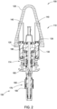
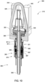
- FIG. 2 illustrates a top drive system 100 (e.g., top drive 4 in Figure 1 ).
- top drive system 100 includes a drive unit 110 and a tool adapter 150.
- the drive unit 110 generally includes a housing 120, becket 125, drive gears 130, motors 140 (e.g., electric or hydraulic motors), first portions of one or more couplings 170, a drive stem 180, and a torque sleeve 190.
- Becket 125 may convey load from the top drive system 100 to the hoist 5.
- Becket 125 may be used with, or replaced by, other load-transfer components.
- Drive gears 130 may couple to motors 140 by way of shaft 135.
- Drive gears 130 may convey torque between the motors 140 and the drive stem 180.
- top drive system 100 includes two drive gears 130 (only one shown in Figure 2 ) and two motors 140. Any number of drive gears 130 and/or motors 140 may be considered to accommodate manufacturing and operational conditions.
- the motors 140 may be fixed relative to the housing 120.
- the drive stem 180 may extend through an interior of torque sleeve 190.
- the tool adapter 150 generally includes a tool stem 160 and second portions of the couplings 170. Couplings 170 may include complementary components disposed in or on drive unit 110 and tool adapter 150.
- the tool stem 160 generally remains below the drive unit 110.
- the tool stem 160 connects the top drive system 100 to the tool string 2.
- the tool stem 160 and drive stem 180 may share a central bore 165 (e.g. providing fluid communication through the top drive system 100 to the tool string 2).
- Couplings 170 may include, for example, threaded couplings, hydraulic couplings, pneumatic couplings, electronic couplings, fiber optic couplings, power couplings, data couplings, and/or signal couplings.
- top drive system 100 may transfer bi-directional torque, load, power, data, and/or signals between the top drive and the tool.
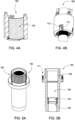
- drive stem 180 may have two gear profiles: drive gear profile 185 and torque gear profile 195.
- Drive gears 130 ( Figure 2 ) may engage drive stem 180 at drive gear profile 185.
- Motors 140 may turn shaft 135, which turns drive gears 130, thereby turning drive gear profile 185 and drive stem 180.
- Drive gear profile 185 may have teeth designed to mesh with the gearing of drive gears 130.
- drive gears 130 and/or drive gear profile 185 may be configured to engage belt drive, chain drive, or other systems that are capable of conveying rotation.
- the drive stem 180 may be encircled by swivel 174, centering ring 181, and/or seal sleeve 182.
- the centering ring 181 may provide rigidity to the connection, for example, resisting bending forces.
- the centering ring 181 may assist in alignment of seals, couplers, and/or data connectors.
- the centering ring 181 may provide for proper alignment between the drive stem 180 and the seal package 163 ( Figure 5B ) of the tool stem 160.
- the fit between the centering ring 181 and the tool stem 160 may control or reduce play between the components, thereby improving the sealing performance.
- the coupling between drive stem 180 and seal sleeve 182 may include a threaded coupling 183 and/or one or more O-rings 184.
- the O-rings 184 may engage the inner diameter of the seal sleeve 182 to reduce or prevent high pressure fluid leakage out of the connection.
- the seal sleeve 182 may be incorporated as a replaceable component of the drive unit 110.
- a portion of the exterior of drive stem 180 may include a threaded coupling 186.
- threaded coupling 186 is disposed between centering ring 181 and torque gear profile 195, but threaded coupling 186 may also be disposed at other locations along the length of drive stem 180.
- threaded coupling 186 may provide a load coupling between drive stem 180 and tool stem 160.
- Threaded coupling 186 may be a heavy-load capacity thread (e.g., stub acme thread).
- torque sleeve 190 may include a sleeve gear profile 192.
- Sleeve gear profile 192 may engage torque gear profile 195 when torque sleeve 190 is in a lowered position (shown in Figure 6C ).
- drive stem 180 may turn torque gear profile 195, which engages sleeve gear profile 192, thereby turning torque sleeve 190.
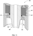
- tool stem 160 may have a stem gear profile 162 on at least a portion of an exterior surface near the top of the tool stem 160.
- Sleeve gear profile 192 may engage stem gear profile 162 when torque sleeve 190 is in a lowered position (shown in Figure 6C ).
- drive stem 180 may turn torque gear profile 195, which engages sleeve gear profile 192, which engages stem gear profile 162, thereby turning tool stem 160.
- tool stem 160 may have a seal package 163 disposed in the central bore 165.
- the seal package 163 may provide a seal of the central bore 165 between the drive stem 180 and the tool stem 160.
- the seal package 163 may be located adjacent to a shoulder 164 or in a recess (not shown) of the interior of tool stem 160.
- the seal package may include high pressure-high temperature (HPHT) dynamic seals.
- HPHT high pressure-high temperature
- the seal package may seal the central bore 165 up to pressures of about 15k psi.
- tool stem 160 may have a threaded coupling on at least a portion of an interior surface near the top of the tool stem 160.
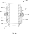
- Drive unit 110 may be coupled to tool adapter 150 in order to transfer bi-directional torque, load, power, data, and/or signals between the top drive and the tool. Coupling of drive unit 110 to tool adapter 150 may proceed as a multi-step process. In an illustrative example not forming any part of the protected scope, as illustrated in Figures 6A-6B , the coupling begins with axial load coupling between drive stem 180 and tool stem 160. Drive stem 180 may be aligned with tool stem 160 so that a lower portion of drive stem 180 may be stabbed into tool stem 160. For example, drive stem 180 may be lowered relative to tool stem 160, and/or tool stem 160 may be raised relative to drive stem 180.
- Threaded coupling 166 may be a heavy-load capacity thread (e.g., stub acme thread).
- An exterior surface of seal sleeve 182 may contact and/or engage with seal package 163.
- Motors 140 may provide torque to make up or break out the axial load connection between tool stem 160 and drive stem 180.
- motors 140 may turn shaft 135, which turns drive gears 130, thereby turning drive gear profile 185 and drive stem 180.
- Threaded coupling 186 on drive stem 180 may engage and mate with threaded coupling 166 on tool stem 160.
- Torque of drive stem 180 may cause threading (or unthreading, depending on direction) between tool stem 160 and drive stem 180.
- the drive stem 180 may have RH male threading, while the tool stem 160 may have RH female threading.
- central bore 165 may provide fluid communication between the top drive and the tool.
- torque in the direction of the threaded couplings 186/166 may also be transferred between the top drive and the tool.
- torque may be transferred from the motors 140 through shaft 135 to the drive gears 130, through drive gear profiles 185 to the drive stem 180, through the threaded couplings 186/166, to the tool stem 160, and to the tool string 2.
- Coupling of drive unit 110 to tool adapter 150 may proceed with bi-directional torque coupling between torque sleeve 190 and tool stem 160, as illustrated in Figures 6B-6C .
- the drive stem 180 may extend through an interior of torque sleeve 190.
- Torque sleeve 190 may move vertically relative to drive stem 180.
- actuators 191 e.g ., hydraulic or pneumatic cylinders, or electric actuators
- drive stem 180 may move torque sleeve 190 between a raised position and a lowered position.
- torque sleeve 190 While tool stem 160 is load coupling with drive stem 180, as shown in Figures 6A-6B , torque sleeve 190 may be in the raised position (relative to drive stem 180).
- Torque sleeve 190 may then move to the lowered position (relative to drive stem 180; Figure 6C ) to engage tool stem 160, thereby transferring torque.
- sleeve gear profile 192 on an interior surface of torque sleeve 190 may engage torque gear profile 195 of drive stem 180 when torque sleeve 190 is in the lowered position (shown in Figure 6C ).
- Drive stem 180 may turn torque gear profile 195 to engage sleeve gear profile 192, thereby turning torque sleeve 190, and sleeve gear profile 192 may also engage stem gear profile 162, thereby turning tool stem 160.
- bi-directional torque may be transferred between the top drive and the tool.
- torque gear profile 195 of drive stem 180 may engage sleeve gear profile 192 of torque sleeve 190, which, when in the lowered position, also engages stem gear profile 162, thereby providing torque to tool stem 160 during drilling operations.
- Bi-directional torque may be thereby transferred from the motors 140 of the drive unit 110 to the tool stem 160, and thus to the tool string 2.
- coupling drive unit 110 to tool adapter 150 may be facilitated with various sensors, actuators, couplers, and/or adapters.
- couplings 170 may include one or more hydraulic, pneumatic, electrical, or optical couplings, providing fluid, electrical, optical, signal, data, and/or power communication between the drive unit 110 and the tool adapter 150.
- Couplings 170 may include tool stem connectors 171 ( Figure 5B ) and mating torque sleeve connectors 172 ( Figure 4B ).
- connectors 171/172 may communicate signals (e.g., hydraulic, pressure, fluid, data, optical, electrical, etc.) from the drive unit 110 to the tool adapter 150.
- connectors 172 may be incorporated on drive stem 180.
- couplings 170 may include a swivel 174 (e.g., a hydraulic swivel or a pneumatic swivel) along drive stem 180.
- Swivel 174 may be disposed co-axially with drive stem 180. Swivel 174 may encircle drive stem 180.
- swivel 174 may be fixed relative to housing 120 while allowing rotation between swivel 174 and drive stem 180.
- swivel 174 may be fixed relative to drive stem 180 while allowing rotation between swivel 174 and housing 120.
- swivel 174 may be free to rotate both relative to drive stem 180 and housing 120.
- coupling drive unit 110 to tool adapter 150 may be facilitated with various sensors.
- the torque sleeve 190 may have sensors 173 ( Figure 4B ) located near its lower edge to ease the alignment process between the couplings 170 located on the drive unit 110 and mating couplings 170 located on the tool adapter 150.
- top drive system 200 is configured and functions similarly to top drive system 100.
- top drive system 200 includes a drive unit 210 and a tool adapter 250.
- the drive unit 210 generally includes a housing 220, becket 225, drive gears 230, motors 240, first portions of one or more couplings 270, and a drive stem 280.
- drive unit 210 includes a spindle unit 290.
- drive unit 210 includes an annular motor 291 (e.g. , hydraulic or electric motor) operationally coupled to components of the spindle unit 290.
- the drive stem 280 may extend through an interior of spindle unit 290. In an illustrative example not forming any part of the protected scope, at least a portion of the annular motor 291 may be fixed relative to the drive stem 280.
- the tool adapter 250 generally includes a tool stem 260 and second portions of the couplings 270.
- the tool stem 260 connects the top drive system 200 to the tool string 2.
- the tool stem 260 and drive stem 280 may share a central bore 265.
- top drive system 200 may transfer bi-directional torque, load, power, data, and/or signals between the top drive and the tool.
- spindle unit 290 generally includes annular motor 291, a spindle 293, and a counter nut 294.
- the drive stem 280 may extend through interiors of annular motor 291, spindle 293, and/or counter nut 294.
- Annular motor 291 is configured to rotate spindle 293 relative to drive stem 280.
- a portion of annular motor 291 is fixed to drive stem 280.
- a portion of annular motor 291 is rotationally coupled to spindle 293.
- annular motor 291 is a 1 MB frameless, maintenance-free asynchronous motor with high power density, available from Bosch Rexroth AG of Lohr, Germany.
- annular motor 291 includes a fixed portion 291-f that is fixed to drive stem 280, and a rotatable portion 291-r that is rotatable relative to drive stem 280.
- rotatable portion 291-r is rotationally coupled to spindle 293.
- rotatable portion 291-r is coupled to a flange 292, which is coupled to spindle 293.
- flange 292 and spindle 293 are permanently fixed together and/or formed as a unified component.
- Annular motor 291 may thereby drive rotation in spindle 293 by rotating rotatable portion 291-r relative to fixed portion 291-f.
- annular motor 291 includes gearing, wheels, tracks, etc., capable of conveying rotational motion (relative to drive stem 280) to spindle 293.
- Counter nut 294 may move vertically relative to drive stem 280 and/or spindle 293
- Annular motor 291 may provide torque, thereby rotating spindle 293 relative to drive stem 280.
- Spindle 293 may have internal threading, and counter nut 294 may have external threading, for example threading 294-t ( Figure 8B ). Spindle 293 may thereby mate with and/or engage counter nut 294.
- Drive stem 280 may have an external guide profile proximate the spindle unit 290, and counter nut 294 may have an internal guide profile, for example guide profile 294-g ( Figure 8B ). Counter nut 294 may thereby mate with and/or engage drive stem 280. Engagement of the guide profiles may prevent rotation between counter nut 294 and drive stem 280.
- a portion of the exterior of drive stem 280 may include a threaded coupling 286.
- coupling of drive unit 210 to tool adapter 250 may proceed as a multi-step process.
- the coupling begins with axial load coupling between drive stem 280 and tool stem 260.
- Drive stem 280 may be aligned with tool stem 260 so that a lower portion of drive stem 280 may be stabbed into tool stem 260.
- Drive stem 280 may rotate relative to tool stem 260 so that threaded coupling 286 on drive stem 280 engages and mates with threaded coupling 266 on tool stem 260 ( Figure 9B ).
- Spindle unit 290 may remain fixed relative to drive stem 280 during axial load coupling.
- annular motor 291 may reduce or prevent rotation of spindle unit 290 relative to drive stem 280 during axial load coupling.
- Counter nut 294 may be in a raised position relative to drive stem 280 during axial load coupling.
- Motors 240 may provide torque to make up or break out the axial load connection between tool stem 260 and drive stem 280.
- Torque of drive stem 280 may cause threading (or unthreading, depending on direction) between tool stem 260 and drive stem 280.
- Threaded coupling 286 of drive stem 280 may be RH male threading, while threaded coupling 266 of tool stem 260 may be RH female threading.
- axial load may be transferred between the top drive and the tool.
- central bore 265 may provide fluid communication between the top drive and the tool.
- torque in the direction of the threaded couplings 286/266 may also be transferred between the top drive and the tool.
- torque may be transferred from the motors 240 through shaft 235 to the drive gears 230, through drive gear profiles 285 to the drive stem 280, through the threaded couplings 286/266, to the tool stem 260, and to the tool string 2.
- Coupling of drive unit 210 to tool adapter 250 may proceed with bi-directional torque coupling between drive stem 280 and tool stem 260, as illustrated in Figures 9B-9C .
- Annular motor 291 may rotate spindle 293 relative to drive stem 280.
- Annular motor 291 may thereby rotate spindle 293 relative to counter nut 294.
- Rotation of spindle 293 relative to counter nut 294 may cause vertical motion of counter nut 294 due to the threaded coupling between spindle 293 and counter nut 294 ( e.g ., threading 294-t on counter nut 294) and the guided coupling between drive stem 280 and counter nut 294 ( e.g ., guide profile 294-g on counter nut 294).
- rotation of drive stem 280 in a direction (“loosening direction”) that would break up or loosen the connection between threaded coupling 266 and threaded coupling 286 may thereby also force counter nut 294 downwards relative to drive stem 280.
- rotation of drive stem 280 in the loosing direction may serve to transfer torque to tool stem 260.
- rotation of drive stem 280 in the opposite direction (“tightening direction”) may serve to transfer torque to tool stem 260 through the connection of threaded coupling 266 with threaded coupling 286.
- De-coupling drive unit 210 from tool adapter 250 includes reverse rotation of spindle 293.
- Annular motor 291 may reverse the rotation of spindle 293, and thereby raising counter nut 294 relative to drive stem 280. Movement of counter nut 294 away from contact with tool stem 260 ( Figure 9B ) allows rotation of drive stem 280 in the loosening direction to break up or loosen the connection between threaded coupling 266 and threaded coupling 286.
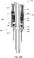
- top drive system 300 illustrates an alternative top drive system 300 according to embodiments of the invention described herein. Except as noted, top drive system 300 is configured and functions similarly to top drive system 100 and top drive system 200.
- top drive system 300 includes a drive unit 310 and a tool adapter 350.
- the drive unit 310 generally includes a housing 320, becket 325, drive gears 330, motors 340, first portions of one or more couplings 370, and a drive stem 380.
- drive unit 310 includes a (torque) transmission unit 390.
- drive unit 310 includes a swivel 321 and a selection ring 395.
- the drive stem 380 may extend through an interior of torque transmission unit 390 and an interior of selection ring 395. At least a portion of swivel 321 may be fixed relative to the housing 320, and swivel 321 may encircle drive stem 380.
- swivel 321 may include a stationary portion 321-s that is fixed relative to housing 320 and a rotatable portion 321-r that may rotate relative to housing 320.
- the rotatable portion 321-r may be rotationally fixed to selection ring 395.
- the stationary portion 321-s may encircle the rotatable portion 321-r.
- Drive stem 380 may have friction surfaces 387 that parallel and may engage with friction surfaces 397 of transmission unit 390.
- the tool adapter 350 generally includes a tool stem 360 and second portions of the couplings 370.
- the tool stem 360 connects the top drive system 300 to the tool string 2.
- the tool stem 360 and drive stem 380 may share a central bore 365.
- top drive system 300 may transfer bi-directional torque, load, power, data, and/or signals between the top drive and the tool.
- transmission unit 390 generally includes couplings 370, one or more shoulders 394 proximate a bottom of the transmission unit 390, one or more coupling holes 391 proximate a top of the transmission unit 390, and one or more friction surfaces 397.
- the drive stem 380 may extend through the interior of transmission unit 390. Friction surfaces 387 of drive stem 380 may parallel and may engage with friction surfaces 397 of transmission unit 390.
- drive stem 380 includes eight disks projecting radially outward, each disk having two friction surfaces 387 ( i.e., a top surface and a bottom surface).
- transmission unit 390 has nine annular disks encircling drive stem 380 and interleaved with the eight disks of the drive stem 380, each of the annular disks having one or two friction surfaces 397 ( i.e ., a top surface and a bottom surface).
- friction surfaces 387/397 may be selectively engaged.
- a transmission selector 393 ( Figure 12 ) from selection ring 395 may be actuated ( e.g ., hydraulically) to apply a compressive (normal) force to the interleaved friction surfaces 387/397.
- Engagement of friction surfaces 387 with friction surfaces 397 may rotationally couple drive stem 380 with transmission unit 390.
- a portion of the exterior of drive stem 380 may include a threaded coupling 386.
- Shoulders 394 may convey torque between transmission unit 390 and tool stem 360.
- shoulders 394 may be disposed on an interior surface of transmission unit 390.
- Complementary shoulders 364 may be disposed on an exterior surface of tool stem 360 ( Figure 13A ).
- the shoulders 394/364 may have guiding chamfers. It should be appreciated that other torque coupling types and/or configurations may be considered to accommodate manufacturing and operational conditions.
- selection ring 395 includes one or more coupling pins 396 engagable with coupling holes 391 of transmission unit 390, one or more swivel selector 392 and one or more transmission selector 393.
- the coupling pins 396 may be actuated ( e.g ., hydraulically) to engage with coupling holes 391, thereby rotationally fixing selection ring 395 with transmission unit 390.
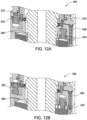
- Each selector 392/393 may be movable to an "on” position or an "off” position.
- the drive stem 380 may extend through an interior of selection ring 395. When swivel selector 392 is "on”, selection ring 395 may move synchronously with stationary portion 321-s of swivel 321.
- swivel selector 392 may include a pin that moves between an upper position ( Figure 12A ) and a lower position ( Figure 12B ). When the pin of swivel selector 392 is in the upper position, the swivel selector 392 is "on", and selection ring 395 may move synchronously with stationary portion 321-s of swivel 321.
- transmission selector 393 may include a pin that moves between an upper position ( Figure 12A ) and a lower position ( Figure 12B ). Transmission selector 393 may engage transmission unit friction surfaces 397 with drive stem friction surfaces 387. For example, transmission selector 393 may compress transmission unit friction surfaces 397 against drive stem friction surfaces 387.
- swivel selector 392 and/or transmission selector 393 may include or be actuated by a hydraulic cylinder. As would be understood by one of ordinary skill in the art with the benefit of this disclosure, other configurations of swivel selectors 392 and transmission selectors 393 may be considered to accommodate manufacturing and operational conditions.
- transmission unit 390 may simply be fixed to selection ring 395. It should be appreciated that coupling holes 391 and coupling pins 396 may be beneficial for maintenance purposes.
- coupling of drive unit 310 to tool adapter 350 may proceed as a multi-step process.
- the coupling begins with axial load coupling between drive stem 380 and tool stem 360.
- Drive stem 380 may be aligned with tool stem 360 so that a lower portion of drive stem 380 may be stabbed into tool stem 360.
- Transmission unit 390 may also be aligned with tool stem 360 so that shoulders 394 align with corresponding shoulders 364 on tool stem 360.
- shoulders 394 may include concave features on an interior surface of transmission unit 390, while corresponding shoulders 364 include convex features on an exterior surface of tool stem 360.
- transmission selector 393 may be initially moved to "on,” swivel selector 392 may be initially moved to “off,” and coupling pins 396 may engage coupling holes 391, so that rotation of drive stem 380 may be used to align transmission unit 390 with tool stem 360. Once transmission unit 390 is aligned with tool stem 360, transmission selector 393 may then be moved to "off” to allow free rotation of drive stem 380 relative to transmission unit 390.
- Drive stem 380 may rotate relative to tool stem 360 so that threaded coupling 386 on drive stem 380 engage and mate with threaded coupling 366 on tool stem 360 ( Figures 13B-13C ).
- transmission unit 390 may remain fixed relative to housing 320 during axial load coupling.
- swivel selector 392 may be set to “on” and coupling pins 396 may engage coupling holes 391 during axial load coupling.
- Selection ring 395 may thereby synchronize with stationary portion 321-s of swivel 321, which may be fixed relative to the housing 320.
- transmission selector 393 may be "off” during axial load coupling, so transmission unit friction surfaces 397 may not be engaged with drive stem friction surfaces 387. Consequently, transmission unit 390 may not rotate with drive stem 380 during axial load coupling.
- Motors 340 may provide torque to make up or break out the axial load connection between tool stem 360 and drive stem 380.
- Torque of drive stem 380 may cause threading (or unthreading, depending on direction) between tool stem 360 and drive stem 380.
- Threaded coupling 386 of drive stem 380 may be RH male threading, while threaded coupling 366 of tool stem 260 may be RH female threading.
- axial load may be transferred between the top drive and the tool.
- central bore 365 may provide fluid communication between the top drive and the tool.
- couplings 370 may communicate pneumatic, hydraulic, electrical, optical, or other power and/or signals between drive unit 310 and tool adapter 350.
- swivel 321 may provide torque to make up or break out the threaded coupling 366.
- a rotational actuator may be coupled between housing 320 and stationary portion 321-s of swivel 321.
- Stationary portion 321-s may not be rotationally fixed to housing 320, but may have some rotational freedom of movement (e.g., less than about 60 degrees).
- swivel 321 may be used as a wrenching tong for make up if the motors 340 cannot apply sufficient torque.
- Coupling of drive unit 310 to tool adapter 350 may proceed with bi-directional torque coupling between drive stem 380 and tool stem 360, as illustrated in Figures 13C-13E .
- Shoulders 394 on transmission unit 390 may align and mate with corresponding shoulders 364 on tool stem 360. It should be appreciated that, immediately following axial load coupling, residual torque may exist in tool string 2.
- Drive stem 380 may counter the residual torque while making-up threaded coupling 366 ( Figures 13B-13C ).
- drive stem 380 may be rotationally coupled to transmission unit 390 following axial load coupling to further counter the residual torque.
- transmission selector 393 may be moved to "on,” while swivel selector 392 may remain “on,” and coupling pins 396 may continue engage coupling holes 391 ( Figure 13D ).
- Selection ring 395 may then safely switch from having swivel selector 392 "on” ( Figures 13A-13D ) to having swivel selector 392 “off” ( Figure 13E ).
- residual torque may be transferred from tool string 2 through tool stem 360 to shoulders 364, to shoulders 394, and to transmission unit 390.
- selection ring 395 and transmission unit 390 may both rotationally synchronize with drive stem 380.
- Drive stem 380 may thereby counter any residual torque from tool string 2.
- bi-directional torque may be transferred between the top drive and the tool.
- torque may be transferred from the motors 340 through shaft 335 (not shown) to the drive gears 330, to the drive stem 380, through the friction surfaces 387/397 to the transmission unit 390, through the mated shoulders 394/364 to tool stem 360, and to the tool string 2.
- Bi-directional torque may be thereby transferred from the motors 340 of the drive unit 310 to the tool stem 360, and thus to the tool string 2.
- coupling drive unit 310 to tool adapter 350 may be facilitated with various sensors, cameras, actuators, couplers, and/or adapters.
- signals and/or power may be transferred between the rotatable portion 321-r of swivel 321 and the selection ring 395 by connections 322 ( Figure 12 ).
- swivel selector 392 and transmission selector 393 are hydraulic cylinders, and connections 322 may provide hydraulic control signals to swivel selector 392 and transmission selector 393.
- signals and/or power may be transferred between transmission unit 390 and tool stem 360 by couplings 370.
- coupling drive unit 310 to tool adapter 350 may be facilitated with sensors to detect misalignments between components.
- swivel selector 392 when swivel selector 392 is "on" ( Figure 13A ), swivel selector 392 extends from selection ring 395 into a recess of swivel 321. Rotational misalignment of selection ring 395 and swivel 321 would not allow swivel selector 392 to extend from selection ring 395 into the recess of swivel 321.
- a sensor e.g ., an optical sensor
- transmission unit 390 may be first oriented relative to tool stem 360 so that shoulders 394 align with shoulders 364.
- a sensor e.g., an optical sensor
- the sensor may be configured to detect a marker (e.g. , a reflector) disposed at the top of tool stem 360.
- Transmission unit 390 may be rotated relative to tool stem 360 until the sensor detects alignment with the marker.
- multiple markers may be utilized.
- transmission unit 390 may be appropriately oriented in two or more orientations relative to tool stem 360. The sensor need only detect alignment with the first marker to identify appropriate orientation of transmission unit 390 relative to tool stem 360.
- connections 322 may include a retractable adapter that allows for slight misalignments.
- adapters may allow for connection 322 to be made between the rotatable portion 321-r of swivel 321 and selection ring 395 even with slight rotational and/or positional misalignment. Once connection 322 has been made, the adapter may maintain connection 322 f while selection ring 395 moves synchronously with swivel 321, even if a slight misalignment develops.
- coupling drive unit 310 to tool adapter 350 may be facilitated with remote control actuators.
- swivel selector 392 and/or transmission selector 393 may be remotely controlled.
- the actuators may be, for example, worm drives, hydraulic cylinders, compensation cylinders, etc.
- the actuators may be hydraulically, pneumatically, electrically, and/or manually controlled.
- multiple control mechanism may be utilized to provide redundancy.
- One or more sensors may be used to monitor relative positions of the components of the top drive system.
- the sensors may be position sensors, rotation sensors, pressure sensors, optical sensors, magnetic sensors, etc.
- stop surfaces may be used in conjunction with or in lieu of sensors to identify when components are appropriately positioned and/or oriented.
- optical guides may be utilized to identify or confirm when components are appropriately positioned and/or oriented.
- guide elements e.g ., pins and holes, chamfers, etc.
- Bearings and seals may be disposed between components to provide support, cushioning, rotational freedom, and/or fluid management.
- a drive unit of a top drive system includes a drive stem having a torque gear profile and a load coupling, wherein the load coupling is a threaded coupling; and a torque sleeve movable between a first position and a second position, and having a sleeve gear profile that engages the torque gear profile when the torque sleeve is in the second position.
- the first position of the torque sleeve is a raised position
- the second position of the torque sleeve is a lowered position
- the drive stem comprises a drive gear profile engagable with the motor.
- the drive stem extends through an interior of the torque sleeve.
- the drive unit also includes a swivel co-axial with the drive stem.
- the swivel is a hydraulic swivel.
- the drive unit also includes an actuator configured to move the torque sleeve between the first position and the second position.
- the actuator is a hydraulic cylinder.
- the top drive system also includes a tool adapter having a complementary load coupling to the load coupling of the drive stem, and a stem gear profile that is complementary to the sleeve gear profile.
- the top drive system also includes at least one coupling between the drive unit and the tool adapter selected from a group consisting of: threaded couplings, hydraulic couplings, pneumatic couplings, electronic couplings, fiber optic couplings, power couplings, data couplings, signal couplings, bi-directional torque couplings, axial load couplings, power couplings, data couplings, and signal couplings.
- a method of coupling a drive unit to a tool adapter includes positioning the tool adapter below the drive unit; rotating a drive stem of the drive unit to make up a threaded coupling with a tool stem of the tool adapter; and moving a torque sleeve of the drive unit to engage both a torque gear profile of the drive stem and a stem gear profile of the tool stem.
- moving the torque sleeve comprises moving the torque sleeve from a raised position to a lowered position.
- the method also includes forming a coupling between the drive unit and the tool adapter, wherein the coupling is selected from a group consisting of: threaded couplings, hydraulic couplings, pneumatic couplings, electronic couplings, fiber optic couplings, power couplings, data couplings, signal couplings, bi-directional torque couplings, axial load couplings, power couplings, data couplings, and signal couplings.
- the coupling is selected from a group consisting of: threaded couplings, hydraulic couplings, pneumatic couplings, electronic couplings, fiber optic couplings, power couplings, data couplings, signal couplings, bi-directional torque couplings, axial load couplings, power couplings, data couplings, and signal couplings.
- the method also includes transferring torque from the drive stem through the torque sleeve to the tool stem.
- the method also includes transferring axial load with the threaded coupling between the drive stem and the tool stem.
- a drive unit of a top drive system includes a drive stem having a load coupling that is a threaded coupling; a spindle unit comprising: an interior through which the drive stem extends; a counter nut having a first guide profile mated with a second guide profile on the drive stem; and a spindle having threading mated with threading on the counter nut; and an annular motor operationally coupled to the spindle unit.
- the annular motor comprises a fixed portion that is fixed to the drive stem and a rotatable portion that is rotatable relative to the drive stem.
- the rotatable portion is rotationally coupled to the spindle.
- the first guide profile is on an interior surface of the counter nut and the threading is on an exterior surface of the counter nut.
- the drive unit also includes a motor, wherein the drive stem comprises a drive gear profile engagable with the motor.
- At least a portion of the annular motor is fixed relative to the drive stem.
- the top drive system also includes a tool adapter having a complementary load coupling to the load coupling of the drive stem, and a shoulder proximate a top of the tool adapter.
- the top drive system also includes at least one coupling between the drive unit and the tool adapter selected from a group consisting of: threaded couplings, hydraulic couplings, pneumatic couplings, electronic couplings, fiber optic couplings, power couplings, data couplings, signal couplings, bi-directional torque couplings, axial load couplings, power couplings, data couplings, and signal couplings.
- a method of coupling a drive unit to a tool adapter includes positioning the tool adapter below the drive unit; rotating a drive stem of the drive unit to make up a threaded coupling with a tool stem of the tool adapter; and rotating a spindle unit relative to the drive stem to contact a counter nut of the spindle unit with the tool stem.
- the spindle unit remains fixed relative to the drive stem while rotating the drive stem to make up the threaded coupling.
- rotating the spindle unit relative to the drive stem moves the counter nut vertically relative to the drive stem.
- the method also includes forming a coupling between the drive unit and the tool adapter, wherein the coupling is selected from a group consisting of: threaded couplings, hydraulic couplings, pneumatic couplings, electronic couplings, fiber optic couplings, power couplings, data couplings, signal couplings, bi-directional torque couplings, axial load couplings, power couplings, data couplings, and signal couplings.
- the coupling is selected from a group consisting of: threaded couplings, hydraulic couplings, pneumatic couplings, electronic couplings, fiber optic couplings, power couplings, data couplings, signal couplings, bi-directional torque couplings, axial load couplings, power couplings, data couplings, and signal couplings.
- the method also includes transferring bi-directional torque with the threaded coupling between the drive stem and the tool stem.
- the method also includes transferring axial load with the threaded coupling between the drive stem and the tool stem.
- a drive unit of a top drive system includes a drive stem having first friction surfaces and a load coupling, wherein the load coupling is a threaded coupling; a transmission unit having: second friction surfaces parallel to the first friction surfaces; and shoulders proximate a bottom of the transmission unit; and a transmission selector movable to an "on" position or an “off” position, wherein the drive stem moves synchronously with the transmission unit when the transmission selector is in the "on" position.
- the drive unit also includes a swivel selector movable to an "on" position or an “off” position, wherein the transmission unit moves synchronously with a swivel of the drive unit when the swivel selector is in the "on" position.
- the swivel comprises a stationary portion and a rotatable portion, and the swivel selector couples to the stationary portion.
- the drive unit also includes a selection ring that includes the transmission selector.
- the selection ring comprises coupling pins
- the transmission unit comprises coupling holes engagable with the coupling pins
- the first friction surfaces are top and bottom surfaces of disks projecting radially outward on the drive stem
- the second friction surfaces are top and bottom surfaces of annular disks encircling the drive stem.
- the top drive system also includes a tool adapter having a complementary load coupling to the load coupling of the drive stem, and shoulders complementary to those of the transmission unit.
- the top drive system also includes at least one coupling between the drive unit and the tool adapter selected from a group consisting of: threaded couplings, hydraulic couplings, pneumatic couplings, electronic couplings, fiber optic couplings, power couplings, data couplings, signal couplings, bi-directional torque couplings, axial load couplings, power couplings, data couplings, and signal couplings.
- at least one coupling between the drive unit and the tool adapter selected from a group consisting of: threaded couplings, hydraulic couplings, pneumatic couplings, electronic couplings, fiber optic couplings, power couplings, data couplings, signal couplings, bi-directional torque couplings, axial load couplings, power couplings, data couplings, and signal couplings.
- the shoulders of the transmission unit are on an interior surface of the transmission unit, and the shoulders of the tool adapter are on an exterior surface of a tool stem of the tool adapter.
- a method of coupling a drive unit to a tool adapter includes positioning the tool adapter below the drive unit so that shoulders of a transmission unit of the drive unit align with shoulders of a tool stem of the tool adapter; and rotating a drive stem of the drive unit to make up a threaded coupling with the tool stem, wherein: the drive stem and the transmission unit rotate together during the positioning of the tool adapter; and the drive stem and the transmission unit do not rotate together during the making up of the threaded coupling.
- the method also includes, before making up the threaded coupling, moving a swivel selector to an "on" position to rotationally couple the transmission unit with a housing of the drive unit.
- the method also includes rotating a portion of a swivel relative to the housing to wrench the threaded coupling.
- the method also includes, after making up the threaded coupling, moving a transmission selector to an "on" position.
- the method also includes, after moving the transmission selector to the "on” position, moving a swivel selector to an "off" position.
- the method also includes forming a coupling between the drive unit and the tool adapter, wherein the coupling is selected from a group consisting of: threaded couplings, hydraulic couplings, pneumatic couplings, electronic couplings, fiber optic couplings, power couplings, data couplings, signal couplings, bi-directional torque couplings, axial load couplings, power couplings, data couplings, and signal couplings.
- the coupling is selected from a group consisting of: threaded couplings, hydraulic couplings, pneumatic couplings, electronic couplings, fiber optic couplings, power couplings, data couplings, signal couplings, bi-directional torque couplings, axial load couplings, power couplings, data couplings, and signal couplings.
- the method also includes transferring torque from the drive stem to the transmission unit through frictional surfaces.
- the method also includes mating the shoulders of the transmission unit with the shoulders of the tool stem to transfer torque from the drive stem to the tool stem.
- the method also includes transferring axial load with the threaded coupling between the drive stem and the tool stem.
Landscapes
- Engineering & Computer Science (AREA)
- Life Sciences & Earth Sciences (AREA)
- Geology (AREA)
- Mining & Mineral Resources (AREA)
- General Engineering & Computer Science (AREA)
- Mechanical Engineering (AREA)
- Physics & Mathematics (AREA)
- Environmental & Geological Engineering (AREA)
- Fluid Mechanics (AREA)
- General Life Sciences & Earth Sciences (AREA)
- Geochemistry & Mineralogy (AREA)
- Earth Drilling (AREA)
Claims (15)
- Système d'entraînement par le haut (300) pour coupler un entraînement par le haut à un outil, le système comprenant :une tige d'entraînement (380) ayant des premières surfaces de friction (387) et un connecteur de charge, dans lequel le connecteur de charge est un connecteur fileté (386) configuré pour s'engager avec un connecteur fileté (366) sur une tige d'outil (360) d'un adaptateur d'outil (350);un pivot (321) disposé autour de la tige d'entraînement ;une unité de transmission (390) ayant :des deuxièmes surfaces de frottement (397) parallèles aux premières surfaces de frottement ; etdes épaulements (394) à proximité d'une partie inférieure de l'unité de transmission, dans lequel lesdits épaulements sont configurés pour transmettre un couple entre l'unité de transmission et la tige d'outil (360) ;un sélecteur de transmission (393) mobile vers une position "marche" ou une position "arrêt", dans lequel, lorsque le sélecteur de transmission est dans la position "marche", les premières surfaces de friction (387) s'engagent avec les deuxièmes surfaces de friction (397) de telle sorte que la tige d'entraînement se déplace de manière synchrone avec l'unité de transmission ; etun sélecteur pivotant (392) mobile vers une position "marche" ou une position "arrêt", dans lequel, lorsque le sélecteur pivotant est dans la position "marche", l'unité de transmission se déplace de manière synchrone avec le pivot.
- Système d'entraînement par le haut selon la revendication 1, dans lequel le pivot (321) comprend une partie fixe (321-s) et une partie rotative (321-r), et le sélecteur de pivot (392) se couple à la partie fixe.
- Système d'entraînement par le haut selon la revendication 1 ou 2, comprenant en outre un anneau de sélection (395) qui inclut le sélecteur de transmission (393), dans lequel l'anneau de sélection comprend optionnellement des broches de connexion (396), et l'unité de transmission (390) comprend des trous de connexion (391) pouvant s'engager avec les broches de connexion.
- Système d'entraînement par le haut selon l'une quelconque des revendications précédentes, dans lequel les premières surfaces de frottement (387) sont des surfaces supérieure et inférieure de disques faisant saillie radialement vers l'extérieur sur la tige d'entraînement (380), et les deuxièmes surfaces de frottement (397) sont des surfaces supérieure et inférieure de disques annulaires entourant la tige d'entraînement.
- Système d'entraînement par le haut selon l'une quelconque des revendications précédentes, comprenant en outre l'adaptateur d'outil (350) ayant une connexion de charge complémentaire (370) à la connexion de charge de la tige d'entraînement (380), et des épaulements complémentaires à ceux de l'unité de transmission (390).
- Système d'entraînement par le haut selon la revendication 5, comprenant en outre au moins un connecteur entre l'unité de transmission (390) et l'adaptateur d'outil (350) sélectionné dans un groupe constitué de : connecteurs hydrauliques, connecteurs pneumatiques, connecteurs électroniques, connecteurs à fibre optique, connecteurs de puissance, connecteurs de données, connecteurs de couple bidirectionnels, connecteurs de charge axiale et connecteurs de signal.
- Système d'entraînement par le haut selon la revendication 5 ou 6, dans lequel les épaulements de l'unité de transmission (390) sont sur une surface intérieure de l'unité de transmission, et les épaulements de l'adaptateur d'outil (350) sont sur une surface extérieure de la tige d'outil de l'adaptateur d'outil.
- Procédé d'accouplement d'une unité d'entraînement (310) à un adaptateur d'outil (350), le procédé comprenant :le positionnement de l'adaptateur d'outil sous l'unité d'entraînement de sorte que les épaulements d'une unité de transmission (390) de l'unité d'entraînement s'alignent avec les épaulements d'une tige d'outil (360) de l'adaptateur d'outil, dans lequel l'unité d'entraînement inclut en outre :un pivot (321) autour d'une tige d'entraînement (380), des premières surfaces de friction (387) prévues sur la tige d'entraînement (380) et un connecteur de charge entre la tige d'entraînement (380) et la tige d'outil (360) qui est un connecteur fileté (386) sur la tige d'entraînement (380) configuré pour s'engager et s'accoupler avec un connecteur fileté (366) sur la tige d'outil ; etune unité de transmission (390) ayant des secondes surfaces de friction (397) parallèles aux premières surfaces de friction et des épaulements (394) à proximité d'une partie inférieure de l'unité de transmission, dans laquelle lesdits épaulements sont configurés pour transmettre un couple entre l'unité de transmission et la tige d'outil (360) ;le déplacement d'un sélecteur de transmission (393) vers une position "marche", dans lequel, lorsque le sélecteur de transmission est dans la position "marche", les premières surfaces de friction (387) s'engagent avec les deuxièmes surfaces de friction (397) de sorte que la tige d'entraînement se déplace de façon synchrone avec l'unité de transmission ;le déplacement d'un sélecteur pivotant (392) vers une position "marche" pour coupler en rotation l'unité de transmission (390) avec un boîtier de l'unité d'entraînement (310), dans lequel, lorsque le sélecteur pivotant est dans la position "marche", l'unité de transmission se déplace de façon synchrone avec le pivot; etla rotation de la tige d'entraînement (380) de l'unité d'entraînement pour constituer une connexion filetée avec la tige d'outil, dans lequel :la tige d'entraînement et l'unité de transmission tournent ensemble pendant le positionnement de l'adaptateur d'outil ; etla tige d'entraînement et l'unité de transmission ne tournent pas ensemble lors de la constitution de la connexion filetée.
- Procédé selon la revendication 8, comprenant en outre, avant de constituer la connexion filetée, le déplacement du sélecteur pivotant (392) vers une position "marche" pour coupler en rotation l'unité de transmission (390) avec un boîtier de l'unité d'entraînement (310).
- Procédé selon la revendication 9, comprenant en outre la rotation d'une partie du pivot (321) par rapport au boîtier pour visser la connexion filetée.
- Procédé selon la revendication 10, comprenant en outre, après la constitution de la connexion filetée, le déplacement du sélecteur de transmission (393) vers une position "marche", et optionnellement comprenant en outre, après déplacement du sélecteur de transmission vers la position "marche", le déplacement d'un sélecteur pivotant (392) vers une position "arrêt".
- Procédé selon l'une quelconque des revendications 8 à 11, comprenant en outre la formation d'un connecteur entre l'unité d'entraînement (310) et l'adaptateur d'outil (350), dans lequel le connecteur est sélectionné dans un groupe constitué de : connecteurs filetés, connecteurs hydrauliques, connecteurs pneumatiques, connecteurs électroniques, connecteurs de fibre optique, connecteurs de couple bidirectionnels, connecteurs de charge axiale, connecteurs de puissance, connecteurs de données et connecteurs de signal.
- Procédé selon l'une quelconque des revendications 8 à 12, comprenant en outre le transfert du couple de la tige d'entraînement (380) à l'unité de transmission (390) à travers les surfaces de frottement.
- Procédé selon l'une quelconque des revendications 8 à 13, comprenant en outre l'accouplement des épaulements de l'unité de transmission (390) avec les épaulements de la tige d'outil (360) pour transférer le couple de la tige d'entraînement (380) à la tige d'outil.
- Procédé selon la revendication 14, comprenant en outre le transfert de la charge axiale avec la connexion filetée entre la tige d'entraînement (380) et la tige d'outil (360).
Applications Claiming Priority (2)
| Application Number | Priority Date | Filing Date | Title |
|---|---|---|---|
| US15/457,572 US10247246B2 (en) | 2017-03-13 | 2017-03-13 | Tool coupler with threaded connection for top drive |
| EP18161224.3A EP3404196B1 (fr) | 2017-03-13 | 2018-03-12 | Coupleur d'outil à connexion filetée pour un entraînement supérieur |
Related Parent Applications (1)
| Application Number | Title | Priority Date | Filing Date |
|---|---|---|---|
| EP18161224.3A Division EP3404196B1 (fr) | 2017-03-13 | 2018-03-12 | Coupleur d'outil à connexion filetée pour un entraînement supérieur |
Publications (2)
| Publication Number | Publication Date |
|---|---|
| EP3779115A1 EP3779115A1 (fr) | 2021-02-17 |
| EP3779115B1 true EP3779115B1 (fr) | 2023-07-05 |
Family
ID=63444509
Family Applications (2)
| Application Number | Title | Priority Date | Filing Date |
|---|---|---|---|
| EP20197429.2A Active EP3779115B1 (fr) | 2017-03-13 | 2018-03-12 | Coupleur d'outil à connexion filetée pour un entraînement supérieur |
| EP18161224.3A Active EP3404196B1 (fr) | 2017-03-13 | 2018-03-12 | Coupleur d'outil à connexion filetée pour un entraînement supérieur |
Family Applications After (1)
| Application Number | Title | Priority Date | Filing Date |
|---|---|---|---|
| EP18161224.3A Active EP3404196B1 (fr) | 2017-03-13 | 2018-03-12 | Coupleur d'outil à connexion filetée pour un entraînement supérieur |
Country Status (3)
| Country | Link |
|---|---|
| US (2) | US10247246B2 (fr) |
| EP (2) | EP3779115B1 (fr) |
| CA (1) | CA2997740C (fr) |
Families Citing this family (2)
| Publication number | Priority date | Publication date | Assignee | Title |
|---|---|---|---|---|
| KR102149976B1 (ko) * | 2019-07-12 | 2020-08-31 | 산동금속공업(주) | 스레드의 체결 구조를 개선한 방향성 추진체 |
| CN120007106B (zh) * | 2025-03-20 | 2025-10-28 | 中海石油(中国)有限公司 | 一种用于智能钻杆系统的钻杆接头结构及安装方法 |
Citations (1)
| Publication number | Priority date | Publication date | Assignee | Title |
|---|---|---|---|---|
| FR2531479A1 (fr) * | 1982-08-03 | 1984-02-10 | Varco Int | Forage de puits avec unite de commande au sommet |
Family Cites Families (282)
| Publication number | Priority date | Publication date | Assignee | Title |
|---|---|---|---|---|
| US1367156A (en) | 1920-03-16 | 1921-02-01 | Budd D Mcalvay | Interlocking casing-reducing nipple |
| US1610977A (en) | 1924-12-03 | 1926-12-14 | Henry T Scott | Coupling |
| US1822444A (en) | 1930-01-20 | 1931-09-08 | John W Macclatchie | Cementing head |
| US2370354A (en) | 1943-06-07 | 1945-02-27 | George L Hurst | Quick detachable coupling |
| US3147992A (en) | 1961-04-27 | 1964-09-08 | Shell Oil Co | Wellhead connector |
| US3144085A (en) * | 1962-04-12 | 1964-08-11 | Malvern M Hasha | Power spinner unit for well swivels |
| US3354951A (en) | 1964-02-24 | 1967-11-28 | Offshore Co | Marine drilling apparatus |
| US3385370A (en) | 1966-06-29 | 1968-05-28 | Halliburton Co | Self-fill and flow control safety valve |
| US3747675A (en) | 1968-11-25 | 1973-07-24 | C Brown | Rotary drive connection for casing drilling string |
| US3662842A (en) | 1970-04-14 | 1972-05-16 | Automatic Drilling Mach | Automatic coupling system |
| US3698426A (en) | 1970-07-29 | 1972-10-17 | Smith International | Mud saver valve and method |
| US3766991A (en) | 1971-04-02 | 1973-10-23 | Brown Oil Tools | Electric power swivel and system for use in rotary well drilling |
| US3888318A (en) | 1971-09-16 | 1975-06-10 | Cicero C Brown | Well drilling apparatus |
| US3774697A (en) | 1971-12-09 | 1973-11-27 | C Brown | Rotary drive assembly for handling tubular members |
| US3776320A (en) | 1971-12-23 | 1973-12-04 | C Brown | Rotating drive assembly |
| US3842619A (en) | 1972-08-16 | 1974-10-22 | A Bychurch | Reversible kelly system for rotary drilling |
| US3913687A (en) | 1974-03-04 | 1975-10-21 | Ingersoll Rand Co | Pipe handling system |
| US3915244A (en) | 1974-06-06 | 1975-10-28 | Cicero C Brown | Break out elevators for rotary drive assemblies |
| GB1487948A (en) | 1974-12-16 | 1977-10-05 | Hunting Oilfield Services Ltd | Pipe connectors |
| US3899024A (en) | 1975-01-10 | 1975-08-12 | Production Data Inc | Auxiliary oil well tubing shut-off assembly |
| US3964552A (en) | 1975-01-23 | 1976-06-22 | Brown Oil Tools, Inc. | Drive connector with load compensator |
| US4022284A (en) | 1975-03-17 | 1977-05-10 | Dresser Industries, Inc. | Automatic alignment system for earth boring rig |
| US4051587A (en) | 1976-08-02 | 1977-10-04 | Varco International, Inc. | Pile handling apparatus and methods |
| US4100968A (en) | 1976-08-30 | 1978-07-18 | Charles George Delano | Technique for running casing |
| CA1069494A (fr) | 1977-07-21 | 1980-01-08 | Bralorne Resources Limited | Raccord coulissant a coussin amortisseur |
| US4199847A (en) | 1979-01-29 | 1980-04-29 | Armco Inc. | Well riser support having elastomeric bearings |
| US4402239A (en) | 1979-04-30 | 1983-09-06 | Eckel Manufacturing Company, Inc. | Back-up power tongs and method |
| US4235469A (en) | 1979-05-11 | 1980-11-25 | Den-Con Tool Company | Pipe handling apparatus |
| US4374595A (en) | 1980-06-16 | 1983-02-22 | Hughes Tool Company | Metal to metal sealed joint for tubing string |
| US4377179A (en) | 1980-10-28 | 1983-03-22 | Bernhardt & Frederick Co., Inc. | Pressure balanced ball valve device |
| US4364407A (en) | 1981-02-23 | 1982-12-21 | Hilliard David R | Mud saver valve |
| US4478244A (en) | 1983-01-05 | 1984-10-23 | Garrett William R | Mud saver valve |
| CA1224715A (fr) | 1983-02-18 | 1987-07-28 | Peter R. Gibb | Methode et dispositif de raccordement du materiel d'extraction en mer a une plate-forme flottante |
| US4497224A (en) | 1983-08-11 | 1985-02-05 | Norton Christensen, Inc. | Apparatus for making and breaking screw couplings |
| NO154578C (no) | 1984-01-25 | 1986-10-29 | Maritime Hydraulics As | Broennboreinnretning. |
| JPH0240385Y2 (fr) | 1986-02-14 | 1990-10-29 | ||
| US4693497A (en) | 1986-06-19 | 1987-09-15 | Cameron Iron Works, Inc. | Collet connector |
| US4779688A (en) | 1986-07-23 | 1988-10-25 | Baugh Benton F | Mud saver valve |
| US4821814A (en) | 1987-04-02 | 1989-04-18 | 501 W-N Apache Corporation | Top head drive assembly for earth drilling machine and components thereof |
| US4815546A (en) | 1987-04-02 | 1989-03-28 | W-N Apache Corporation | Top head drive assembly with axially movable quill |
| US4762187A (en) | 1987-07-29 | 1988-08-09 | W-N Apache Corporation | Internal wrench for a top head drive assembly |
| US4813493A (en) | 1987-04-14 | 1989-03-21 | Triten Corporation | Hydraulic top drive for wells |
| CA1302391C (fr) | 1987-10-09 | 1992-06-02 | Keith M. Haney | Languettes pour tubage compact utilise avec machine de forage a entrainement de tete |
| US4791997A (en) | 1988-01-07 | 1988-12-20 | Vetco Gray Inc. | Pipe handling apparatus and method |
| US4844181A (en) | 1988-08-19 | 1989-07-04 | Grey Bassinger | Floating sub |
| US4972741A (en) | 1988-10-13 | 1990-11-27 | Franks Casing Crew And Rental Tools, Inc. | Isolated torsional-transfer combined tong apparatus |
| US5172940A (en) | 1988-11-21 | 1992-12-22 | Usui Kokusai Sangyo Kaisha, Ltd. | Connector device for connecting small diameter pipe |
| US4955949A (en) | 1989-02-01 | 1990-09-11 | Drilex Systems, Inc. | Mud saver valve with increased flow check valve |
| US4962819A (en) | 1989-02-01 | 1990-10-16 | Drilex Systems, Inc. | Mud saver valve with replaceable inner sleeve |
| CA1335732C (fr) | 1989-02-08 | 1995-05-30 | Allan S. Richardson | Appareil de forage |
| US5036927A (en) | 1989-03-10 | 1991-08-06 | W-N Apache Corporation | Apparatus for gripping a down hole tubular for rotation |
| US4981180A (en) | 1989-07-14 | 1991-01-01 | National-Oilwell | Positive lock of a drive assembly |
| US5191939A (en) | 1990-01-03 | 1993-03-09 | Tam International | Casing circulator and method |
| US4997042A (en) | 1990-01-03 | 1991-03-05 | Jordan Ronald A | Casing circulator and method |
| US5099725A (en) | 1990-10-19 | 1992-03-31 | Franks Casing Crew And Rental Tools, Inc. | Torque transfer apparatus |
| US5348351A (en) | 1990-12-18 | 1994-09-20 | Lafleur Petroleum Services, Inc. | Coupling apparatus |
| US5152554A (en) | 1990-12-18 | 1992-10-06 | Lafleur Petroleum Services, Inc. | Coupling apparatus |
| US5245877A (en) | 1991-03-12 | 1993-09-21 | Weatherford U.S., Inc. | Tong load cell assembly |
| US5215153A (en) | 1991-11-08 | 1993-06-01 | Younes Joseph F | Apparatus for use in driving or withdrawing such earth entering elements as drills and casings |
| GB9125551D0 (en) | 1991-11-30 | 1992-01-29 | Appleton Robert P | Mud check valves in drilling apparatus(wells) |
| US5297833A (en) | 1992-11-12 | 1994-03-29 | W-N Apache Corporation | Apparatus for gripping a down hole tubular for support and rotation |
| US5433279A (en) | 1993-07-20 | 1995-07-18 | Tessari; Robert M. | Portable top drive assembly |
| US5385514A (en) | 1993-08-11 | 1995-01-31 | Excelermalic Inc. | High ratio planetary transmission |
| US5456320A (en) | 1993-12-06 | 1995-10-10 | Total Tool, Inc. | Casing seal and spool for use in fracturing wells |
| US5486223A (en) | 1994-01-19 | 1996-01-23 | Alyn Corporation | Metal matrix compositions and method of manufacture thereof |
| US5441310A (en) | 1994-03-04 | 1995-08-15 | Fmc Corporation | Cement head quick connector |
| IT1266026B1 (it) | 1994-06-14 | 1996-12-16 | Soilmec Spa | Dispositivo per la manovra di caricamento ed avvitamento di aste e tubazioni di rivestimento componenti una batteria di trivellazione |
| US5577566A (en) | 1995-08-09 | 1996-11-26 | Weatherford U.S., Inc. | Releasing tool |
| US5501280A (en) | 1994-10-27 | 1996-03-26 | Halliburton Company | Casing filling and circulating apparatus and method |
| US5509442A (en) | 1995-03-28 | 1996-04-23 | Claycomb; Jackson R. | Mud saver valve |
| US5584343A (en) | 1995-04-28 | 1996-12-17 | Davis-Lynch, Inc. | Method and apparatus for filling and circulating fluid in a wellbore during casing running operations |
| US5664310A (en) | 1995-06-23 | 1997-09-09 | Bilco Tools, Inc. | Combination power and backup tong support and method |
| CA2236975C (fr) | 1995-11-07 | 2005-02-01 | Eckel Manufacturing Company, Inc. | Cle de devissage hydraulique |
| US5682952A (en) | 1996-03-27 | 1997-11-04 | Tam International | Extendable casing circulator and method |
| GB9612923D0 (en) | 1996-06-20 | 1996-08-21 | B D Kendle Engineering Ltd | High strength quick connector |
| GB2315696A (en) | 1996-07-31 | 1998-02-11 | Weatherford Lamb | Mechanism for connecting and disconnecting tubulars |
| US5950724A (en) | 1996-09-04 | 1999-09-14 | Giebeler; James F. | Lifting top drive cement head |
| NO302774B1 (no) | 1996-09-13 | 1998-04-20 | Hitec Asa | Anordning til bruk ved skjöting av fôringsrör |
| US5918673A (en) | 1996-10-04 | 1999-07-06 | Frank's International, Inc. | Method and multi-purpose apparatus for dispensing and circulating fluid in wellbore casing |
| US6279654B1 (en) | 1996-10-04 | 2001-08-28 | Donald E. Mosing | Method and multi-purpose apparatus for dispensing and circulating fluid in wellbore casing |
| US7866390B2 (en) | 1996-10-04 | 2011-01-11 | Frank's International, Inc. | Casing make-up and running tool adapted for fluid and cement control |
| US5735348A (en) | 1996-10-04 | 1998-04-07 | Frank's International, Inc. | Method and multi-purpose apparatus for dispensing and circulating fluid in wellbore casing |
| US5791410A (en) | 1997-01-17 | 1998-08-11 | Frank's Casing Crew & Rental Tools, Inc. | Apparatus and method for improved tubular grip assurance |
| US6053191A (en) | 1997-02-13 | 2000-04-25 | Hussey; James J. | Mud-saver valve |
| IT1292266B1 (it) | 1997-04-22 | 1999-01-29 | Soilmec Spa | Dispositivo di bloccaggio per la manovra di caricamento ed avvitamento di una batteria di aste e tubazioni di rivestimento per l'uso in |
| US6536520B1 (en) | 2000-04-17 | 2003-03-25 | Weatherford/Lamb, Inc. | Top drive casing system |
| US7509722B2 (en) | 1997-09-02 | 2009-03-31 | Weatherford/Lamb, Inc. | Positioning and spinning device |
| US6742596B2 (en) | 2001-05-17 | 2004-06-01 | Weatherford/Lamb, Inc. | Apparatus and methods for tubular makeup interlock |
| US5971079A (en) | 1997-09-05 | 1999-10-26 | Mullins; Albert Augustus | Casing filling and circulating apparatus |
| US5992520A (en) | 1997-09-15 | 1999-11-30 | Halliburton Energy Services, Inc. | Annulus pressure operated downhole choke and associated methods |
| US6003412A (en) | 1998-04-20 | 1999-12-21 | White Bear Energy Services Ltd. | Back-up tong body |
| US6390190B2 (en) | 1998-05-11 | 2002-05-21 | Offshore Energy Services, Inc. | Tubular filling system |
| US6675889B1 (en) | 1998-05-11 | 2004-01-13 | Offshore Energy Services, Inc. | Tubular filling system |
| GB9815809D0 (en) | 1998-07-22 | 1998-09-16 | Appleton Robert P | Casing running tool |
| US6328343B1 (en) | 1998-08-14 | 2001-12-11 | Abb Vetco Gray, Inc. | Riser dog screw with fail safe mechanism |
| GB2340858A (en) | 1998-08-24 | 2000-03-01 | Weatherford Lamb | Methods and apparatus for facilitating the connection of tubulars using a top drive |
| GB2340859A (en) | 1998-08-24 | 2000-03-01 | Weatherford Lamb | Method and apparatus for facilitating the connection of tubulars using a top drive |
| GB2340857A (en) | 1998-08-24 | 2000-03-01 | Weatherford Lamb | An apparatus for facilitating the connection of tubulars and alignment with a top drive |
| US6779599B2 (en) | 1998-09-25 | 2004-08-24 | Offshore Energy Services, Inc. | Tubular filling system |
| CA2345244C (fr) | 1998-09-25 | 2009-04-21 | Tesco Corporation | Appareil facilitant le raccordement d'elements tubulaires par le dessus |
| US6142545A (en) | 1998-11-13 | 2000-11-07 | Bj Services Company | Casing pushdown and rotating tool |
| GB2347441B (en) | 1998-12-24 | 2003-03-05 | Weatherford Lamb | Apparatus and method for facilitating the connection of tubulars using a top drive |
| GB2345074A (en) | 1998-12-24 | 2000-06-28 | Weatherford Lamb | Floating joint to facilitate the connection of tubulars using a top drive |
| US20120175130A1 (en) | 1998-12-24 | 2012-07-12 | Bernd-Georg Pietras | Apparatus and methods for facilitating the connection of tubulars using a top drive |
| US6173777B1 (en) | 1999-02-09 | 2001-01-16 | Albert Augustus Mullins | Single valve for a casing filling and circulating apparatus |
| US6691801B2 (en) | 1999-03-05 | 2004-02-17 | Varco I/P, Inc. | Load compensator for a pipe running tool |
| ATE328185T1 (de) | 1999-03-05 | 2006-06-15 | Varco Int | Ein- und ausbauvorrrichtung für rohre |
| US7699121B2 (en) | 1999-03-05 | 2010-04-20 | Varco I/P, Inc. | Pipe running tool having a primary load path |
| US7510006B2 (en) | 1999-03-05 | 2009-03-31 | Varco I/P, Inc. | Pipe running tool having a cement path |
| US6637526B2 (en) | 1999-03-05 | 2003-10-28 | Varco I/P, Inc. | Offset elevator for a pipe running tool and a method of using a pipe running tool |
| US7591304B2 (en) | 1999-03-05 | 2009-09-22 | Varco I/P, Inc. | Pipe running tool having wireless telemetry |
| US6309002B1 (en) | 1999-04-09 | 2001-10-30 | Frank's Casing Crew And Rental Tools, Inc. | Tubular running tool |
| US6431626B1 (en) | 1999-04-09 | 2002-08-13 | Frankis Casing Crew And Rental Tools, Inc. | Tubular running tool |
| US6289911B1 (en) | 1999-04-16 | 2001-09-18 | Smith International, Inc. | Mud saver kelly valve |
| US6401811B1 (en) | 1999-04-30 | 2002-06-11 | Davis-Lynch, Inc. | Tool tie-down |
| US6276450B1 (en) | 1999-05-02 | 2001-08-21 | Varco International, Inc. | Apparatus and method for rapid replacement of upper blowout preventers |
| US6311792B1 (en) | 1999-10-08 | 2001-11-06 | Tesco Corporation | Casing clamp |
| CA2287696C (fr) | 1999-10-28 | 2005-11-22 | Leonardo Ritorto | Dispositif de verrouillage pivotant |
| US6460620B1 (en) | 1999-11-29 | 2002-10-08 | Weatherford/Lamb, Inc. | Mudsaver valve |
| US7107875B2 (en) | 2000-03-14 | 2006-09-19 | Weatherford/Lamb, Inc. | Methods and apparatus for connecting tubulars while drilling |
| CA2301963C (fr) | 2000-03-22 | 2004-03-09 | Noetic Engineering Inc. | Methode et appareil de manutention d'articles tubulaires |
| US7325610B2 (en) | 2000-04-17 | 2008-02-05 | Weatherford/Lamb, Inc. | Methods and apparatus for handling and drilling with tubulars or casing |
| EP2273060B1 (fr) | 2000-10-16 | 2012-02-08 | Weatherford Lamb, Inc. | Appareil de raccord |
| US6571876B2 (en) | 2001-05-24 | 2003-06-03 | Halliburton Energy Services, Inc. | Fill up tool and mud saver for top drives |
| US6578632B2 (en) | 2001-08-15 | 2003-06-17 | Albert August Mullins | Swing mounted fill-up and circulating tool |
| US6655460B2 (en) | 2001-10-12 | 2003-12-02 | Weatherford/Lamb, Inc. | Methods and apparatus to control downhole tools |
| US6908121B2 (en) | 2001-10-22 | 2005-06-21 | Weatherford/Lamb, Inc. | Locking arrangement for a threaded connector |
| US6679333B2 (en) | 2001-10-26 | 2004-01-20 | Canrig Drilling Technology, Ltd. | Top drive well casing system and method |
| CA2364147A1 (fr) | 2001-11-28 | 2003-05-28 | Cancoil Integrated Services Inc. | Ensemble ameliore de mat et de chariot pour appareil de forage multifonctions mobile |
| WO2003045710A1 (fr) | 2001-11-29 | 2003-06-05 | Compositech, Inc. | Jante composite de bicyclette a surfaces de freinage sans joint |
| CA2364348A1 (fr) | 2001-12-03 | 2003-06-03 | William Ray Wenzel | Vanne d'armoire a boue avec manchon interieur recuperable |
| US7281451B2 (en) | 2002-02-12 | 2007-10-16 | Weatherford/Lamb, Inc. | Tong |
| US6719046B2 (en) | 2002-03-20 | 2004-04-13 | Albert Augustus Mullins | Apparatus for controlling the annulus of an inner string and casing string |
| US6666273B2 (en) | 2002-05-10 | 2003-12-23 | Weatherford/Lamb, Inc. | Valve assembly for use in a wellbore |
| US6832656B2 (en) | 2002-06-26 | 2004-12-21 | Weartherford/Lamb, Inc. | Valve for an internal fill up tool and associated method |
| US6892835B2 (en) | 2002-07-29 | 2005-05-17 | Weatherford/Lamb, Inc. | Flush mounted spider |
| US6994176B2 (en) | 2002-07-29 | 2006-02-07 | Weatherford/Lamb, Inc. | Adjustable rotating guides for spider or elevator |
| WO2004011812A2 (fr) | 2002-07-30 | 2004-02-05 | Comprehensive Power, Inc. | Systeme de commande de verin pour dispositifs hydrauliques |
| AU2003273309A1 (en) | 2002-09-09 | 2004-03-29 | Tomahawk Wellhead And Services, Inc. | Top drive swivel apparatus and method |
| US7114235B2 (en) | 2002-09-12 | 2006-10-03 | Weatherford/Lamb, Inc. | Automated pipe joining system and method |
| US7303022B2 (en) | 2002-10-11 | 2007-12-04 | Weatherford/Lamb, Inc. | Wired casing |
| US6883605B2 (en) | 2002-11-27 | 2005-04-26 | Offshore Energy Services, Inc. | Wellbore cleanout tool and method |
| US6994628B2 (en) * | 2003-01-28 | 2006-02-07 | Boyd's Bit Service, Inc. | Locking swivel apparatus with replaceable internal gear members |
| CA2417746A1 (fr) | 2003-01-30 | 2004-07-30 | Per G. Angman | Robinet et methode de forage de cuvelage avec gaz sous pression |
| US7874352B2 (en) | 2003-03-05 | 2011-01-25 | Weatherford/Lamb, Inc. | Apparatus for gripping a tubular on a drilling rig |
| CA2517895C (fr) | 2003-03-05 | 2009-12-01 | Weatherford/Lamb, Inc. | Systeme d'exploitation et de forage avec cuvelage |
| US7503397B2 (en) | 2004-07-30 | 2009-03-17 | Weatherford/Lamb, Inc. | Apparatus and methods of setting and retrieving casing with drilling latch and bottom hole assembly |
| US7159654B2 (en) | 2004-04-15 | 2007-01-09 | Varco I/P, Inc. | Apparatus identification systems and methods |
| US7001065B2 (en) | 2003-05-05 | 2006-02-21 | Ray Dishaw | Oilfield thread makeup and breakout verification system and method |
| NO20032220L (no) | 2003-05-15 | 2004-11-16 | Mechlift As | Lofteverktoy II og fremgangsmate for anvendelse av samme |
| US7178612B2 (en) | 2003-08-29 | 2007-02-20 | National Oilwell, L.P. | Automated arm for positioning of drilling tools such as an iron roughneck |
| CA2448841C (fr) | 2003-11-10 | 2012-05-15 | Tesco Corporation | Systeme, methode et dispositif de manutention de tubes |
| CA2456338C (fr) | 2004-01-28 | 2009-10-06 | Gerald Lesko | Methode et systeme de raccordement d'un tuyau a un moteur a entrainement par le haut |
| US7017671B2 (en) | 2004-02-27 | 2006-03-28 | Williford Gary M | Mud saver valve |
| FR2866942B1 (fr) | 2004-03-01 | 2006-04-14 | Inst Francais Du Petrole | Connecteur pour colonne montante haute pression |
| EP1730383B1 (fr) | 2004-03-19 | 2011-06-08 | Tesco Corporation | Dispositif anti-jaillissement de type a lance |
| US7878237B2 (en) | 2004-03-19 | 2011-02-01 | Tesco Corporation | Actuation system for an oilfield tubular handling system |
| US7946356B2 (en) | 2004-04-15 | 2011-05-24 | National Oilwell Varco L.P. | Systems and methods for monitored drilling |
| US7000503B2 (en) | 2004-04-27 | 2006-02-21 | Mccoy Bros. Inc. | Support system for power tong assembly |
| US7284617B2 (en) | 2004-05-20 | 2007-10-23 | Weatherford/Lamb, Inc. | Casing running head |
| US7188686B2 (en) | 2004-06-07 | 2007-03-13 | Varco I/P, Inc. | Top drive systems |
| US7320374B2 (en) | 2004-06-07 | 2008-01-22 | Varco I/P, Inc. | Wellbore top drive systems |
| DE602005006198T2 (de) | 2004-07-20 | 2009-07-09 | Weatherford/Lamb, Inc., Houston | Oberantrieb zur Verbindung von Futterrohren |
| CA2586914C (fr) | 2004-11-08 | 2013-02-19 | Tesco Corporation | Multiplicateur de couple pour materiel tubulaire de trou de forage |
| US7270189B2 (en) | 2004-11-09 | 2007-09-18 | Tesco Corporation | Top drive assembly |
| US7730698B1 (en) | 2004-12-16 | 2010-06-08 | Montano Louis M | Split crimper for heat sealing packaging material |
| CA2532907C (fr) | 2005-01-12 | 2008-08-12 | Weatherford/Lamb, Inc. | Outil de remplissage et de circulation a une position |
| CA2533115C (fr) | 2005-01-18 | 2010-06-08 | Weatherford/Lamb, Inc. | Suramplificateur de couple d'entrainement par le haut |
| EP1875034A4 (fr) | 2005-04-18 | 2015-01-28 | Canrig Drilling Tech Ltd | Reduction de la buse |
| DK1888871T3 (da) | 2005-06-10 | 2011-11-28 | Albert Augustus Mullins | Opfyldnings- og cirkulationsapparatur til forings- og borerør |
| US20070030167A1 (en) | 2005-08-04 | 2007-02-08 | Qiming Li | Surface communication apparatus and method for use with drill string telemetry |
| GB2443776B (en) | 2005-08-23 | 2009-12-09 | Vetco Gray Inc | Preloaded riser coupling system |
| JP4728764B2 (ja) | 2005-10-05 | 2011-07-20 | 本田技研工業株式会社 | 磁歪式トルクセンサとこれを利用した電動パワーステアリング装置 |
| DE102005053799A1 (de) | 2005-11-09 | 2007-05-10 | Dt Swiss Ag | Felge und Verfahren zur Herstellung einer Felge |
| EP1963612B1 (fr) | 2005-12-12 | 2010-04-14 | Weatherford/Lamb, Inc. | Dispositif de prehension de tubulaire sur un appareil de forage |
| RU2418936C2 (ru) | 2005-12-20 | 2011-05-20 | Канриг Дриллинг Текнолоджи, Лтд. | Верхний привод и способ бурения с использованием его |
| EP2085568B1 (fr) | 2006-01-11 | 2011-08-31 | Weatherford/Lamb, Inc. | Support de compensateur |
| US8047278B2 (en) | 2006-02-08 | 2011-11-01 | Pilot Drilling Control Limited | Hydraulic connector apparatuses and methods of use with downhole tubulars |
| US8381823B2 (en) | 2006-02-08 | 2013-02-26 | Pilot Drilling Control Limited | Downhole tubular connector |
| US8006753B2 (en) | 2006-02-08 | 2011-08-30 | Pilot Drilling Control Limited | Hydraulic connector apparatuses and methods of use with downhole tubulars |
| US8316930B2 (en) | 2006-02-08 | 2012-11-27 | Pilot Drilling Control Limited | Downhole tubular connector |
| US20090200038A1 (en) | 2006-02-08 | 2009-08-13 | Pilot Drilling Control Limited | Hydraulic connector apparatuses and methods of use with downhole tubulars |
| GB2435059B (en) | 2006-02-08 | 2008-05-07 | Pilot Drilling Control Ltd | A Drill-String Connector |
| US8002028B2 (en) | 2006-02-08 | 2011-08-23 | Pilot Drilling Control Limited | Hydraulic connector apparatuses and methods of use with downhole tubulars |
| NO324746B1 (no) | 2006-03-23 | 2007-12-03 | Peak Well Solutions As | Verktoy for fylling, sirkulering og tilbakestromning av fluider i en bronn |
| US7598886B2 (en) | 2006-04-21 | 2009-10-06 | Hall David R | System and method for wirelessly communicating with a downhole drill string |
| US7445050B2 (en) | 2006-04-25 | 2008-11-04 | Canrig Drilling Technology Ltd. | Tubular running tool |
| CA2586317C (fr) | 2006-04-27 | 2012-04-03 | Weatherford/Lamb, Inc. | Raccord de couple pour mecanisme d'entrainement superieur |
| US7401664B2 (en) | 2006-04-28 | 2008-07-22 | Varco I/P | Top drive systems |
| CA2888584C (fr) | 2006-06-14 | 2017-05-16 | Motion Metrics International Corp. | Systemes et procedes de declenchement autonome de canalisations de puits de petrole |
| US7490677B2 (en) | 2006-07-05 | 2009-02-17 | Frank's International | Stabbing guide adapted for use with saver sub |
| WO2008022425A1 (fr) | 2006-08-24 | 2008-02-28 | Canrig Drilling Technology Ltd. | Clé dynamométrique pour matériel tubulaire de champ de pétrole |
| US7882902B2 (en) | 2006-11-17 | 2011-02-08 | Weatherford/Lamb, Inc. | Top drive interlock |
| US7472762B2 (en) * | 2006-12-06 | 2009-01-06 | Varco I/P, Inc. | Top drive oil flow path seals |
| US7665530B2 (en) | 2006-12-12 | 2010-02-23 | National Oilwell Varco L.P. | Tubular grippers and top drive systems |
| US7802636B2 (en) | 2007-02-23 | 2010-09-28 | Atwood Oceanics, Inc. | Simultaneous tubular handling system and method |
| US7841415B2 (en) | 2007-03-22 | 2010-11-30 | National Oilwell Varco, L.P. | Iron roughneck extension systems |
| DE102007016822B4 (de) | 2007-04-05 | 2009-01-15 | Tracto-Technik Gmbh & Co. Kg | Gestängekupplung mit Zapfen |
| US8459361B2 (en) | 2007-04-11 | 2013-06-11 | Halliburton Energy Services, Inc. | Multipart sliding joint for floating rig |
| US8215196B2 (en) | 2007-04-27 | 2012-07-10 | Mccoy Corporation | Tong gear shift system |
| US7779922B1 (en) | 2007-05-04 | 2010-08-24 | John Allen Harris | Breakout device with support structure |
| WO2008157441A1 (fr) | 2007-06-15 | 2008-12-24 | Weatherford/Lamb, Inc. | Système de circulation de ligne de service |
| AU2014215938B2 (en) | 2007-12-12 | 2016-09-29 | Weatherford Technology Holdings, Llc | Top drive system |
| DK2450524T3 (en) | 2007-12-12 | 2015-09-28 | Weatherford Technology Holdings Llc | Upper drive |
| AU2012201644B2 (en) | 2007-12-12 | 2014-06-12 | Weatherford Technology Holdings, Llc | Top drive system |
| DE102008003968B3 (de) | 2008-01-11 | 2009-12-24 | TERRA AG für Tiefbautechnik | Bohranlage |
| US9297223B2 (en) | 2008-02-12 | 2016-03-29 | Warrior Rig Ltd. | Top drive with slewing power transmission |
| US8118106B2 (en) | 2008-03-11 | 2012-02-21 | Weatherford/Lamb, Inc. | Flowback tool |
| GB0807261D0 (en) | 2008-04-21 | 2008-05-28 | Accentus Plc | An article and a method of making an article |
| US20090274544A1 (en) | 2008-05-02 | 2009-11-05 | Martin Liess | Apparatus and methods for wedge lock prevention |
| WO2009135220A2 (fr) | 2008-05-02 | 2009-11-05 | Weatherford/Lamb, Inc. | Outil de remplissage et de mise en circulation et vanne de récupérateur de boue |
| CA2720829C (fr) | 2008-05-04 | 2014-07-08 | Aquatic Company | Assemblage de colonne montante en aluminium |
| US8060311B2 (en) | 2008-06-23 | 2011-11-15 | Schlumberger Technology Corporation | Job monitoring methods and apparatus for logging-while-drilling equipment |
| US7854265B2 (en) | 2008-06-30 | 2010-12-21 | Tesco Corporation | Pipe gripping assembly with power screw actuator and method of gripping pipe on a rig |
| CA2741532C (fr) | 2008-10-22 | 2014-01-28 | Frank's International, Inc. | Outil de pose de tubes a prise externe |
| NO330907B1 (no) | 2008-10-23 | 2011-08-15 | Peak Well Solutions As | Sementeringshode med tradlos fjernstyring |
| BRPI1005289B1 (pt) | 2009-01-22 | 2019-09-10 | Blackhawk Specialty Tools Llc | cabeça de cimentar |
| US7971637B2 (en) | 2009-02-26 | 2011-07-05 | Devin International, Inc. | Dual mini well surface control system |
| US8544534B2 (en) | 2009-03-19 | 2013-10-01 | Schlumberger Technology Corporation | Power systems for wireline well service using wired pipe string |
| US8307903B2 (en) | 2009-06-24 | 2012-11-13 | Weatherford / Lamb, Inc. | Methods and apparatus for subsea well intervention and subsea wellhead retrieval |
| WO2011017610A1 (fr) | 2009-08-06 | 2011-02-10 | Frank's International, Inc. | Appareil de jonction de tubulures |
| US8490720B2 (en) | 2009-08-17 | 2013-07-23 | Tace Parley Hart | Self aligning mud saver valve seat |
| US8636067B2 (en) | 2009-08-28 | 2014-01-28 | Blackhawk Specialty Tools, Llc | Method and apparatus for performing cementing operations on top drive rigs |
| US9068406B2 (en) | 2009-11-19 | 2015-06-30 | Weatherford Technology Holdings, Llc | Tong positioning arm |
| CA2787275C (fr) | 2010-01-15 | 2015-11-17 | Frank's International, Inc. | Appareil d'adaptation a un element tubulaire |
| US20110214919A1 (en) | 2010-03-05 | 2011-09-08 | Mcclung Iii Guy L | Dual top drive systems and methods |
| CA2807650C (fr) | 2010-08-09 | 2015-11-17 | Weatherford/Lamb, Inc. | Outil de remplissage |
| US20120234107A1 (en) | 2010-08-26 | 2012-09-20 | Halliburton Energy Services, Inc. | Non-contact torque measurement apparatus and methd |
| EP2322357A1 (fr) | 2010-09-10 | 2011-05-18 | Brainco Composites Inc. | Jante de bicyclette en resine renforcée de fibres de carbone dotée d'une partie de frein en céramique |
| KR20120033954A (ko) | 2010-09-30 | 2012-04-09 | 인석신 | 헤드부를 갖는 천공장치 |
| EP2441997B1 (fr) | 2010-10-18 | 2012-11-28 | Sandvik Intellectual Property AB | Couplage de tuyau |
| EP3176362B1 (fr) | 2010-12-17 | 2018-10-31 | Weatherford Technology Holdings, LLC | Système de commande électronique pour un outil de manipulation de matériel tubulaire |
| US9080398B2 (en) | 2010-12-23 | 2015-07-14 | Frank's International, Llc | Wellbore tubular running devices, systems and methods |
| US8651175B2 (en) | 2011-01-14 | 2014-02-18 | Tesco Corporation | Top drive output torque measurement method |
| WO2012100019A1 (fr) | 2011-01-21 | 2012-07-26 | 2M-Tek, Inc. | Dispositif et procédé pour descendre des tubulaires |
| US9797207B2 (en) | 2011-01-21 | 2017-10-24 | 2M-Tek, Inc. | Actuator assembly for tubular running device |
| NO2676456T3 (fr) | 2011-02-17 | 2018-08-25 | ||
| WO2012115717A2 (fr) | 2011-02-24 | 2012-08-30 | Mcclung Guy L Iii | Systèmes et procédés d'identification par nanoétiquettes |
| GB201108415D0 (en) | 2011-05-19 | 2011-07-06 | Subsea Technologies Group Ltd | Connector |
| EP2715045A2 (fr) | 2011-05-25 | 2014-04-09 | Weatherford/Lamb, Inc. | Dispositif d'accouplement tubulaire |
| US8893772B2 (en) | 2011-08-29 | 2014-11-25 | Kris Henderson | Modular apparatus for assembling tubular goods |
| US8505984B2 (en) | 2011-09-02 | 2013-08-13 | Kris Henderson | Connection assembly for tubular goods |
| US20130075106A1 (en) | 2011-09-28 | 2013-03-28 | Lap Tan Tran | Electrical generator for a cementing manifold |
| WO2013048260A2 (fr) | 2011-09-29 | 2013-04-04 | Voca As | Procédé et appareil pour trouver une hauteur de fixation d'un tuyau ou trouver un raccord entre deux tuyaux dans un environnement de forage |
| AU2011244894B2 (en) | 2011-10-31 | 2016-02-11 | Montrae Mining Pty Ltd | Lock Washer |
| DE102011089500A1 (de) | 2011-12-21 | 2013-09-19 | Bentec Gmbh Drilling & Oilfield Systems | Handhabungsgerät für Bohrgestänge und sogenannter Topdrive mit einem solchen Handhabungsgerät |
| WO2013119667A1 (fr) | 2012-02-07 | 2013-08-15 | Premiere, Inc. | Ensemble de connecteurs pour éléments et accessoires tubulaires |
| US9706185B2 (en) | 2012-04-16 | 2017-07-11 | Canrig Drilling Technology Ltd. | Device control employing three-dimensional imaging |
| CA2903671A1 (fr) | 2012-04-25 | 2013-10-31 | Mccoy Global Inc. | Dispositif coulissant pour outil de descente de tubage de puits |
| US9206851B2 (en) | 2012-08-16 | 2015-12-08 | The Charles Machine Works, Inc. | Horizontal directional drill pipe drive connection with locking feature |
| US9476268B2 (en) | 2012-10-02 | 2016-10-25 | Weatherford Technology Holdings, Llc | Compensating bails |
| WO2014056092A1 (fr) | 2012-10-09 | 2014-04-17 | Noetic Technologies Inc. | Outil d'accrochage d'éléments tubulaires |
| CA2830860C (fr) | 2012-10-25 | 2020-10-27 | Warrior Rig Ltd. | Entrainement de tubage integre |
| US9316071B2 (en) | 2013-01-23 | 2016-04-19 | Weatherford Technology Holdings, Llc | Contingent continuous circulation drilling system |
| US9359831B2 (en) * | 2013-03-15 | 2016-06-07 | Cameron Rig Solutions, Inc. | Top drive main shaft with threaded load nut |
| ITUD20130039A1 (it) | 2013-03-20 | 2014-09-21 | Fincantieri Cantieri Navali It | "metodo e sistema di movimentazione di elementi tubolari" |
| US10087725B2 (en) | 2013-04-11 | 2018-10-02 | Weatherford Technology Holdings, Llc | Telemetry operated tools for cementing a liner string |
| US9650854B2 (en) | 2013-05-28 | 2017-05-16 | Weatherford Technology Holdings, Llc | Packoff for liner deployment assembly |
| AU2014286916B2 (en) | 2013-07-05 | 2018-05-24 | Precision Alignment Holdings Pty Ltd | Alignment system for alignment of a drill rod during drilling |
| US9890591B2 (en) | 2013-07-15 | 2018-02-13 | Nabors Drilling Technologies Usa, Inc. | Top drive module connector and methods |
| US9416601B2 (en) | 2013-10-17 | 2016-08-16 | DrawWorks LLP | Top drive operated casing running tool |
| CA2841654C (fr) | 2014-02-03 | 2020-07-07 | Warrior Rig Technologies Limited | Raccord d'entrainement superieur pour forage |
| NO20140155A1 (no) | 2014-02-07 | 2015-08-10 | Kvik Con As | Anordning ved rørkopling for stige- og sluserør |
| US9920581B2 (en) | 2014-02-24 | 2018-03-20 | Baker Hughes, A Ge Company, Llc | Electromagnetic directional coupler wired pipe transmission device |
| NO337728B1 (no) | 2014-03-31 | 2016-06-13 | Wellpartner As | Koplingsanordning for å forbinde to borerørseksjoner og en framgangsmåte for bruk av samme |
| CA2891750A1 (fr) | 2014-05-21 | 2015-11-21 | Weatherford/Lamb, Inc. | Detecteur de pointe pour cimentation de tubage de puits de forage |
| AU2015263844A1 (en) | 2014-05-23 | 2017-01-19 | Ignis Technologies Pty Ltd | Bit retaining system |
| US9784054B2 (en) | 2014-07-28 | 2017-10-10 | Tesco Corporation | System and method for establishing tubular connections |
| US10196871B2 (en) | 2014-09-30 | 2019-02-05 | Hydril USA Distribution LLC | Sil rated system for blowout preventer control |
| US10113375B2 (en) * | 2014-11-13 | 2018-10-30 | Nabors Drilling Technologies Usa, Inc. | Thread compensation apparatus |
| EA201791161A1 (ru) | 2014-11-26 | 2017-09-29 | ВЕЗЕРФОРД ТЕКНОЛОДЖИ ХОЛДИНГЗ, ЭлЭлСи | Модульный верхний привод |
| EP3032025A1 (fr) | 2014-12-12 | 2016-06-15 | Services Pétroliers Schlumberger | Ensemble de stabilisateur |
| MX393861B (es) | 2015-01-26 | 2025-03-24 | Weatherford Tech Holdings Llc | Sistema modular de propulsion superior. |
| US10570677B2 (en) | 2015-06-10 | 2020-02-25 | Warrior Rig Technologies Limited | High efficiency drilling and tripping system |
| US10626683B2 (en) | 2015-08-11 | 2020-04-21 | Weatherford Technology Holdings, Llc | Tool identification |
| US10465457B2 (en) | 2015-08-11 | 2019-11-05 | Weatherford Technology Holdings, Llc | Tool detection and alignment for tool installation |
| AU2016309001B2 (en) | 2015-08-20 | 2021-11-11 | Weatherford Technology Holdings, Llc | Top drive torque measurement device |
| US10323484B2 (en) | 2015-09-04 | 2019-06-18 | Weatherford Technology Holdings, Llc | Combined multi-coupler for a top drive and a method for using the same for constructing a wellbore |
| WO2017044482A1 (fr) | 2015-09-08 | 2017-03-16 | Weatherford Technology Holdings, Llc | Groupe électrogène pour unité d'entraînement supérieure |
| US10590744B2 (en) | 2015-09-10 | 2020-03-17 | Weatherford Technology Holdings, Llc | Modular connection system for top drive |
| US10167671B2 (en) | 2016-01-22 | 2019-01-01 | Weatherford Technology Holdings, Llc | Power supply for a top drive |
| US11162309B2 (en) | 2016-01-25 | 2021-11-02 | Weatherford Technology Holdings, Llc | Compensated top drive unit and elevator links |
-
2017
- 2017-03-13 US US15/457,572 patent/US10247246B2/en active Active
- 2017-11-08 US US15/806,560 patent/US10837495B2/en active Active
-
2018
- 2018-03-08 CA CA2997740A patent/CA2997740C/fr active Active
- 2018-03-12 EP EP20197429.2A patent/EP3779115B1/fr active Active
- 2018-03-12 EP EP18161224.3A patent/EP3404196B1/fr active Active
Patent Citations (1)
| Publication number | Priority date | Publication date | Assignee | Title |
|---|---|---|---|---|
| FR2531479A1 (fr) * | 1982-08-03 | 1984-02-10 | Varco Int | Forage de puits avec unite de commande au sommet |
Also Published As
| Publication number | Publication date |
|---|---|
| US20180258999A1 (en) | 2018-09-13 |
| CA2997740C (fr) | 2022-06-07 |
| EP3779115A1 (fr) | 2021-02-17 |
| EP3404196A1 (fr) | 2018-11-21 |
| CA2997740A1 (fr) | 2018-09-13 |
| EP3404196B1 (fr) | 2020-09-23 |
| US10837495B2 (en) | 2020-11-17 |
| US10247246B2 (en) | 2019-04-02 |
| US20180258998A1 (en) | 2018-09-13 |
Similar Documents
| Publication | Publication Date | Title |
|---|---|---|
| EP3366879B1 (fr) | Coupleur d'outil comportant un procédé de couplage rotatif pour un entraînement supérieur | |
| US11920411B2 (en) | Tool coupler with sliding coupling members for top drive | |
| EP3779115B1 (fr) | Coupleur d'outil à connexion filetée pour un entraînement supérieur | |
| EP3665357B1 (fr) | Système d'accouplement d'outil de fond de trou | |
| EP3369887B1 (fr) | Transfert de couple double pour système d'entraînement par le haut | |
| EP3404195B1 (fr) | Multicoupleur combiné comportant des fixations rotatives pour mécanisme d'entraînement supérieur | |
| EP3655618B1 (fr) | Coupleur d'outil destiné à être utilisé avec un entraînement supérieur |
Legal Events
| Date | Code | Title | Description |
|---|---|---|---|
| PUAI | Public reference made under article 153(3) epc to a published international application that has entered the european phase |
Free format text: ORIGINAL CODE: 0009012 |
|
| STAA | Information on the status of an ep patent application or granted ep patent |
Free format text: STATUS: THE APPLICATION HAS BEEN PUBLISHED |
|
| AC | Divisional application: reference to earlier application |
Ref document number: 3404196 Country of ref document: EP Kind code of ref document: P |
|
| AK | Designated contracting states |
Kind code of ref document: A1 Designated state(s): AL AT BE BG CH CY CZ DE DK EE ES FI FR GB GR HR HU IE IS IT LI LT LU LV MC MK MT NL NO PL PT RO RS SE SI SK SM TR |
|
| STAA | Information on the status of an ep patent application or granted ep patent |
Free format text: STATUS: REQUEST FOR EXAMINATION WAS MADE |
|
| 17P | Request for examination filed |
Effective date: 20210430 |
|
| RBV | Designated contracting states (corrected) |
Designated state(s): AL AT BE BG CH CY CZ DE DK EE ES FI FR GB GR HR HU IE IS IT LI LT LU LV MC MK MT NL NO PL PT RO RS SE SI SK SM TR |
|
| STAA | Information on the status of an ep patent application or granted ep patent |
Free format text: STATUS: EXAMINATION IS IN PROGRESS |
|
| 17Q | First examination report despatched |
Effective date: 20210817 |
|
| GRAP | Despatch of communication of intention to grant a patent |
Free format text: ORIGINAL CODE: EPIDOSNIGR1 |
|
| STAA | Information on the status of an ep patent application or granted ep patent |
Free format text: STATUS: GRANT OF PATENT IS INTENDED |
|
| INTG | Intention to grant announced |
Effective date: 20220808 |
|
| GRAJ | Information related to disapproval of communication of intention to grant by the applicant or resumption of examination proceedings by the epo deleted |
Free format text: ORIGINAL CODE: EPIDOSDIGR1 |
|
| STAA | Information on the status of an ep patent application or granted ep patent |
Free format text: STATUS: EXAMINATION IS IN PROGRESS |
|
| GRAS | Grant fee paid |
Free format text: ORIGINAL CODE: EPIDOSNIGR3 |
|
| INTC | Intention to grant announced (deleted) | ||
| STAA | Information on the status of an ep patent application or granted ep patent |
Free format text: STATUS: GRANT OF PATENT IS INTENDED |
|
| GRAP | Despatch of communication of intention to grant a patent |
Free format text: ORIGINAL CODE: EPIDOSNIGR1 |
|
| INTG | Intention to grant announced |
Effective date: 20230119 |
|
| GRAA | (expected) grant |
Free format text: ORIGINAL CODE: 0009210 |
|
| STAA | Information on the status of an ep patent application or granted ep patent |
Free format text: STATUS: THE PATENT HAS BEEN GRANTED |
|
| AC | Divisional application: reference to earlier application |
Ref document number: 3404196 Country of ref document: EP Kind code of ref document: P |
|
| AK | Designated contracting states |
Kind code of ref document: B1 Designated state(s): AL AT BE BG CH CY CZ DE DK EE ES FI FR GB GR HR HU IE IS IT LI LT LU LV MC MK MT NL NO PL PT RO RS SE SI SK SM TR |
|
| REG | Reference to a national code |
Ref country code: CH Ref legal event code: EP |
|
| REG | Reference to a national code |
Ref country code: AT Ref legal event code: REF Ref document number: 1585009 Country of ref document: AT Kind code of ref document: T Effective date: 20230715 |
|
| REG | Reference to a national code |
Ref country code: DE Ref legal event code: R096 Ref document number: 602018053077 Country of ref document: DE |
|
| REG | Reference to a national code |
Ref country code: IE Ref legal event code: FG4D |
|
| REG | Reference to a national code |
Ref country code: NO Ref legal event code: T2 Effective date: 20230705 |
|
| REG | Reference to a national code |
Ref country code: NL Ref legal event code: FP |
|
| REG | Reference to a national code |
Ref country code: LT Ref legal event code: MG9D |
|
| P01 | Opt-out of the competence of the unified patent court (upc) registered |
Effective date: 20230922 |
|
| REG | Reference to a national code |
Ref country code: AT Ref legal event code: MK05 Ref document number: 1585009 Country of ref document: AT Kind code of ref document: T Effective date: 20230705 |
|
| PG25 | Lapsed in a contracting state [announced via postgrant information from national office to epo] |
Ref country code: GR Free format text: LAPSE BECAUSE OF FAILURE TO SUBMIT A TRANSLATION OF THE DESCRIPTION OR TO PAY THE FEE WITHIN THE PRESCRIBED TIME-LIMIT Effective date: 20231006 |
|
| PG25 | Lapsed in a contracting state [announced via postgrant information from national office to epo] |
Ref country code: ES Free format text: LAPSE BECAUSE OF FAILURE TO SUBMIT A TRANSLATION OF THE DESCRIPTION OR TO PAY THE FEE WITHIN THE PRESCRIBED TIME-LIMIT Effective date: 20230705 |
|
| PG25 | Lapsed in a contracting state [announced via postgrant information from national office to epo] |
Ref country code: IS Free format text: LAPSE BECAUSE OF FAILURE TO SUBMIT A TRANSLATION OF THE DESCRIPTION OR TO PAY THE FEE WITHIN THE PRESCRIBED TIME-LIMIT Effective date: 20231105 |
|
| PG25 | Lapsed in a contracting state [announced via postgrant information from national office to epo] |
Ref country code: SE Free format text: LAPSE BECAUSE OF FAILURE TO SUBMIT A TRANSLATION OF THE DESCRIPTION OR TO PAY THE FEE WITHIN THE PRESCRIBED TIME-LIMIT Effective date: 20230705 Ref country code: RS Free format text: LAPSE BECAUSE OF FAILURE TO SUBMIT A TRANSLATION OF THE DESCRIPTION OR TO PAY THE FEE WITHIN THE PRESCRIBED TIME-LIMIT Effective date: 20230705 Ref country code: PT Free format text: LAPSE BECAUSE OF FAILURE TO SUBMIT A TRANSLATION OF THE DESCRIPTION OR TO PAY THE FEE WITHIN THE PRESCRIBED TIME-LIMIT Effective date: 20231106 Ref country code: LV Free format text: LAPSE BECAUSE OF FAILURE TO SUBMIT A TRANSLATION OF THE DESCRIPTION OR TO PAY THE FEE WITHIN THE PRESCRIBED TIME-LIMIT Effective date: 20230705 Ref country code: LT Free format text: LAPSE BECAUSE OF FAILURE TO SUBMIT A TRANSLATION OF THE DESCRIPTION OR TO PAY THE FEE WITHIN THE PRESCRIBED TIME-LIMIT Effective date: 20230705 Ref country code: IS Free format text: LAPSE BECAUSE OF FAILURE TO SUBMIT A TRANSLATION OF THE DESCRIPTION OR TO PAY THE FEE WITHIN THE PRESCRIBED TIME-LIMIT Effective date: 20231105 Ref country code: HR Free format text: LAPSE BECAUSE OF FAILURE TO SUBMIT A TRANSLATION OF THE DESCRIPTION OR TO PAY THE FEE WITHIN THE PRESCRIBED TIME-LIMIT Effective date: 20230705 Ref country code: GR Free format text: LAPSE BECAUSE OF FAILURE TO SUBMIT A TRANSLATION OF THE DESCRIPTION OR TO PAY THE FEE WITHIN THE PRESCRIBED TIME-LIMIT Effective date: 20231006 Ref country code: FI Free format text: LAPSE BECAUSE OF FAILURE TO SUBMIT A TRANSLATION OF THE DESCRIPTION OR TO PAY THE FEE WITHIN THE PRESCRIBED TIME-LIMIT Effective date: 20230705 Ref country code: ES Free format text: LAPSE BECAUSE OF FAILURE TO SUBMIT A TRANSLATION OF THE DESCRIPTION OR TO PAY THE FEE WITHIN THE PRESCRIBED TIME-LIMIT Effective date: 20230705 Ref country code: AT Free format text: LAPSE BECAUSE OF FAILURE TO SUBMIT A TRANSLATION OF THE DESCRIPTION OR TO PAY THE FEE WITHIN THE PRESCRIBED TIME-LIMIT Effective date: 20230705 |
|
| PG25 | Lapsed in a contracting state [announced via postgrant information from national office to epo] |
Ref country code: PL Free format text: LAPSE BECAUSE OF FAILURE TO SUBMIT A TRANSLATION OF THE DESCRIPTION OR TO PAY THE FEE WITHIN THE PRESCRIBED TIME-LIMIT Effective date: 20230705 |
|
| REG | Reference to a national code |
Ref country code: DE Ref legal event code: R097 Ref document number: 602018053077 Country of ref document: DE |
|
| PG25 | Lapsed in a contracting state [announced via postgrant information from national office to epo] |
Ref country code: SM Free format text: LAPSE BECAUSE OF FAILURE TO SUBMIT A TRANSLATION OF THE DESCRIPTION OR TO PAY THE FEE WITHIN THE PRESCRIBED TIME-LIMIT Effective date: 20230705 Ref country code: RO Free format text: LAPSE BECAUSE OF FAILURE TO SUBMIT A TRANSLATION OF THE DESCRIPTION OR TO PAY THE FEE WITHIN THE PRESCRIBED TIME-LIMIT Effective date: 20230705 Ref country code: EE Free format text: LAPSE BECAUSE OF FAILURE TO SUBMIT A TRANSLATION OF THE DESCRIPTION OR TO PAY THE FEE WITHIN THE PRESCRIBED TIME-LIMIT Effective date: 20230705 Ref country code: DK Free format text: LAPSE BECAUSE OF FAILURE TO SUBMIT A TRANSLATION OF THE DESCRIPTION OR TO PAY THE FEE WITHIN THE PRESCRIBED TIME-LIMIT Effective date: 20230705 Ref country code: CZ Free format text: LAPSE BECAUSE OF FAILURE TO SUBMIT A TRANSLATION OF THE DESCRIPTION OR TO PAY THE FEE WITHIN THE PRESCRIBED TIME-LIMIT Effective date: 20230705 Ref country code: SK Free format text: LAPSE BECAUSE OF FAILURE TO SUBMIT A TRANSLATION OF THE DESCRIPTION OR TO PAY THE FEE WITHIN THE PRESCRIBED TIME-LIMIT Effective date: 20230705 |
|
| PLBE | No opposition filed within time limit |
Free format text: ORIGINAL CODE: 0009261 |
|
| STAA | Information on the status of an ep patent application or granted ep patent |
Free format text: STATUS: NO OPPOSITION FILED WITHIN TIME LIMIT |
|
| PG25 | Lapsed in a contracting state [announced via postgrant information from national office to epo] |
Ref country code: IT Free format text: LAPSE BECAUSE OF FAILURE TO SUBMIT A TRANSLATION OF THE DESCRIPTION OR TO PAY THE FEE WITHIN THE PRESCRIBED TIME-LIMIT Effective date: 20230705 |
|
| 26N | No opposition filed |
Effective date: 20240408 |
|
| PG25 | Lapsed in a contracting state [announced via postgrant information from national office to epo] |
Ref country code: SI Free format text: LAPSE BECAUSE OF FAILURE TO SUBMIT A TRANSLATION OF THE DESCRIPTION OR TO PAY THE FEE WITHIN THE PRESCRIBED TIME-LIMIT Effective date: 20230705 |
|
| REG | Reference to a national code |
Ref country code: CH Ref legal event code: PL |
|
| PG25 | Lapsed in a contracting state [announced via postgrant information from national office to epo] |
Ref country code: BG Free format text: LAPSE BECAUSE OF FAILURE TO SUBMIT A TRANSLATION OF THE DESCRIPTION OR TO PAY THE FEE WITHIN THE PRESCRIBED TIME-LIMIT Effective date: 20230705 |
|
| PG25 | Lapsed in a contracting state [announced via postgrant information from national office to epo] |
Ref country code: LU Free format text: LAPSE BECAUSE OF NON-PAYMENT OF DUE FEES Effective date: 20240312 |
|
| PG25 | Lapsed in a contracting state [announced via postgrant information from national office to epo] |
Ref country code: MC Free format text: LAPSE BECAUSE OF FAILURE TO SUBMIT A TRANSLATION OF THE DESCRIPTION OR TO PAY THE FEE WITHIN THE PRESCRIBED TIME-LIMIT Effective date: 20230705 |
|
| PG25 | Lapsed in a contracting state [announced via postgrant information from national office to epo] |
Ref country code: MC Free format text: LAPSE BECAUSE OF FAILURE TO SUBMIT A TRANSLATION OF THE DESCRIPTION OR TO PAY THE FEE WITHIN THE PRESCRIBED TIME-LIMIT Effective date: 20230705 Ref country code: LU Free format text: LAPSE BECAUSE OF NON-PAYMENT OF DUE FEES Effective date: 20240312 Ref country code: BG Free format text: LAPSE BECAUSE OF FAILURE TO SUBMIT A TRANSLATION OF THE DESCRIPTION OR TO PAY THE FEE WITHIN THE PRESCRIBED TIME-LIMIT Effective date: 20230705 |
|
| REG | Reference to a national code |
Ref country code: BE Ref legal event code: MM Effective date: 20240331 |
|
| PG25 | Lapsed in a contracting state [announced via postgrant information from national office to epo] |
Ref country code: BE Free format text: LAPSE BECAUSE OF NON-PAYMENT OF DUE FEES Effective date: 20240331 |
|
| PG25 | Lapsed in a contracting state [announced via postgrant information from national office to epo] |
Ref country code: FR Free format text: LAPSE BECAUSE OF NON-PAYMENT OF DUE FEES Effective date: 20240331 |
|
| PG25 | Lapsed in a contracting state [announced via postgrant information from national office to epo] |
Ref country code: IE Free format text: LAPSE BECAUSE OF NON-PAYMENT OF DUE FEES Effective date: 20240312 |
|
| PG25 | Lapsed in a contracting state [announced via postgrant information from national office to epo] |
Ref country code: IE Free format text: LAPSE BECAUSE OF NON-PAYMENT OF DUE FEES Effective date: 20240312 Ref country code: FR Free format text: LAPSE BECAUSE OF NON-PAYMENT OF DUE FEES Effective date: 20240331 Ref country code: BE Free format text: LAPSE BECAUSE OF NON-PAYMENT OF DUE FEES Effective date: 20240331 Ref country code: CH Free format text: LAPSE BECAUSE OF NON-PAYMENT OF DUE FEES Effective date: 20240331 |
|
| PG25 | Lapsed in a contracting state [announced via postgrant information from national office to epo] |
Ref country code: CY Free format text: LAPSE BECAUSE OF FAILURE TO SUBMIT A TRANSLATION OF THE DESCRIPTION OR TO PAY THE FEE WITHIN THE PRESCRIBED TIME-LIMIT; INVALID AB INITIO Effective date: 20180312 |
|
| PG25 | Lapsed in a contracting state [announced via postgrant information from national office to epo] |
Ref country code: HU Free format text: LAPSE BECAUSE OF FAILURE TO SUBMIT A TRANSLATION OF THE DESCRIPTION OR TO PAY THE FEE WITHIN THE PRESCRIBED TIME-LIMIT; INVALID AB INITIO Effective date: 20180312 |
|
| PG25 | Lapsed in a contracting state [announced via postgrant information from national office to epo] |
Ref country code: TR Free format text: LAPSE BECAUSE OF FAILURE TO SUBMIT A TRANSLATION OF THE DESCRIPTION OR TO PAY THE FEE WITHIN THE PRESCRIBED TIME-LIMIT Effective date: 20230705 |
|
| PGFP | Annual fee paid to national office [announced via postgrant information from national office to epo] |
Ref country code: NL Payment date: 20260106 Year of fee payment: 9 |
|
| PGFP | Annual fee paid to national office [announced via postgrant information from national office to epo] |
Ref country code: GB Payment date: 20260106 Year of fee payment: 9 |
|
| PGFP | Annual fee paid to national office [announced via postgrant information from national office to epo] |
Ref country code: NO Payment date: 20260310 Year of fee payment: 9 Ref country code: DE Payment date: 20260102 Year of fee payment: 9 |