EP3779162A1 - Chemise de cylindre pour revêtement coulé et procédé de fabrication de bloc-cylindres - Google Patents
Chemise de cylindre pour revêtement coulé et procédé de fabrication de bloc-cylindres Download PDFInfo
- Publication number
- EP3779162A1 EP3779162A1 EP18919906.0A EP18919906A EP3779162A1 EP 3779162 A1 EP3779162 A1 EP 3779162A1 EP 18919906 A EP18919906 A EP 18919906A EP 3779162 A1 EP3779162 A1 EP 3779162A1
- Authority
- EP
- European Patent Office
- Prior art keywords
- projections
- projection
- cylinder liner
- cylinder
- peripheral surface
- Prior art date
- Legal status (The legal status is an assumption and is not a legal conclusion. Google has not performed a legal analysis and makes no representation as to the accuracy of the status listed.)
- Granted
Links
Images


Classifications
-
- B—PERFORMING OPERATIONS; TRANSPORTING
- B22—CASTING; POWDER METALLURGY
- B22D—CASTING OF METALS; CASTING OF OTHER SUBSTANCES BY THE SAME PROCESSES OR DEVICES
- B22D19/00—Casting in, on, or around objects which form part of the product
- B22D19/0009—Cylinders, pistons
-
- B—PERFORMING OPERATIONS; TRANSPORTING
- B22—CASTING; POWDER METALLURGY
- B22D—CASTING OF METALS; CASTING OF OTHER SUBSTANCES BY THE SAME PROCESSES OR DEVICES
- B22D19/00—Casting in, on, or around objects which form part of the product
- B22D19/08—Casting in, on, or around objects which form part of the product for building-up linings or coverings, e.g. of anti-frictional metal
-
- F—MECHANICAL ENGINEERING; LIGHTING; HEATING; WEAPONS; BLASTING
- F16—ENGINEERING ELEMENTS AND UNITS; GENERAL MEASURES FOR PRODUCING AND MAINTAINING EFFECTIVE FUNCTIONING OF MACHINES OR INSTALLATIONS; THERMAL INSULATION IN GENERAL
- F16J—PISTONS; CYLINDERS; SEALINGS
- F16J10/00—Engine or like cylinders; Features of hollow, e.g. cylindrical, bodies in general
- F16J10/02—Cylinders designed to receive moving pistons or plungers
- F16J10/04—Running faces; Liners
-
- F—MECHANICAL ENGINEERING; LIGHTING; HEATING; WEAPONS; BLASTING
- F02—COMBUSTION ENGINES; HOT-GAS OR COMBUSTION-PRODUCT ENGINE PLANTS
- F02F—CYLINDERS, PISTONS OR CASINGS, FOR COMBUSTION ENGINES; ARRANGEMENTS OF SEALINGS IN COMBUSTION ENGINES
- F02F1/00—Cylinders; Cylinder heads
- F02F1/004—Cylinder liners
-
- F—MECHANICAL ENGINEERING; LIGHTING; HEATING; WEAPONS; BLASTING
- F02—COMBUSTION ENGINES; HOT-GAS OR COMBUSTION-PRODUCT ENGINE PLANTS
- F02F—CYLINDERS, PISTONS OR CASINGS, FOR COMBUSTION ENGINES; ARRANGEMENTS OF SEALINGS IN COMBUSTION ENGINES
- F02F2200/00—Manufacturing
- F02F2200/06—Casting
Definitions
- the present invention relates to a cylinder liner, particularly a cylinder liner for insert casting, which is insert-cast into a cylinder block and forms a cylinder inner peripheral wall.
- the present invention also relates to a method of producing a cylinder block using the cylinder liner for insert casting.
- a cylinder liner is arranged on the inner peripheral side of a cylinder.
- One example of a method of producing a cylinder block having a cylinder liner arranged therein is a method in which a cylinder liner is arranged in advance in a mold for a cylinder block and a casting material is poured into the mold to insert-cast the outer periphery of the cylinder liner with the casting material.
- cylinder liners which have plural projections on their outer peripheral surfaces for the purpose of improving the bonding strength with the resulting cylinder block are known (see, for example, Patent Documents 1 and 2).
- Patent Document 3 a technology for improving the bonding strength and adhesion with a cylinder block by focusing on projections having a constricted shape is known (see, for example, Patent Document 3).
- a cylinder block is produced by a method of pouring a casting material into a cylinder block mold in which a cylinder liner has been arranged and thereby insert-casting the outer periphery of the cylinder liner with the casting material.
- the casting material poured into the mold does not sufficiently spread into the regions between projections formed on the cylinder liner outer peripheral surface. Consequently, voids are generated in the parts of the cylinder block to be bonded with the cylinder liner outer peripheral surface, and this was considered to result in an insufficient bonding strength in some cases.
- An object of the present invention is to provide a cylinder liner for insert casting, with which the bonding strength between a cylinder liner and a cylinder block can be improved by reducing voids generated on the cylinder block.
- the present inventors intensively studied to solve the above-described problems and consequently discovered that, by appropriately adjusting gaps between plural projections existing on the outer peripheral surface of a cylinder liner, a casting material poured into a mold is allowed to also spread between the projections on the outer peripheral surface of the cylinder and the generation of voids on a cylinder block can thus be inhibited, whereby the bonding strength between the cylinder liner and the cylinder block can be improved, thereby completing the present invention.
- the present invention encompasses a cylinder liner for insert casting, which includes plural projections on its outer peripheral surface and satisfies the following (i) and (ii):
- the cylinder liner preferably further satisfies the following (iii), (iv) and/or (v):
- the present invention also compasses a method of producing a cylinder block, the method including: the step of preparing a cylinder block mold; the step of arranging a cylinder liner in the thus prepared cylinder block mold; and the step of forming a cylinder block by pouring a casting material into the cylinder block mold in which the cylinder liner has been arranged, wherein the cylinder liner satisfies the following (i) and (ii):
- a casting material poured into a mold is allowed to spread between projections as well, and the generation of voids on a cylinder block can thereby be inhibited, as a result of which the bonding strength between the cylinder liner and the cylinder block can be improved.
- the generation of voids on the cylinder block can be inhibited.
- One embodiment of the present invention encompasses a cylinder liner for insert casting, which includes plural projections on its outer peripheral surface and satisfies the following (i) and (ii):
- the projections existing on the outer peripheral surface of the cylinder liner satisfy the above-described (i) and (ii), i.e. the number of the projections is small to some extent and adjacent projections have moderate gaps therebetween; therefore, a casting material poured into a mold can spread between the projections as well, and the generation of voids on a cylinder block can thereby be inhibited, as a result of which the bonding strength between the cylinder liner and the cylinder block can be improved.
- a casting material also spreads between the projections on the outer peripheral surface of the cylinder liner.
- number of the projections on the outer peripheral surface of the cylinder liner (hereinafter, also referred to as “number of projections Pn") is, as described in the above (i), usually 5 or more, preferably 10 or more, but usually 50 or less, preferably 35 or less, and may be 25 or less, 20 or less, or 19 or less, per 1 cm 2 .
- the number of projections Pn is preferably not excessively large, and it is usually 50 or less. Meanwhile, when the number of projections Pn is less than 5, the bonding strength tends to be insufficient.
- the total number of projections that are in contact with the two lines is 8 or less.
- the number of projections that are in contact with the lines will now be described referring to FIG. 1 .
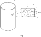
- FIG. 1 provides a schematic drawing of a cylinder liner 10 according to one embodiment, along with a drawing that magnifies and schematically illustrates an outer peripheral surface 11 of the cylinder liner 10.
- Plural projections 12 exist randomly on the cylinder liner outer peripheral surface 11.
- Two lines 13 and 13' each having a length of 15.2 mm and a thickness of 0.03 mm are set in parallel with a gap of 3.8 mm therebetween at an arbitrary position on the cylinder liner outer peripheral surface, and those projections that are in contact with either one of the lines 13 and 13' (projections indicated with hatched lines in FIG. 1 ) are counted.
- the number of the counted projections increases with narrower gaps between adjacent projections, or decreases with wider gaps between adjacent projections.
- the feature that the number of projections that are in contact with the two lines is 8 or less means that adjacent projections have moderate gaps therebetween and, by controlling adjacent projections to have such moderate gaps, a casting material poured into a mold is allowed to sufficiently spread between the projections, and the generation of voids on a cylinder block can thereby be inhibited, as a result of which the bonding strength between the cylinder liner and the cylinder block can be improved.
- the number of projections that are in contact with the lines in the above-described requirement (ii) may be 7 or less, or 5 or less. A lower limit thereof is not restricted; however, it is usually larger than 0, and may be 1 or larger, or 2 or larger.
- the number of projections in the requirement (ii) is preferably determined by counting the number of projections that are in contact with the two lines at two or more spots on the same cylinder liner and calculating the average thereof.
- FIG. 2 provides a schematic drawing of a cylinder liner 20 according to one embodiment, along with a drawing that magnifies and schematically illustrates the outer peripheral surface of the cylinder liner 20.
- Plural projections exist randomly on a cylinder liner outer peripheral surface 21. When one of these projections is defined as projection A, other projections are defined as A1 to A7 in ascending order of the distance from the projection A. Further, the distance between A and each An is defined as Ln, and the weighted average of the distance Ln is calculated.
- the equation of (iii) also means that adjacent projections have moderate gaps therebetween, and the weighted average of the distance Ln between projections is preferably not less than 1.5, and may be not less than 1.8, or not less than 2.0.
- An upper limit thereof is not restricted; however, it is usually 10 or less, and may be 5 or less, or 4 or less.
- the weighted average of the distance Ln between projections in the requirement (iii) is preferably determined by measuring the weighted average at two or more spots on the same cylinder liner and calculating the average thereof.
- the above (iv) represents the number and/or the thickness of the projections, indicating that the higher the projection area ratio, the greater the number of the projections and/or the larger the thickness of the projections.
- the projection area ratio S in the above-described range, gaps between the projections are moderately formed, so that a casting material poured into a mold spreads between the projections as well.
- the projection thickness (S/Pn), which is determined by dividing the projection area ratio S (%) by the number of projections Pn defined in the above (i), may be 0.45 or larger, 0.5 or larger, 0.55 or larger, or 0.6 or larger, but 0.8 or smaller, 0.75 or smaller, or 0.7 or smaller.
- a larger value of S/Pn indicates a larger thickness of the projections, and it is preferred to satisfy the above-described range since the bonding strength between the cylinder liner and a cylinder block is thereby improved.
- the above (v) represents the proportion of the projections having a constricted shape.
- a higher proportion of the projections having a constricted shape is more preferred since it leads to a further improvement in the bonding strength between the cylinder liner and a cylinder block.
- the projection constriction ratio Pr is preferably 50% or higher, and may be 60% or higher, 70% or higher, 75% or higher, or 80% or higher.
- FIG. 3 is an enlarged schematic cross-sectional view that illustrates one example of a projection having a constricted shape.
- FIG. 4 is an enlarged schematic cross-sectional view that illustrates one example of a projection having other shape with no constriction.
- a constricted projection has a height H from its base on the outer peripheral surface and, typically, the constricted projection has a minimum thickness B as the thickness gradually decreases in the height direction from the base surface. From this point, the thickness gradually increases in the height direction, giving the constricted projection a maximum thickness A.
- a projection which sequentially has a minimum thickness B and a maximum thickness A from its base surface along the height direction in this manner is defined as "constricted projection".
- the average projection height H (mm) is not particularly restricted; however, it is usually not less than 0.25 mm, preferably not less than 0.4 mm, but usually 1.1 mm or less, preferably 0.8 mm or less.
- the number of projections Pn per 1 cm 2 which is prescribed in the above (i) is determined by obtaining a contour plot of the projections at a position of 300 ⁇ m from the base of the projections using a three-dimensional laser measuring device, and counting the number of projections in a part enclosed in an area of 1 cm 2 .
- the projection area ratio S is determined by obtaining a contour plot of the projections at a position of 300 ⁇ m from the base of the projections using a three-dimensional laser measuring device, and calculating the ratio of a total area of the projections in a part enclosed in an area of 1 cm 2 with respect to a unit area (1 cm 2 ).
- the height of the projections can be determined using a dial depth gauge, and the numerical values prescribed in the above (ii) and (iii) can be measured or calculated by observing the cylinder liner surface under a microscope or an electron microscope.
- a projection having a constricted shape can be assessed by observation under a microscope. More specifically, a projection on the outer peripheral surface of a cylinder member is observed from an angle of about 45° with respect to a line that extends through a center point of the cylinder member and a measurement point of the outer peripheral surface. By this observation, the maximum thickness A, the minimum thickness B and the like of the projection can be determined. It is noted here that the term "projection thickness” used herein may be rephrased as "width of the observed projection”. An observation method will now be described more concretely referring to FIG 5 .
- a cylinder member 2 to be evaluated is arranged on a block stand 1.
- a microscope 3 connected to a TV monitor (not illustrated) is arranged diagonally above the cylinder member 2 to be evaluated, such that an optical axis M of the microscope 3 is aligned parallel to the vertical direction. Projections formed on the surface of the cylinder member 2 are observed in such a manner that the optical axis M of the microscope 3 and a line O, which extends through a center point of the cylinder member 2 and a measurement point of the outer peripheral surface, forms an angle of about 45° at an intersection of the optical axis M and the outer peripheral surface of the cylinder member 2.
- composition of a cast iron used as a material of the cylinder liner is not particularly restricted, and one typical example thereof is the following composition of flake graphite cast iron that takes into consideration the wear resistance, the seizure resistance and the workability and corresponds to JIS FC250:
- a method of producing the cylinder liner is not particularly restricted; however, a centrifugal casting method is preferred, and the method typically includes the following steps A to E.
- the step A is a step of preparing a suspension by blending a refractory base material, a binder, and water at a prescribed ratio.
- diatomaceous earth is typically used; however, the refractory base material is not restricted thereto.
- the content of diatomaceous earth in the suspension is usually 20% by mass to 35% by mass, and the average particle size of diatomaceous earth is usually 2 ⁇ m to 35 ⁇ m.
- bentonite is typically used; however, the binder is not restricted thereto.
- the content of bentonite in the suspension is usually 3% by mass to 9% by mass.
- the content of water in the suspension is usually 62% by mass to 78% by mass.
- the step B is a step of preparing a mold wash by adding a prescribed amount of a surfactant to the suspension prepared in the step A.
- the type of the surfactant is not particularly restricted, and a known surfactant, such as a cationic surfactant, an anionic surfactant, a nonionic surfactant or an amphoteric surfactant, may be used singly, or two or more thereof may be used in combination.
- the amount of the surfactant(s) to be added is usually 0.005 parts by mass to 0.04 parts by mass with respect to 100 parts by mass of the suspension.
- the step C is a step of applying the mold wash onto the inner peripheral surface of a cylindrical mold used as a casting mold.
- An application method is not particularly restricted; however, spray coating is typically employed.
- the mold wash it is preferred that the mold wash be applied in such a manner that a layer thereof is formed at a substantially uniform thickness over the entirety of the inner peripheral surface. Further, when the mold wash is applied to form a mold wash layer, it is preferred to provide a moderate centrifugal force by rotating the cylindrical mold.
- the present inventors presume that projections existing on the surface of the resulting cylinder liner are formed by the following process.
- the mold wash layer formed on the inner peripheral surface of the mold heated to a prescribed temperature bubbles are generated due to rapid evaporation of water contained in the mold wash.
- the surfactant acts on the bubbles of a relatively large size and the bubbles of a relatively small size bind to each other, whereby recessed holes are formed on the inner peripheral side of the mold wash layer.
- the recessed holes are formed on the mold wash layer in the process where the mold wash layer is gradually dried from the side of the mold inner peripheral surface and thereby gradually solidified to yield the recessed holes.
- the thickness of the mold wash layer is preferably selected to be in a range of 1.1 to 2.0 times the height of the projections; however, the thickness of the mold wash layer is not restricted thereto. In order to allow the mold wash layer to have such a thickness, it is preferred to control the temperature of the mold to be 300°C or lower.
- the step D is a step of casting cast iron into the mold which has the thus dried mold wash layer and is in a rotating state.
- molten cast iron is filled into the recessed holes having a constricted shape that are formed on the mold wash layer as described in the previous step, whereby constricted projections are formed on the surface of the resulting cylinder liner. Also in this process, it is preferred to apply a moderate centrifugal force.
- the step E is a step of taking the thus produced cylinder liner out of the mold and removing the mold wash layer from the cylinder liner surface by blasting to complete the cylinder liner.
- a cylinder liner is completed through the above-described steps.
- the projections on the cylinder liner surface are likely to be obtained in the desired form by adopting the followings:
- Gno represents the centrifugal force (G) provided by rotating the cylindrical mold in the formation of the mold wash layer in the step C
- Gno (casting) represents the centrifugal force (G) provided by rotating the mold in the step D.
- Another embodiment of the present invention is a method of producing a cylinder block, which method includes: a step of preparing a cylinder block mold; a step of arranging a cylinder liner in the thus prepared cylinder block mold; and a step of forming a cylinder block by pouring casting material into the cylinder block mold in which the cylinder liner has been arranged.
- the cylinder liner arranged in the cylinder block mold satisfies the above-described (i) and (ii).
- the projection height was measured at two sets of radially opposing spots on the respective axial ends of a cylinder member, and the average of the values measured at these four spots was calculated as the average height H (mm) of the projections.
- the number of projections Pn was determined by obtaining a 1 cm ⁇ 1 cm contour plot based on a measurement of the outer peripheral surface of a cylinder member using a noncontact-type three-dimensional laser measuring device, and subsequently counting the number of regions surrounded by a contour line indicating a height of 300 ⁇ m in the thus obtained contour plot. In the same manner as in the measurement of the projection height, the measurement was performed at two sets of radially opposing spots on the respective axial ends of the cylinder member, and the average of the values measured at these four spots was calculated the number of projections Pn per 1 cm 2 .
- the constriction ratio Pr (%) was determined by observing projections under a microscope (digital microscope KH-1300, manufactured by HIROX Co., Ltd.) to determine whether or not each projection was constricted, and subsequently dividing the number of constricted projections per 1 cm 2 by Pn and multiplying the thus obtained value by 100. It is noted here that the projection constriction ratio was defined as an average of the values measured at four spots.
- the projection area ratio S (%) was determined by obtaining a contour plot of projections at a position of 300 ⁇ m from the base of the projections using a three-dimensional laser measuring device, and calculating the ratio of a total area of the projections in a part enclosed in an area of 1 cm 2 with respect to a unit area (1 cm 2 ).
- the projection thickness (S/Pn) was determined by dividing this projection area ratio S (%) by the above-determined number of projections Pn.
- mold washes 1 to 3 were prepared.
- the surfactant shown in Table 1 a combination of an anionic surfactant having a hydrocarbon group and an acid ester group and an ethanol amide-type nonionic surfactant was used in the mold washes 1 and 3, while a combination of an anionic surfactant having a hydrocarbon group and an acid ester group and a POE alkyl ether-type nonionic surfactant was used in the mold wash 2.
- Mold wash Composition of mold wash Composition of suspension Surfactant (% by mass) Diatomaceous earth (% by mass) Average particle diameter (mm) Bentonite (% by mass) Water (% by mass) Mold wash 1 22 0.025 6 Balance 0.006 Mold wash 2 ⁇ ⁇ ⁇ Balance ⁇ Mold wash 3 ⁇ ⁇ ⁇ Balance 0.010
- Cylinder liners of Examples 1 and 2 and Comparative Example 1 were produced using the respective mold washes shown in Table 1.
- the temperature of the cylindrical mold in the step C was set in a range of 180°C to 300°C, and a mold wash layer was formed with a Gno (lining) of 55 G It is noted here, however, that the projection height was modified as appropriate by changing the thickness of the mold wash layer in each Example.
- the step D and the subsequent process were performed under the same conditions in both Examples, except that the casting of the cast iron was performed at a Gno (casting) of 120 G Thereafter, the inner peripheral surface of each of the thus obtained cast iron cylinder members was cut so as to adjust the thickness to be 5.5 mm.
- the cast iron cylinder members obtained in this manner had the following dimensions: an outer diameter (outer diameter including the projection height) of 85 mm, an inner diameter of 74 mm (thickness: 5.5 mm), and a length of 130 mm in the axial direction.
- the shapes of the projections of the thus produced cylinder liners are shown in Table 2.
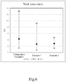
- the void ratio of the cylinder block was measured by the following method:
Landscapes
- Engineering & Computer Science (AREA)
- Mechanical Engineering (AREA)
- General Engineering & Computer Science (AREA)
- Chemical & Material Sciences (AREA)
- Combustion & Propulsion (AREA)
- Cylinder Crankcases Of Internal Combustion Engines (AREA)
- Pistons, Piston Rings, And Cylinders (AREA)
- Braking Arrangements (AREA)
- Mold Materials And Core Materials (AREA)
- Powder Metallurgy (AREA)
- Road Signs Or Road Markings (AREA)
Applications Claiming Priority (4)
| Application Number | Priority Date | Filing Date | Title |
|---|---|---|---|
| JP2018099656 | 2018-05-24 | ||
| JP2018203418 | 2018-10-30 | ||
| JP2018214320 | 2018-11-15 | ||
| PCT/JP2018/045644 WO2019225039A1 (fr) | 2018-05-24 | 2018-12-12 | Chemise de cylindre pour revêtement coulé et procédé de fabrication de bloc-cylindres |
Publications (3)
| Publication Number | Publication Date |
|---|---|
| EP3779162A1 true EP3779162A1 (fr) | 2021-02-17 |
| EP3779162A4 EP3779162A4 (fr) | 2022-02-16 |
| EP3779162B1 EP3779162B1 (fr) | 2023-05-10 |
Family
ID=66959900
Family Applications (2)
| Application Number | Title | Priority Date | Filing Date |
|---|---|---|---|
| EP18910238.7A Active EP3805545B1 (fr) | 2018-05-24 | 2018-12-12 | Élément cylindrique |
| EP18919906.0A Active EP3779162B1 (fr) | 2018-05-24 | 2018-12-12 | Chemise de cylindre pour revêtement coulé et procédé de fabrication de bloc-cylindres |
Family Applications Before (1)
| Application Number | Title | Priority Date | Filing Date |
|---|---|---|---|
| EP18910238.7A Active EP3805545B1 (fr) | 2018-05-24 | 2018-12-12 | Élément cylindrique |
Country Status (8)
| Country | Link |
|---|---|
| US (2) | US11168642B2 (fr) |
| EP (2) | EP3805545B1 (fr) |
| JP (3) | JP6655757B1 (fr) |
| KR (2) | KR102067371B1 (fr) |
| CN (4) | CN109915273B (fr) |
| BR (2) | BR112020018852B1 (fr) |
| PL (2) | PL3805545T3 (fr) |
| WO (2) | WO2019225039A1 (fr) |
Families Citing this family (8)
| Publication number | Priority date | Publication date | Assignee | Title |
|---|---|---|---|---|
| JP6655757B1 (ja) * | 2018-05-24 | 2020-02-26 | Tpr株式会社 | 鋳包み用シリンダライナ、及びシリンダブロックの製造方法 |
| WO2021221017A1 (fr) | 2020-04-28 | 2021-11-04 | Hoya株式会社 | Système endoscope |
| MX2021011117A (es) * | 2020-06-18 | 2022-01-31 | Tpr Co Ltd | Forro espinoso y metodo de fabricacion del mismo, y metodo de determinacion de la fuerza de adhesion. |
| EP3957415B1 (fr) * | 2020-06-24 | 2023-08-09 | Tpr Co., Ltd. | Chemise de cylindre pour coulage d'insert |
| JP7514799B2 (ja) * | 2021-06-09 | 2024-07-11 | Tpr株式会社 | シリンダライナ |
| US11536218B1 (en) * | 2021-10-14 | 2022-12-27 | Caterpillar Inc. | Method and system for a cylinder liner |
| DE102022105044A1 (de) | 2022-03-03 | 2023-09-07 | Bergmann Automotive GmbH | Reibring für eine Bremstrommel einer Trommelbremse eines Fahrzeugs, Bremstrommel einer Trommelbremse eines Fahrzeugs, Fahrzeug, Verwendung eines Reibrings für eine Bremstrommel einer Trommelbremse eines Fahrzeugs sowie Verfahren zur Herstellung eines Reibrings |
| CN119435227A (zh) * | 2024-11-14 | 2025-02-14 | 中原内配集团股份有限公司 | 一种毛刺状铸入式气缸套及其检测方法 |
Family Cites Families (17)
| Publication number | Priority date | Publication date | Assignee | Title |
|---|---|---|---|---|
| JPS5724666A (en) | 1980-07-18 | 1982-02-09 | Matsushita Electric Ind Co Ltd | Ultrasonic atomizer |
| KR100650352B1 (ko) * | 2002-05-13 | 2006-11-27 | 혼다 기켄 고교 가부시키가이샤 | 주철제 인서트 부재 및 그 제조 방법 |
| JP4429025B2 (ja) | 2004-01-09 | 2010-03-10 | トヨタ自動車株式会社 | 鋳包み用シリンダライナ |
| JP4452661B2 (ja) | 2005-07-08 | 2010-04-21 | トヨタ自動車株式会社 | 鋳ぐるみ用部品、シリンダブロック、鋳ぐるみ用部品被膜形成方法及びシリンダブロック製造方法 |
| JP2007016733A (ja) | 2005-07-08 | 2007-01-25 | Toyota Motor Corp | シリンダライナ及びエンジン |
| JP4512001B2 (ja) * | 2005-07-08 | 2010-07-28 | トヨタ自動車株式会社 | シリンダライナ、シリンダブロック及びシリンダライナ製造方法 |
| JP5388475B2 (ja) | 2008-04-30 | 2014-01-15 | Tpr株式会社 | 鋳包構造体 |
| JP5572847B2 (ja) * | 2010-03-17 | 2014-08-20 | 株式会社Moresco | シリンダライナ及びその製造方法 |
| JP2012067740A (ja) * | 2010-08-25 | 2012-04-05 | Tpr Co Ltd | 鋳包用シリンダライナ |
| JP6050628B2 (ja) * | 2012-07-23 | 2016-12-21 | 芦森工業株式会社 | 管路の内張り構造 |
| CN103016723B (zh) * | 2012-11-29 | 2016-08-03 | 广东肇庆动力金属股份有限公司 | 一种铝包容气缸套的制备方法 |
| WO2015002289A1 (fr) * | 2013-07-05 | 2015-01-08 | Tpr株式会社 | Arbres de corps rotatif, structure de corps rotatif et roue de véhicule |
| KR20170127903A (ko) * | 2016-05-13 | 2017-11-22 | 현대자동차주식회사 | 인서트 주조용 실린더 라이너 및 그 제조 방법 |
| JP6256524B2 (ja) * | 2016-05-17 | 2018-01-10 | スズキ株式会社 | 鋳包み用部材及びその製造方法 |
| CN106270370B (zh) * | 2016-08-10 | 2019-02-19 | 中原内配集团股份有限公司 | 一种针刺状气缸套及其制备方法 |
| WO2019097678A1 (fr) * | 2017-11-17 | 2019-05-23 | Tpr株式会社 | Élément cylindrique en fonte et structure composite |
| JP6655757B1 (ja) * | 2018-05-24 | 2020-02-26 | Tpr株式会社 | 鋳包み用シリンダライナ、及びシリンダブロックの製造方法 |
-
2018
- 2018-12-12 JP JP2019512838A patent/JP6655757B1/ja active Active
- 2018-12-12 JP JP2019510982A patent/JP6510743B1/ja active Active
- 2018-12-12 CN CN201811517010.7A patent/CN109915273B/zh active Active
- 2018-12-12 CN CN201811517031.9A patent/CN109944710B/zh active Active
- 2018-12-12 EP EP18910238.7A patent/EP3805545B1/fr active Active
- 2018-12-12 US US16/979,229 patent/US11168642B2/en active Active
- 2018-12-12 PL PL18910238.7T patent/PL3805545T3/pl unknown
- 2018-12-12 CN CN201822082014.9U patent/CN210178478U/zh not_active Expired - Fee Related
- 2018-12-12 EP EP18919906.0A patent/EP3779162B1/fr active Active
- 2018-12-12 WO PCT/JP2018/045644 patent/WO2019225039A1/fr not_active Ceased
- 2018-12-12 KR KR1020197032182A patent/KR102067371B1/ko active Active
- 2018-12-12 WO PCT/JP2018/045632 patent/WO2019225038A1/fr not_active Ceased
- 2018-12-12 KR KR1020207029960A patent/KR102231513B1/ko active Active
- 2018-12-12 US US16/491,135 patent/US10907570B2/en active Active
- 2018-12-12 PL PL18919906.0T patent/PL3779162T3/pl unknown
- 2018-12-12 BR BR112020018852-2A patent/BR112020018852B1/pt active IP Right Grant
- 2018-12-12 CN CN201822082034.6U patent/CN210483897U/zh active Active
- 2018-12-12 BR BR112019019322-7A patent/BR112019019322B1/pt active IP Right Grant
-
2019
- 2019-11-27 JP JP2019214004A patent/JP6705045B2/ja active Active
Also Published As
Similar Documents
| Publication | Publication Date | Title |
|---|---|---|
| EP3779162B1 (fr) | Chemise de cylindre pour revêtement coulé et procédé de fabrication de bloc-cylindres | |
| CN100406158C (zh) | 用于包心铸造的气缸套 | |
| EP3505271B1 (fr) | Élément cylindrique en fonte et structure composite | |
| CN214517524U (zh) | 铸造用气缸套筒 | |
| EP4170153A1 (fr) | Chemise striée, son procédé de fabrication, et procédé de discrimination de résistance d'assemblage | |
| JP7514799B2 (ja) | シリンダライナ | |
| CN111519088B (zh) | 铸铁件、含有铸铁件的复合部件以及铸铁件的制造方法 |
Legal Events
| Date | Code | Title | Description |
|---|---|---|---|
| STAA | Information on the status of an ep patent application or granted ep patent |
Free format text: STATUS: THE INTERNATIONAL PUBLICATION HAS BEEN MADE |
|
| PUAI | Public reference made under article 153(3) epc to a published international application that has entered the european phase |
Free format text: ORIGINAL CODE: 0009012 |
|
| STAA | Information on the status of an ep patent application or granted ep patent |
Free format text: STATUS: REQUEST FOR EXAMINATION WAS MADE |
|
| 17P | Request for examination filed |
Effective date: 20201029 |
|
| AK | Designated contracting states |
Kind code of ref document: A1 Designated state(s): AL AT BE BG CH CY CZ DE DK EE ES FI FR GB GR HR HU IE IS IT LI LT LU LV MC MK MT NL NO PL PT RO RS SE SI SK SM TR |
|
| AX | Request for extension of the european patent |
Extension state: BA ME |
|
| DAV | Request for validation of the european patent (deleted) | ||
| DAX | Request for extension of the european patent (deleted) | ||
| A4 | Supplementary search report drawn up and despatched |
Effective date: 20220119 |
|
| RIC1 | Information provided on ipc code assigned before grant |
Ipc: B22D 19/00 20060101ALI20220113BHEP Ipc: B22D 13/10 20060101ALI20220113BHEP Ipc: B22D 13/02 20060101ALI20220113BHEP Ipc: F02F 1/00 20060101AFI20220113BHEP |
|
| GRAP | Despatch of communication of intention to grant a patent |
Free format text: ORIGINAL CODE: EPIDOSNIGR1 |
|
| STAA | Information on the status of an ep patent application or granted ep patent |
Free format text: STATUS: GRANT OF PATENT IS INTENDED |
|
| INTG | Intention to grant announced |
Effective date: 20221201 |
|
| GRAS | Grant fee paid |
Free format text: ORIGINAL CODE: EPIDOSNIGR3 |
|
| GRAA | (expected) grant |
Free format text: ORIGINAL CODE: 0009210 |
|
| STAA | Information on the status of an ep patent application or granted ep patent |
Free format text: STATUS: THE PATENT HAS BEEN GRANTED |
|
| AK | Designated contracting states |
Kind code of ref document: B1 Designated state(s): AL AT BE BG CH CY CZ DE DK EE ES FI FR GB GR HR HU IE IS IT LI LT LU LV MC MK MT NL NO PL PT RO RS SE SI SK SM TR |
|
| REG | Reference to a national code |
Ref country code: GB Ref legal event code: FG4D |
|
| REG | Reference to a national code |
Ref country code: AT Ref legal event code: REF Ref document number: 1566890 Country of ref document: AT Kind code of ref document: T Effective date: 20230515 Ref country code: CH Ref legal event code: EP |
|
| REG | Reference to a national code |
Ref country code: DE Ref legal event code: R096 Ref document number: 602018049878 Country of ref document: DE |
|
| REG | Reference to a national code |
Ref country code: IE Ref legal event code: FG4D |
|
| REG | Reference to a national code |
Ref country code: LT Ref legal event code: MG9D |
|
| REG | Reference to a national code |
Ref country code: NL Ref legal event code: MP Effective date: 20230510 |
|
| REG | Reference to a national code |
Ref country code: AT Ref legal event code: MK05 Ref document number: 1566890 Country of ref document: AT Kind code of ref document: T Effective date: 20230510 |
|
| PG25 | Lapsed in a contracting state [announced via postgrant information from national office to epo] |
Ref country code: SE Free format text: LAPSE BECAUSE OF FAILURE TO SUBMIT A TRANSLATION OF THE DESCRIPTION OR TO PAY THE FEE WITHIN THE PRESCRIBED TIME-LIMIT Effective date: 20230510 Ref country code: PT Free format text: LAPSE BECAUSE OF FAILURE TO SUBMIT A TRANSLATION OF THE DESCRIPTION OR TO PAY THE FEE WITHIN THE PRESCRIBED TIME-LIMIT Effective date: 20230911 Ref country code: NO Free format text: LAPSE BECAUSE OF FAILURE TO SUBMIT A TRANSLATION OF THE DESCRIPTION OR TO PAY THE FEE WITHIN THE PRESCRIBED TIME-LIMIT Effective date: 20230810 Ref country code: NL Free format text: LAPSE BECAUSE OF FAILURE TO SUBMIT A TRANSLATION OF THE DESCRIPTION OR TO PAY THE FEE WITHIN THE PRESCRIBED TIME-LIMIT Effective date: 20230510 Ref country code: ES Free format text: LAPSE BECAUSE OF FAILURE TO SUBMIT A TRANSLATION OF THE DESCRIPTION OR TO PAY THE FEE WITHIN THE PRESCRIBED TIME-LIMIT Effective date: 20230510 Ref country code: AT Free format text: LAPSE BECAUSE OF FAILURE TO SUBMIT A TRANSLATION OF THE DESCRIPTION OR TO PAY THE FEE WITHIN THE PRESCRIBED TIME-LIMIT Effective date: 20230510 |
|
| PG25 | Lapsed in a contracting state [announced via postgrant information from national office to epo] |
Ref country code: RS Free format text: LAPSE BECAUSE OF FAILURE TO SUBMIT A TRANSLATION OF THE DESCRIPTION OR TO PAY THE FEE WITHIN THE PRESCRIBED TIME-LIMIT Effective date: 20230510 Ref country code: LV Free format text: LAPSE BECAUSE OF FAILURE TO SUBMIT A TRANSLATION OF THE DESCRIPTION OR TO PAY THE FEE WITHIN THE PRESCRIBED TIME-LIMIT Effective date: 20230510 Ref country code: LT Free format text: LAPSE BECAUSE OF FAILURE TO SUBMIT A TRANSLATION OF THE DESCRIPTION OR TO PAY THE FEE WITHIN THE PRESCRIBED TIME-LIMIT Effective date: 20230510 Ref country code: IS Free format text: LAPSE BECAUSE OF FAILURE TO SUBMIT A TRANSLATION OF THE DESCRIPTION OR TO PAY THE FEE WITHIN THE PRESCRIBED TIME-LIMIT Effective date: 20230910 Ref country code: HR Free format text: LAPSE BECAUSE OF FAILURE TO SUBMIT A TRANSLATION OF THE DESCRIPTION OR TO PAY THE FEE WITHIN THE PRESCRIBED TIME-LIMIT Effective date: 20230510 Ref country code: GR Free format text: LAPSE BECAUSE OF FAILURE TO SUBMIT A TRANSLATION OF THE DESCRIPTION OR TO PAY THE FEE WITHIN THE PRESCRIBED TIME-LIMIT Effective date: 20230811 |
|
| PG25 | Lapsed in a contracting state [announced via postgrant information from national office to epo] |
Ref country code: FI Free format text: LAPSE BECAUSE OF FAILURE TO SUBMIT A TRANSLATION OF THE DESCRIPTION OR TO PAY THE FEE WITHIN THE PRESCRIBED TIME-LIMIT Effective date: 20230510 |
|
| PG25 | Lapsed in a contracting state [announced via postgrant information from national office to epo] |
Ref country code: SK Free format text: LAPSE BECAUSE OF FAILURE TO SUBMIT A TRANSLATION OF THE DESCRIPTION OR TO PAY THE FEE WITHIN THE PRESCRIBED TIME-LIMIT Effective date: 20230510 |
|
| PG25 | Lapsed in a contracting state [announced via postgrant information from national office to epo] |
Ref country code: SM Free format text: LAPSE BECAUSE OF FAILURE TO SUBMIT A TRANSLATION OF THE DESCRIPTION OR TO PAY THE FEE WITHIN THE PRESCRIBED TIME-LIMIT Effective date: 20230510 Ref country code: SK Free format text: LAPSE BECAUSE OF FAILURE TO SUBMIT A TRANSLATION OF THE DESCRIPTION OR TO PAY THE FEE WITHIN THE PRESCRIBED TIME-LIMIT Effective date: 20230510 Ref country code: RO Free format text: LAPSE BECAUSE OF FAILURE TO SUBMIT A TRANSLATION OF THE DESCRIPTION OR TO PAY THE FEE WITHIN THE PRESCRIBED TIME-LIMIT Effective date: 20230510 Ref country code: EE Free format text: LAPSE BECAUSE OF FAILURE TO SUBMIT A TRANSLATION OF THE DESCRIPTION OR TO PAY THE FEE WITHIN THE PRESCRIBED TIME-LIMIT Effective date: 20230510 Ref country code: DK Free format text: LAPSE BECAUSE OF FAILURE TO SUBMIT A TRANSLATION OF THE DESCRIPTION OR TO PAY THE FEE WITHIN THE PRESCRIBED TIME-LIMIT Effective date: 20230510 Ref country code: CZ Free format text: LAPSE BECAUSE OF FAILURE TO SUBMIT A TRANSLATION OF THE DESCRIPTION OR TO PAY THE FEE WITHIN THE PRESCRIBED TIME-LIMIT Effective date: 20230510 |
|
| REG | Reference to a national code |
Ref country code: DE Ref legal event code: R097 Ref document number: 602018049878 Country of ref document: DE |
|
| PLBE | No opposition filed within time limit |
Free format text: ORIGINAL CODE: 0009261 |
|
| STAA | Information on the status of an ep patent application or granted ep patent |
Free format text: STATUS: NO OPPOSITION FILED WITHIN TIME LIMIT |
|
| 26N | No opposition filed |
Effective date: 20240213 |
|
| PG25 | Lapsed in a contracting state [announced via postgrant information from national office to epo] |
Ref country code: SI Free format text: LAPSE BECAUSE OF FAILURE TO SUBMIT A TRANSLATION OF THE DESCRIPTION OR TO PAY THE FEE WITHIN THE PRESCRIBED TIME-LIMIT Effective date: 20230510 |
|
| PG25 | Lapsed in a contracting state [announced via postgrant information from national office to epo] |
Ref country code: SI Free format text: LAPSE BECAUSE OF FAILURE TO SUBMIT A TRANSLATION OF THE DESCRIPTION OR TO PAY THE FEE WITHIN THE PRESCRIBED TIME-LIMIT Effective date: 20230510 |
|
| REG | Reference to a national code |
Ref country code: CH Ref legal event code: PL |
|
| PG25 | Lapsed in a contracting state [announced via postgrant information from national office to epo] |
Ref country code: LU Free format text: LAPSE BECAUSE OF NON-PAYMENT OF DUE FEES Effective date: 20231212 |
|
| PG25 | Lapsed in a contracting state [announced via postgrant information from national office to epo] |
Ref country code: MC Free format text: LAPSE BECAUSE OF FAILURE TO SUBMIT A TRANSLATION OF THE DESCRIPTION OR TO PAY THE FEE WITHIN THE PRESCRIBED TIME-LIMIT Effective date: 20230510 |
|
| GBPC | Gb: european patent ceased through non-payment of renewal fee |
Effective date: 20231212 |
|
| REG | Reference to a national code |
Ref country code: BE Ref legal event code: MM Effective date: 20231231 |
|
| PG25 | Lapsed in a contracting state [announced via postgrant information from national office to epo] |
Ref country code: MC Free format text: LAPSE BECAUSE OF FAILURE TO SUBMIT A TRANSLATION OF THE DESCRIPTION OR TO PAY THE FEE WITHIN THE PRESCRIBED TIME-LIMIT Effective date: 20230510 Ref country code: LU Free format text: LAPSE BECAUSE OF NON-PAYMENT OF DUE FEES Effective date: 20231212 |
|
| REG | Reference to a national code |
Ref country code: IE Ref legal event code: MM4A |
|
| PG25 | Lapsed in a contracting state [announced via postgrant information from national office to epo] |
Ref country code: IE Free format text: LAPSE BECAUSE OF NON-PAYMENT OF DUE FEES Effective date: 20231212 |
|
| PG25 | Lapsed in a contracting state [announced via postgrant information from national office to epo] |
Ref country code: GB Free format text: LAPSE BECAUSE OF NON-PAYMENT OF DUE FEES Effective date: 20231212 |
|
| PG25 | Lapsed in a contracting state [announced via postgrant information from national office to epo] |
Ref country code: BE Free format text: LAPSE BECAUSE OF NON-PAYMENT OF DUE FEES Effective date: 20231231 |
|
| PG25 | Lapsed in a contracting state [announced via postgrant information from national office to epo] |
Ref country code: CH Free format text: LAPSE BECAUSE OF NON-PAYMENT OF DUE FEES Effective date: 20231231 |
|
| PG25 | Lapsed in a contracting state [announced via postgrant information from national office to epo] |
Ref country code: IE Free format text: LAPSE BECAUSE OF NON-PAYMENT OF DUE FEES Effective date: 20231212 Ref country code: GB Free format text: LAPSE BECAUSE OF NON-PAYMENT OF DUE FEES Effective date: 20231212 Ref country code: CH Free format text: LAPSE BECAUSE OF NON-PAYMENT OF DUE FEES Effective date: 20231231 Ref country code: BE Free format text: LAPSE BECAUSE OF NON-PAYMENT OF DUE FEES Effective date: 20231231 |
|
| PG25 | Lapsed in a contracting state [announced via postgrant information from national office to epo] |
Ref country code: BG Free format text: LAPSE BECAUSE OF FAILURE TO SUBMIT A TRANSLATION OF THE DESCRIPTION OR TO PAY THE FEE WITHIN THE PRESCRIBED TIME-LIMIT Effective date: 20230510 |
|
| PG25 | Lapsed in a contracting state [announced via postgrant information from national office to epo] |
Ref country code: BG Free format text: LAPSE BECAUSE OF FAILURE TO SUBMIT A TRANSLATION OF THE DESCRIPTION OR TO PAY THE FEE WITHIN THE PRESCRIBED TIME-LIMIT Effective date: 20230510 |
|
| PG25 | Lapsed in a contracting state [announced via postgrant information from national office to epo] |
Ref country code: CY Free format text: LAPSE BECAUSE OF FAILURE TO SUBMIT A TRANSLATION OF THE DESCRIPTION OR TO PAY THE FEE WITHIN THE PRESCRIBED TIME-LIMIT; INVALID AB INITIO Effective date: 20181212 |
|
| PG25 | Lapsed in a contracting state [announced via postgrant information from national office to epo] |
Ref country code: HU Free format text: LAPSE BECAUSE OF FAILURE TO SUBMIT A TRANSLATION OF THE DESCRIPTION OR TO PAY THE FEE WITHIN THE PRESCRIBED TIME-LIMIT; INVALID AB INITIO Effective date: 20181212 |
|
| PGFP | Annual fee paid to national office [announced via postgrant information from national office to epo] |
Ref country code: FR Payment date: 20251222 Year of fee payment: 8 |
|
| PGFP | Annual fee paid to national office [announced via postgrant information from national office to epo] |
Ref country code: TR Payment date: 20251208 Year of fee payment: 8 |
|
| PGFP | Annual fee paid to national office [announced via postgrant information from national office to epo] |
Ref country code: PL Payment date: 20251202 Year of fee payment: 8 |
|
| PGFP | Annual fee paid to national office [announced via postgrant information from national office to epo] |
Ref country code: DE Payment date: 20251222 Year of fee payment: 8 |
|
| PGFP | Annual fee paid to national office [announced via postgrant information from national office to epo] |
Ref country code: IT Payment date: 20251231 Year of fee payment: 8 |