EP3779200B1 - Rotationsverdichter - Google Patents
Rotationsverdichter Download PDFInfo
- Publication number
- EP3779200B1 EP3779200B1 EP18912376.3A EP18912376A EP3779200B1 EP 3779200 B1 EP3779200 B1 EP 3779200B1 EP 18912376 A EP18912376 A EP 18912376A EP 3779200 B1 EP3779200 B1 EP 3779200B1
- Authority
- EP
- European Patent Office
- Prior art keywords
- oil supply
- supply hole
- roller
- compression mechanism
- rotary compression
- Prior art date
- Legal status (The legal status is an assumption and is not a legal conclusion. Google has not performed a legal analysis and makes no representation as to the accuracy of the status listed.)
- Active
Links
Images

Classifications
-
- F—MECHANICAL ENGINEERING; LIGHTING; HEATING; WEAPONS; BLASTING
- F04—POSITIVE - DISPLACEMENT MACHINES FOR LIQUIDS; PUMPS FOR LIQUIDS OR ELASTIC FLUIDS
- F04C—ROTARY-PISTON, OR OSCILLATING-PISTON, POSITIVE-DISPLACEMENT MACHINES FOR LIQUIDS; ROTARY-PISTON, OR OSCILLATING-PISTON, POSITIVE-DISPLACEMENT PUMPS
- F04C18/00—Rotary-piston pumps specially adapted for elastic fluids
- F04C18/30—Rotary-piston pumps specially adapted for elastic fluids having the characteristics covered by two or more of groups F04C18/02, F04C18/08, F04C18/22, F04C18/24, F04C18/48, or having the characteristics covered by one of these groups together with some other type of movement between co-operating members
- F04C18/34—Rotary-piston pumps specially adapted for elastic fluids having the characteristics covered by two or more of groups F04C18/02, F04C18/08, F04C18/22, F04C18/24, F04C18/48, or having the characteristics covered by one of these groups together with some other type of movement between co-operating members having the movement defined in group F04C18/08 or F04C18/22 and relative reciprocation between the co-operating members
- F04C18/356—Rotary-piston pumps specially adapted for elastic fluids having the characteristics covered by two or more of groups F04C18/02, F04C18/08, F04C18/22, F04C18/24, F04C18/48, or having the characteristics covered by one of these groups together with some other type of movement between co-operating members having the movement defined in group F04C18/08 or F04C18/22 and relative reciprocation between the co-operating members with vanes reciprocating with respect to the outer member
- F04C18/3562—Rotary-piston pumps specially adapted for elastic fluids having the characteristics covered by two or more of groups F04C18/02, F04C18/08, F04C18/22, F04C18/24, F04C18/48, or having the characteristics covered by one of these groups together with some other type of movement between co-operating members having the movement defined in group F04C18/08 or F04C18/22 and relative reciprocation between the co-operating members with vanes reciprocating with respect to the outer member the inner and outer member being in contact along one line or continuous surfaces substantially parallel to the axis of rotation
- F04C18/3564—Rotary-piston pumps specially adapted for elastic fluids having the characteristics covered by two or more of groups F04C18/02, F04C18/08, F04C18/22, F04C18/24, F04C18/48, or having the characteristics covered by one of these groups together with some other type of movement between co-operating members having the movement defined in group F04C18/08 or F04C18/22 and relative reciprocation between the co-operating members with vanes reciprocating with respect to the outer member the inner and outer member being in contact along one line or continuous surfaces substantially parallel to the axis of rotation the surfaces of the inner and outer member, forming the working space, being surfaces of revolution
-
- F—MECHANICAL ENGINEERING; LIGHTING; HEATING; WEAPONS; BLASTING
- F04—POSITIVE - DISPLACEMENT MACHINES FOR LIQUIDS; PUMPS FOR LIQUIDS OR ELASTIC FLUIDS
- F04C—ROTARY-PISTON, OR OSCILLATING-PISTON, POSITIVE-DISPLACEMENT MACHINES FOR LIQUIDS; ROTARY-PISTON, OR OSCILLATING-PISTON, POSITIVE-DISPLACEMENT PUMPS
- F04C23/00—Combinations of two or more pumps, each being of rotary-piston or oscillating-piston type, specially adapted for elastic fluids; Pumping installations specially adapted for elastic fluids; Multi-stage pumps specially adapted for elastic fluids
- F04C23/001—Combinations of two or more pumps, each being of rotary-piston or oscillating-piston type, specially adapted for elastic fluids; Pumping installations specially adapted for elastic fluids; Multi-stage pumps specially adapted for elastic fluids of similar working principle
-
- F—MECHANICAL ENGINEERING; LIGHTING; HEATING; WEAPONS; BLASTING
- F04—POSITIVE - DISPLACEMENT MACHINES FOR LIQUIDS; PUMPS FOR LIQUIDS OR ELASTIC FLUIDS
- F04C—ROTARY-PISTON, OR OSCILLATING-PISTON, POSITIVE-DISPLACEMENT MACHINES FOR LIQUIDS; ROTARY-PISTON, OR OSCILLATING-PISTON, POSITIVE-DISPLACEMENT PUMPS
- F04C23/00—Combinations of two or more pumps, each being of rotary-piston or oscillating-piston type, specially adapted for elastic fluids; Pumping installations specially adapted for elastic fluids; Multi-stage pumps specially adapted for elastic fluids
- F04C23/008—Hermetic pumps
-
- F—MECHANICAL ENGINEERING; LIGHTING; HEATING; WEAPONS; BLASTING
- F04—POSITIVE - DISPLACEMENT MACHINES FOR LIQUIDS; PUMPS FOR LIQUIDS OR ELASTIC FLUIDS
- F04C—ROTARY-PISTON, OR OSCILLATING-PISTON, POSITIVE-DISPLACEMENT MACHINES FOR LIQUIDS; ROTARY-PISTON, OR OSCILLATING-PISTON, POSITIVE-DISPLACEMENT PUMPS
- F04C29/00—Component parts, details or accessories of pumps or pumping installations, not provided for in groups F04C18/00 - F04C28/00
- F04C29/02—Lubrication; Lubricant separation
- F04C29/028—Means for improving or restricting lubricant flow
Definitions
- the present invention relates to a rotary compressor, and in particular to a rotary compressor of an internal intermediate pressure multi-stage (two stages) rotary compressor comprising first and second rotary compression elements in a sealed container.
- an internal intermediate pressure multi-stage (two stages) compression rotary compressor comprising first and second rotary compression elements has been known.
- Such a rotary compressor has a configuration including, in a sealed container, a drive motor and first and second rotary compression mechanisms that are driven with this drive motor.
- Refrigerant gas is taken into a low pressure chamber side of a cylinder through an intake port of the first rotary compression mechanism, and compressed by an operation of a roller and a vane to obtain an intermediate pressure, and the gas is discharged from a high pressure chamber side of the cylinder through a discharge port and a discharge muffler into the sealed container.
- the intermediate pressure refrigerant gas in this sealed container is taken into a low pressure chamber side of the cylinder through an intake port of the second rotary compression mechanism, and subjected to second stage compression by an operation of a roller and a vane. Resulting high-temperature high-pressure refrigerant gas is discharged from the high pressure chamber side to the outside.
- Patent Literature 2 relates to a so-called internal intermediate pressure multistage compression type rotary compressor making it possible to prevent the pressure inside a roller from inconveniently increasing and also to permit smooth and reliable supply of oil into a cylinder of a second rotary compressing element.
- a lubrication groove for providing communication between an oil bore and a low-pressure chamber in the cylinder is formed in a surface of an intermediate partitioner that is adjacent to the cylinder of the second rotary compressing element.
- a through bore for providing communication between a hermetically sealed vessel and the inside of the roller is formed in the intermediate partitioner.
- Patent Literature 3 relates to a rotary compressor comprising an electric element, and first and second rotary compression elements driven by the electric element. These components are provided in a hermetically sealed container. Gas compressed by the first rotary compression element is discharged into the hermetically sealed container, and the discharged gas of intermediate pressure is further compressed by the second rotary compression element wherein cylinders constitute the respective rotary compression elements. An intermediate diaphragm is provided between the cylinders to partition each rotary compression element.
- a support member is adapted to seal an opening surface of each cylinder and is provided with a bearing of a rotary shaft and an oil hole formed in the rotary shaft wherein the intermediate diaphragm includes an oil supply path for communicating the oil hole with a suction side of the second rotary compression element.
- Patent Literature 1 there is a problem that performance loss due to pressure bypass is generated in a process of returning oil separated in a rotary compressor.
- intermediate pressure oil in a sealed container is always supplied into compression chambers for improvement of sealability in a second stage compression chamber.
- the present invention has been developed in view of the above described respects, and an object of the present invention is to provide a rotary compressor in which an amount of oil to be supplied through an oil supply hole can be properly adjusted with a simple configuration.
- a rotary compressor as defined in claim 1 comprising, i.a. a sealed container, a drive motor, a first stage rotary compression mechanism and a second stage rotary compression mechanism that are rotated and driven by rotation of the drive motor, and an intermediate partition plate provided between the first stage rotary compression mechanism and the second stage rotary compression mechanism, wherein in the intermediate partition plate, an oil supply passage that extends from a center of the sealed container toward outside is provided, an oil supply hole that communicates between the oil supply passage and a second compression chamber of the second stage rotary compression mechanism is formed, and the oil supply hole is formed at a position to be opened where a second roller of the second stage rotary compression mechanism is at a position other than a compression stroke.
- the oil supply hole to be opened where the second roller is at the position other than the compression stroke is provided, and hence the oil supply hole can be held in an opened state or a closed state in accordance with a crank angle of the second roller. This makes it possible to adjust an amount of oil to be supplied through the oil supply hole.
- an oil supply hole is provided to be opened where a second roller is at a position other than a compression stroke, and hence the oil supply hole can be held in an opened state or a closed state in accordance with a crank angle of the second roller. This makes it possible to adjust an amount of oil to be supplied through the oil supply hole with a simple configuration.
- a rotary compressor comprises, in a sealed container, a drive motor, a first stage rotary compression mechanism and a second stage rotary compression mechanism that are rotated and driven by rotation of the drive motor, and an intermediate partition plate provided between the first stage rotary compression mechanism and the second stage rotary compression mechanism, wherein in the intermediate partition plate, an oil supply passage that extends from a center of the sealed container toward outside is provided, an oil supply hole that communicates between the oil supply passage and a second compression chamber of the second stage rotary compression mechanism is formed, and the oil supply hole is formed at a position to be opened where a second roller of the second stage rotary compression mechanism is at a position other than a compression stroke.
- the oil supply hole to be opened where the second roller is at the position other than the compression stroke is provided, and hence the oil supply hole can be held in an opened state or a closed state in accordance with a crank angle of the second roller. This makes it possible to adjust an amount of oil to be supplied through the oil supply hole with a simple configuration.
- the oil supply hole is provided in a range from 0° to 120° on a suction passage side from a position of a second vane of the second stage rotary compression mechanism so that the oil supply hole communicates at a crank angle of the second roller in a range from 60° to 350°.
- the oil supply hole is provided in the range from 0° to 120° on the suction passage side from the position of the second vane of the second stage rotary compression mechanism so that the oil supply hole communicates at the crank angle of the second roller in the range from 60° to 350°. Therefore, when the second roller is at the position other than the compression stroke, the oil supply hole can be opened. This makes it possible to adjust the amount of the oil to be supplied through the oil supply hole.
- Fig. 1 is a schematic vertical cross-sectional view showing the embodiment of a rotary compressor of the present invention.
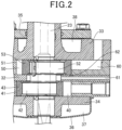
- Fig. 2 is an enlarged view of the rotary compressor.
- a rotary compressor 1 comprises a vertical cylindrical sealed container 10 made of a steel plate, and a lid body 11 is attached to an upper part of the sealed container 10.
- a drive motor 20 is contained in an upper part of an interior of the sealed container 10.
- a terminal 12 is attached to a center of an upper surface of the lid body 11, to supply power to the drive motor 20.
- the drive motor 20 comprises an annular stator 21 attached along an inner peripheral surface of an upper space of the sealed container 10, and a rotor 22 inserted and disposed inside the stator 21 with a gap.
- a rotary shaft 23 that extends in an axial direction of the sealed container 10 is attached to a center of the rotor 22.
- the stator 21 comprises a laminate body 24 made of laminated annular electromagnetic steel plates, and a stator coil 25 wound around the laminate body 24. Furthermore, the rotor 22 comprises a laminate body 26 made of laminated electromagnetic steel plates, and a permanent magnet 27 disposed in the laminate body 26.
- a first stage rotary compression mechanism 30 rotated and driven by the rotary shaft 23 of the drive motor 20 and a second stage rotary compression mechanism 31 located on an upper side are arranged.
- An intermediate partition plate 32 is disposed between the first stage rotary compression mechanism 30 and the second stage rotary compression mechanism 31.
- An upper support member 33 that closes an upper surface opening of the second stage rotary compression mechanism 31 is disposed above the second stage rotary compression mechanism 31, and a lower support member 34 that closes a lower surface opening of the first stage rotary compression mechanism 30 is disposed below the first stage rotary compression mechanism 30.
- the first stage rotary compression mechanism 30 comprises a first cylinder 41 including a first compression chamber 40 to compress a refrigerant therein, a first eccentric member 42 provided in the first cylinder 41, a first roller 43 fitted in the first eccentric member 42 to be eccentrically rotated, and a first vane that abuts on an outer peripheral surface of the first roller 43 to divide the first compression chamber 40 in the first cylinder 41 into a low pressure chamber side and a high pressure chamber side.
- the second stage rotary compression mechanism 31 comprises a second cylinder 51 including a second compression chamber 50 to compress the refrigerant therein, a second eccentric member 52 provided in the second cylinder 51, a second roller 53 fitted in the second eccentric member 52 to be eccentrically rotated, and a second vane 54 that abuts on an outer peripheral surface of the second roller 53 to divide the second compression chamber 50 in the second cylinder 51 into a low pressure chamber side and a high pressure chamber side.
- a suction passage (not shown) that communicates with interiors of the second cylinder 51 and first cylinder 41 in an unshown suction port is provided, and an upper cover 35 and a lower cover 36 are provided on an upper surface of the upper support member 33 and a lower surface of the lower support member 34, respectively.
- an intermediate pressure first stage discharge muffler 37 partially formed in a recess shape
- a high pressure second stage discharge muffler 38 is provided in the upper surface of the upper support member 33.
- a suction passage 60 is provided to communicate from the second compression chamber 50 to the interior of the sealed container 10.
- an oil supply passage 61 is formed to extend from a center of the sealed container 10 toward outside, and intermediate pressure oil is supplied to the oil supply passage 61.
- an oil supply hole 62 is formed to be opened in the second compression chamber 50 of the second stage rotary compression mechanism 31.
- the oil supply hole 62 is formed at a position to be opened where the second roller 53 is at a position other than a compression stroke.
- the oil supply hole 62 is provided in a range from 10° to 120° on a suction passage 60 side from the second vane 54.
- a distance of the oil supply hole 62 from a center of the rotary shaft 23 is also appropriately set.
- the oil supply hole 62 is formed at the position to be opened where the second roller 53 is at the position other than the compression stroke, because there is concern that the oil flows backward due to pressure of compression, if the oil supply hole 62 opens where the second roller 53 is at a position of the compression stroke.
- the angle of the oil supply hole 62 from the second vane 54 and the distance of the hole from the center of the rotary shaft 23 are set, so that even in a case where an eccentric amount of the second roller 53 varies, it is possible to set a period in which the oil supply hole 62 is opened while the second roller 53 rotates once.
- the oil supply hole 62 is provided in the range from 10° to 120° on the suction passage 60 side from the second vane 54, but this is not restrictive. That is, the oil supply hole is provided from 10° on the suction passage 60 side from the second vane 54, because in consideration of a width dimension of the second vane 54, the oil supply hole 62 cannot be formed at a position that overlaps with the second vane 54. Consequently, the position of the oil supply hole 62 may be set to a range from 0° to 10° in accordance with the width dimension of the second vane 54.
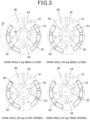
- Fig. 3 is a view showing an example where the oil supply hole 62 is formed at a position having a distance of 20 mm from the center of the rotary shaft 23 and an angle of 120° from the second vane 54.
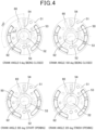
- Fig. 4 is a view showing an example where the oil supply hole 62 is formed at a position having a distance of 19.2 mm from the center of the rotary shaft 23 and an angle of 120° from the second vane 54.
- the oil supply hole 62 is closed in a case where the oil supply hole 62 is formed at the position having the distance of 20 mm from the center of the rotary shaft 23 and the angle of 120° from the second vane 54 and in a case where the crank angle of the second roller 53 is 0°. Even if the second roller 53 rotates to the crank angle of 180°, the oil supply hole 62 is closed.
- the oil supply hole 62 is closed. Even when the second roller 53 rotates to the crank angle of 180°, the oil supply hole 62 is closed, and when the crank angle of the second roller 53 is 285°, the oil supply hole 62 starts opening. Then, when the crank angle of the second roller 53 is 320°, the oil supply hole 62 finishes opening.
- the rotor 22 Upon driving of the drive motor 20, the rotor 22 is rotated, and the rotary shaft 23 is rotated and driven, so that the first roller 43 and the second roller 53 are eccentrically rotated.
- low pressure refrigerant gas taken into the first cylinder 41 is compressed by an operation of the first roller 43 and the first vane to obtain an intermediate pressure, and is discharged from the first cylinder 41 into the sealed container 10. In consequence, the gas obtains the intermediate pressure in the sealed container 10.
- the intermediate pressure refrigerant gas in the sealed container 10 is taken into the second cylinder 51, the taken intermediate pressure refrigerant gas is subjected to second stage compression by an operation of the second roller 53 and the second vane 54, and the resulting high-temperature high-pressure refrigerant gas is discharged.
- the oil mixed in the refrigerant gas flows into the oil supply passage 61 of the intermediate partition plate 32, and flows through the oil supply hole 62 into the second cylinder 51.
- the oil supply hole 62 is held in the opened state or a closed state in accordance with the crank angle of the second roller 53. Consequently, the oil supply hole 62 is not always opened, and hence an amount of oil to be supplied through the oil supply hole 62 can be properly adjusted.
- the rotary compressor comprises, in the sealed container 10, the drive motor 20, the first stage rotary compression mechanism 30 and the second stage rotary compression mechanism 31 that are rotated and driven by rotation of the drive motor 20, and the intermediate partition plate 32 provided between the first stage rotary compression mechanism 30 and the second stage rotary compression mechanism 31, wherein in the intermediate partition plate 32, the oil supply passage 61 that extends from the center of the sealed container 10 toward outside is provided, the oil supply hole 62 that communicates between the oil supply passage 61 and the second compression chamber 50 of the second stage rotary compression mechanism 31 is formed, and the oil supply hole 62 is formed at the position to be opened where the second roller 53 of the second stage rotary compression mechanism 31 is at the position other than the compression stroke.
- the oil supply hole 62 to be opened where the second roller 53 is at the position other than the compression stroke is provided, and hence the oil supply hole 62 can be held in the opened state or the closed state in accordance with the crank angle of the second roller 53. This makes it possible to adjust the amount of the oil to be supplied through the oil supply hole 62.
- the oil supply hole 62 is provided in a range from 0° to 120° on a suction passage 60 side from a position of the second vane 54 of the second stage rotary compression mechanism 31 so that the oil supply hole communicates at the crank angle of the second roller 53 in a range from 60° to 350°.
- the oil supply hole 62 is provided in the range from 0° to 120° on the suction passage 60 side from the position of the second vane 54 of the second stage rotary compression mechanism 31 so that the oil supply hole communicates at the crank angle of the second roller 53 in the range from 60° to 350°. Therefore, when the second roller 53 is at the position other than the compression stroke, the oil supply hole 62 can be opened. This makes it possible to adjust the amount of the oil to be supplied through the oil supply hole 62.
- an oil supply hole can be held in an opened state or a closed state in accordance with a crank angle of a second roller, and an amount of oil to be supplied through the oil supply hole can be adjusted with a simple configuration. Consequently, the invention is suitable as a rotary compressor.
Landscapes
- Engineering & Computer Science (AREA)
- Mechanical Engineering (AREA)
- General Engineering & Computer Science (AREA)
- Applications Or Details Of Rotary Compressors (AREA)
Claims (1)
- Rotationsverdichter, umfassendeinen abgedichteten Behälter (10),einen Antriebsmotor (20),einen Rotationsverdichtungsmechanismus der ersten Stufe (30) mit einer ersten Walze (43) und einem ersten Schieber (44), undeinen Rotationsverdichtungsmechanismus der zweiten Stufe (31) mit einer zweiten Walze (53) und einem zweiten Schieber (54), die durch Drehung des Antriebsmotors gedreht und angetrieben werden, undeine Zwischenunterteilungsplatte (32), die zwischen dem Rotationsverdichtungsmechanismus der ersten Stufe und dem Rotationsverdichtungsmechanismus der zweiten Stufe vorgesehen ist,wobei in der Zwischenunterteilungsplatte ein Ölzuführkanal (61), der von einer Mitte des abgedichteten Behälters nach außen verläuft, vorgesehen ist, eine Ölzuführbohrung (62) ausgebildet ist, die eine Verbindung zwischen dem Ölzuführkanal und einer zweiten Verdichtungskammer (50) des Rotationsverdichtungsmechanismus der zweiten Stufe herstellt,die Ölzuführbohrung (62) an einer zu öffnenden Stelle ausgebildet ist, wo sich die zweite Walze (53) des Rotationsverdichtungsmechanismus der zweiten Stufe (31) an einer anderen Position als einem Verdichtungshub befindet,dadurch gekennzeichnet, dassdie Ölzuführbohrung (62) an einer Position von 120° auf einer Saugkanalseite von einer Position des zweiten Trennschiebers (54) des Rotationsverdichtungsmechanismus der zweiten Stufe (31) vorgesehen ist, sodass die Ölzuführbohrung (62) bei einem Kurbelwinkel der zweiten Walze (53) im Bereich von 245° bis 350° eine Verbindung herstellt.
Applications Claiming Priority (2)
| Application Number | Priority Date | Filing Date | Title |
|---|---|---|---|
| JP2018063470 | 2018-03-29 | ||
| PCT/JP2018/038727 WO2019187272A1 (ja) | 2018-03-29 | 2018-10-17 | ロータリコンプレッサ |
Publications (3)
| Publication Number | Publication Date |
|---|---|
| EP3779200A1 EP3779200A1 (de) | 2021-02-17 |
| EP3779200A4 EP3779200A4 (de) | 2021-05-19 |
| EP3779200B1 true EP3779200B1 (de) | 2024-09-18 |
Family
ID=68061063
Family Applications (1)
| Application Number | Title | Priority Date | Filing Date |
|---|---|---|---|
| EP18912376.3A Active EP3779200B1 (de) | 2018-03-29 | 2018-10-17 | Rotationsverdichter |
Country Status (2)
| Country | Link |
|---|---|
| EP (1) | EP3779200B1 (de) |
| WO (1) | WO2019187272A1 (de) |
Families Citing this family (2)
| Publication number | Priority date | Publication date | Assignee | Title |
|---|---|---|---|---|
| CN111720312B (zh) * | 2020-06-18 | 2022-08-19 | 广东美芝制冷设备有限公司 | 旋转压缩机和制冷循环系统 |
| CN121066831A (zh) * | 2025-10-13 | 2025-12-05 | 珠海凌达压缩机有限公司 | 一种隔板油路循环机构及其压缩机 |
Family Cites Families (5)
| Publication number | Priority date | Publication date | Assignee | Title |
|---|---|---|---|---|
| US7128540B2 (en) * | 2001-09-27 | 2006-10-31 | Sanyo Electric Co., Ltd. | Refrigeration system having a rotary compressor |
| JP3935854B2 (ja) * | 2003-03-25 | 2007-06-27 | 三洋電機株式会社 | ロータリコンプレッサ |
| US7223082B2 (en) * | 2003-03-25 | 2007-05-29 | Sanyo Electric Co., Ltd. | Rotary compressor |
| JP5764733B2 (ja) | 2010-09-29 | 2015-08-19 | パナソニックIpマネジメント株式会社 | ロータリコンプレッサ及びその製造方法 |
| JP2018063470A (ja) | 2016-10-11 | 2018-04-19 | 富士通株式会社 | 制御装置および制御方法 |
-
2018
- 2018-10-17 EP EP18912376.3A patent/EP3779200B1/de active Active
- 2018-10-17 WO PCT/JP2018/038727 patent/WO2019187272A1/ja not_active Ceased
Also Published As
| Publication number | Publication date |
|---|---|
| WO2019187272A1 (ja) | 2019-10-03 |
| EP3779200A1 (de) | 2021-02-17 |
| EP3779200A4 (de) | 2021-05-19 |
Similar Documents
| Publication | Publication Date | Title |
|---|---|---|
| JP6187266B2 (ja) | 電動圧縮機 | |
| EP2177768B1 (de) | Mehrstufiger verdichter | |
| EP1703132B1 (de) | Flügelzellenverdichter | |
| EP2520803B1 (de) | Verdichter | |
| EP2551526B1 (de) | Zweistufiger Drehkompressor | |
| KR101099923B1 (ko) | 스크롤형 압축기 | |
| EP3214263B1 (de) | Hermetischer zwei-zylinder-verdichter | |
| EP3584443B1 (de) | Verdichter | |
| KR101861005B1 (ko) | 베인형 압축기 | |
| EP3992460A1 (de) | Spiralverdichter | |
| EP3951181B1 (de) | Rotationsverdichter | |
| EP3617514B1 (de) | Zweistufig verdichtender kompressor, vom typ interner mittlerer druck | |
| KR101157266B1 (ko) | 로터리 콤프레셔 | |
| EP3779200A1 (de) | Rotationsverdichter | |
| US9885359B2 (en) | Motor-driven compressor | |
| KR101909606B1 (ko) | 스크롤 압축기 | |
| US20110236245A1 (en) | Rotary compressor | |
| US20070048151A1 (en) | Closed electric compressor | |
| KR20030051086A (ko) | 회전식 트윈 압축기의 흡입장치 | |
| KR100556970B1 (ko) | 회전식 트윈압축기의 토출장치 | |
| EP3572670B1 (de) | Spiralverdichter | |
| JP2010048146A (ja) | インバータ一体型電動圧縮機 | |
| KR101380987B1 (ko) | 로터리식 압축기 | |
| JP5075534B2 (ja) | ロータリコンプレッサの製造方法 | |
| JP2011074814A (ja) | ロータリコンプレッサ及びその製造方法 |
Legal Events
| Date | Code | Title | Description |
|---|---|---|---|
| STAA | Information on the status of an ep patent application or granted ep patent |
Free format text: STATUS: THE INTERNATIONAL PUBLICATION HAS BEEN MADE |
|
| PUAI | Public reference made under article 153(3) epc to a published international application that has entered the european phase |
Free format text: ORIGINAL CODE: 0009012 |
|
| STAA | Information on the status of an ep patent application or granted ep patent |
Free format text: STATUS: REQUEST FOR EXAMINATION WAS MADE |
|
| 17P | Request for examination filed |
Effective date: 20201029 |
|
| AK | Designated contracting states |
Kind code of ref document: A1 Designated state(s): AL AT BE BG CH CY CZ DE DK EE ES FI FR GB GR HR HU IE IS IT LI LT LU LV MC MK MT NL NO PL PT RO RS SE SI SK SM TR |
|
| AX | Request for extension of the european patent |
Extension state: BA ME |
|
| A4 | Supplementary search report drawn up and despatched |
Effective date: 20210419 |
|
| RIC1 | Information provided on ipc code assigned before grant |
Ipc: F04C 29/02 20060101AFI20210413BHEP Ipc: F04C 18/356 20060101ALI20210413BHEP Ipc: F04C 23/00 20060101ALI20210413BHEP |
|
| DAV | Request for validation of the european patent (deleted) | ||
| DAX | Request for extension of the european patent (deleted) | ||
| GRAP | Despatch of communication of intention to grant a patent |
Free format text: ORIGINAL CODE: EPIDOSNIGR1 |
|
| STAA | Information on the status of an ep patent application or granted ep patent |
Free format text: STATUS: GRANT OF PATENT IS INTENDED |
|
| INTG | Intention to grant announced |
Effective date: 20230414 |
|
| GRAJ | Information related to disapproval of communication of intention to grant by the applicant or resumption of examination proceedings by the epo deleted |
Free format text: ORIGINAL CODE: EPIDOSDIGR1 |
|
| STAA | Information on the status of an ep patent application or granted ep patent |
Free format text: STATUS: REQUEST FOR EXAMINATION WAS MADE |
|
| STAA | Information on the status of an ep patent application or granted ep patent |
Free format text: STATUS: EXAMINATION IS IN PROGRESS |
|
| INTC | Intention to grant announced (deleted) | ||
| 17Q | First examination report despatched |
Effective date: 20230828 |
|
| GRAP | Despatch of communication of intention to grant a patent |
Free format text: ORIGINAL CODE: EPIDOSNIGR1 |
|
| STAA | Information on the status of an ep patent application or granted ep patent |
Free format text: STATUS: GRANT OF PATENT IS INTENDED |
|
| INTG | Intention to grant announced |
Effective date: 20240415 |
|
| GRAS | Grant fee paid |
Free format text: ORIGINAL CODE: EPIDOSNIGR3 |
|
| GRAA | (expected) grant |
Free format text: ORIGINAL CODE: 0009210 |
|
| STAA | Information on the status of an ep patent application or granted ep patent |
Free format text: STATUS: THE PATENT HAS BEEN GRANTED |
|
| AK | Designated contracting states |
Kind code of ref document: B1 Designated state(s): AL AT BE BG CH CY CZ DE DK EE ES FI FR GB GR HR HU IE IS IT LI LT LU LV MC MK MT NL NO PL PT RO RS SE SI SK SM TR |
|
| REG | Reference to a national code |
Ref country code: GB Ref legal event code: FG4D |
|
| REG | Reference to a national code |
Ref country code: CH Ref legal event code: EP |
|
| REG | Reference to a national code |
Ref country code: DE Ref legal event code: R096 Ref document number: 602018074613 Country of ref document: DE |
|
| REG | Reference to a national code |
Ref country code: IE Ref legal event code: FG4D |
|
| REG | Reference to a national code |
Ref country code: LT Ref legal event code: MG9D |
|
| PG25 | Lapsed in a contracting state [announced via postgrant information from national office to epo] |
Ref country code: NO Free format text: LAPSE BECAUSE OF FAILURE TO SUBMIT A TRANSLATION OF THE DESCRIPTION OR TO PAY THE FEE WITHIN THE PRESCRIBED TIME-LIMIT Effective date: 20241218 |
|
| PG25 | Lapsed in a contracting state [announced via postgrant information from national office to epo] |
Ref country code: GR Free format text: LAPSE BECAUSE OF FAILURE TO SUBMIT A TRANSLATION OF THE DESCRIPTION OR TO PAY THE FEE WITHIN THE PRESCRIBED TIME-LIMIT Effective date: 20241219 Ref country code: FI Free format text: LAPSE BECAUSE OF FAILURE TO SUBMIT A TRANSLATION OF THE DESCRIPTION OR TO PAY THE FEE WITHIN THE PRESCRIBED TIME-LIMIT Effective date: 20240918 |
|
| PG25 | Lapsed in a contracting state [announced via postgrant information from national office to epo] |
Ref country code: BG Free format text: LAPSE BECAUSE OF FAILURE TO SUBMIT A TRANSLATION OF THE DESCRIPTION OR TO PAY THE FEE WITHIN THE PRESCRIBED TIME-LIMIT Effective date: 20240918 |
|
| PG25 | Lapsed in a contracting state [announced via postgrant information from national office to epo] |
Ref country code: LV Free format text: LAPSE BECAUSE OF FAILURE TO SUBMIT A TRANSLATION OF THE DESCRIPTION OR TO PAY THE FEE WITHIN THE PRESCRIBED TIME-LIMIT Effective date: 20240918 |
|
| PG25 | Lapsed in a contracting state [announced via postgrant information from national office to epo] |
Ref country code: HR Free format text: LAPSE BECAUSE OF FAILURE TO SUBMIT A TRANSLATION OF THE DESCRIPTION OR TO PAY THE FEE WITHIN THE PRESCRIBED TIME-LIMIT Effective date: 20240918 |
|
| REG | Reference to a national code |
Ref country code: NL Ref legal event code: MP Effective date: 20240918 |
|
| PG25 | Lapsed in a contracting state [announced via postgrant information from national office to epo] |
Ref country code: RS Free format text: LAPSE BECAUSE OF FAILURE TO SUBMIT A TRANSLATION OF THE DESCRIPTION OR TO PAY THE FEE WITHIN THE PRESCRIBED TIME-LIMIT Effective date: 20241218 |
|
| PG25 | Lapsed in a contracting state [announced via postgrant information from national office to epo] |
Ref country code: RS Free format text: LAPSE BECAUSE OF FAILURE TO SUBMIT A TRANSLATION OF THE DESCRIPTION OR TO PAY THE FEE WITHIN THE PRESCRIBED TIME-LIMIT Effective date: 20241218 Ref country code: NO Free format text: LAPSE BECAUSE OF FAILURE TO SUBMIT A TRANSLATION OF THE DESCRIPTION OR TO PAY THE FEE WITHIN THE PRESCRIBED TIME-LIMIT Effective date: 20241218 Ref country code: LV Free format text: LAPSE BECAUSE OF FAILURE TO SUBMIT A TRANSLATION OF THE DESCRIPTION OR TO PAY THE FEE WITHIN THE PRESCRIBED TIME-LIMIT Effective date: 20240918 Ref country code: HR Free format text: LAPSE BECAUSE OF FAILURE TO SUBMIT A TRANSLATION OF THE DESCRIPTION OR TO PAY THE FEE WITHIN THE PRESCRIBED TIME-LIMIT Effective date: 20240918 Ref country code: GR Free format text: LAPSE BECAUSE OF FAILURE TO SUBMIT A TRANSLATION OF THE DESCRIPTION OR TO PAY THE FEE WITHIN THE PRESCRIBED TIME-LIMIT Effective date: 20241219 Ref country code: FI Free format text: LAPSE BECAUSE OF FAILURE TO SUBMIT A TRANSLATION OF THE DESCRIPTION OR TO PAY THE FEE WITHIN THE PRESCRIBED TIME-LIMIT Effective date: 20240918 Ref country code: BG Free format text: LAPSE BECAUSE OF FAILURE TO SUBMIT A TRANSLATION OF THE DESCRIPTION OR TO PAY THE FEE WITHIN THE PRESCRIBED TIME-LIMIT Effective date: 20240918 |
|
| REG | Reference to a national code |
Ref country code: AT Ref legal event code: MK05 Ref document number: 1724890 Country of ref document: AT Kind code of ref document: T Effective date: 20240918 |
|
| PG25 | Lapsed in a contracting state [announced via postgrant information from national office to epo] |
Ref country code: NL Free format text: LAPSE BECAUSE OF FAILURE TO SUBMIT A TRANSLATION OF THE DESCRIPTION OR TO PAY THE FEE WITHIN THE PRESCRIBED TIME-LIMIT Effective date: 20240918 |
|
| PG25 | Lapsed in a contracting state [announced via postgrant information from national office to epo] |
Ref country code: PT Free format text: LAPSE BECAUSE OF FAILURE TO SUBMIT A TRANSLATION OF THE DESCRIPTION OR TO PAY THE FEE WITHIN THE PRESCRIBED TIME-LIMIT Effective date: 20250120 Ref country code: IS Free format text: LAPSE BECAUSE OF FAILURE TO SUBMIT A TRANSLATION OF THE DESCRIPTION OR TO PAY THE FEE WITHIN THE PRESCRIBED TIME-LIMIT Effective date: 20250118 |
|
| PG25 | Lapsed in a contracting state [announced via postgrant information from national office to epo] |
Ref country code: RO Free format text: LAPSE BECAUSE OF FAILURE TO SUBMIT A TRANSLATION OF THE DESCRIPTION OR TO PAY THE FEE WITHIN THE PRESCRIBED TIME-LIMIT Effective date: 20240918 Ref country code: SM Free format text: LAPSE BECAUSE OF FAILURE TO SUBMIT A TRANSLATION OF THE DESCRIPTION OR TO PAY THE FEE WITHIN THE PRESCRIBED TIME-LIMIT Effective date: 20240918 |
|
| PG25 | Lapsed in a contracting state [announced via postgrant information from national office to epo] |
Ref country code: ES Free format text: LAPSE BECAUSE OF FAILURE TO SUBMIT A TRANSLATION OF THE DESCRIPTION OR TO PAY THE FEE WITHIN THE PRESCRIBED TIME-LIMIT Effective date: 20240918 |
|
| PG25 | Lapsed in a contracting state [announced via postgrant information from national office to epo] |
Ref country code: EE Free format text: LAPSE BECAUSE OF FAILURE TO SUBMIT A TRANSLATION OF THE DESCRIPTION OR TO PAY THE FEE WITHIN THE PRESCRIBED TIME-LIMIT Effective date: 20240918 Ref country code: AT Free format text: LAPSE BECAUSE OF FAILURE TO SUBMIT A TRANSLATION OF THE DESCRIPTION OR TO PAY THE FEE WITHIN THE PRESCRIBED TIME-LIMIT Effective date: 20240918 |
|
| PG25 | Lapsed in a contracting state [announced via postgrant information from national office to epo] |
Ref country code: CZ Free format text: LAPSE BECAUSE OF FAILURE TO SUBMIT A TRANSLATION OF THE DESCRIPTION OR TO PAY THE FEE WITHIN THE PRESCRIBED TIME-LIMIT Effective date: 20240918 Ref country code: PL Free format text: LAPSE BECAUSE OF FAILURE TO SUBMIT A TRANSLATION OF THE DESCRIPTION OR TO PAY THE FEE WITHIN THE PRESCRIBED TIME-LIMIT Effective date: 20240918 |
|
| PG25 | Lapsed in a contracting state [announced via postgrant information from national office to epo] |
Ref country code: SK Free format text: LAPSE BECAUSE OF FAILURE TO SUBMIT A TRANSLATION OF THE DESCRIPTION OR TO PAY THE FEE WITHIN THE PRESCRIBED TIME-LIMIT Effective date: 20240918 Ref country code: IT Free format text: LAPSE BECAUSE OF FAILURE TO SUBMIT A TRANSLATION OF THE DESCRIPTION OR TO PAY THE FEE WITHIN THE PRESCRIBED TIME-LIMIT Effective date: 20240918 |
|
| REG | Reference to a national code |
Ref country code: CH Ref legal event code: PL |
|
| REG | Reference to a national code |
Ref country code: DE Ref legal event code: R097 Ref document number: 602018074613 Country of ref document: DE |
|
| PG25 | Lapsed in a contracting state [announced via postgrant information from national office to epo] |
Ref country code: MC Free format text: LAPSE BECAUSE OF FAILURE TO SUBMIT A TRANSLATION OF THE DESCRIPTION OR TO PAY THE FEE WITHIN THE PRESCRIBED TIME-LIMIT Effective date: 20240918 |
|
| PG25 | Lapsed in a contracting state [announced via postgrant information from national office to epo] |
Ref country code: DK Free format text: LAPSE BECAUSE OF FAILURE TO SUBMIT A TRANSLATION OF THE DESCRIPTION OR TO PAY THE FEE WITHIN THE PRESCRIBED TIME-LIMIT Effective date: 20240918 |
|
| PG25 | Lapsed in a contracting state [announced via postgrant information from national office to epo] |
Ref country code: LU Free format text: LAPSE BECAUSE OF NON-PAYMENT OF DUE FEES Effective date: 20241017 Ref country code: BE Free format text: LAPSE BECAUSE OF NON-PAYMENT OF DUE FEES Effective date: 20241031 |
|
| PG25 | Lapsed in a contracting state [announced via postgrant information from national office to epo] |
Ref country code: CH Free format text: LAPSE BECAUSE OF NON-PAYMENT OF DUE FEES Effective date: 20241031 |
|
| PLBE | No opposition filed within time limit |
Free format text: ORIGINAL CODE: 0009261 |
|
| STAA | Information on the status of an ep patent application or granted ep patent |
Free format text: STATUS: NO OPPOSITION FILED WITHIN TIME LIMIT |
|
| REG | Reference to a national code |
Ref country code: BE Ref legal event code: MM Effective date: 20241031 |
|
| 26N | No opposition filed |
Effective date: 20250619 |
|
| GBPC | Gb: european patent ceased through non-payment of renewal fee |
Effective date: 20241218 |
|
| PG25 | Lapsed in a contracting state [announced via postgrant information from national office to epo] |
Ref country code: SE Free format text: LAPSE BECAUSE OF FAILURE TO SUBMIT A TRANSLATION OF THE DESCRIPTION OR TO PAY THE FEE WITHIN THE PRESCRIBED TIME-LIMIT Effective date: 20240918 |
|
| PG25 | Lapsed in a contracting state [announced via postgrant information from national office to epo] |
Ref country code: GB Free format text: LAPSE BECAUSE OF NON-PAYMENT OF DUE FEES Effective date: 20241218 |
|
| PG25 | Lapsed in a contracting state [announced via postgrant information from national office to epo] |
Ref country code: FR Free format text: LAPSE BECAUSE OF NON-PAYMENT OF DUE FEES Effective date: 20241118 |
|
| PG25 | Lapsed in a contracting state [announced via postgrant information from national office to epo] |
Ref country code: IE Free format text: LAPSE BECAUSE OF NON-PAYMENT OF DUE FEES Effective date: 20241017 |
|
| PGFP | Annual fee paid to national office [announced via postgrant information from national office to epo] |
Ref country code: DE Payment date: 20251021 Year of fee payment: 8 |
|
| PG25 | Lapsed in a contracting state [announced via postgrant information from national office to epo] |
Ref country code: CY Free format text: LAPSE BECAUSE OF FAILURE TO SUBMIT A TRANSLATION OF THE DESCRIPTION OR TO PAY THE FEE WITHIN THE PRESCRIBED TIME-LIMIT; INVALID AB INITIO Effective date: 20181017 |
|
| PG25 | Lapsed in a contracting state [announced via postgrant information from national office to epo] |
Ref country code: HU Free format text: LAPSE BECAUSE OF FAILURE TO SUBMIT A TRANSLATION OF THE DESCRIPTION OR TO PAY THE FEE WITHIN THE PRESCRIBED TIME-LIMIT; INVALID AB INITIO Effective date: 20181017 |
|
| PG25 | Lapsed in a contracting state [announced via postgrant information from national office to epo] |
Ref country code: TR Free format text: LAPSE BECAUSE OF FAILURE TO SUBMIT A TRANSLATION OF THE DESCRIPTION OR TO PAY THE FEE WITHIN THE PRESCRIBED TIME-LIMIT Effective date: 20240918 |
|
| PG25 | Lapsed in a contracting state [announced via postgrant information from national office to epo] |
Ref country code: SI Free format text: LAPSE BECAUSE OF FAILURE TO SUBMIT A TRANSLATION OF THE DESCRIPTION OR TO PAY THE FEE WITHIN THE PRESCRIBED TIME-LIMIT Effective date: 20240918 |
|
| PG25 | Lapsed in a contracting state [announced via postgrant information from national office to epo] |
Ref country code: LT Free format text: LAPSE BECAUSE OF FAILURE TO SUBMIT A TRANSLATION OF THE DESCRIPTION OR TO PAY THE FEE WITHIN THE PRESCRIBED TIME-LIMIT Effective date: 20240918 |