EP3779340A1 - Dispositif de séchage portable pour installations de peinture - Google Patents
Dispositif de séchage portable pour installations de peinture Download PDFInfo
- Publication number
- EP3779340A1 EP3779340A1 EP20190229.3A EP20190229A EP3779340A1 EP 3779340 A1 EP3779340 A1 EP 3779340A1 EP 20190229 A EP20190229 A EP 20190229A EP 3779340 A1 EP3779340 A1 EP 3779340A1
- Authority
- EP
- European Patent Office
- Prior art keywords
- drying device
- arm
- blower
- nozzle
- load
- Prior art date
- Legal status (The legal status is an assumption and is not a legal conclusion. Google has not performed a legal analysis and makes no representation as to the accuracy of the status listed.)
- Withdrawn
Links
Images

Classifications
-
- F—MECHANICAL ENGINEERING; LIGHTING; HEATING; WEAPONS; BLASTING
- F26—DRYING
- F26B—DRYING SOLID MATERIALS OR OBJECTS BY REMOVING LIQUID THEREFROM
- F26B21/00—Arrangements for supplying or controlling air or other gases for drying solid materials or objects
- F26B21/50—Ducting arrangements from the source of air or other gases to the materials or objects being dried
-
- F—MECHANICAL ENGINEERING; LIGHTING; HEATING; WEAPONS; BLASTING
- F26—DRYING
- F26B—DRYING SOLID MATERIALS OR OBJECTS BY REMOVING LIQUID THEREFROM
- F26B2210/00—Drying processes and machines for solid objects characterised by the specific requirements of the drying goods
- F26B2210/12—Vehicle bodies, e.g. after being painted
Definitions
- the present invention mainly concerns the field of vehicle painting operations, and more in particular relates to a drying device for painting plants, which uses one or more flows of air or other inert fluid.
- the same device can be used, according to the invention, to dry or clean types of products other than vehicles, such as to dry, in general on objects, liquids, condensates, galvanic treatments, etc..
- vehicle painting plants require booths or drying ovens, in which the vehicle, or a part thereof, are inserted, in order to dry the paint.
- These booths or ovens are generally heated by electric heating elements.
- drying devices are known. Those drying devices are very big and static, and they are not adaptable to be used in painting plants. In EP1420985 , an example of car washing drying device is shown.
- the vehicle is subjected to a flow of air generated by large fans.
- the flow of air can be generated by a Venturi effect gun connected to a compressor.
- fans are very noisy and create a moderate amount of noise pollution in the area around the paint booth. Moreover, fans create a vortex effect that tends to move any particles of dirt present in the booth toward the painted part, to the detriment of the quality of the paint.
- guns necessarily require an operator, who must remain for a certain amount of time inside the booth, with all the complications linked to an environment charged with emissions from the paint.
- guns are connected to a compressor, they tend also to convey in the flow of air oil particles associated with compressor lubrication. Therefore, there is the risk of some of these particles coming into contact with the painted surface, compromising uniform distribution of the paint thereon.
- the object of the present invention is to solve problems related to the drying of painted parts inside a drying oven.
- an important object of the present invention is that of producing a drying device, particularly but not exclusively for drying ovens for vehicles or parts thereof, which allows particularly flexible use thereof.
- Yet another important object of the present invention is that of producing a drying device, particularly but not exclusively for drying ovens for vehicles or parts thereof, which allows energy saving with respect to known drying plants.
- Another important object of the present invention is that of producing a drying device, particularly but not exclusively for drying ovens for vehicles or parts thereof, which is silent.
- One more important object of the present invention is that of producing a drying device, particularly but not exclusively for drying ovens for vehicles or parts thereof, which allows drying times to be reduced with respect to known plants.
- Another important object of the present invention is that of producing a drying device, particularly but not exclusively for drying ovens for vehicles or parts thereof, which limits or reduces the possibility of contamination of the painted part being dried.
- One more important object of the present invention is that of producing a drying device, particularly but not exclusively for drying ovens for vehicles or parts thereof, with which painting without surface defects can be achieved.
- a portable drying device for painting plants able to be positioned close to the part to be dried, comprising
- This drying device is a portable compact device, able to be positioned inside a drying booth close to the part to be dried without requiring an operator, as the self-supporting arm allows the air ejecting nozzle to be maintained in the area to be dried without requiring any operator, and the air blade shape of the nozzle allow a flow of air that does not cause surface defects to be achieved, at the same time maintaining a high drying power.
- self-supporting means that the arm-structure is configured in such a way that, from the fixing area of the arm to the load-bearing structure, the arm develops towards the external ambient without the need of other supports, remaining in the position (or configuration) provided by the operator.
- the device can be used, according to the invention, to dry or clean types of objects other than vehicles, for example to dry, on objects in general, liquids, condensate, galvanic treatments, etc..
- the at least one arm is an articulated arm, containing internally the pipe that conveys the drying flow from the blower to the nozzle.
- Elongated slot is meant as a hole that has a size greatly prevalent in width with respect to a small size in height.
- the width is at least 10 times the height.
- the blower is a side channel blower (also known as regenerative blower).
- the side channel blower is a turbo machine capable, within a single stage, of generating high increases in pressure of the processed fluid.
- the impeller of the blower is rotated without sliding contacts with the surrounding parts and therefore does not require lubrication. This avoids problems linked to particles of lubricant connected to the drying air that could compromise the paint.
- said at least one pipe is produced inside said at least one arm. In this way, the configuration of the device is particularly compact.
- the at least one arm comprises a plurality of tubes connected to one another by sealed hinges, preferably of the type with a single rotation axis. In this way the arm can assume different configurations.
- the pipes can rotate around their axis in relation to the hinges to which they are connected.
- the arm can be positioned in the most advantageous manner with respect to the part to be dried.
- the hinges have two sleeve portions, coupled to respective ends of respective tubes, and hinged to one another according to a single rotation axis; preferably the ends of the tubes being rotatable on the respective sleeve portions around the axes of extension of these tubes, i.e., axes orthogonal to the axis of the hinge to which they are connected.
- the hinges are of the friction type, i.e., they allow stiffening of the constraint according to requirements, maintaining the tubes in the chosen relative position.
- the hinges comprise rotating knobs adapted to stiffen the parts of which they are composed, regulating the friction effect. In this way, the arm is self-supporting, maintaining the desired operating shape.
- the at least one arm comprises an initial tube hinged at the load-bearing structure and adapted to rotate around the axis of extension of this tube.
- the at least one arm with the pipe inside extends from the upper part of the load-bearing structure.
- the end part of said arm is in the shape of rectilinear end tube, with one end closed and the opposite end open and connected to the sealed hinge; along one side of the end tube there is produced the aforesaid nozzle in the shape of a slot to define an air blade.
- two self-supporting articulated arms with which there are associated respective pipes; preferably said pipes are produced inside the arms.
- said pipes are produced inside the arms.
- a containment case (as an example, of the box-shaped type) of the blower; preferably, the air inlet of the blower is produced on a side of the case.
- wheels for resting on the ground adapted to allow movement of the device.
- the invention provides for a drying method for drying a surface having to be dried in painting plants by means of a drying device according to one of the preceding claims, said method provides for
- said drying device comprises two said articulated arms, wherein, after configured the first articulated arm, the secondo articulated arm is configured in such a way as to position its relative nozzle to dry a portion of the surface to be dried different from the portion dried by the nozzle of the first arm.
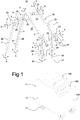
- a portable drying device for painting plants according to the invention is indicated as a whole with the number 10.
- This device 10 comprises a load-bearing structure 11 with which there is associated a containment case 12 (as an example, of the box-shaped type) for a blower 13.
- the blower 13 is a side channel blower.
- the blower 13 is fixed to the base of the load-bearing structure 11 by means of vibration damping supports 14.
- the air inlet 15 of the blower 13 is produced on a side 12A of the case 12.
- control panel 16A On the front 12B of the case 12 there is provided a control panel 16A and a handle 16B.
- the air inlet 15 is connected to the blower 13 by means of a first duct 18.
- the drying device 10 further comprises a pair of articulated arms 19, inside which there are provided respective pipes 20 that connect the inlet of the blower 13 with respective nozzles 21 for ejecting the drying air toward the area to be dried.
- Each arm 19 is formed by a plurality of tubes 22, in this example with a rectilinear axis, connected to one another by internally hollow sealed hinges 23, of the type with a single rotation axis X (to rotate according to the arrow f).
- Each hinge 23 has two sleeve portions 24, coupled to respective ends of respective tubes 22, and hinged to one another according to the rotation axis X.
- the hinge 23 is of friction type, and therefore allows stiffening of the rigidity of the hinge, preventing its rotation around X, thus allowing the arm to be self-supporting. Regulation of the rigidity of the hinge, i.e., of the friction, takes place by means of rotation of the knob 25.
- the ends of the tubes 22 are constrained in a sealed manner to the respective sleeve portions 24 by means of a rotational constraint, and therefore can rotate (according to the arrow k) on the respective sleeve portions around the axes Y of extension of the tubes 22, i.e., axes orthogonal to the axis X of the hinge 23 to which they are connected.
- the arms 19 can assume a varied configuration of extension, so that the nozzles can be positioned in the most advantageous manner on the part to be dried.
- Each arm 19 comprises an initial tube 22', hinged at the load-bearing structure and adapted to rotate around the axis of extension of this tube, in this example a vertical axis Z (to rotate according to the arrow w).
- the initial tube 22' is hinged vertically to a structural duct 27 integral with the case 12, connected to the inlet of the blower 13 by means of sections inlet duct 28A and 28B.
- each arm 19 is in the form of an end tube 22', preferably rectilinear, with one end closed and the opposite end open and connected to a respective hinge 23 (which allows rotation of the tube around X, according to the arrow f) by means of the rotating seal 29, which allows this end tube also to rotate around its axis of extension Y (to rotate according to the arrow h).
- the blower uses air (optionally filtered by means of a filter) collected in the area of the air inlet 15.
- the suction of the inlet can be connected with an inert gas tank, so as to obtain a controlled flow of gas.
- Operation of the drying device is as follows. Imagine having to dry, for example, the front side panel and the hood of a motor vehicle.
- the drying device is placed close to the part to be dried.
- One or two arms are configured to be able to position their nozzle to dry, for example, the side panel of the vehicle, while the second arm is oriented to position the second nozzle to dry the hood.
- the device is activated via the control panel 16A, and operated for the time required.
- the drying device is movable on small wheels, can be supplied with 3-phase or single-phase power, and has inside a side channel blower.
- the device is adapted to dry and clean parts, surfaces and paints, by blowing air or inert fluid without oils and condensates, filtered by means of filtration.
- the fluid is distributed on the surface to be treated by means of nozzles with air blade openings. These air blades can be rotated through 360 degrees, and are mounted on arms that can also be oriented through 360 degrees of rotation.
- These arms are self-supporting and can be blocked in the required position by means of a friction system, and have inside a free flow pipe for transporting air (fluid).
- This device is advantageous for drying paints, liquids, condensates and galvanic treatments, reducing conventional drying times by at least four times, and with a treated surface of 2.5/3 sqm per application.
Landscapes
- Engineering & Computer Science (AREA)
- Mechanical Engineering (AREA)
- General Engineering & Computer Science (AREA)
- Drying Of Solid Materials (AREA)
Applications Claiming Priority (1)
| Application Number | Priority Date | Filing Date | Title |
|---|---|---|---|
| IT201900014694 | 2019-08-13 |
Publications (1)
| Publication Number | Publication Date |
|---|---|
| EP3779340A1 true EP3779340A1 (fr) | 2021-02-17 |
Family
ID=69106041
Family Applications (1)
| Application Number | Title | Priority Date | Filing Date |
|---|---|---|---|
| EP20190229.3A Withdrawn EP3779340A1 (fr) | 2019-08-13 | 2020-08-10 | Dispositif de séchage portable pour installations de peinture |
Country Status (1)
| Country | Link |
|---|---|
| EP (1) | EP3779340A1 (fr) |
Citations (7)
| Publication number | Priority date | Publication date | Assignee | Title |
|---|---|---|---|---|
| EP0261278A1 (fr) * | 1986-09-13 | 1988-03-30 | Tokai Chemical Industries, Ltd. | Appareil de chauffage |
| JPH0631221A (ja) * | 1992-04-30 | 1994-02-08 | Imperial Chem Ind Plc <Ici> | 塗装用囲い及びパネル表面のコーティングからの水分または他の溶剤の蒸発促進方法 |
| EP1420985A1 (fr) | 2001-08-16 | 2004-05-26 | WashTec Holding GmbH | Dispositif de sechage de vehicules |
| EP1650091A1 (fr) * | 2004-10-20 | 2006-04-26 | Tassilo Posth | Appareil de séchage à main pour véhicules automobiles nettoyés |
| EP1947409A1 (fr) * | 2007-01-22 | 2008-07-23 | Gary Richardson | Séchoirs |
| DE102008058557A1 (de) * | 2008-11-20 | 2010-05-27 | Tassilo Posth | Handgerät zur Trocknung gewaschener Fahrzeuge |
| US20140202026A1 (en) * | 2011-07-28 | 2014-07-24 | Q Chip Ltd. | Bead collection device and method |
-
2020
- 2020-08-10 EP EP20190229.3A patent/EP3779340A1/fr not_active Withdrawn
Patent Citations (7)
| Publication number | Priority date | Publication date | Assignee | Title |
|---|---|---|---|---|
| EP0261278A1 (fr) * | 1986-09-13 | 1988-03-30 | Tokai Chemical Industries, Ltd. | Appareil de chauffage |
| JPH0631221A (ja) * | 1992-04-30 | 1994-02-08 | Imperial Chem Ind Plc <Ici> | 塗装用囲い及びパネル表面のコーティングからの水分または他の溶剤の蒸発促進方法 |
| EP1420985A1 (fr) | 2001-08-16 | 2004-05-26 | WashTec Holding GmbH | Dispositif de sechage de vehicules |
| EP1650091A1 (fr) * | 2004-10-20 | 2006-04-26 | Tassilo Posth | Appareil de séchage à main pour véhicules automobiles nettoyés |
| EP1947409A1 (fr) * | 2007-01-22 | 2008-07-23 | Gary Richardson | Séchoirs |
| DE102008058557A1 (de) * | 2008-11-20 | 2010-05-27 | Tassilo Posth | Handgerät zur Trocknung gewaschener Fahrzeuge |
| US20140202026A1 (en) * | 2011-07-28 | 2014-07-24 | Q Chip Ltd. | Bead collection device and method |
Similar Documents
| Publication | Publication Date | Title |
|---|---|---|
| EP0690279B1 (fr) | Procédure et dispositif d'accelération de séchage d'une pièce dans une cabine de peinture | |
| CN103313799A (zh) | 喷漆柜 | |
| CN110773365A (zh) | 一种机械零部件加工的多角度自动化喷漆设备 | |
| CN111632786B (zh) | 一种用于高分子材料的双面同步喷涂系统 | |
| CN106862013B (zh) | 一种用于框架过滤器涂胶的涂胶设备 | |
| CN102716831A (zh) | 一种干式喷漆室 | |
| JP5298665B2 (ja) | 筒体の塗装設備 | |
| EP3779340A1 (fr) | Dispositif de séchage portable pour installations de peinture | |
| EP1967804B1 (fr) | Dispositif et procédé de séchage pour carrosseries peintes, et dispositif de circulation d'air de séchage dans un tel dispositif et procédé | |
| CN107234030B (zh) | 喷漆岗位静压送风单元以及喷漆漆雾净化系统 | |
| CN215390340U (zh) | 一种用于喷漆房的送风系统 | |
| WO2015184324A1 (fr) | Appareils à air directionnel, systèmes et leurs procédés d'utilisation | |
| WO2006085061A1 (fr) | Systeme d'extraction localise | |
| CN108636734A (zh) | 一种汽车维修保养用红外线烤漆设备 | |
| CN220919833U (zh) | 一种汽车部件喷涂风干装置 | |
| CN113680577A (zh) | 一种公路设备用漆面防护装置 | |
| KR20160073189A (ko) | 도장용 무전원 환기장치 | |
| CN223988647U (zh) | 一种阀门喷漆装置 | |
| CN221360700U (zh) | 一种喷漆翻转架 | |
| CN112756154A (zh) | 一种智能环保喷涂机器人及其喷涂方法 | |
| EP1226392B1 (fr) | Salle a environnement de travail | |
| CN222447016U (zh) | 一种家具喷漆装置 | |
| CN220802511U (zh) | 大气污染防治喷淋设备 | |
| CN212922769U (zh) | 一种物流运输箱用的消毒装置 | |
| CN215612686U (zh) | 轿厢板喷涂装置 |
Legal Events
| Date | Code | Title | Description |
|---|---|---|---|
| PUAI | Public reference made under article 153(3) epc to a published international application that has entered the european phase |
Free format text: ORIGINAL CODE: 0009012 |
|
| STAA | Information on the status of an ep patent application or granted ep patent |
Free format text: STATUS: THE APPLICATION HAS BEEN PUBLISHED |
|
| AK | Designated contracting states |
Kind code of ref document: A1 Designated state(s): AL AT BE BG CH CY CZ DE DK EE ES FI FR GB GR HR HU IE IS IT LI LT LU LV MC MK MT NL NO PL PT RO RS SE SI SK SM TR |
|
| AX | Request for extension of the european patent |
Extension state: BA ME |
|
| STAA | Information on the status of an ep patent application or granted ep patent |
Free format text: STATUS: THE APPLICATION IS DEEMED TO BE WITHDRAWN |
|
| 18D | Application deemed to be withdrawn |
Effective date: 20210818 |