EP3779357B1 - Localisation d'un instrument d'arpentage - Google Patents
Localisation d'un instrument d'arpentage Download PDFInfo
- Publication number
- EP3779357B1 EP3779357B1 EP19191324.3A EP19191324A EP3779357B1 EP 3779357 B1 EP3779357 B1 EP 3779357B1 EP 19191324 A EP19191324 A EP 19191324A EP 3779357 B1 EP3779357 B1 EP 3779357B1
- Authority
- EP
- European Patent Office
- Prior art keywords
- point cloud
- sparse
- geometry
- environment
- surveying instrument
- Prior art date
- Legal status (The legal status is an assumption and is not a legal conclusion. Google has not performed a legal analysis and makes no representation as to the accuracy of the status listed.)
- Active
Links
Images

Classifications
-
- G—PHYSICS
- G01—MEASURING; TESTING
- G01C—MEASURING DISTANCES, LEVELS OR BEARINGS; SURVEYING; NAVIGATION; GYROSCOPIC INSTRUMENTS; PHOTOGRAMMETRY OR VIDEOGRAMMETRY
- G01C15/00—Surveying instruments or accessories not provided for in groups G01C1/00 - G01C13/00
- G01C15/002—Active optical surveying means
-
- G—PHYSICS
- G06—COMPUTING OR CALCULATING; COUNTING
- G06T—IMAGE DATA PROCESSING OR GENERATION, IN GENERAL
- G06T7/00—Image analysis
- G06T7/70—Determining position or orientation of objects or cameras
-
- G—PHYSICS
- G01—MEASURING; TESTING
- G01C—MEASURING DISTANCES, LEVELS OR BEARINGS; SURVEYING; NAVIGATION; GYROSCOPIC INSTRUMENTS; PHOTOGRAMMETRY OR VIDEOGRAMMETRY
- G01C11/00—Photogrammetry or videogrammetry, e.g. stereogrammetry; Photographic surveying
- G01C11/02—Picture taking arrangements specially adapted for photogrammetry or photographic surveying, e.g. controlling overlapping of pictures
-
- G—PHYSICS
- G01—MEASURING; TESTING
- G01S—RADIO DIRECTION-FINDING; RADIO NAVIGATION; DETERMINING DISTANCE OR VELOCITY BY USE OF RADIO WAVES; LOCATING OR PRESENCE-DETECTING BY USE OF THE REFLECTION OR RERADIATION OF RADIO WAVES; ANALOGOUS ARRANGEMENTS USING OTHER WAVES
- G01S17/00—Systems using the reflection or reradiation of electromagnetic waves other than radio waves, e.g. lidar systems
- G01S17/88—Lidar systems specially adapted for specific applications
- G01S17/89—Lidar systems specially adapted for specific applications for mapping or imaging
-
- G—PHYSICS
- G01—MEASURING; TESTING
- G01S—RADIO DIRECTION-FINDING; RADIO NAVIGATION; DETERMINING DISTANCE OR VELOCITY BY USE OF RADIO WAVES; LOCATING OR PRESENCE-DETECTING BY USE OF THE REFLECTION OR RERADIATION OF RADIO WAVES; ANALOGOUS ARRANGEMENTS USING OTHER WAVES
- G01S5/00—Position-fixing by co-ordinating two or more direction or position line determinations; Position-fixing by co-ordinating two or more distance determinations
- G01S5/16—Position-fixing by co-ordinating two or more direction or position line determinations; Position-fixing by co-ordinating two or more distance determinations using electromagnetic waves other than radio waves
-
- G—PHYSICS
- G06—COMPUTING OR CALCULATING; COUNTING
- G06T—IMAGE DATA PROCESSING OR GENERATION, IN GENERAL
- G06T7/00—Image analysis
- G06T7/30—Determination of transform parameters for the alignment of images, i.e. image registration
-
- G—PHYSICS
- G06—COMPUTING OR CALCULATING; COUNTING
- G06T—IMAGE DATA PROCESSING OR GENERATION, IN GENERAL
- G06T7/00—Image analysis
- G06T7/50—Depth or shape recovery
- G06T7/55—Depth or shape recovery from multiple images
- G06T7/579—Depth or shape recovery from multiple images from motion
-
- G—PHYSICS
- G06—COMPUTING OR CALCULATING; COUNTING
- G06T—IMAGE DATA PROCESSING OR GENERATION, IN GENERAL
- G06T7/00—Image analysis
- G06T7/60—Analysis of geometric attributes
-
- G—PHYSICS
- G06—COMPUTING OR CALCULATING; COUNTING
- G06T—IMAGE DATA PROCESSING OR GENERATION, IN GENERAL
- G06T7/00—Image analysis
- G06T7/70—Determining position or orientation of objects or cameras
- G06T7/73—Determining position or orientation of objects or cameras using feature-based methods
- G06T7/75—Determining position or orientation of objects or cameras using feature-based methods involving models
Definitions
- the invention relates to a method for localization of a movable surveying instrument according to the preamble of claim 1, which can also at least partially be embodied as a stored computer program product, and to a corresponding movable surveying instrument according to claim 12.
- Surveying instruments are also used over a long time - but often with pauses in-between when the instrument is shut down to save power - and/or are the instruments (as expensive singular resources) are often moves at the site along some random trajectories from one measurement to the next. Therefore, ambiguousness and/or drift of the localization can be quite problematic, sometimes even more problematic than the actually achievable position and/or orientation accuracy of the localization.
- the patent application EP 18 190 344 proposes a capturing of a coarse 3D-model by a surveying device with a 3D-sensor-unit which information is then used to derive the actual measurements with high accuracy by the surveying device.
- documents like e.g. DE 11 2006 003 390 , WO 2015/001063 , US 2011/238303 , EP 3 333 538 , EP 3 222 969 , EP 3 034 995 , US 2011/102255 are related to various localization approaches.
- the localization can be established with respect to a real world, on the site reference coordinate system, which is preferably not only a theoretical one, but a real world or as built coordinate system.
- a real world coordinate system can often deviate from the planed one, be it as a result of tolerances, mistakes, aging, etc. or simply as the environment itself changes, e.g. as dimensions of a building changed due to adaptions or application of new cladding or insulation, by attachments of additional constructions, by unplanned items or vegetation at the site, etc.
- the present invention relates to a method for surveying an environment and/or deriving and providing a localization of a movable surveying instrument with respect to its environment.
- the method is preferably executed during carrying or movement of the instrument and maybe immediately after until a static result is found.
- the surveying instrument is therein movable in its environment along a substantially random trajectory and configured to be carried by a human, preferably configured to be hand-carried e.g. by a handle or optionally configured as a shoulder bag or a backpack.
- the surveying instrument is therein a geodetic instrument configured as a Laser-Scanner, a Theodolite, a GNSS-Surveying antenna, a Mobile-Mapping-System, and/or a Surveying-Field-Controller.
- the surveying instrument can therein comprise a measurement unit for deriving measurement values with geodetic accuracy, e.g. in a range below centimeters.
- the movable surveying instrument is configured to be carried, which in particular means that it is a non-autonomous instrument and not configured as an autonomous vehicle like a UAV, AGV, drone, robot, rover, car or the like, which is configured with a drive unit for the movement and uses a SLAM approach for its own autonomous navigation in the environment.
- the surveying instrument according to the invention is an instrument configured and designed for the primary purpose of taking exact measurements of its environment, in particular to derive plan-data for construction work, manufacturing or the like.
- the surveying instrument is configured to derive distances and or angular measurement values which are to scale in defined real world measurement units.
- the method comprises a progressional capturing of a sparse evolving point cloud of at least part of the environment of the surveying instrument and a progressional deriving of a trajectory of movement of the surveying instrument position with respect to the sparse evolving point cloud.
- the capturing of the sparse evolving point cloud comprises a progressional capturing of 2D-images by at least one camera at the surveying instrument and applying a visual simultaneous location and mapping algorithm (VSLAM) based on the progressional series of camera images during the movement of the instrument.
- VSLAM visual simultaneous location and mapping algorithm
- the VSLAM can also be implemented as a visual inertial simultaneous location and mapping algorithm (VISLAM) with also takes into account measurement values of inertial sensors such as accelerometers, gyroscopes or the like for the deriving of the sparse evolving point cloud.
- the point cloud is sparse, which means that not for every image-pixel a depth value is derived, and it is evolving, which means that it is not a static snapshot, but the SLAM algorithm continuously tries to derive points for the point cloud, in particular upon a change or addition of an image.
- the method according to the invention comprises a progressional matching of the sparse evolving point cloud with a known CAD-geometry, like a known theoretical plan- or CAD-information of at least part of the environment, and a progressional determining and providing of a spatial localization and orientation of the surveying instrument in relation to the known plan- or CAD-information according to the matching.
- the matching is done with a minimizing of a mathematical functional, which is configured to model or reflect distances between the points of the sparse point cloud and the known CAD-geometry.
- a functional can e.g. comprise at least a parameter of a pose and/or a parameter of a position of points in the sparse point cloud.
- a spatial measurement unit of the surveying instrument Upon deriving of at least one exact surveying measurement value of the environment by a spatial measurement unit of the surveying instrument, a combining of this exact measurement with the sparse point cloud and/or the plan information can be established, in particular with a referencing and/or aligning the surveying measurement value to the known CAD-geometry according to the spatial localization and orientation.
- the spatial measurement unit is therein in particular a separate, additional unit besides and independent of the SLAM evaluation of the camera images.
- a sparse point cloud is a point cloud, in which not for all (or not for substantially all) of the recorded pixels, a depth value is evaluated, such that a 3D-voxel is derived.
- a depth value is determined, e.g. for less than half of the pixels or preferably for about 20% to 10% of the pixels or even less.
- such a sparse point cloud can comprise some tens to a few hundred voxels, in an embodiment e.g. resulting in a point density in a range of about 0.5-2 pts/m 2 or the like.
- Progressional can herein be described as a consecutively or continuously processing on evolving or changing, not fully static data at runtime.
- Evolving means that the point cloud is not a static single shot, like a singular capturing of a laser-scanner that is later on post-processed, but an ever changing continuously updated point cloud fed by an algorithm that continuously tries to extract points. Accordingly, also the matching and solving of the optimization problem according to the invention is done progressional or constantly, which can in particular mean periodically with a high update rate, preferably at least whenever the point cloud evolves.
- the progressional matching according to the invention can therein be done with a solving of an optimization problem.
- a progressional adapting of a scaling and/or orientation of the floorplan and/or of the known theoretical plan- or CAD-information is optimized to find an optimal correspondence or to minimize a geometrical error term of the matching.
- the method can comprise a continuous or progressional identifying or finding of correspondences of the sparse point cloud and the known CAD-geometry and/or an updating of those correspondences according to the minimizing of the functional, in particular comprising an executing of an iterative closest point (ICP) optimization algorithm.
- ICP iterative closest point
- a correspondence of planes, normal, lines, edges, corners and or dimensions can be continuously optimized in a 2D or 3D space.
- Such an optimizing can e.g. comprise an iterative closest point (ICP) optimization algorithm, a least square fit or another optimization algorithm, in particular with a minimizing of distances in-between points of the point cloud and the known CAD-geometry and automatically finding correspondences and optimizing distances, preferably with a minimizing of closest point-to-plane distances.
- the minimizing of the functional and the identifying and/or updating of correspondences can therein be executed iteratively in a process of an optimization routine, e.g. in a progressional loop while optimizing a cost-function that can comprise an error term of the matching, preferably cost function rated for certain classes of points in the point cloud that are classified by a classification algorithm of an artificial intelligence system, e.g. being classified to be planes, lines, horizontal, vertical, or other geometries, or even one of certain known objects.
- the optimization problem can in particular be configured in such a way, that a drift in the sparse evolving point cloud is compensated for, e.g. with a progressive, dynamical adapting of an absolute relation of the sparse evolving point cloud and the known theoretical plan- or CAD-information and/or by an applying of a deformable theoretical plan- or CAD-information in the matching.
- the deriving of the sparse evolving point cloud is done by an according 3D sensor unit that is configured to derive at least a sparse, (optionally also a dense) point cloud of the environment, which is continuously evolving over time. This means not taking a single static snapshot of the environment but a continuous ever changing and/or supplementing point cloud that evolves over time and/or movement of the surveying device.
- the 3D-sensor-unit can therein in particular be embodied as a RIM camera sensor, a stereo imaging sensor, a structured light sensor, a triangulation sensor, a structure from motion sensor, a simultaneous location and mapping sensor, or a depth image sensor.
- the progressive deriving of the sparse evolving point cloud can e.g. be established by a visual simultaneous localization and mapping (VSLAM) unit.
- VSLAM can comprise a progressional capturing of a series of images from at least one camera at the surveying instrument, which can be a 2D-visual-camera.
- a VSLAM algorithm continuously, preferably substantially in real time or progressively during runtime, derives a dynamically adapting, sparse evolving point cloud of the environment. This is in particular be done during a moving of the surveying instrument along any random trajectory in the environment.
- the VSLAM algorithm can therein comprise a tracking and triangulating of identified visual features and/or landmarks in a plurality of those images of the series of images. Based thereon, a deriving of at least three dimensional coordinates of the visual features and/or landmarks can be established, which coordinates can form points in the sparse evolving point cloud.
- the present invention can use 3D-sensor-unit embodied by a visual inertial SLAM unit, which comprises one or more visual cameras as well as an inertial sensor, e.g. an IMU-unit providing data in 6 degrees of freedom, optionally also equipped with an electronic compass module.
- a visual inertial SLAM unit which comprises one or more visual cameras as well as an inertial sensor, e.g. an IMU-unit providing data in 6 degrees of freedom, optionally also equipped with an electronic compass module.
- Such a visual inertial SLAM (simultaneous localization and mapping) system can be based on triangulated, 3D point clouds (or maps), which are created out of visually tracked features in a series of camera images.
- These point clouds are maintained and updated all the time while the system is in operation, when stationed as well as when moved around at the site.
- the progressional matching can be done with a synchronizing of the sparse evolving point cloud and the known theoretical plan- or CAD-information in at least three dimensions.
- the synchronizing can therein be embodied as a direct synchronizing of three dimensional points in the sparse evolving point cloud with points in the theoretical plan- or CAD-information and/or it can be embodied with an implicit synchronizing of correspondences of those points, for example comprising a RANSAC (random sample consensus) optimization algorithm.
- the optimizing can be established with the theoretical plan- or CAD-information as auxiliary condition to the optimization problem.
- the matcher algorithm can be optimizing a rotation and/or scaling of the CAD layout, until an optimal solution for the matching is found. Once this is fulfilled, the sparse evolving point cloud and thereby the actual pose of the surveying instrument is known with respect to the CAD design data, which can then be used as a basic spatial reference location for the measurement tasks to be executed by the surveying instrument.
- the progressional matching can also be embodied to comprise a progressional deriving of a 2D-floorplan or a layout of the environment by a substantially vertical projecting of points of the sparse evolving point cloud to a substantially horizontal plane.
- a projecting can in particular comprise those of the points, which are arranged in non-equal horizontal planes and/or with a deriving of a density of the projected points in the plane, which has to be above a static or dynamically adapted limit in order to define a point in the 2D-floorplan.
- a classifying of the points according to their planar accumulation in the projecting can be established.
- Such a floor layout extracting from this point cloud can for example be embodied with a projecting of all points to the ground plane.
- a density of the projected points in the ground plane can then be evaluated as an indication for a presence of a vertical structure, like a wall or the like.
- the thereof resulting floor layout is then matched to known data, as e.g. a CAD site or a CAD floor plan.
- this matching is done with a solving of an optimization problem.
- This matching is therein done progressional or continuously, for example during movement of the instrument, during measurement, during measurement pauses, etc., preferably substantially the whole time the measurement instrument is in the field to be used.
- the present invention can not only overcome drawbacks because of a noisy and sparse SLAM layout.
- the present invention can therein also take into account that CAD plan might be outdated, may be a theoretical one that comprises dimensions as planned but not necessarily as built, or may not contain all real life objects, like trees, transient objects, furnishing, annexes, construction materials lying around, etc. All those aspects cause mismatches and/or ambiguities.
- An embodiment of the invention can also comprise an automatic discerning or identifying of objects in the sparse evolving point cloud and/or in 2D-images of the environment.
- Such can comprise an identification unit, which can at least partially be configured by machine learning, for automatically identifying objects which are absent in the known plan- or CAD-information on basis of the sparse evolving point cloud and/or on basis of visual 2D-images of the environment.
- the automatic identifying can also relate to an automatic identifying of dimensional deviations in the sparse evolving point cloud compared to the known plan- or CAD-information.
- this can also comprise an automatic classifying of the identified objects or deviations by a machine learned classifier. Such identification and/or classification can then - together with the localization information - be reported to a BIM system and/or to an operator of the surveying instrument.
- the present invention can therein also comprise a supplementing and/or updating of the known theoretical plan- or CAD-information of the environment according to the identified objects and/or deviations. For example, with an online updating of the known theoretical plan- or CAD-information of the environment in an online BIM-database, on a storage media or on a cloud storage.
- an example of a specific embodiment of the present invention can be described to concern an automated localization system for a surveying instrument at a worksite environment. From a system and flexibility perspective, it might be an option to consider a visual inertial SLAM system, but such known to be bound to drift, wherefore such a localization approach on a site tends to be error prone and unreliable.
- the present invention proposes a CAD-SLAM matching that is not executed one single time only but executed periodically or preferably substantially or quasi continuously, constantly or progressional on site, in particular during movement of the instrument or the instruments camera - since then the SLAM system can provide updates to the point cloud. By this progressional matching, the present invention can correct for drifts of the visual odometry system and can provide a robust and stable localization of the instrument.
- Such an embodiment also allows to run the matching algorithm when only a small subset of the site has been seen by the SLAM system.
- the matching is executed periodically or preferably continuously to ensure that any drift of the SLAM system is minimized in its impact to the localization.
- Another aspect is a utilization of a deformable CAD layout model in the matching, which can be used to improve the matching when the SLAM system drifts.
- differences can be detected between the CAD model and the SLAM point cloud. For example, such differences can on the one hand improve the robustness of SLAM and/or on the other hand can be used for quality assurance for the architect or for a BIM information management system.
- the present invention also relates to an according surveying instrument that is configured with a unit for carrying out the method described above, for example such as a Total-Station (TPS), a GNSS surveying system, a laser Scanner (TLS), a handheld laser distance meter, a surveying field controller, etc. or a combination of those that can be operated together for establishing a surveying task.
- a unit can e.g. comprise a computation unit and can also use data from various sensors which are already present at the instrument for other purposes, such as e.g. cameras, tilt sensors, IMUs, laser distance meters, etc.
- An embodiment of a movable surveying instrument according to the invention is configured with
- the sparse evolving point cloud can therein preferably be derived by a visual simultaneous localization and mapping (VSLAM) unit, which is configured in such a way that, bases on the series of images from the at least one camera at the surveying instrument, the dynamically adapting sparse evolving point cloud of the environment is progressively derived.
- VSLAM visual simultaneous localization and mapping
- the matching unit of the movable surveying instrument can therein comprise a solver for an optimization problem that is configured to constantly optimize a localization of the surveying instrument with respect to the known theoretical plan- or CAD-information, preferably in a position and in an orientation, by solving a mathematical optimization problem in two or three dimensions, whereby robustness to drifts and deviations of the point cloud can be established as well as an absolute reference to the plan information and/or to global coordinates.
- a solver for an optimization problem that is configured to constantly optimize a localization of the surveying instrument with respect to the known theoretical plan- or CAD-information, preferably in a position and in an orientation, by solving a mathematical optimization problem in two or three dimensions, whereby robustness to drifts and deviations of the point cloud can be established as well as an absolute reference to the plan information and/or to global coordinates.
- the invention also relates to an instrument, device or system which is configured for the method according to the invention.
- the present invention therefore also relates to a movable or mobile surveying instrument which is configured to execute a method as described herein, in particular configured to provide a localization of the device with respect to a given theoretical plan information like a CAD-model.
- a device can comprise at least a computation unit, a 3D-sensor unit to derive a sparse point cloud of its environment and access to a storage for the theoretical plan information, e.g. at a local or online storage media.
- the device can comprise a Simultaneous Localization and Mapping (SLAM) unit as 3D-sensor unit, configured for constructing or updating a map of an unknown environment while simultaneously keeping track of the device's location within it, which can be utilized in the deriving of the location information for the field of view of the camera image, in particular visual SLAM (VSLAM) that is evaluating the images from the camera.
- SLAM Simultaneous Localization and Mapping
- An embodiment of the invention also relates to an according system providing the method, e.g. embodied as a computation unit.
- a device or system according to the present invention can comprise microcontrollers, microcomputers, DSPs or a programmable or hardwired digital logics, etc., wherefore the present invention can involve or be embodied as a computer program product with program code being stored on a machine readable medium or embodied as an electromagnetic wave (such as e.g. a wired or wireless data signal), which implements functionality according to the invention at least partially in software - which therefore is also an embodiment of the invention.
- the computer program product can in particular comprise program code being configured for a continuously deriving or reading a sparse evolving point cloud of an environment, and for a reading a known theoretical plan- or CAD-information of the environment.
- the program code is then configured for a continuously matching of the sparse evolving point cloud with the known theoretical plan- or CAD-information, which is preferably done by solving a mathematical optimization problem, configured to be robust against drifts in the point cloud and deviations in-between the data to be matched by finding an optimized solution.
- the matching therein comprises a solving of an optimization problem, e.g. with a consecutively minimizing of a functional which is configured to model a distance between the sparse evolving point cloud and the known CAD-geometry.
- the deriving of point cloud data and matching is therein done not only once, but continuously.
- the point cloud is a live evolving point cloud of the environment
- the matching is done at least once per evolution of the point cloud.
- the solving of the optimization problem is done continuously with a continuously refining the localization of the instrument as a matching result.
- the program code is deriving a localization in the environment with respect to the known theoretical plan- or CAD-information, which localization is provided to the surveying instrument and/or to a BIM system.
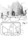
- Fig. 1 schematically shows a possible example of an embodiment of an application of a method for localization of a movable surveying instrument with respect to its environment according to the invention.
- GNSS Global System for Mobile Communications
- the surveying instrument is therein a geodetic surveying instrument which is specifically configured for a geodetic surveying task comprising dimensional measurements, for example such as a Total-Station (TPS), a GNSS surveying system, a laser Scanner (TLS), a handheld laser distance meter, a surveying field controller, etc. or a combination of those that can be operated together for establishing a surveying task.
- dimensional measurements for example such as a Total-Station (TPS), a GNSS surveying system, a laser Scanner (TLS), a handheld laser distance meter, a surveying field controller, etc. or a combination of those that can be operated together for establishing a surveying task.
- TPS Total-Station
- TLS laser Scanner
- handheld laser distance meter a handheld laser distance meter
- a surveying field controller etc.
- the surveying instrument is therein movable or mobile, which means it is configured to be moved around at a site to different locations - optionally
- instruments 10a,10b,10c there are three embodiments of instruments 10a,10b,10c illustrated, but present invention is executed individually at each of the instruments.
- the instruments are moved around the site, which is indicated by the corresponding trajectories 2a,2b,2c.
- the dots at the trajectories are indicating stops in the movements.
- the visual inertial SLAM (simultaneous localization and mapping) systems can therein be based on triangulated, 3D point clouds (maps) which are created out of visually tracked features. These point clouds are sparse or semi-dense point clouds and are maintained and updated all the time while the system is in use. Such a SLAM point cloud 1 is shown as an example.
- the corresponding theoretical plan data 3 is shown as an example on a BIM device 1, with the localizations 4 of the surveying instruments marked.
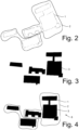
- a sparse point cloud 1 and an instrument trajectory 2 wherein the point cloud can e.g. be derived by Structure from Motion (SfM) based on a series of camera images taken during the moving of the instrument along the trajectory, for example as described for one of the surveying instruments above.
- SfM Structure from Motion
- the point cloud is shown in a floorplan view to achieve better visualization.
- the point cloud can also be a 3D point cloud and the further described matching is done in 3D space as described in Fig. 1 .
- the here and in the following described matching and optimizing can also be done as shown here in 2D space, which can simplify the evaluation and require less computational resources and energy as a matching and optimizing in full 3D space.
- such can also comprise a reduction or projection of the point cloud which is captured in 3D into a 2D floorplan.
- floor level can be defined, e.g. identifying a ground plane in the point cloud and/or by inertial sensors and to use this floor level as height reference - e.g. resulting a 2.5 dimensional localization reference.
- Fig. 3 shows an example of a theoretical building layout or plan information for the site shown above.
- Such information can be received from a BIM database, from geodetic information servers, from CAD models, digitized maps or plans or the like.
- the plan is therein theoretical, and it will most likely not match the real world or the point cloud - even if the point cloud would have an infinite precision.
- Fig. 4 an example of an embodiment of the present invention is shown, in which the building layout out of CAD model from Fig. 3 is matched with the corresponding point cloud shown in Fig. 2 .
- the matcher algorithm optimizes the rotation and scaling of the theoretical plan information, until an optimal solution is found.
- the sparse point cloud and thereby the actual pose of the instrument is known with respect to the plan information - the instrument is thereby localized and this information can be provided for further processing, e.g. as a basic rough reference for an automatic target finding unit (ATR) or the like.
- ATR automatic target finding unit
- a CAD-to-slam SLAM matching is executed periodically, preferably quasi-continuously or continuously Such can in particular provide a correcting for drifts of the localization when a visual odometry system is used to derive the sparse point cloud, especially for a point cloud that is continuously evolving over time.
- the matching with solving an optimization problem according to the invention also enables to run the matching algorithm successfully, when only a small subset of the site has been seen by the SLAM system and the point cloud is very sparse and/or only covers fractions of the environment.
- a deformable CAD layout model can be used in the optimization problem of the matching to improve the matching when the SLAM system drifts.
- the theoretical plan information or CAD-data is considered to be deformable in its dimensions and those dimensions are adapted by the optimization problem to result in a match.
- the deforming is therein done with constraints in proportionality and/or according to perspective considerations.
- the present invention can also comprise a detecting of differences between the theoretical plan information or CAD model and the sparse point cloud, preferably during the solution of the optimization problem. Such can bring improvements in the robustness of the localization in the point cloud and/or such differences can also be provided as information quality assurance, e.g. for the architect or for a BIM system.
- the differences can be geometrical differences, which can be derived in the matching.
- Another approach according to the present invention can also automatically identify and/or classify differences such as objects or obstacles obstructing the theoretical information of the plan data, which can be done in the point cloud, in the images taken by the odometry system or preferably in a combination of those. For example, by identifying furniture or a car or a tree in front of a building, the present invention can configure the matching to omit those obstructed areas of a building in the optimization problem - which will result in more optimized results with a lower error coefficient and better accuracy of the localization.
- those identified objects or items can be provided to be included into a BIM database or just omitted for the matching.
- Fig. 5 shows an example of a simplified flow diagram of an embodiment of the present invention.
- Box 51 symbolizes a solving of an optimization problem in a matching algorithm that is configured for establishing a matching of the evolving point cloud and a theoretical plan information. Details have been discussed above.
- Box 52 symbolizes a providing of a localization according to the matching which is in reference to the theoretical plan information.
- This localization can then be further processed by the surveying instrument and/or a BIM system, e.g. for taking measurement with the surveying instrument according to its localization.
Landscapes
- Engineering & Computer Science (AREA)
- Physics & Mathematics (AREA)
- General Physics & Mathematics (AREA)
- Computer Vision & Pattern Recognition (AREA)
- Theoretical Computer Science (AREA)
- Radar, Positioning & Navigation (AREA)
- Remote Sensing (AREA)
- Electromagnetism (AREA)
- Geometry (AREA)
- Multimedia (AREA)
- Computer Networks & Wireless Communication (AREA)
- Length Measuring Devices By Optical Means (AREA)
Claims (15)
- Procédé d'arpentage d'un environnement par un instrument d'arpentage mobile (10) qui est configuré comme un scanner laser, un théodolite, une antenne d'arpentage GNSS, un système de cartographie mobile et/ou un contrôleur de champ d'arpentage et configuré pour être porté par un humain dans l'environnement le long d'une trajectoire sensiblement aléatoire, le procédé comprenant- une capture progressive d'images 2D par au moins une caméra au niveau de l'instrument d'arpentage (10) et une application d'un algorithme de localisation et de cartographie visuelles simultanées ou d'un algorithme de localisation et de cartographie visuelles-inertielles simultanées qui prend également en compte des valeurs de mesure de capteurs inertiels, aveccaractérisé en ce que le procédé comprend en outre :- une dérivation progressive (50) d'un nuage de points évolutif clairsemé (1) d'au moins une partie de l'environnement de l'instrument d'arpentage (10) sur la base de la série d'images 2D capturées, et- une dérivation progressive d'une trajectoire (2) de déplacement de l'instrument d'arpentage (10) par rapport au nuage de points évolutif clairsemé (1) ;- une mise en concordance progressive du nuage de points évolutif clairsemé (1) avec une géométrie CAO connue (3) d'au moins une partie de l'environnement, avec une minimisation d'un fonctionnel qui est configuré pour modéliser une distance entre le nuage de points clairsemé (1) et la géométrie CAO connue (3) ; et- une dérivation et une fourniture (52) d'une localisation spatiale (4) et d'une orientation de l'instrument d'arpentage (10) par rapport à la géométrie CAO connue (3) selon la mise en concordance.
- Procédé selon la revendication 1,
caractérisé par- la dérivation d'au moins une valeur de mesure d'arpentage exacte de l'environnement par une unité de mesure spatiale de l'instrument d'arpentage (10), et- la combinaison de la valeur de mesure d'arpentage exacte avec le nuage de points clairsemé (1) et/ou des informations de plan, en particulier avec un référencement et/ou un alignement de la valeur de mesure d'arpentage avec la géométrie CAO connue selon la localisation spatiale et l'orientation. - Procédé selon la revendication 1 ou 2,
caractérisé en ce que
le fonctionnel comprend au moins un paramètre d'une pose et/ou un paramètre d'une position de points dans le nuage de points clairsemé. - Procédé selon l'une quelconque des revendications 1 à 3,
caractérisé par
une identification progressive et/ou une mise à jour de correspondances du nuage de points clairsemé (1) et de la géométrie CAO connue (3) selon la minimisation du fonctionnel, comprenant en particulier une exécution d'un algorithme d'optimisation du point le plus proche itératif. - Procédé selon la revendication 4,
caractérisé en ce quela minimisation du fonctionnel et l'identification et/ou la mise à jour de correspondances sont exécutées itérativement dans un processus d'optimisation (51), qui est effectué dans une boucle progressive avec une optimisation d'une fonction de coût,en particulier avec une minimisation de distances entre des points du nuage de points (1) et la géométrie CAO connue (3) et la découverte automatique de correspondances et l'optimisation de distances, de préférence avec une minimisation de distances point le plus proche à plan. - Procédé selon au moins l'une des revendications 1 à 5, caractérisé en ce que
la minimisation est configurée de telle sorte qu'une dérive du nuage de points évolutif clairsemé (1) est compensée par une adaptation progressive et dynamique d'une relation absolue entre le nuage de points évolutif clairsemé (1) et la géométrie CAO connue (3) et/ou par une application d'une géométrie CAO connue déformable (3). - Procédé selon au moins l'une des revendications 1 à 6, caractérisé en ce quela dérivation du nuage de points évolutif clairsemé (1) est effectuée- par une unité de localisation et de cartographie visuelles simultanées ou- par une unité de localisation et de cartographie visuelles-inertielles simultanées,et comprend une capture progressive d'une série d'images à partir d'au moins une caméra au niveau de l'instrument d'arpentage (10) pendant un déplacement de l'instrument d'arpentage (10) le long de la trajectoire (2) aléatoire dans l'environnement, et une adaptation dynamique du nuage de points évolutif clairsemé (1) de l'environnement progressivement pendant le temps d'exécution sur la base de ces images, en particulier dans lequel la dérivation du nuage de points évolutif clairsemé (1) comprend un suivi et une triangulation de particularités visuelles identifiées et/ou de points de repère dans une pluralité de ces images de la série d'images, et, sur cette base, la dérivation de coordonnées au moins tridimensionnelles des particularités visuelles et/ou des points de repère qui forment des points dans le nuage de points évolutif clairsemé (1).
- Procédé selon au moins l'une des revendications 1 à 7, caractérisé en ce que
la mise en concordance progressive est effectuée avec une synchronisation du nuage de points évolutif clairsemé (1) et de la géométrie CAO connue (3) dans au moins trois dimensions, en particulier dans lequel la synchronisation est une synchronisation directe de points tridimensionnels dans le nuage de points évolutif clairsemé (1) avec des points de la géométrie CAO connue (3) et/ou une synchronisation implicite de correspondances de ces points, comprenant de préférence un algorithme d'optimisation de type RANSAC. - Procédé selon au moins l'une des revendications 1 à 8, caractérisé en ce quela mise en concordance progressive comprend une dérivation progressive d'un plan de masse 2D par une projection sensiblement verticale de points du nuage de points évolutif clairsemé (1) sur un plan sensiblement horizontal, en particulier des points qui sont agencés dans des plans horizontaux non égaux, de préférence avec une classification des points selon leur accumulation planaire dans la projection,avec la mise en concordance progressive du plan de masse 2D avec la géométrie CAO connue (3) de l'environnement par la résolution d'un problème d'optimisation dans un espace bidimensionnel pour dériver une localisation 2D, en particulier avec une évaluation d'un plan sensiblement horizontal dans le nuage de points évolutif clairsemé (1) et la définition du plan sensiblement horizontal comme une référence de hauteur verticale pour la localisation 2D.
- Procédé selon au moins l'une des revendications 1 à 9, caractérisé par
une identification automatique d'objets dans le nuage de points évolutif clairsemé (1) et/ou dans des images 2D de l'environnement, en particulier avec une classification automatique de l'objet par un classificateur à apprentissage automatique, lesquels objets sont absents dans la géométrie CAO connue et/ou une identification automatique d'écarts de dimensions dans le nuage de points évolutif clairsemé (1) par rapport à la géométrie CAO connue (3). - Procédé selon la revendication 10,
caractérisé par
un complément et/ou une mise à jour de la géométrie CAO connue (3) de l'environnement selon les objets et/ou les écarts identifiés, en particulier avec une mise à jour en ligne de la géométrie CAO connue de l'environnement dans une base de données MDB en ligne. - Instrument d'arpentage mobile (10) qui est configuré comme un scanner laser, un théodolite, une antenne d'arpentage GNSS, un système de cartographie mobile et/ou un contrôleur de champ d'arpentage, et configuré pour être porté par un humain dans un environnement le long d'une trajectoire (2) sensiblement aléatoire, avec- au moins une caméra visuelle configurée pour capturer en permanence une série d'images d'un environnement,- une unité d'évaluation de nuages de points 3D configurée pour dériver en permanence un nuage de points évolutif au moins clairsemé (1) de l'environnement sur la base de la série d'images avec une unité de localisation et de cartographie visuelles simultanées ou par une unité de localisation et de cartographie visuelles-inertielles simultanées qui est configurée pour prendre également en compte des valeurs de mesure de capteurs inertiels,caractérisé en ce que l'instrument d'arpentage mobile comprend en outre :- une unité d'accès à des informations de plan, configurée pour accéder à une géométrie CAO connue (3) d'au moins une partie de l'environnement,- une unité de mise en concordance configurée pour mettre en concordance en permanence le nuage de points évolutif clairsemé (1) et la géométrie CAO connue (3) avec une minimisation d'un fonctionnel qui est configuré pour modéliser une distance entre le nuage de points clairsemé (1) et la géométrie CAO connue (3), et- une unité de localisation configurée pour dériver en continu et fournir une localisation (4) et/ou une orientation de l'instrument d'arpentage (10) dans l'environnement par rapport à la géométrie CAO connue (3) sur la base d'un résultat de l'unité de mise en concordance.
- Instrument d'arpentage mobile (10) selon la revendication 12,
caractérisé en ce que
l'unité de mise en concordance comprend une unité de résolution configurée pour un problème d'optimisation, laquelle unité de résolution est configurée pour optimiser en permanence une localisation (4) de l'instrument topographique (10) par rapport à la géométrie CAO connue (3), de préférence dans une position et dans une orientation, par la résolution d'un problème d'optimisation mathématique en deux ou trois dimensions. - Instrument d'arpentage mobile (10) selon l'une quelconque des revendications 12 ou 13,
caractérisé en ce que- le nuage de points évolutif clairsemé (1) est dérivé par une unité de localisation et de cartographie visuelles simultanées ou par une unité de localisation et de cartographie visuelles-inertielles simultanées, qui est configurée de telle sorte que l'adaptation dynamique du nuage de points évolutif clairsemé (1) de l'environnement est progressivement dérivé sur la base de la série d'images de l'au moins une caméra au niveau de l'instrument d'arpentage (10), et- une unité de mesure spatiale de l'instrument d'arpentage (10) est configurée pour fournir ses mesures référencées par rapport à la localisation (4) et/ou à l'orientation de l'instrument d'arpentage (10), de préférence avec une mise à jour du nuage de points clairsemé (1) et/ou de la géométrie CAO (3) par les mesures. - Support de stockage lisible par ordinateur comprenant des instructions qui, lorsqu'elles sont exécutées par une unité de traitement de l'instrument d'arpentage (10) selon l'une quelconque des revendications 12 à 14, amènent l'unité de traitement à réaliser les étapes du procédé de l'une quelconque des revendications 1 à 11.
Priority Applications (3)
| Application Number | Priority Date | Filing Date | Title |
|---|---|---|---|
| EP19191324.3A EP3779357B1 (fr) | 2019-08-12 | 2019-08-12 | Localisation d'un instrument d'arpentage |
| US16/991,890 US11568559B2 (en) | 2019-08-12 | 2020-08-12 | Localization of a surveying instrument |
| US18/087,664 US12462424B2 (en) | 2019-08-12 | 2022-12-22 | Localization of a surveying instrument |
Applications Claiming Priority (1)
| Application Number | Priority Date | Filing Date | Title |
|---|---|---|---|
| EP19191324.3A EP3779357B1 (fr) | 2019-08-12 | 2019-08-12 | Localisation d'un instrument d'arpentage |
Publications (2)
| Publication Number | Publication Date |
|---|---|
| EP3779357A1 EP3779357A1 (fr) | 2021-02-17 |
| EP3779357B1 true EP3779357B1 (fr) | 2024-10-23 |
Family
ID=67614519
Family Applications (1)
| Application Number | Title | Priority Date | Filing Date |
|---|---|---|---|
| EP19191324.3A Active EP3779357B1 (fr) | 2019-08-12 | 2019-08-12 | Localisation d'un instrument d'arpentage |
Country Status (2)
| Country | Link |
|---|---|
| US (1) | US11568559B2 (fr) |
| EP (1) | EP3779357B1 (fr) |
Families Citing this family (20)
| Publication number | Priority date | Publication date | Assignee | Title |
|---|---|---|---|---|
| US12462424B2 (en) * | 2019-08-12 | 2025-11-04 | Leica Geosystems Ag | Localization of a surveying instrument |
| US11145129B2 (en) * | 2019-11-13 | 2021-10-12 | International Business Machines Corporation | Automatic generation of content for autonomic augmented reality applications |
| US11748954B2 (en) | 2020-06-01 | 2023-09-05 | Snap Inc. | Tracking an augmented reality device |
| US11276201B1 (en) | 2020-06-01 | 2022-03-15 | Snap Inc. | Localizing an augmented reality device |
| US11514648B2 (en) * | 2020-12-23 | 2022-11-29 | Microsoft Technology Licensing, Llc | Aligning input image data with model input data to generate image annotations |
| WO2022256976A1 (fr) * | 2021-06-07 | 2022-12-15 | 深圳市大疆创新科技有限公司 | Procédé et système de construction de données de valeur de vérité en nuage de points dense et dispositif électronique |
| CN113379824B (zh) * | 2021-06-10 | 2022-04-01 | 浙江大学 | 一种基于双视角点云配准的类圆形水果纵横径测量方法 |
| US11900550B2 (en) | 2021-09-30 | 2024-02-13 | Snap Inc. | AR odometry using sensor data from a personal vehicle |
| CN114266867A (zh) * | 2021-12-09 | 2022-04-01 | 纵目科技(上海)股份有限公司 | 图层的构建方法、系统、终端及计算机可读存储介质 |
| US12505618B2 (en) * | 2022-02-02 | 2025-12-23 | Tencent America LLC | Manhattan layout estimation using geometric and semantic information |
| EP4312000B1 (fr) | 2022-07-29 | 2025-11-05 | Leica Geosystems AG | Mise en place automatique d'un instrument de relevé géodésique en fonction d'une base de données de marqueurs de référence |
| EP4311999B1 (fr) | 2022-07-29 | 2026-01-21 | Leica Geosystems AG | Mise en place précise, sans référence et automatique d'un instrument de relevé géodésique en fonction d'informations environnementales |
| EP4361558A1 (fr) * | 2022-10-24 | 2024-05-01 | Leica Geosystems AG | Étalonnage assisté par nuage de points d'un instrument de relevé géodésique combiné |
| EP4394316A1 (fr) * | 2022-12-31 | 2024-07-03 | Hilti Aktiengesellschaft | Procédé et système d'évaluation d'une pose pour un instrument laser |
| EP4394315A1 (fr) * | 2022-12-31 | 2024-07-03 | Hilti Aktiengesellschaft | Procédé et système de mise à jour d'une pose pour un instrument laser |
| EP4394313A1 (fr) * | 2022-12-31 | 2024-07-03 | Hilti Aktiengesellschaft | Procédé et système de mise à jour d'une pose pour un instrument laser |
| EP4394314A1 (fr) * | 2022-12-31 | 2024-07-03 | Hilti Aktiengesellschaft | Procédé et système d'évaluation d'une pose pour un instrument laser |
| EP4411499B1 (fr) | 2023-02-06 | 2025-08-27 | Hexagon Technology Center GmbH | Procédé et système de génération de données de balayage d'une zone d'intérêt |
| CN116399310B (zh) * | 2023-04-12 | 2026-02-17 | 上海华测导航技术股份有限公司 | 放样方法、装置、设备及存储介质 |
| EP4571246A1 (fr) * | 2023-12-13 | 2025-06-18 | Hexagon Technology Center GmbH | Procédé et système de documentation d'inspection de site de construction |
Family Cites Families (9)
| Publication number | Priority date | Publication date | Assignee | Title |
|---|---|---|---|---|
| US7541974B2 (en) | 2005-12-15 | 2009-06-02 | Trimble Navigation Limited | Managed traverse system and method to acquire accurate survey data in absence of precise GPS data |
| CN101970985B (zh) * | 2008-02-29 | 2013-06-12 | 特林布尔公司 | 确定觇标相对于带有至少两台相机的测量仪的坐标 |
| EP2821750A1 (fr) | 2013-07-04 | 2015-01-07 | Hexagon Technology Center GmbH | Procédé de détermination de position pour un appareil de mesure et appareil de mesure correspondant |
| EP3034995B1 (fr) | 2014-12-19 | 2024-02-28 | Leica Geosystems AG | Procédé de détermination d'un décalage d'orientation ou de position d'un appareil de mesure géodésique et appareil de mesure correspondant |
| EP3222969B1 (fr) | 2016-03-22 | 2018-09-26 | Hexagon Technology Center GmbH | Référencement de sites de construction |
| EP3333538B1 (fr) * | 2016-12-07 | 2020-09-09 | Hexagon Technology Center GmbH | Scanner vis |
| EP3656138A4 (fr) * | 2017-07-17 | 2021-05-12 | Kaarta, Inc. | Alignement de données de signal mesurées avec des données de localisation slam et utilisations associées |
| JP7039388B2 (ja) * | 2018-05-24 | 2022-03-22 | 株式会社トプコン | 測量装置 |
| EP3614101B1 (fr) | 2018-08-22 | 2021-03-31 | Leica Geosystems AG | Référencement de tâches de construction |
-
2019
- 2019-08-12 EP EP19191324.3A patent/EP3779357B1/fr active Active
-
2020
- 2020-08-12 US US16/991,890 patent/US11568559B2/en active Active
Also Published As
| Publication number | Publication date |
|---|---|
| US11568559B2 (en) | 2023-01-31 |
| US20210049784A1 (en) | 2021-02-18 |
| EP3779357A1 (fr) | 2021-02-17 |
Similar Documents
| Publication | Publication Date | Title |
|---|---|---|
| US11568559B2 (en) | Localization of a surveying instrument | |
| Alsadik et al. | The simultaneous localization and mapping (SLAM): An overview | |
| US11714416B2 (en) | Method of navigating a vehicle and system thereof | |
| US12462424B2 (en) | Localization of a surveying instrument | |
| Yagfarov et al. | Map comparison of lidar-based 2d slam algorithms using precise ground truth | |
| US9142063B2 (en) | Positioning system utilizing enhanced perception-based localization | |
| Surmann et al. | An autonomous mobile robot with a 3D laser range finder for 3D exploration and digitalization of indoor environments | |
| US11512975B2 (en) | Method of navigating an unmanned vehicle and system thereof | |
| CN101331379B (zh) | 自身位置辨认方法和装置以及三维形状的计测方法和装置 | |
| Montemerlo et al. | Large-scale robotic 3-d mapping of urban structures | |
| US11513526B2 (en) | Method of navigating a vehicle and system thereof | |
| US20160312446A1 (en) | Method and control system for surveying and mapping a terrain while operating a bulldozer | |
| US20240192695A1 (en) | Anchoring based transformation for aligning sensor data of a robot with a site model | |
| Pang et al. | Low-cost and high-accuracy LiDAR SLAM for large outdoor scenarios | |
| CN118999577A (zh) | 位姿估计方法、装置、机器人及存储介质 | |
| Li et al. | Aerial-triangulation aided boresight calibration for a low-cost UAV-LiDAR system | |
| Axmann et al. | Maximum Consensus Localization Using an Objective Function Based on Helmert's Point Error | |
| Balula et al. | Drone-based Volume Estimation in Indoor Environments | |
| JP7338048B2 (ja) | 移動体システム | |
| Karam et al. | Microdrone-Based Indoor Mapping with Graph SLAM. Drones 2022, 6, 352 | |
| Fan | Plane extraction from inhomogeneous point clouds and plane-to-plane alignments | |
| Aouina et al. | 3d modeling with a moving tilting laser sensor for indoor environments | |
| Jonsson | Integration of ArUco Markers and QR Codes for Autonomous Drone Navigation and Positional Stability | |
| Barczyk | Invariant observer design for scan matching-aided localization: a tutorial. | |
| CN121632085A (zh) | 潜入叉式移动机器人自适应获取托盘方法和装置 |
Legal Events
| Date | Code | Title | Description |
|---|---|---|---|
| PUAI | Public reference made under article 153(3) epc to a published international application that has entered the european phase |
Free format text: ORIGINAL CODE: 0009012 |
|
| STAA | Information on the status of an ep patent application or granted ep patent |
Free format text: STATUS: THE APPLICATION HAS BEEN PUBLISHED |
|
| AK | Designated contracting states |
Kind code of ref document: A1 Designated state(s): AL AT BE BG CH CY CZ DE DK EE ES FI FR GB GR HR HU IE IS IT LI LT LU LV MC MK MT NL NO PL PT RO RS SE SI SK SM TR |
|
| AX | Request for extension of the european patent |
Extension state: BA ME |
|
| STAA | Information on the status of an ep patent application or granted ep patent |
Free format text: STATUS: REQUEST FOR EXAMINATION WAS MADE |
|
| 17P | Request for examination filed |
Effective date: 20210817 |
|
| RBV | Designated contracting states (corrected) |
Designated state(s): AL AT BE BG CH CY CZ DE DK EE ES FI FR GB GR HR HU IE IS IT LI LT LU LV MC MK MT NL NO PL PT RO RS SE SI SK SM TR |
|
| REG | Reference to a national code |
Ref country code: DE Ref legal event code: R079 Free format text: PREVIOUS MAIN CLASS: G01C0011020000 Ipc: G01C0015000000 Ref document number: 602019060717 Country of ref document: DE |
|
| GRAP | Despatch of communication of intention to grant a patent |
Free format text: ORIGINAL CODE: EPIDOSNIGR1 |
|
| STAA | Information on the status of an ep patent application or granted ep patent |
Free format text: STATUS: GRANT OF PATENT IS INTENDED |
|
| RIC1 | Information provided on ipc code assigned before grant |
Ipc: G01S 17/89 20200101ALI20240717BHEP Ipc: G01S 5/16 20060101ALI20240717BHEP Ipc: G06T 7/73 20170101ALI20240717BHEP Ipc: G06T 7/579 20170101ALI20240717BHEP Ipc: G01C 15/00 20060101AFI20240717BHEP |
|
| INTG | Intention to grant announced |
Effective date: 20240807 |
|
| GRAS | Grant fee paid |
Free format text: ORIGINAL CODE: EPIDOSNIGR3 |
|
| GRAA | (expected) grant |
Free format text: ORIGINAL CODE: 0009210 |
|
| STAA | Information on the status of an ep patent application or granted ep patent |
Free format text: STATUS: THE PATENT HAS BEEN GRANTED |
|
| AK | Designated contracting states |
Kind code of ref document: B1 Designated state(s): AL AT BE BG CH CY CZ DE DK EE ES FI FR GB GR HR HU IE IS IT LI LT LU LV MC MK MT NL NO PL PT RO RS SE SI SK SM TR |
|
| REG | Reference to a national code |
Ref country code: GB Ref legal event code: FG4D |
|
| REG | Reference to a national code |
Ref country code: CH Ref legal event code: EP |
|
| REG | Reference to a national code |
Ref country code: DE Ref legal event code: R096 Ref document number: 602019060717 Country of ref document: DE |
|
| REG | Reference to a national code |
Ref country code: IE Ref legal event code: FG4D |
|
| REG | Reference to a national code |
Ref country code: LT Ref legal event code: MG9D |
|
| REG | Reference to a national code |
Ref country code: NL Ref legal event code: MP Effective date: 20241023 |
|
| REG | Reference to a national code |
Ref country code: AT Ref legal event code: MK05 Ref document number: 1735184 Country of ref document: AT Kind code of ref document: T Effective date: 20241023 |
|
| PG25 | Lapsed in a contracting state [announced via postgrant information from national office to epo] |
Ref country code: NL Free format text: LAPSE BECAUSE OF FAILURE TO SUBMIT A TRANSLATION OF THE DESCRIPTION OR TO PAY THE FEE WITHIN THE PRESCRIBED TIME-LIMIT Effective date: 20241023 |
|
| PG25 | Lapsed in a contracting state [announced via postgrant information from national office to epo] |
Ref country code: NL Free format text: LAPSE BECAUSE OF FAILURE TO SUBMIT A TRANSLATION OF THE DESCRIPTION OR TO PAY THE FEE WITHIN THE PRESCRIBED TIME-LIMIT Effective date: 20241023 |
|
| PG25 | Lapsed in a contracting state [announced via postgrant information from national office to epo] |
Ref country code: HR Free format text: LAPSE BECAUSE OF FAILURE TO SUBMIT A TRANSLATION OF THE DESCRIPTION OR TO PAY THE FEE WITHIN THE PRESCRIBED TIME-LIMIT Effective date: 20241023 Ref country code: PT Free format text: LAPSE BECAUSE OF FAILURE TO SUBMIT A TRANSLATION OF THE DESCRIPTION OR TO PAY THE FEE WITHIN THE PRESCRIBED TIME-LIMIT Effective date: 20250224 Ref country code: IS Free format text: LAPSE BECAUSE OF FAILURE TO SUBMIT A TRANSLATION OF THE DESCRIPTION OR TO PAY THE FEE WITHIN THE PRESCRIBED TIME-LIMIT Effective date: 20250223 |
|
| PG25 | Lapsed in a contracting state [announced via postgrant information from national office to epo] |
Ref country code: FI Free format text: LAPSE BECAUSE OF FAILURE TO SUBMIT A TRANSLATION OF THE DESCRIPTION OR TO PAY THE FEE WITHIN THE PRESCRIBED TIME-LIMIT Effective date: 20241023 |
|
| PG25 | Lapsed in a contracting state [announced via postgrant information from national office to epo] |
Ref country code: BG Free format text: LAPSE BECAUSE OF FAILURE TO SUBMIT A TRANSLATION OF THE DESCRIPTION OR TO PAY THE FEE WITHIN THE PRESCRIBED TIME-LIMIT Effective date: 20241023 |
|
| PG25 | Lapsed in a contracting state [announced via postgrant information from national office to epo] |
Ref country code: ES Free format text: LAPSE BECAUSE OF FAILURE TO SUBMIT A TRANSLATION OF THE DESCRIPTION OR TO PAY THE FEE WITHIN THE PRESCRIBED TIME-LIMIT Effective date: 20241023 |
|
| PG25 | Lapsed in a contracting state [announced via postgrant information from national office to epo] |
Ref country code: NO Free format text: LAPSE BECAUSE OF FAILURE TO SUBMIT A TRANSLATION OF THE DESCRIPTION OR TO PAY THE FEE WITHIN THE PRESCRIBED TIME-LIMIT Effective date: 20250123 |
|
| PG25 | Lapsed in a contracting state [announced via postgrant information from national office to epo] |
Ref country code: GR Free format text: LAPSE BECAUSE OF FAILURE TO SUBMIT A TRANSLATION OF THE DESCRIPTION OR TO PAY THE FEE WITHIN THE PRESCRIBED TIME-LIMIT Effective date: 20250124 Ref country code: LV Free format text: LAPSE BECAUSE OF FAILURE TO SUBMIT A TRANSLATION OF THE DESCRIPTION OR TO PAY THE FEE WITHIN THE PRESCRIBED TIME-LIMIT Effective date: 20241023 Ref country code: AT Free format text: LAPSE BECAUSE OF FAILURE TO SUBMIT A TRANSLATION OF THE DESCRIPTION OR TO PAY THE FEE WITHIN THE PRESCRIBED TIME-LIMIT Effective date: 20241023 |
|
| PG25 | Lapsed in a contracting state [announced via postgrant information from national office to epo] |
Ref country code: PL Free format text: LAPSE BECAUSE OF FAILURE TO SUBMIT A TRANSLATION OF THE DESCRIPTION OR TO PAY THE FEE WITHIN THE PRESCRIBED TIME-LIMIT Effective date: 20241023 |
|
| PG25 | Lapsed in a contracting state [announced via postgrant information from national office to epo] |
Ref country code: RS Free format text: LAPSE BECAUSE OF FAILURE TO SUBMIT A TRANSLATION OF THE DESCRIPTION OR TO PAY THE FEE WITHIN THE PRESCRIBED TIME-LIMIT Effective date: 20250123 |
|
| PG25 | Lapsed in a contracting state [announced via postgrant information from national office to epo] |
Ref country code: SM Free format text: LAPSE BECAUSE OF FAILURE TO SUBMIT A TRANSLATION OF THE DESCRIPTION OR TO PAY THE FEE WITHIN THE PRESCRIBED TIME-LIMIT Effective date: 20241023 |
|
| PG25 | Lapsed in a contracting state [announced via postgrant information from national office to epo] |
Ref country code: DK Free format text: LAPSE BECAUSE OF FAILURE TO SUBMIT A TRANSLATION OF THE DESCRIPTION OR TO PAY THE FEE WITHIN THE PRESCRIBED TIME-LIMIT Effective date: 20241023 |
|
| PG25 | Lapsed in a contracting state [announced via postgrant information from national office to epo] |
Ref country code: EE Free format text: LAPSE BECAUSE OF FAILURE TO SUBMIT A TRANSLATION OF THE DESCRIPTION OR TO PAY THE FEE WITHIN THE PRESCRIBED TIME-LIMIT Effective date: 20241023 |
|
| PG25 | Lapsed in a contracting state [announced via postgrant information from national office to epo] |
Ref country code: RO Free format text: LAPSE BECAUSE OF FAILURE TO SUBMIT A TRANSLATION OF THE DESCRIPTION OR TO PAY THE FEE WITHIN THE PRESCRIBED TIME-LIMIT Effective date: 20241023 |
|
| REG | Reference to a national code |
Ref country code: DE Ref legal event code: R097 Ref document number: 602019060717 Country of ref document: DE |
|
| PG25 | Lapsed in a contracting state [announced via postgrant information from national office to epo] |
Ref country code: SK Free format text: LAPSE BECAUSE OF FAILURE TO SUBMIT A TRANSLATION OF THE DESCRIPTION OR TO PAY THE FEE WITHIN THE PRESCRIBED TIME-LIMIT Effective date: 20241023 |
|
| PG25 | Lapsed in a contracting state [announced via postgrant information from national office to epo] |
Ref country code: CZ Free format text: LAPSE BECAUSE OF FAILURE TO SUBMIT A TRANSLATION OF THE DESCRIPTION OR TO PAY THE FEE WITHIN THE PRESCRIBED TIME-LIMIT Effective date: 20241023 |
|
| PG25 | Lapsed in a contracting state [announced via postgrant information from national office to epo] |
Ref country code: IT Free format text: LAPSE BECAUSE OF FAILURE TO SUBMIT A TRANSLATION OF THE DESCRIPTION OR TO PAY THE FEE WITHIN THE PRESCRIBED TIME-LIMIT Effective date: 20241023 |
|
| PLBE | No opposition filed within time limit |
Free format text: ORIGINAL CODE: 0009261 |
|
| STAA | Information on the status of an ep patent application or granted ep patent |
Free format text: STATUS: NO OPPOSITION FILED WITHIN TIME LIMIT |
|
| PG25 | Lapsed in a contracting state [announced via postgrant information from national office to epo] |
Ref country code: SE Free format text: LAPSE BECAUSE OF FAILURE TO SUBMIT A TRANSLATION OF THE DESCRIPTION OR TO PAY THE FEE WITHIN THE PRESCRIBED TIME-LIMIT Effective date: 20241023 |
|
| 26N | No opposition filed |
Effective date: 20250724 |
|
| PGFP | Annual fee paid to national office [announced via postgrant information from national office to epo] |
Ref country code: DE Payment date: 20250820 Year of fee payment: 7 |
|
| PGFP | Annual fee paid to national office [announced via postgrant information from national office to epo] |
Ref country code: GB Payment date: 20250820 Year of fee payment: 7 |
|
| PGFP | Annual fee paid to national office [announced via postgrant information from national office to epo] |
Ref country code: FR Payment date: 20250828 Year of fee payment: 7 |
|
| PGFP | Annual fee paid to national office [announced via postgrant information from national office to epo] |
Ref country code: CH Payment date: 20250901 Year of fee payment: 7 |
|
| PG25 | Lapsed in a contracting state [announced via postgrant information from national office to epo] |
Ref country code: MC Free format text: LAPSE BECAUSE OF FAILURE TO SUBMIT A TRANSLATION OF THE DESCRIPTION OR TO PAY THE FEE WITHIN THE PRESCRIBED TIME-LIMIT Effective date: 20241023 |
|
| PG25 | Lapsed in a contracting state [announced via postgrant information from national office to epo] |
Ref country code: LU Free format text: LAPSE BECAUSE OF NON-PAYMENT OF DUE FEES Effective date: 20250812 |