EP3779906A1 - Alarme, procédé de commande et programme - Google Patents
Alarme, procédé de commande et programme Download PDFInfo
- Publication number
- EP3779906A1 EP3779906A1 EP19776460.8A EP19776460A EP3779906A1 EP 3779906 A1 EP3779906 A1 EP 3779906A1 EP 19776460 A EP19776460 A EP 19776460A EP 3779906 A1 EP3779906 A1 EP 3779906A1
- Authority
- EP
- European Patent Office
- Prior art keywords
- alert
- alarm
- control unit
- event
- fire
- Prior art date
- Legal status (The legal status is an assumption and is not a legal conclusion. Google has not performed a legal analysis and makes no representation as to the accuracy of the status listed.)
- Granted
Links
Images

Classifications
-
- G—PHYSICS
- G08—SIGNALLING
- G08B—SIGNALLING SYSTEMS, e.g. PERSONAL CALLING SYSTEMS; ORDER TELEGRAPHS; ALARM SYSTEMS
- G08B7/00—Signalling systems according to two or more of groups G08B3/00 - G08B6/00
- G08B7/06—Signalling systems according to two or more of groups G08B3/00 - G08B6/00 using electric transmission, e.g. involving audible and visible signalling through the use of sound and light sources
-
- G—PHYSICS
- G08—SIGNALLING
- G08B—SIGNALLING SYSTEMS, e.g. PERSONAL CALLING SYSTEMS; ORDER TELEGRAPHS; ALARM SYSTEMS
- G08B17/00—Fire alarms; Alarms responsive to explosion
-
- G—PHYSICS
- G08—SIGNALLING
- G08B—SIGNALLING SYSTEMS, e.g. PERSONAL CALLING SYSTEMS; ORDER TELEGRAPHS; ALARM SYSTEMS
- G08B17/00—Fire alarms; Alarms responsive to explosion
- G08B17/10—Actuation by presence of smoke or gases, e.g. automatic alarm devices for analysing flowing fluid materials by the use of optical means
-
- G—PHYSICS
- G08—SIGNALLING
- G08B—SIGNALLING SYSTEMS, e.g. PERSONAL CALLING SYSTEMS; ORDER TELEGRAPHS; ALARM SYSTEMS
- G08B7/00—Signalling systems according to two or more of groups G08B3/00 - G08B6/00
- G08B7/06—Signalling systems according to two or more of groups G08B3/00 - G08B6/00 using electric transmission, e.g. involving audible and visible signalling through the use of sound and light sources
- G08B7/062—Signalling systems according to two or more of groups G08B3/00 - G08B6/00 using electric transmission, e.g. involving audible and visible signalling through the use of sound and light sources indicating emergency exits
-
- G—PHYSICS
- G08—SIGNALLING
- G08B—SIGNALLING SYSTEMS, e.g. PERSONAL CALLING SYSTEMS; ORDER TELEGRAPHS; ALARM SYSTEMS
- G08B7/00—Signalling systems according to two or more of groups G08B3/00 - G08B6/00
- G08B7/06—Signalling systems according to two or more of groups G08B3/00 - G08B6/00 using electric transmission, e.g. involving audible and visible signalling through the use of sound and light sources
- G08B7/066—Signalling systems according to two or more of groups G08B3/00 - G08B6/00 using electric transmission, e.g. involving audible and visible signalling through the use of sound and light sources guiding along a path, e.g. evacuation path lighting strip
Definitions
- the present disclosure generally relates to alarms, control methods, and programs, and specifically, to an alarm configured to alert people to the presence of an external event such as a fire, and a method and program for controlling such an alarm.
- Patent Literature 1 discloses a known residential fire alarm.
- the residential fire alarm includes a smoke detecting unit with a smoke inlet, which is provided at the center of its cover, and detects the outbreak of a fire when the concentration of smoke produced by a fire reaches a predetermined concentration.
- the residential fire alarm further has sound holes on a lower left-hand side of the smoke detecting unit on the cover.
- a loudspeaker is arranged behind the sound holes to emit an alarm sound and a voice warning message.
- the residential fire alarm may be installed on, for example, the wall surface of a resident's room or bedroom in a dwelling house to detect, in the event of the outbreak of a fire, the fire and start sounding a fire warning.
- Patent Literature 1 JP 2010-49604 A
- examples of an event to which the residential fire alarm (alarm) should alert a resident include a variety of events (internal events) that may take place in the residential fire alarm itself in addition to a fire (an external event).
- internal events events that may take place in the residential fire alarm itself in addition to a fire (an external event).
- the resident may not be appropriately informed of the events.
- An alarm is to be installed in a structural component.
- the alarm includes an apparatus detecting unit, a control unit, and an alert unit.
- the apparatus detecting unit is configured to detect first information corresponding to an internal event relating to the alarm itself.
- the control unit is configured to receive the first information to determine a presence or absence of the internal event and is configured to receive second information relating to an external event that requires emission of an alarm sound to determine a presence or absence of the external event.
- the alert unit is configured to issue an alert concerning a presence of the internal event and a presence of the external event.
- the internal event at least includes a time for replacement of the alarm.
- the control unit is configured to cause the alert unit to issue an alert concerning the external event with priority over an alert concerning the time for replacement.
- a control method is a method for controlling an alarm installed in a structural component.
- the method includes a detecting step, a first determination step, a second determination step, and an alert step.
- the detection step includes detecting first information corresponding to an internal event relating to the alarm itself.
- the first determination step includes receiving the first information to determine a presence or absence of the internal event.
- the second determination step includes receiving second information relating to an external event that requires emission of an alarm sound to determine a presence or absence of the external event.
- the alert step includes issuing an alert concerning a presence of the internal event and a presence of the external event.
- the internal event at least includes a time for replacement of the alarm.
- the alert step includes issuing an alert concerning the external event with priority over an alert concerning the time for replacement.
- a program according to still another aspect of the present disclosure is designed to cause a computer system to carry out the control method described above.
- an alarm 1 is to be installed in a structural component C1 (i.e., a building component such as a ceiling or a wall).
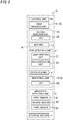
- the alarm 1 includes an apparatus detecting unit 6, a control unit 10, and an alert unit 8.
- the apparatus detecting unit 6 is configured to detect first information corresponding to an internal event relating to the alarm 1 itself.
- the control unit 10 receives the first information to determine the presence or absence of the internal event.
- the control unit 10 further receives second information relating to an external event that requires emission of an alarm sound to determine the presence or absence of the external event.
- the alert unit 8 issues an alert concerning the presence of the internal event and the presence of the external event.
- the "internal event” includes, for example, at least a time for replacement of the alarm 1.
- the internal event may include a failure in the alarm 1 and battery exhaustion in addition to the time for replacement.
- the "external event" is supposed to be, for example, a fire. Therefore, the alarm 1 may be implemented as, for example, a fire alarm that emits an alarm sound or any other type of sound at the outbreak of the fire. However, this is only an example of the present disclosure and should not be construed as limiting. Alternatively, the external event does not have to be a fire but may also be gas leakage, a tsunami, an earthquake, or intrusion of a suspicious person as long as the event requires sounding an alarm.
- the alarm 1 further includes a photoelectric sensor (as a fire detecting unit 2) for detecting smoke as a built-in component thereof.
- a photoelectric sensor as a fire detecting unit 2 for detecting smoke as a built-in component thereof.
- the fire detecting unit 2 may also be a fixed temperature sensor for detecting heat.
- the fire detecting unit 2 may also be provided as a member separate from the alarm 1.
- the control unit 10 of the alarm 1 may be provided with the second information about the fire by communicating with another alarm (a fire alarm) including the fire detecting unit 2.
- the alarm 1 may be installed on a surface (such as a ceiling surface or wall surface) of the structural component C1 such as a resident's room, a bedroom, stairs, or a hallway in a dwelling house.
- the dwelling house may be a single-family dwelling house or a multi-family dwelling house (i.e., what is called a "mansion" in Japan).
- the alarm 1 may also be installed (on the ceiling surface or wall surface) in a non-residential structural component C1, instead of the dwelling houses.
- non-dwelling structural components examples include office buildings, theaters, movie theaters, public halls, amusement facilities, complex facilities, restaurants, department stores, schools, hotels, inns, hospitals, nursing homes for the elderly, kindergartens, libraries, museums, art museums, underground shopping malls, railway stations, and airports.
- the control unit 10 is configured to cause the alert unit 8 to issue an alert concerning the fire with priority over an alert concerning the time for replacement of the alarm 1.
- the alert concerning the fire is issued before the alert concerning the time for replacement is issued. This reduces cases where the fire that requires emission of an alarm sound is present, but the alert concerning the time for replacement with a low emergency level is being issued, and a user can thus not be notified of the presence of the fire. Thus, reliability relating to the alert can be improved.
- the alarm 1 is, for example, a battery-type fire alarm.
- the alarm 1 may also be implemented as a fire alarm which is electrically connected to an external power supply (such as a commercial power grid) and which is operated by converting AC power (with an effective voltage of 100 V, for example) supplied from the external power supply into a direct current.
- an external power supply such as a commercial power grid
- the alarm 1 is supposed to be installed on a ceiling surface (which is an exemplary surface of the structural component C1) of a room in a resident's 100 dwelling house as shown in FIG. 3 .
- a ceiling surface which is an exemplary surface of the structural component C1
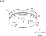
- the arrangement and operation of respective constituent elements of the alarm 1 in upward, downward, rightward, and leftward directions will be described as being defined by the up, down, right, and left arrows shown in FIG. 1 .
- the arrows indicating these directions are just shown there as an assistant to description and are insubstantial ones. It should also be noted that these directions do not define the direction in which the alarm 1 should be used.
- the alarm 1 further includes, for example, a second emission unit 12, a battery 13, an operating unit 3, a housing 4, and a light-transmitting portion 5 (see FIG. 1 ) in addition to the control unit 10, the apparatus detecting unit 6, the alert unit 8 (a first emission unit 11 and an indicating lamp 15), and the fire detecting unit 2.
- the alarm 1 further includes a storage section 7.
- the alarm 1 is supposed to be implemented as an independently operating fire alarm with no capability of communicating with other fire alarms.
- the housing 4 houses the control unit 10, the apparatus detecting unit 6, the first emission unit 11, the second emission unit 12, the battery 13, the fire detecting unit 2, the indicating lamp 15, the storage section 7, the control unit 10, and a circuit board (not shown) on which other circuit components that form various other circuits are assembled together.
- the various other circuits include an audio circuit, a first lighting circuit, a second lighting circuit, and a power supply circuit as will be described later.
- the housing 4 is made of a synthetic resin and may be made of flame-retardant ABS resin, for example.
- the housing 4 is formed in the shape of a generally compressed cylindrical shape.
- the housing 4 includes, on the upper surface thereof, a mounting portion, with which the housing 4 is mounted on one surface (installation surface) of the structural component C1.
- the housing 4 has holes 401, which are provided through a peripheral wall 400 thereof to let smoke flow into a labyrinth inside the housing 4.
- the housing 4 includes a partition wall that partitions the interior space thereof into two, upper and lower parts.
- the labyrinth and the fire detecting unit 2 are provided in the upper, first space and the control unit 10, the first emission unit 11, the second emission unit 12, the indicating lamp 15, the circuit board, and other components are provided in the lower, second space.
- the housing 4 further has a window hole 403 which has a slit shape and which is provided through a lower wall (cover) 402 and elongated in one direction (e.g., rightward/leftward direction in FIG. 1 ).
- the window hole 403 is arranged to face the first emission unit 11 housed inside the housing 4.
- the window hole 403 is provided to let the sound, emitted from the first emission unit 11, come out of the housing 4.
- the housing 4 supports the light-transmitting portion 5 on the lower wall 402 thereof such that a lower surface of the light-transmitting portion 5 is exposed on an outer surface of the housing 4.
- the light-transmitting portion 5 is a disk member with a light-transmitting property.
- the light-transmitting portion 5 is made of a material such as an acrylic resin or glass.
- the light-transmitting portion 5 is arranged to face the second emission unit 12 housed inside the housing 4.
- the light-transmitting portion 5 lets the light, emitted from the second emission unit 12, come out of the housing 4.
- the light emitted from the second emission unit 12 will be hereinafter also referred to as "illuminating light”.
- the light emitted from the second emission unit 12 has lower intensity than illuminating light emitted from a general light fixture and is bright enough to indicate an evacuation route.
- the light-transmitting portion 5 may include a lens portion, of which the outer surface is formed in a convex shape to direct the light emitted from the second emission unit 12 toward a surrounding region R1 such as a floor surface. If necessary, a light guide member for efficiently guiding the light emitted from the second emission unit 12 toward the light-transmitting portion 5 may be provided between the light-transmitting portion 5 and the second emission unit 12.
- the housing 4 further supports, on the lower wall 402, the operating unit 3 such that the lower surface of the operating unit 3 is exposed on the outer surface of the housing 4.
- the operating unit 3 accepts an operating command entered externally.
- the operating unit 3 is configured to be pushed upward by the user with one of his or her fingers, for example.
- the operating unit 3 is a disk member with a light-transmitting property.
- the operating unit 3 is arranged to face the indicating lamp 15 housed inside the housing 4.
- the operating unit 3 is configured to press down a push button switch (not shown) housed inside the housing 4 when subjected to a push operation.
- the window hole 403 and the operating unit 3 are arranged in line in one direction (e.g., in the rightward/leftward direction in FIG. 1 ) such that the center of the lower surface of the lower wall 402 is interposed between the window hole 403 and the operating unit 3, for example. Furthermore, when the lower surface of the lower wall 402 is looked up to from under the housing 4, the light-transmitting portion 5 is located closer to the front end with respect to the center of the lower surface of the lower wall 402.
- the alert unit 8 alerts a person to the presence of internal events which are a time for replacement of the alarm 1 (hereinafter simply referred to as a "time for replacement"), and a failure in the alarm 1 (hereinafter simply referred to as a "failure”) and battery exhaustion (a state where the residual capacity of the battery 13 is small).
- the battery 13 may be a lithium-ion battery, for example.
- the alert unit 8 alerts a person to the presence of the presence of a fire which is an external event.
- both of the first emission unit 11 and the indicating lamp 15 correspond to the alert unit 8, but only one of them may correspond to the alert unit 8.
- the first emission unit 11 has a function of alerting a person to the presence of the internal events and a function of alerting a person to the presence of a fire.
- the first emission unit 11 emits a sound (i.e., an acoustic wave).
- the control unit 10 determines that a fire should be present, the first emission unit 11 emits an alarm sound to alert a person to the presence of the fire.
- the first emission unit 11 may be implemented as a loudspeaker that transduces an electrical signal into a sound.
- the loudspeaker includes a diaphragm and emits an alarm sound by mechanically vibrating the diaphragm in accordance with the electrical signal.
- the loudspeaker is formed in the shape of a circular disk in a front view.
- the first emission unit 11 emits an alarm sound (such as a beep) under the control of the control unit 10.
- the first emission unit 11 preferably emits the alarm sound, of which the loudness (i.e., the sound pressure level) is variable.
- the alarm sound may include a sweep sound that is swept from a low-frequency sound to a high-frequency sound.
- the alarm sound may be accompanied with a voice warning message such as "Fire! Fire!”
- the alarm sound is supposed to be made up of the sweep sound and the voice warning message continuous with the sweep sound.
- the audio circuit includes a low-pass filter and an amplifier, for example.
- PWM pulse width modulation
- the first emission unit 11 emits a sound to alert a person to the presence of the internal event. This sound is hereinafter also referred to as an "alert sound" to distinguish this sound from the alarm sound at the outbreak of a fire.
- the alert sound relating to the time for replacement includes a voice warning message, for example, "Beep, it is time for replacement of the alarm".
- An alert sound relating to a failure includes a voice warning message, for example, "Beep, a failure is caused in 'XX"'.
- An alert sound relating to battery exhaustion includes a voice warning message, for example, "Beep, please replace the battery”.
- the alert sound is emitted at a volume of about 60 to 70% of the volume of the alarm sound.
- the alert sound is periodically repeatedly emitted, for example, at hourly intervals until the corresponding internal event is resolved.
- the first emission unit 11 emits a message such as "Beep, please replace the battery” two or three times continuously every hour and thereafter emits a beep sound every 40 seconds until one hour elapses.
- the first emission unit 11 also emits the alarm sound and the alert sound tentatively even when subjected to an operation check test.
- the operation check test may be carried out by either pushing the operating unit 3 or pulling a pull string (not shown) extended from the housing 4.
- the first emission unit 11 stops emitting the alarm sound.
- the indicating lamp 15 has a function of alerting a person to the presence of the internal events and a function of alerting a person to the presence of a fire.
- the indicating lamp 15 includes, as a light source, a red light-emitting diode (LED) 15A mounted on the circuit board.
- the indicating lamp 15 is OFF normally (i.e., while monitoring to see if there is any fire present) but starts flickering (or is turned ON) when the control unit 10 determines that a fire should be present.
- the flickering for alerting a person to the presence of the fire is hereinafter also referred to as an "actuation flickering".
- the actuation flickering stops under the control of the control unit 10 when the emission of the alarm sound stops.
- the first lighting circuit flickers the LED 15A with DC power discharged from the battery 13 under the control of the control unit 10. If the alarm 1 is electrically connected to a commercial power grid, then the first lighting circuit flickers the LED 15A by converting the AC power supplied from the power grid into a DC current.
- the light emitted from the indicating lamp 15 is transmitted through the operating unit 3 with light transmitting property to come out of the housing 4.
- the resident 100 is allowed to learn, by seeing the operating unit 3 flickering in red, that the alarm 1 is now in operation (i.e., detecting a fire).
- the indicating lamp 15 flickers, when the control unit 10 determines that any internal event be present, to alert a person to the presence of the internal event.
- the flickering in this case is hereinafter also referred to as "alert flickering".
- the indicating lamp 15 performs the alert flickering in all cases of the time for replacement, failure, and the battery exhaustion without distinguishing them from one another.
- the first emission unit 11 emits an alert sound corresponding to an internal event which is actually present.
- the indicating lamp 15 also flickers when subjected to an operation check test.
- the operation check test of the indicating lamp 15 may be carried out by either pushing the operating unit 3 or pulling a pull string just like the first emission unit 11.
- the second emission unit 12 emits illuminating light that irradiates the surrounding region R1 in accordance with information provided about the fire under the control of the control unit 10.
- the second emission unit 12 includes, as a light source, a single or a plurality of illuminating white LEDs 12A mounted on the circuit board (see FIG. 2 ).
- the second emission unit 12 is OFF normally and is turned ON (i.e., starts emitting the illuminating light) when the control unit 10 determines that a fire should be present.
- the resident 100 can evacuate by immediately viewing an evacuation pathway by using the illumination light of the second emission unit 12 without giving an ON operation to the wall switch to turn ON the lighting fixture.
- the LED 12A may be implemented as a package LED in which at least one LED chip is mounted at the center of the mounting surface of a flat plate mounting board.
- the LED chip is suitably a blue light-emitting diode that radiates a blue ray out of the light-emitting surface thereof.
- the mounting surface of the board including the LED chip is coated with an encapsulation resin to which a fluorescent material is added to convert the wavelength of the blue ray emitted from the LED chip.
- the LED 12A is configured to emit the white illuminating light from the light-emitting surface thereof when DC voltage is applied between the anode electrode and cathode electrode thereof.
- the color of the illuminating light does not have to be white but may also be any other color. Nevertheless, the color of the illuminating light is suitably different from the color of the light emitted from the indicating lamp 15.
- the second lighting circuit On the circuit board described above, mounted are circuit components of the second lighting circuit for turning ON the LEDs 12A of the second emission unit 12.
- the second lighting circuit turns the LEDs 12A ON with the DC power discharged from the battery 13 under the control of the control unit 10. If the alarm 1 is electrically connected to a commercial power grid, then the second lighting circuit turns ON the LED 12A by converting the AC power supplied from the power grid into a DC current.
- the light (illuminating light) emitted from the second emission unit 12 is transmitted through the light-transmitting portion 5 to come out of the housing 4 and irradiate the surrounding region R1 (e.g., the floor surface and bed in the bedroom in this example).
- the second emission unit 12 also emits light tentatively even when subjected to an operation check test.
- the operation check test of the second emission unit 12 may be carried out by either pushing the operating unit 3 or pulling a pull string just like the first emission unit 11.
- the apparatus detecting unit 6 is configured to detect first information corresponding to an internal event relating to the alarm 1 itself.
- the internal event includes at least the time for replacement of the alarm 1, and as other events in addition to the time for replacement, a failure in the alarm 1 and battery exhaustion.
- the first information includes used hours corresponding to the time for replacement, information about the electric or thermal physical quantity corresponding to the failure, the residual capacity of the battery 13 corresponding to the battery exhaustion, and the like.
- the apparatus detecting unit 6 includes a first sensor 61, a second sensor 62, and a third sensor 63. The first to third sensors 61 to 63 are electrically connected to the control unit 10.
- the first sensor 61 includes a timer for counting the used hours corresponding to the time for replacement.
- the used hours are for example, 10 years.
- the first sensor 61 counts the used hours and outputs information about the used hours as the first information to the control unit 10. Based on the information about the used hours, the control unit 10 determines whether or not it is the time for replacement.
- the second sensor 62 senses, for example, the electrical physical quantity corresponding to the failure.
- the second sensor 62 may sense the thermal physical quantity in addition to the electrical physical quantity.
- the "failure" is, for example, a failure of the fire detecting unit 2, a failure of the audio circuit, a failure of the first and second lighting circuits, and breakage of an electric wire in the apparatus.
- the breakage of the electric wire is, for example, breakage of an electric wire from an audio circuit to the first emission unit 11.
- the second sensor 62 senses the electrical physical quantity (current or voltage) in a prescribed electric path and outputs an electric signal including the physical quantity as the first information to the control unit 10.
- the control unit 10 determines whether or not a failure occurs based on the information about the physical quantity.
- the third sensor 63 senses the residual capacity of the battery 13.
- the third sensor 63 senses, for example, the battery voltage of the battery 13 corresponding to the residual capacity and outputs an electric signal including the battery voltage as the first information to the control unit 10. Based on the information about the battery voltage, the control unit 10 determines whether or not the battery is exhausted.
- the fire detecting unit 2 senses the second information relating to a fire (an external event) that requires emission of an alarm sound.
- the fire detecting unit 2 may be implemented as, for example, a photoelectric sensor for detecting smoke.
- the second information includes, for example, information about smoke.
- the fire detecting unit 2 includes a light-emitting unit 21 such as an LED and a photodetector unit 22 such as a photodiode, for example.
- the light-emitting unit 21 and the photodetector unit 22 are arranged in the labyrinth of the housing 4 such that the photosensitive plane of the photodetector unit 22 is off the optical axis of the light emitted from the light-emitting unit 21. In the event of the outbreak of a fire, smoke may flow into the labyrinth through the holes 401 provided through the peripheral wall 400 of the housing 4.
- the fire detecting unit 2 makes the photodetector unit 22 receive the light emitted from the light-emitting unit 21 which has been scattered by the smoke.
- the fire detecting unit 2 is electrically connected to the control unit 10.
- the fire detecting unit 2 transmits an electrical signal (detection signal), indicating a voltage level corresponding to the quantity of the light received by the photodetector unit 22, to the control unit 10.
- the control unit 10 determines, by converting the quantity of light represented by the detection signal received from the fire detecting unit 2 into the concentration of smoke (as an exemplary event level), whether or not any fire is present.
- the fire detecting unit 2 may convert the quantity of the light received by the photodetector unit 22 into a smoke concentration and then transmit a detection signal indicating a voltage level corresponding to the smoke concentration to the control unit 10.
- the fire detecting unit 2 may determine, based on the quantity of the light received at the photodetector unit 22, that a fire (smoke) should be present and then transmit a detection signal, including information about the outbreak of the fire, to the control unit 10.
- the control unit 10 may be implemented as, for example, a microcomputer including, as major constituent elements, a central processing unit (CPU) and a memory. That is to say, the control unit 10 is implemented as a computer including a CPU and a memory. The computer performs the function of the control unit 10 by making the CPU execute a program stored in the memory. In this embodiment, the program is stored in advance in the memory. However, this is only an example and should not be construed as limiting. The program may also be downloaded via a telecommunications network such as the Internet or distributed after having been stored in a non-transitory storage medium such as a memory card.
- a telecommunications network such as the Internet
- a non-transitory storage medium such as a memory card.
- the control unit 10 controls the first emission unit 11, the audio circuit, the second emission unit 12, the indicating lamp 15, the first lighting circuit, the second lighting circuit, the fire detecting unit 2, the apparatus detecting unit 6, the storage section 7 and other units.
- the control unit 10 also controls a power supply circuit for generating, based on the DC power supplied from the battery 13, operating power for various types of circuits.
- the storage section 7 is a rewritable memory and is preferably a nonvolatile memory.
- the storage section 7 may be a memory of the control unit 10 itself.
- the control unit 10 is configured to determine, in accordance with information (the second information) provided about a fire from the fire detecting unit 2, whether or not any fire is present. The determination as to whether or not any fire is present will be described in detail below.
- the control unit 10 monitors the level of the detection signal (information) received from the fire detecting unit 2 to determine whether or not the event level included in the detection signal has exceeded a threshold value.
- the event level is, for example, smoke concentration after conversion as described above. Alternatively, the event level may also be the quantity of light.
- the control unit 10 stores the threshold value in the storage section 7 or its own memory.
- the control unit 10 may determine, at regular time intervals, whether or not the smoke concentration has exceeded the threshold value, and may determine, when finding the smoke concentration greater than the threshold value at least once, that a fire should be present.
- the predetermined time interval is, for example, 5 seconds.
- the control unit 10 may count the number of times the smoke concentration has exceeded the threshold value consecutively, and may determine, on finding the number of times reaching a predetermined number of times, that a fire should be present.
- the control unit 10 may directly determine, on receiving a detection signal including information about the outbreak of a fire from the fire detecting unit 2, that a fire should be present.
- the control unit 10 On determining, based on the smoke concentration, that a fire should be present, the control unit 10 makes the first emission unit 11 start emitting an alarm sound. Specifically, the control unit 10 generates a PWM signal corresponding to a sweep sound, of which the frequency changes linearly with the passage of time, and outputs the PWM signal to the audio circuit. The PWM signal is converted by the audio circuit into an audio signal so that a sweep sound (as an alarm sound) is emitted from the first emission unit 11. In addition, the control unit 10 also generates, based on message data stored in the storage section 7 or its own memory, a PWM signal corresponding to the voice warning message and outputs the PWM signal to the audio circuit. The PWM signal is converted by the audio circuit into an audio signal so that a voice warning message (with an alarm sound) is emitted from the first emission unit 11.
- the control unit 10 transmits a control signal for flickering the indicating lamp 15 to the first lighting circuit, and a control signal for turning ON the second emission unit 12 to the second lighting circuit.
- the first lighting circuit causes the indicating lamp 15 to perform the actuation flickering.
- the second lighting circuit turns ON the second emission unit 12 with a certain level of brightness.
- the control unit 10 also continues determining the smoke concentration even while the fire alarm is being sounded (i.e., while an alarm sound is being emitted).
- the control unit 10 stops generating the PWM signal to instruct the first emission unit 11 to stop emitting the alarm sound.
- the control unit 10 also transmits a stop signal to the first lighting circuit and the second lighting circuit to stop emitting light from the second emission unit 12 and the indicating lamp 15. That is to say, on determining that the fire (smoke) should be no longer present, the control unit 10 automatically stops emitting the alarm sound, stops emitting the illuminating light, and stops flickering the indicating lamp 15.
- the control unit 10 stops emitting the alarm sound. If the resident 100 determines that the alarm should be being sounded by the alarm 1 by mistake, then he or she may stop emitting the alarm sound by performing the push operation on the operating unit 3. Emitting the alarm sound may also be stopped by the resident 100 pulling the pull string.
- the control unit 10 carries out a predetermined type of test to check the operation.
- the operation check test includes, for example, a sound emission test on the first emission unit 11, a light emission test on the second emission unit 12, and a flickering light test on the indicating lamp 15.
- the operation check test may also be performed by pulling the pull string.
- control unit 10 is configured to receive information (the first information) relating to the internal event from the apparatus detecting unit 6 to determine the presence or absence of the internal event. The determination as to the presence or absence of the internal event will be described in detail below.
- the control unit 10 monitors the used hours received from the first sensor 61.
- the used hours correspond to, for example, hours for which power supply is ON and the alarm 1 is in an operating state.
- the control unit 10 accumulates and stores the used hours received from the first sensor 61 in the storage section 7 or in its memory.
- the control unit 10 determines that it is the time for replacement when accumulated used hours amount to 10 years, and the control unit 10 causes the indicating lamp 15 which is the alert unit 8 to issue an alert. That is, the indicating lamp 15 starts performing the alert flickering.
- the time for replacement is low in emergency level as compared to the battery exhaustion and the failure, and replacement of the alarm 1 depends on the availability of the resident 100. Therefore, the control unit 10 does not cause the first emission unit 11 to emit a voice warning message for notification of the time for replacement immediately after the determination, but only when the resident 100 gives a push operation to the operating unit 3 during the alert flickering.
- the control unit 10 monitors the electrical physical quantity received from the second sensor 62.
- the control unit 10 determines that a wire is broken, for example, when the current value of a current flowing from the audio circuit to the first emission unit 11 is an abnormal value (e.g., zero or a value close to zero).
- the control unit 10 determines that a failure is present in the at least one circuit.
- the control unit 10 may monitor information such as the temperature received from the second sensor 62 and may determine that a failure is present when heat is abnormally generated in at least one of the various types of circuits.
- the control unit 10 determines that the failure is present, the control unit 10 causes the first emission unit 11 and the indicating lamp 15 which are the alert units 8 to issue an alert. That is, a voice warning message for notification of the failure is emitted from the first emission unit 11, and the indicating lamp 15 starts performing the alert flickering. Note that in the case of breakage of a wire between the audio circuit and the first emission unit 11, issuing an alert from the first emission unit 11 is impossible, and therefore, an alert is issued only from the indicating lamp 15.
- the control unit 10 monitors information which is about the battery voltage of the battery 13 and which is received from the third sensor 63.
- the control unit 10 stores characteristic data including the battery voltage and the capacity of the battery 13 associated with each other in the storage section 7 or its memory in advance, and when a residual capacity corresponding to the battery voltage received is less than 10% of the capacity, the control unit 10 determines that the battery is exhausted.
- the control unit 10 causes the first emission unit 11 and the indicating lamp 15 which are the alert units 8 to issue an alert. That is, the first emission unit 11 emits a voice warning message for notification of the battery exhaustion, and the indicating lamp 15 starts performing the alert flickering.
- the control unit 10 determines the presence or absence of the internal event at a predetermined period.
- the determination as to the internal event is performed, for example, once a day at 0:00.
- control unit 10 generates the PWM signal based on the message data stored in the storage section 7 or its memory and outputs the corresponding voice warning message via the audio circuit from the first emission unit 11.
- the alarm 1 emits not only the alarm sound but also the illuminating light from the second emission unit 12, thus increasing the chances of the resident 100 instantly sensing the route (evacuation route) from the bed to the door leading to the hallway and saving him or her the time and effort to turn the bedroom light ON.
- the illuminating light emitted from the second emission unit 12 increases the chances of even a resident 100 who is a hearing-impaired person sensing the presence of a fire.
- the alarm 1 contributes to evacuating the resident 100 in a shorter time by emitting not only the alarm sound but also the illuminating light as well.
- any two or more of the fire, the time for replacement, the failure, and the battery exhaustion may be present at substantially the same timing.
- the time for replacement it may become the time for replacement.
- an alarm about the occurrence of the battery exhaustion is sounding, a fire may break out.
- another event of the internal events may occur.
- the control unit 10 gives order-of-alert priorities to these events, and causes the alert unit 8 to alert a person to an event which is high in the order of alert priorities.
- the control unit 10 is configured to cause the alert unit 8 to issue an alert concerning the fire with priority over an alert concerning the time for replacement.
- the control unit 10 is configured to cause the alert unit 8 to issue the alert concerning the fire with priority over an alert concerning any internal event.
- the control unit 10 is configured to cause the alert unit 8 to issue an alert concerning a failure and an alert concerning the battery exhaustion other than the alert concerning the time for replacement of the internal events with priority over the alert concerning the time for replacement.
- the control unit 10 determines that a plurality of events of the fire, the time for replacement, the failure, and the battery exhaustion are present, the control unit 10 sequentially performs an alert response to the events in descending order of priority.
- the priority degree for example, descends in the order of the fire, the failure, the battery exhaustion, and the time for replacement.
- the storage section 7 stores priority information, for example, that the fire corresponds to rank A, the failure corresponds to rank B, the battery exhaustion corresponds to rank C, and the time for replacement corresponds to rank D in advance.
- Rank A is the highest priority degree
- rank D is the lowest priority degree.
- the control unit 10 interrupts issuance of the alert concerning the event corresponding to the higher priority rank, allows an interruption by the alert concerning the event corresponding to the lower priority rank, and issues the alert concerning the event corresponding to the higher priority rank.
- the control unit 10 When an event corresponding to a priority rank lower than the priority rank of the event concerning which an alert is currently issued or is to be issued occurs after the event concerning which an alert is currently issued or is to be issued, the control unit 10 continues or starts issuing the alert concerning the event corresponding to the higher priority rank, does not immediately issue the alert concerning the event corresponding to the lower priority rank, and causes the alert concerning the event corresponding to the lower priority rank to enter a standby state.
- the control unit 10 when determining that an internal event occurs, stores an occurrence flag in the storage section 7.
- the storage section 7 includes storage areas of respective three occurrence flags corresponding to, for example, the time for replacement, the failure, and the battery exhaustion.
- the control unit 10 determines that it is the time for replacement, the control unit 10 writes an occurrence flag "1" to "0" in the storage area corresponding to the time for replacement.
- the control unit 10 When the occurrence flag "1" is present in the storage section 7 at the end of an alert response to the fire ends, the control unit 10 starts an alert response to the internal event. When two or more occurrence flags "1" are present in the storage section 7, the control unit 10 starts issuing the alert concerning the event corresponding to the higher priority rank.
- a situation in which "the alert response to the fire ends" is, for example, a situation in which it is found that an alarm is sounded by mistake and the resident 100 pushes the operating unit 3 to stop emission of the alarm sound or a situation in which the concentration of smoke is lower than or equal to the reference value and emission of the alarm sound is automatically stopped.
- the occurrence flag in the storage section 7 is erased ("1" is rewritten to "0") when the alert response to the internal event ends.
- the situation in which "the alert response to the internal event ends" is, for example, a situation in which the battery 13 is replaced and a situation in which breakage of a wire is repaired.
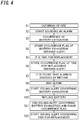
- step S1 When the control unit 10 determines the outbreak of the "fire” (step S1), the control unit 10 starts alarming about the "fire” (step S2). It is assumed that the control unit 10 determines that the "battery exhaustion” also occurs while the alarm sound is emitted (step S3). In a state where the residual capacity of the battery 13 is initially small, emission of the alarm sound may rapidly increase power consumption, and during the emission of the alarm sound, the residual capacity may well become less than 10%.
- control unit 10 since the control unit 10 is alarming about the presence of the "fire” corresponding to the highest rank A, the control unit 10 foregoes issuance of the alert concerning the occurrence of the "battery exhaustion", stores only the occurrence flag of the "battery exhaustion” in the storage section 7 (step S4), and causes the alert to enter the standby state.
- control unit 10 subsequently determines that it is also the "time for replacement” during the emission of the alarm sound (step S5). However, since the control unit 10 is alarming about the presence of the "fire” corresponding to the highest rank A, the control unit 10 foregoes issuance of the alert concerning that it is the "time for replacement", stores only the occurrence flag of the "time for replacement” in the storage section 7 (step S6), and causes the alert to enter the standby state.
- step S7 If it is found that the alarm is sounded by mistake, and the resident 100 pushes the operating unit 3 (step S7), the control unit 10 stops emitting the alarm sound (step S8).
- step S8 the control unit 10 starts issuing alerts concerning these events.
- the control unit 10 starts issuing the alert concerning the "battery exhaustion” (step S9).
- the control unit 10 ends the alert response to the "battery exhaustion” and erases the occurrence flag of the "battery exhaustion” (step S11).
- the occurrence flag of the "time for replacement” is present in the storage section 7, and therefore, the control unit 10 starts issuing the alert concerning the time for replacement (step S12).
- the "time for replacement” is less urgent, only the alert flickering of the indicating lamp 15 starts, and only when an operation is given to the operating unit 3 flickering in red, a voice warning message is emitted. Note that also regarding to the alert concerning the "battery exhaustion", only the alert flickering of the indicating lamp 15 starts, and only when an operation is given to the operating unit 3, a voice warning message may be output.
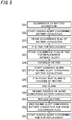
- step S21 When the control unit 10 determines that the "battery exhaustion" occurs (step S21), the control unit 10 starts issuing the alert concerning the "battery exhaustion” (step S22) and stores the occurrence flag of the "battery exhaustion” in the storage section 7 (step S23). It is assumed that the control unit 10 determines that it is also the "time for replacement” during the issuance of the alert concerning the "battery exhaustion” (step S24).
- control unit 10 since the control unit 10 is issuing the alert concerning the occurrence of the "battery exhaustion" corresponding to rank C, the control unit 10 foregoes issuance of the alert concerning that it is the "time for replacement” corresponding to rank D, stores only the occurrence flag of the "time for replacement” in the storage section 7 (step S25), and causes the alert to enter the standby state.
- control unit 10 subsequently determines that a "fire” is also present during the issuance of the alert concerning the "battery exhaustion” (step S26).
- the control unit 10 interrupts the alert concerning the "battery exhaustion” corresponding to rank C, allows interruption by the alarm about the "fire” corresponding to rank A, starts the alarm about the "fire” (step S27), and causes the alert concerning the "battery exhaustion” to enter in the standby state.
- step S28 If it is found that the alarm is sounded by mistake, and the resident 100 pushes the operating unit 3 (step S28), the control unit 10 stops emitting the alarm sound (step S29).
- step S29 At the end of the alert response to the fire, two occurrence flags are present in the storage section 7, and therefore, the control unit 10 starts issuing alerts concerning these events.
- the control unit 10 resumes issuance of the alert concerning the "battery exhaustion" (step S30).
- step S31 When the 100 notices the "battery exhaustion” and replaces the battery 13 (step S31), the control unit 10 ends the alert response to the “battery exhaustion” and erases the occurrence flag of the "battery exhaustion” (step S32). At the end of the alert response to the battery exhaustion, the occurrence flag of the "time for replacement" is present in the storage section 7, and therefore, the control unit 10 starts issuing the alert concerning this event (step S33).
- the alert concerning the fire is issued before the alert concerning the time for replacement is issued. This reduces cases where the fire that requires emission of an alarm sound is present, but the alert concerning the time for replacement is being issued, and the resident 100 can thus not be notified of the presence of the fire. Thus, reliability relating to the alert can be improved. In particular, since the alert concerning the fire corresponds to the highest priority and is thus issued before an alert concerning any internal event is issued, setting the alert concerning the fire to the highest rank among events including the internal events improves the reliability relating to the alert concerning the fire.
- the alert concerning the failure and the alert concerning the battery exhaustion other than the alert concerning the time for replacement are issued before the alert concerning the time for replacement.
- the alert concerning the time for replacement of the internal events which corresponds to a relatively low emergency level is set to the lowest priority rank, thereby improving the reliability relating to the alerts concerning the other events.
- an occurrence flag is stored. Therefore, even if a fire breaks out immediately before or during issuance of the alert concerning the presence of the internal event and interruption by an alert concerning the outbreak of the fire is allowed, the alert concerning the internal event can be resumed after the alert response to the fire ends. Alternatively, even if the internal event occurs during the issuance of the alert concerning the presence of a fire, the alert concerning the internal event is issued after the end of the alert response to the fire.
- the control unit 10 of the basic example starts the alert response to the internal event. That is, the control unit 10 of the basic example at least once determines that internal events are present, and the control unit 10 sequentially issues alerts concerning the internal events without abandoning the alerts. However, sequentially issuing the alerts concerning the internal events is not essential even when the occurrence flags are present.
- a control unit 10 of the present variation is configured to forego starting of an alert response to the internal event and forcibly erase an occurrence flag of the internal event even when the occurrence flag is present in a storage section 7 at the end of an alert response to a fire.
- the outbreak of a fire may be a more severe mental load for a resident 100 than the occurrence of any internal event. For example, if after the alarm about the fire is found to be sounded by mistake and the resident 100 is relieved and stops the alarm sound, an alert concerning an internal event with a lower emergency level than the fire is sequentially issued, the resident 100 may feel discomfort or anxiety.
- the control unit 10 makes a determination as to the internal event, for example, every one hour, the alert concerning the internal event is not issued until the next scheduled determination process.
- an occurrence flag of another internal event may be present, and in this case, the control unit 10 does not erase the occurrence flag and starts issuing an alert concerning the occurrence of the another internal event.
- storing the occurrence flag in the storage section 7 is not an essential configuration for the alarm 1. For example, even when the control unit 10 determines that it is the "time for replacement" corresponding to the lowest priority rank, the occurrence flag of the "time for replacement" does not have to be stored in the storage section 7.
- the alarm 1 according to the basic example is a fire alarm that operates independently. That is to say, the alarm 1 according to the basic example does not have the capability of communicating with other fire alarms. However, this is only an example of the present disclosure and should not be construed as limiting. Alternatively, the alarm 1 may also be an interconnected fire alarm with the capability of communicating with other fire alarms. In that case, the communication may be established either wirelessly or via cables, whichever is appropriate.
- the alarm 1 may also be configured to communicate various types of devices other than fire alarms. Examples of those devices other than fire alarms include cellphones (such as smartphones) carried by the resident 100 with him or her and security monitoring devices installed in the house.
- the alarm 1 may notify a portable terminal, a security monitoring apparatus, and the like of the presence of a fire, the occurrence of an internal event, and the like.
- dedicated application software is installed in the portable terminal, the security monitoring apparatus, and the like in advance.
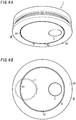
- the alarm 1 may have the structure shown in FIGS. 6A and 6B (according to a third variation).
- the alarm according to this variation includes a slit 9, which is annular, recessed upward, and provided through one surface 40 (e.g., the lower surface in FIG. 6A ) of the housing 4.
- the slit 9 is provided to extend along the circular outer periphery of the housing 4 when the housing 4 is looked up to from under the housing 4.
- the center of the slit 9, which is annular, substantially agrees with the center of the circular outer periphery of the housing 4.
- the slit 9 has, on its inner space (e.g., its inner bottom surface), a sound hole HI that allows the alarm sound to come out of the housing 4 and a window hole H2 that allows the illuminating light to come out of the housing 4.
- the first emission unit 11 (such as a loudspeaker) is housed in the housing 4 to face the sound hole HI.
- the second emission unit 12 is housed in the housing 4 to face the window hole H2.
- the sound hole HI and the window hole H2 are provided through an inner surface of the slit 9, thus making these holes less conspicuous. This allows the resident to be evacuated in an even shorter time while reducing the chances of affecting the appearance of the alarm.
- the functions of the alarm 1 may also be implemented as a control method, a computer program, or a non-transitory storage medium that stores the program.
- the alarm 1 or the agent that carries out the control method includes a computer system.
- the computer system includes, as principal hardware components, a processor and a memory.
- the functions of the alarm 1 or the agent that carries out the control method may be performed by making the processor execute a program stored in the memory of the computer system.
- the program may be stored in advance in the memory of the computer system.
- the program may also be downloaded through a telecommunications line or be distributed after having been recorded in some non-transitory storage medium such as a memory card, an optical disc, or a hard disk drive, any of which is readable for the computer system.
- the processor of the computer system may be made up of a single or a plurality of electronic circuits including a semiconductor integrated circuit (IC) or a largescale integrated circuit (LSI). Those electronic circuits may be either integrated together on a single chip or distributed on multiple chips, whichever is appropriate. Those multiple chips may be integrated together in a single device or distributed in multiple devices without limitation.
- IC semiconductor integrated circuit
- LSI largescale integrated circuit
- control unit 10 not only determines whether or not a fire is present but also makes a determination as to an internal event, generates the PWM signal to be output to the audio circuit and a control signal to be output to the lighting circuit, for example.
- this is only an example of the present disclosure and should not be construed as limiting.
- these functions may also be separately performed by two or more processors.
- the first lighting circuit and the second lighting circuit may also be implemented as a single lighting circuit.
- the alarm 1 according to the basic example is implemented as a single device. However, this is only an example of the present disclosure and should not be construed as limiting.
- at least one function of functions as the control unit 10, the first emission unit 11, the second emission unit 12, the fire detecting unit 2, the operating unit 3, the indicating lamp 15, the apparatus detecting unit 6, the storage section 7, the various types of circuit, and the like of the alarm 1 may be distributed in two or more devices.
- at least some of the functions of the alarm 1 may also be performed by a cloud computing system.
- an alarm (1) is to be installed in a structural component (C1).
- the alarm (1) includes an apparatus detecting unit (6), a control unit (10), and an alert unit (8).
- the apparatus detecting unit (6) is configured to detect first information corresponding to an internal event relating to the alarm (1) itself.
- the control unit (10) is configured to receive the first information to determine a presence or absence of the internal event.
- the control unit (10) is configured to receive second information relating to an external event that requires emission of an alarm sound to determine a presence or absence of the external event.
- the alert unit (8) is configured to issue an alert concerning the presence of the internal event and the presence of the external event.
- the internal event at least includes a time for replacement of the alarm (1).
- the control unit (10) is configured to cause the alert unit (8) to issue an alert concerning the external event with priority over an alert concerning the time for replacement.
- the first aspect reduces cases where the external event that requires emission of an alarm sound occurs, but the alert concerning the time for replacement is being issued, and a user can thus not be informed of the presence of the external event. Thus, reliability relating to the alert can be improved.
- the internal event preferably further includes one or more other events in addition to the time for replacement.
- the control unit (10) is preferably configured to cause the alert unit (8) to issue an alert concerning the one or more other events before the alert concerning the time for replacement.
- the alert concerning the time for replacement of the internal events which corresponds to a relatively low emergency level is set to the lowest priority rank, thereby improving the reliability relating to the alerts concerning the other events.
- the external event is preferably a fire.
- the control unit (10) is preferably configured to cause the alert unit (8) to issue an alert concerning the fire with priority over an alert concerning any internal event.
- setting the alert concerning the fire to the highest rank among events including the internal events improves the reliability relating to the alert concerning the fire.
- An alarm (1) of a fourth aspect referring to any one of the first to third aspects preferably further includes a storage section (7).
- the control unit (10) is preferably configured to, when determining that the internal event occurs, store an occurrence flag in the storage section (7).
- the control unit (10) is preferably configured to, when the occurrence flag is present in the storage section (7) at the end of an alert response to the external event, start an alert response to the internal event.
- the fourth aspect even if an interruption by an alert concerning the presence of an external event is allowed immediately before or during issuance of an alert concerning the presence of the internal event, the alert concerning the internal event is issued after the alert response to the external event ends.
- the alert concerning the internal event is issued after the alert response to the external event ends.
- An alarm (1) of a fifth aspect referring to any one of the first to third aspects preferably further includes a storage section (7).
- the control unit (10) is preferably configured to, when determining that the internal event occurs, store an occurrence flag in the storage section (7).
- the control unit (10) is preferably configured to forego starting of an alert response to the internal event and forcibly erase an occurrence flag of the internal event even when the occurrence flag is present in the storage section 7 at the end of an alert response to the external event.
- discomfort or anxiety for a user is reduced as compared to a case where, for example, an alarm concerning an internal event with a lower emergency level than the external event is sequentially issued after issuance of the alert concerning the external event ends.
- the control unit (10) is preferably configured to, when determining that a plurality of events of the external event and the internal event occur, perform alert responses to the plurality of events in the order of higher priority.
- the internal event preferably further includes a failure in the alarm (1) and battery exhaustion of a battery (a battery 13) in the alarm (1) as the plurality of events other than the time for replacement.
- the external event, the failure, the battery exhaustion, and the time for replacement are preferably defined in this order. According to the sixth aspect, alerts concerning all of the events that occur are sequentially issued, and therefore, the reliability relating to the alert is further improved.
- the external event is preferably a fire.
- the alarm (1) preferably further includes a fire detecting unit (2) configured to detect the outbreak of the fire.
- the control unit (10) preferably receives, as the information, a result of detection by the fire detecting unit (2) to determine whether or not the fire is present.
- the alarm (1) including the fire detecting unit (2) with improved reliability relating to the alert.
- a control method is a method for controlling an alarm (1) installed in a structural component (C1).
- the method includes a detecting step, a first determination step, a second determination step, and an alert step.
- the detection step includes detecting first information corresponding to an internal event relating to the alarm (1) itself.
- the first determination step includes receiving the first information to determine a presence or absence of the internal event.
- the second determination step includes receiving second information relating to an external event that requires emission of an alarm sound to determine a presence or absence of the external event.
- the alert step includes issuing an alert concerning a presence of the internal event and a presence of the external event.
- the internal event at least includes a time for replacement of the alarm (1).
- the alert step includes issuing an alert concerning the external event with priority over an alert concerning the time for replacement.
- the control method with improved reliability relating to the alert is provided.
- a program of a ninth aspect is designed to cause a computer system to carry out the control method of the eighth aspect.
- a function with improved reliability relating to the alert is provided.
- a non-transitory computer-readable medium may store the program. In that case, when the program is executed by a computer system, the computer system may carry out the control method of the eighth aspect.
- the configurations of the second to seventh aspects are not essential for the alarm (1) and may be omitted accordingly.
Landscapes
- Physics & Mathematics (AREA)
- General Physics & Mathematics (AREA)
- Fire Alarms (AREA)
- Alarm Systems (AREA)
- Fire-Detection Mechanisms (AREA)
Applications Claiming Priority (2)
| Application Number | Priority Date | Filing Date | Title |
|---|---|---|---|
| JP2018066193A JP2019175398A (ja) | 2018-03-29 | 2018-03-29 | 警報器、制御方法、及びプログラム |
| PCT/JP2019/010869 WO2019188423A1 (fr) | 2018-03-29 | 2019-03-15 | Alarme, procédé de commande et programme |
Publications (3)
| Publication Number | Publication Date |
|---|---|
| EP3779906A1 true EP3779906A1 (fr) | 2021-02-17 |
| EP3779906A4 EP3779906A4 (fr) | 2021-05-12 |
| EP3779906B1 EP3779906B1 (fr) | 2023-12-27 |
Family
ID=68058797
Family Applications (1)
| Application Number | Title | Priority Date | Filing Date |
|---|---|---|---|
| EP19776460.8A Active EP3779906B1 (fr) | 2018-03-29 | 2019-03-15 | Alarme, procédé de commande et programme |
Country Status (4)
| Country | Link |
|---|---|
| EP (1) | EP3779906B1 (fr) |
| JP (2) | JP2019175398A (fr) |
| TW (1) | TWI714033B (fr) |
| WO (1) | WO2019188423A1 (fr) |
Families Citing this family (3)
| Publication number | Priority date | Publication date | Assignee | Title |
|---|---|---|---|---|
| JP7072011B2 (ja) * | 2020-02-14 | 2022-05-19 | 新コスモス電機株式会社 | 警報器 |
| KR102617669B1 (ko) * | 2022-08-25 | 2023-12-27 | 김종범 | 위치 확인을 위한 음성 신호 발생 구조의 화재 경보 시스템 |
| JP7439337B1 (ja) | 2023-11-01 | 2024-02-27 | 新コスモス電機株式会社 | 警報器及び警報器の制御方法 |
Family Cites Families (19)
| Publication number | Priority date | Publication date | Assignee | Title |
|---|---|---|---|---|
| JP3925592B2 (ja) * | 1998-12-22 | 2007-06-06 | 能美防災株式会社 | 防災システム装置 |
| JP2000259959A (ja) * | 1999-03-05 | 2000-09-22 | Nittan Co Ltd | 火災報知設備 |
| AU765195B2 (en) * | 1999-05-25 | 2003-09-11 | Ranco Incorporated Of Delaware | Enhanced visual and audible signaling for sensed alarm condition |
| JP2008217824A (ja) * | 2003-09-08 | 2008-09-18 | Yazaki Corp | 警報器 |
| JP4325996B2 (ja) * | 2004-03-08 | 2009-09-02 | 能美防災株式会社 | 防災機器 |
| JP2005293204A (ja) * | 2004-03-31 | 2005-10-20 | Nohmi Bosai Ltd | 防災機器 |
| JP2005293307A (ja) * | 2004-03-31 | 2005-10-20 | Nohmi Bosai Ltd | 火災警報器 |
| JP4679225B2 (ja) * | 2005-04-28 | 2011-04-27 | 新コスモス電機株式会社 | 火災警報器および煙センサの交換時期演算方法 |
| JP5361205B2 (ja) | 2008-02-19 | 2013-12-04 | 能美防災株式会社 | 警報器 |
| JP5123104B2 (ja) | 2008-08-25 | 2013-01-16 | ホーチキ株式会社 | 警報器 |
| US8933811B2 (en) * | 2009-10-05 | 2015-01-13 | Cavius Aps | Smoke alarm |
| JP5534894B2 (ja) * | 2010-03-29 | 2014-07-02 | 能美防災株式会社 | 無線式警報システム |
| JP5608761B2 (ja) * | 2011-02-04 | 2014-10-15 | 富士電機株式会社 | 電池式警報器 |
| JP5804835B2 (ja) * | 2011-08-03 | 2015-11-04 | 能美防災株式会社 | 警報器 |
| JP6359851B2 (ja) * | 2014-03-25 | 2018-07-18 | 矢崎エナジーシステム株式会社 | 警報器及び通報システム |
| JP2016192117A (ja) | 2015-03-31 | 2016-11-10 | 能美防災株式会社 | 火災警報器 |
| US9685061B2 (en) * | 2015-05-20 | 2017-06-20 | Google Inc. | Event prioritization and user interfacing for hazard detection in multi-room smart-home environment |
| CN105931416B (zh) * | 2016-06-27 | 2018-03-16 | 宁波金盾电子工业股份有限公司 | 一种基于独立式光电感烟火灾探测报警器 |
| CN106952437A (zh) * | 2017-03-07 | 2017-07-14 | 上海伟梦物联网科技有限公司 | 一种消防信息检测系统及检测方法 |
-
2018
- 2018-03-29 JP JP2018066193A patent/JP2019175398A/ja not_active Ceased
-
2019
- 2019-03-15 WO PCT/JP2019/010869 patent/WO2019188423A1/fr not_active Ceased
- 2019-03-15 EP EP19776460.8A patent/EP3779906B1/fr active Active
- 2019-03-22 TW TW108109973A patent/TWI714033B/zh not_active IP Right Cessation
-
2022
- 2022-05-26 JP JP2022086349A patent/JP7555055B2/ja active Active
Also Published As
| Publication number | Publication date |
|---|---|
| EP3779906A4 (fr) | 2021-05-12 |
| WO2019188423A1 (fr) | 2019-10-03 |
| TW201942884A (zh) | 2019-11-01 |
| JP2019175398A (ja) | 2019-10-10 |
| TWI714033B (zh) | 2020-12-21 |
| JP7555055B2 (ja) | 2024-09-24 |
| JP2022105728A (ja) | 2022-07-14 |
| EP3779906B1 (fr) | 2023-12-27 |
Similar Documents
| Publication | Publication Date | Title |
|---|---|---|
| JP7555055B2 (ja) | 警報器、制御方法、及びプログラム | |
| EP3889789B1 (fr) | Système de commande, système de gestion d'appareil, procédé de commande, et programme | |
| EP3832615B1 (fr) | Dispositif de préparation aux catastrophes, procédé de commande et programme | |
| JP7706097B2 (ja) | 警報器 | |
| JP2020021262A (ja) | 警報システム、警報器、制御方法、及びプログラム | |
| TWI746946B (zh) | 音響裝置、控制方法及程式 | |
| JP6986695B2 (ja) | 照明器具及び照明システム | |
| EP3779913B1 (fr) | Dispositif audio, procédé de commande et programme | |
| JP7122705B2 (ja) | 防災機器、防災システム、制御方法、及びプログラム | |
| EP3779907B1 (fr) | Dispositif audio | |
| JP7213473B2 (ja) | 音響装置 | |
| JP7511190B2 (ja) | 機器 |
Legal Events
| Date | Code | Title | Description |
|---|---|---|---|
| STAA | Information on the status of an ep patent application or granted ep patent |
Free format text: STATUS: THE INTERNATIONAL PUBLICATION HAS BEEN MADE |
|
| PUAI | Public reference made under article 153(3) epc to a published international application that has entered the european phase |
Free format text: ORIGINAL CODE: 0009012 |
|
| STAA | Information on the status of an ep patent application or granted ep patent |
Free format text: STATUS: REQUEST FOR EXAMINATION WAS MADE |
|
| 17P | Request for examination filed |
Effective date: 20200923 |
|
| AK | Designated contracting states |
Kind code of ref document: A1 Designated state(s): AL AT BE BG CH CY CZ DE DK EE ES FI FR GB GR HR HU IE IS IT LI LT LU LV MC MK MT NL NO PL PT RO RS SE SI SK SM TR |
|
| AX | Request for extension of the european patent |
Extension state: BA ME |
|
| A4 | Supplementary search report drawn up and despatched |
Effective date: 20210413 |
|
| RIC1 | Information provided on ipc code assigned before grant |
Ipc: G08B 17/00 20060101AFI20210407BHEP Ipc: G08B 17/107 20060101ALI20210407BHEP |
|
| DAV | Request for validation of the european patent (deleted) | ||
| DAX | Request for extension of the european patent (deleted) | ||
| STAA | Information on the status of an ep patent application or granted ep patent |
Free format text: STATUS: EXAMINATION IS IN PROGRESS |
|
| 17Q | First examination report despatched |
Effective date: 20230203 |
|
| GRAP | Despatch of communication of intention to grant a patent |
Free format text: ORIGINAL CODE: EPIDOSNIGR1 |
|
| STAA | Information on the status of an ep patent application or granted ep patent |
Free format text: STATUS: GRANT OF PATENT IS INTENDED |
|
| INTG | Intention to grant announced |
Effective date: 20230718 |
|
| GRAS | Grant fee paid |
Free format text: ORIGINAL CODE: EPIDOSNIGR3 |
|
| GRAA | (expected) grant |
Free format text: ORIGINAL CODE: 0009210 |
|
| STAA | Information on the status of an ep patent application or granted ep patent |
Free format text: STATUS: THE PATENT HAS BEEN GRANTED |
|
| AK | Designated contracting states |
Kind code of ref document: B1 Designated state(s): AL AT BE BG CH CY CZ DE DK EE ES FI FR GB GR HR HU IE IS IT LI LT LU LV MC MK MT NL NO PL PT RO RS SE SI SK SM TR |
|
| REG | Reference to a national code |
Ref country code: GB Ref legal event code: FG4D |
|
| REG | Reference to a national code |
Ref country code: CH Ref legal event code: EP |
|
| REG | Reference to a national code |
Ref country code: DE Ref legal event code: R096 Ref document number: 602019044080 Country of ref document: DE |
|
| REG | Reference to a national code |
Ref country code: IE Ref legal event code: FG4D |
|
| PG25 | Lapsed in a contracting state [announced via postgrant information from national office to epo] |
Ref country code: GR Free format text: LAPSE BECAUSE OF FAILURE TO SUBMIT A TRANSLATION OF THE DESCRIPTION OR TO PAY THE FEE WITHIN THE PRESCRIBED TIME-LIMIT Effective date: 20240328 |
|
| REG | Reference to a national code |
Ref country code: LT Ref legal event code: MG9D |
|
| PG25 | Lapsed in a contracting state [announced via postgrant information from national office to epo] |
Ref country code: LT Free format text: LAPSE BECAUSE OF FAILURE TO SUBMIT A TRANSLATION OF THE DESCRIPTION OR TO PAY THE FEE WITHIN THE PRESCRIBED TIME-LIMIT Effective date: 20231227 |
|
| PG25 | Lapsed in a contracting state [announced via postgrant information from national office to epo] |
Ref country code: ES Free format text: LAPSE BECAUSE OF FAILURE TO SUBMIT A TRANSLATION OF THE DESCRIPTION OR TO PAY THE FEE WITHIN THE PRESCRIBED TIME-LIMIT Effective date: 20231227 |
|
| PG25 | Lapsed in a contracting state [announced via postgrant information from national office to epo] |
Ref country code: LT Free format text: LAPSE BECAUSE OF FAILURE TO SUBMIT A TRANSLATION OF THE DESCRIPTION OR TO PAY THE FEE WITHIN THE PRESCRIBED TIME-LIMIT Effective date: 20231227 Ref country code: GR Free format text: LAPSE BECAUSE OF FAILURE TO SUBMIT A TRANSLATION OF THE DESCRIPTION OR TO PAY THE FEE WITHIN THE PRESCRIBED TIME-LIMIT Effective date: 20240328 Ref country code: FI Free format text: LAPSE BECAUSE OF FAILURE TO SUBMIT A TRANSLATION OF THE DESCRIPTION OR TO PAY THE FEE WITHIN THE PRESCRIBED TIME-LIMIT Effective date: 20231227 Ref country code: ES Free format text: LAPSE BECAUSE OF FAILURE TO SUBMIT A TRANSLATION OF THE DESCRIPTION OR TO PAY THE FEE WITHIN THE PRESCRIBED TIME-LIMIT Effective date: 20231227 Ref country code: BG Free format text: LAPSE BECAUSE OF FAILURE TO SUBMIT A TRANSLATION OF THE DESCRIPTION OR TO PAY THE FEE WITHIN THE PRESCRIBED TIME-LIMIT Effective date: 20240327 |
|
| REG | Reference to a national code |
Ref country code: NL Ref legal event code: MP Effective date: 20231227 |
|
| REG | Reference to a national code |
Ref country code: AT Ref legal event code: MK05 Ref document number: 1645273 Country of ref document: AT Kind code of ref document: T Effective date: 20231227 |
|
| PG25 | Lapsed in a contracting state [announced via postgrant information from national office to epo] |
Ref country code: NL Free format text: LAPSE BECAUSE OF FAILURE TO SUBMIT A TRANSLATION OF THE DESCRIPTION OR TO PAY THE FEE WITHIN THE PRESCRIBED TIME-LIMIT Effective date: 20231227 |
|
| PG25 | Lapsed in a contracting state [announced via postgrant information from national office to epo] |
Ref country code: SE Free format text: LAPSE BECAUSE OF FAILURE TO SUBMIT A TRANSLATION OF THE DESCRIPTION OR TO PAY THE FEE WITHIN THE PRESCRIBED TIME-LIMIT Effective date: 20231227 Ref country code: RS Free format text: LAPSE BECAUSE OF FAILURE TO SUBMIT A TRANSLATION OF THE DESCRIPTION OR TO PAY THE FEE WITHIN THE PRESCRIBED TIME-LIMIT Effective date: 20231227 Ref country code: NO Free format text: LAPSE BECAUSE OF FAILURE TO SUBMIT A TRANSLATION OF THE DESCRIPTION OR TO PAY THE FEE WITHIN THE PRESCRIBED TIME-LIMIT Effective date: 20240327 Ref country code: NL Free format text: LAPSE BECAUSE OF FAILURE TO SUBMIT A TRANSLATION OF THE DESCRIPTION OR TO PAY THE FEE WITHIN THE PRESCRIBED TIME-LIMIT Effective date: 20231227 Ref country code: LV Free format text: LAPSE BECAUSE OF FAILURE TO SUBMIT A TRANSLATION OF THE DESCRIPTION OR TO PAY THE FEE WITHIN THE PRESCRIBED TIME-LIMIT Effective date: 20231227 Ref country code: HR Free format text: LAPSE BECAUSE OF FAILURE TO SUBMIT A TRANSLATION OF THE DESCRIPTION OR TO PAY THE FEE WITHIN THE PRESCRIBED TIME-LIMIT Effective date: 20231227 |
|
| PG25 | Lapsed in a contracting state [announced via postgrant information from national office to epo] |
Ref country code: IS Free format text: LAPSE BECAUSE OF FAILURE TO SUBMIT A TRANSLATION OF THE DESCRIPTION OR TO PAY THE FEE WITHIN THE PRESCRIBED TIME-LIMIT Effective date: 20240427 |
|
| PG25 | Lapsed in a contracting state [announced via postgrant information from national office to epo] |
Ref country code: AT Free format text: LAPSE BECAUSE OF FAILURE TO SUBMIT A TRANSLATION OF THE DESCRIPTION OR TO PAY THE FEE WITHIN THE PRESCRIBED TIME-LIMIT Effective date: 20231227 Ref country code: CZ Free format text: LAPSE BECAUSE OF FAILURE TO SUBMIT A TRANSLATION OF THE DESCRIPTION OR TO PAY THE FEE WITHIN THE PRESCRIBED TIME-LIMIT Effective date: 20231227 |
|
| PG25 | Lapsed in a contracting state [announced via postgrant information from national office to epo] |
Ref country code: SK Free format text: LAPSE BECAUSE OF FAILURE TO SUBMIT A TRANSLATION OF THE DESCRIPTION OR TO PAY THE FEE WITHIN THE PRESCRIBED TIME-LIMIT Effective date: 20231227 |
|
| PG25 | Lapsed in a contracting state [announced via postgrant information from national office to epo] |
Ref country code: SM Free format text: LAPSE BECAUSE OF FAILURE TO SUBMIT A TRANSLATION OF THE DESCRIPTION OR TO PAY THE FEE WITHIN THE PRESCRIBED TIME-LIMIT Effective date: 20231227 Ref country code: SK Free format text: LAPSE BECAUSE OF FAILURE TO SUBMIT A TRANSLATION OF THE DESCRIPTION OR TO PAY THE FEE WITHIN THE PRESCRIBED TIME-LIMIT Effective date: 20231227 Ref country code: RO Free format text: LAPSE BECAUSE OF FAILURE TO SUBMIT A TRANSLATION OF THE DESCRIPTION OR TO PAY THE FEE WITHIN THE PRESCRIBED TIME-LIMIT Effective date: 20231227 Ref country code: IT Free format text: LAPSE BECAUSE OF FAILURE TO SUBMIT A TRANSLATION OF THE DESCRIPTION OR TO PAY THE FEE WITHIN THE PRESCRIBED TIME-LIMIT Effective date: 20231227 Ref country code: IS Free format text: LAPSE BECAUSE OF FAILURE TO SUBMIT A TRANSLATION OF THE DESCRIPTION OR TO PAY THE FEE WITHIN THE PRESCRIBED TIME-LIMIT Effective date: 20240427 Ref country code: EE Free format text: LAPSE BECAUSE OF FAILURE TO SUBMIT A TRANSLATION OF THE DESCRIPTION OR TO PAY THE FEE WITHIN THE PRESCRIBED TIME-LIMIT Effective date: 20231227 Ref country code: CZ Free format text: LAPSE BECAUSE OF FAILURE TO SUBMIT A TRANSLATION OF THE DESCRIPTION OR TO PAY THE FEE WITHIN THE PRESCRIBED TIME-LIMIT Effective date: 20231227 Ref country code: AT Free format text: LAPSE BECAUSE OF FAILURE TO SUBMIT A TRANSLATION OF THE DESCRIPTION OR TO PAY THE FEE WITHIN THE PRESCRIBED TIME-LIMIT Effective date: 20231227 |
|
| PG25 | Lapsed in a contracting state [announced via postgrant information from national office to epo] |
Ref country code: PL Free format text: LAPSE BECAUSE OF FAILURE TO SUBMIT A TRANSLATION OF THE DESCRIPTION OR TO PAY THE FEE WITHIN THE PRESCRIBED TIME-LIMIT Effective date: 20231227 Ref country code: PT Free format text: LAPSE BECAUSE OF FAILURE TO SUBMIT A TRANSLATION OF THE DESCRIPTION OR TO PAY THE FEE WITHIN THE PRESCRIBED TIME-LIMIT Effective date: 20240429 |
|
| PG25 | Lapsed in a contracting state [announced via postgrant information from national office to epo] |
Ref country code: PT Free format text: LAPSE BECAUSE OF FAILURE TO SUBMIT A TRANSLATION OF THE DESCRIPTION OR TO PAY THE FEE WITHIN THE PRESCRIBED TIME-LIMIT Effective date: 20240429 Ref country code: PL Free format text: LAPSE BECAUSE OF FAILURE TO SUBMIT A TRANSLATION OF THE DESCRIPTION OR TO PAY THE FEE WITHIN THE PRESCRIBED TIME-LIMIT Effective date: 20231227 |
|
| REG | Reference to a national code |
Ref country code: DE Ref legal event code: R097 Ref document number: 602019044080 Country of ref document: DE |
|
| PG25 | Lapsed in a contracting state [announced via postgrant information from national office to epo] |
Ref country code: DK Free format text: LAPSE BECAUSE OF FAILURE TO SUBMIT A TRANSLATION OF THE DESCRIPTION OR TO PAY THE FEE WITHIN THE PRESCRIBED TIME-LIMIT Effective date: 20231227 |
|
| PG25 | Lapsed in a contracting state [announced via postgrant information from national office to epo] |
Ref country code: DK Free format text: LAPSE BECAUSE OF FAILURE TO SUBMIT A TRANSLATION OF THE DESCRIPTION OR TO PAY THE FEE WITHIN THE PRESCRIBED TIME-LIMIT Effective date: 20231227 |
|
| REG | Reference to a national code |
Ref country code: CH Ref legal event code: PL |
|
| PLBE | No opposition filed within time limit |
Free format text: ORIGINAL CODE: 0009261 |
|
| STAA | Information on the status of an ep patent application or granted ep patent |
Free format text: STATUS: NO OPPOSITION FILED WITHIN TIME LIMIT |
|
| PG25 | Lapsed in a contracting state [announced via postgrant information from national office to epo] |
Ref country code: LU Free format text: LAPSE BECAUSE OF NON-PAYMENT OF DUE FEES Effective date: 20240315 |
|
| PG25 | Lapsed in a contracting state [announced via postgrant information from national office to epo] |
Ref country code: MC Free format text: LAPSE BECAUSE OF FAILURE TO SUBMIT A TRANSLATION OF THE DESCRIPTION OR TO PAY THE FEE WITHIN THE PRESCRIBED TIME-LIMIT Effective date: 20231227 |
|
| GBPC | Gb: european patent ceased through non-payment of renewal fee |
Effective date: 20240327 |
|
| PG25 | Lapsed in a contracting state [announced via postgrant information from national office to epo] |
Ref country code: MC Free format text: LAPSE BECAUSE OF FAILURE TO SUBMIT A TRANSLATION OF THE DESCRIPTION OR TO PAY THE FEE WITHIN THE PRESCRIBED TIME-LIMIT Effective date: 20231227 Ref country code: LU Free format text: LAPSE BECAUSE OF NON-PAYMENT OF DUE FEES Effective date: 20240315 |
|
| 26N | No opposition filed |
Effective date: 20240930 |
|
| REG | Reference to a national code |
Ref country code: BE Ref legal event code: MM Effective date: 20240331 |
|
| PG25 | Lapsed in a contracting state [announced via postgrant information from national office to epo] |
Ref country code: BE Free format text: LAPSE BECAUSE OF NON-PAYMENT OF DUE FEES Effective date: 20240331 |
|
| PG25 | Lapsed in a contracting state [announced via postgrant information from national office to epo] |
Ref country code: GB Free format text: LAPSE BECAUSE OF NON-PAYMENT OF DUE FEES Effective date: 20240327 |
|
| PG25 | Lapsed in a contracting state [announced via postgrant information from national office to epo] |
Ref country code: FR Free format text: LAPSE BECAUSE OF NON-PAYMENT OF DUE FEES Effective date: 20240331 |
|
| PG25 | Lapsed in a contracting state [announced via postgrant information from national office to epo] |
Ref country code: IE Free format text: LAPSE BECAUSE OF NON-PAYMENT OF DUE FEES Effective date: 20240315 |
|
| PG25 | Lapsed in a contracting state [announced via postgrant information from national office to epo] |
Ref country code: IE Free format text: LAPSE BECAUSE OF NON-PAYMENT OF DUE FEES Effective date: 20240315 Ref country code: GB Free format text: LAPSE BECAUSE OF NON-PAYMENT OF DUE FEES Effective date: 20240327 Ref country code: FR Free format text: LAPSE BECAUSE OF NON-PAYMENT OF DUE FEES Effective date: 20240331 Ref country code: BE Free format text: LAPSE BECAUSE OF NON-PAYMENT OF DUE FEES Effective date: 20240331 Ref country code: CH Free format text: LAPSE BECAUSE OF NON-PAYMENT OF DUE FEES Effective date: 20240331 |
|
| PG25 | Lapsed in a contracting state [announced via postgrant information from national office to epo] |
Ref country code: SI Free format text: LAPSE BECAUSE OF FAILURE TO SUBMIT A TRANSLATION OF THE DESCRIPTION OR TO PAY THE FEE WITHIN THE PRESCRIBED TIME-LIMIT Effective date: 20231227 |
|
| PG25 | Lapsed in a contracting state [announced via postgrant information from national office to epo] |
Ref country code: CY Free format text: LAPSE BECAUSE OF FAILURE TO SUBMIT A TRANSLATION OF THE DESCRIPTION OR TO PAY THE FEE WITHIN THE PRESCRIBED TIME-LIMIT; INVALID AB INITIO Effective date: 20190315 |
|
| PG25 | Lapsed in a contracting state [announced via postgrant information from national office to epo] |
Ref country code: HU Free format text: LAPSE BECAUSE OF FAILURE TO SUBMIT A TRANSLATION OF THE DESCRIPTION OR TO PAY THE FEE WITHIN THE PRESCRIBED TIME-LIMIT; INVALID AB INITIO Effective date: 20190315 |
|
| PG25 | Lapsed in a contracting state [announced via postgrant information from national office to epo] |
Ref country code: TR Free format text: LAPSE BECAUSE OF FAILURE TO SUBMIT A TRANSLATION OF THE DESCRIPTION OR TO PAY THE FEE WITHIN THE PRESCRIBED TIME-LIMIT Effective date: 20231227 |
|
| PGFP | Annual fee paid to national office [announced via postgrant information from national office to epo] |
Ref country code: DE Payment date: 20260319 Year of fee payment: 8 |