WO2019188423A1 - Alarme, procédé de commande et programme - Google Patents
Alarme, procédé de commande et programme Download PDFInfo
- Publication number
- WO2019188423A1 WO2019188423A1 PCT/JP2019/010869 JP2019010869W WO2019188423A1 WO 2019188423 A1 WO2019188423 A1 WO 2019188423A1 JP 2019010869 W JP2019010869 W JP 2019010869W WO 2019188423 A1 WO2019188423 A1 WO 2019188423A1
- Authority
- WO
- WIPO (PCT)
- Prior art keywords
- notification
- control unit
- unit
- event
- fire
- Prior art date
- Legal status (The legal status is an assumption and is not a legal conclusion. Google has not performed a legal analysis and makes no representation as to the accuracy of the status listed.)
- Ceased
Links
Images

Classifications
-
- G—PHYSICS
- G08—SIGNALLING
- G08B—SIGNALLING SYSTEMS, e.g. PERSONAL CALLING SYSTEMS; ORDER TELEGRAPHS; ALARM SYSTEMS
- G08B7/00—Signalling systems according to two or more of groups G08B3/00 - G08B6/00
- G08B7/06—Signalling systems according to two or more of groups G08B3/00 - G08B6/00 using electric transmission, e.g. involving audible and visible signalling through the use of sound and light sources
-
- G—PHYSICS
- G08—SIGNALLING
- G08B—SIGNALLING SYSTEMS, e.g. PERSONAL CALLING SYSTEMS; ORDER TELEGRAPHS; ALARM SYSTEMS
- G08B17/00—Fire alarms; Alarms responsive to explosion
-
- G—PHYSICS
- G08—SIGNALLING
- G08B—SIGNALLING SYSTEMS, e.g. PERSONAL CALLING SYSTEMS; ORDER TELEGRAPHS; ALARM SYSTEMS
- G08B17/00—Fire alarms; Alarms responsive to explosion
- G08B17/10—Actuation by presence of smoke or gases, e.g. automatic alarm devices for analysing flowing fluid materials by the use of optical means
-
- G—PHYSICS
- G08—SIGNALLING
- G08B—SIGNALLING SYSTEMS, e.g. PERSONAL CALLING SYSTEMS; ORDER TELEGRAPHS; ALARM SYSTEMS
- G08B7/00—Signalling systems according to two or more of groups G08B3/00 - G08B6/00
- G08B7/06—Signalling systems according to two or more of groups G08B3/00 - G08B6/00 using electric transmission, e.g. involving audible and visible signalling through the use of sound and light sources
- G08B7/062—Signalling systems according to two or more of groups G08B3/00 - G08B6/00 using electric transmission, e.g. involving audible and visible signalling through the use of sound and light sources indicating emergency exits
-
- G—PHYSICS
- G08—SIGNALLING
- G08B—SIGNALLING SYSTEMS, e.g. PERSONAL CALLING SYSTEMS; ORDER TELEGRAPHS; ALARM SYSTEMS
- G08B7/00—Signalling systems according to two or more of groups G08B3/00 - G08B6/00
- G08B7/06—Signalling systems according to two or more of groups G08B3/00 - G08B6/00 using electric transmission, e.g. involving audible and visible signalling through the use of sound and light sources
- G08B7/066—Signalling systems according to two or more of groups G08B3/00 - G08B6/00 using electric transmission, e.g. involving audible and visible signalling through the use of sound and light sources guiding along a path, e.g. evacuation path lighting strip
Definitions
- the present disclosure generally relates to an alarm device, a control method, and a program, and more particularly to an alarm device that notifies that an external event such as a fire has occurred, a control method for the alarm device, and a program.
- a residential alarm device described in Patent Document 1 is illustrated.
- a smoke detector having a smoke inlet is opened at the center of the cover, and a fire is detected when smoke from the fire reaches a predetermined concentration.
- the house alarm has an acoustic hole on the lower left side of the smoke detection part in the cover, and a speaker is built in behind it to output an alarm sound and a voice message.
- the home alarm is installed on, for example, a wall surface of a living room or a bedroom of a house, and in the event of a fire, the fire is detected and an alarm is started.
- This disclosure is made in view of the above-described reasons, and an object thereof is to provide an alarm device, a control method, and a program capable of improving the reliability of notification.
- the alarm device is installed in the structure.
- the alarm device includes a device detection unit, a control unit, and a notification unit.
- the device detection unit detects first information corresponding to an internal event related to the alarm device itself.
- the control unit receives the first information to determine whether the internal event has occurred, and receives the second information regarding the external event that is the target of the alarm sound, to generate the external event. The presence or absence of is determined.
- the notification unit notifies the occurrence of the internal event and the occurrence of the external event.
- the internal event includes at least the replacement time of the alarm device.
- the control unit causes the notification unit to notify the external event prior to the notification of the replacement time.
- the control method is a control method for an alarm device installed in a structure.
- the control method includes a detection step, a first determination step, a second determination step, and a notification step.
- the detection step first information corresponding to an internal event related to the alarm device itself is detected.
- the first determination step the presence of the internal event is determined based on the first information.
- the second determination step it is determined whether or not the external event has occurred by receiving second information related to the external event that is the target of the alarm sound.
- the notification step the occurrence of the internal event and the occurrence of the external event are notified.
- the internal event includes at least the replacement time of the alarm device.
- the notification step the notification of the external event is performed prior to the notification of the replacement time.
- a program according to an aspect of the present disclosure is a program for causing a computer system to execute the control method.
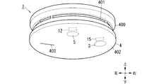
- FIG. 1 is an external view of an alarm device according to an embodiment.
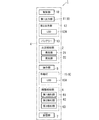
- FIG. 2 is a block diagram of the alarm device.
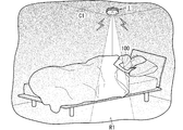
- FIG. 3 is a view showing a state of the bedroom where the alarm device is installed.
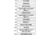
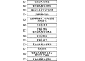
- FIG. 4 is a flowchart for explaining the operation of the alarm device.
- FIG. 5 is a flowchart for explaining the operation of the alarm device.
- 6A and 6B are external views of Modification 3 of the above-described acoustic device.
- the alarm device 1 of the present embodiment is installed in a structure C1 (a construction material such as a ceiling or a wall) as shown in FIG.
- the alarm device 1 includes a device detection unit 6, a control unit 10, and a notification unit 8.
- the device detection unit 6 detects first information corresponding to an internal event related to the alarm device 1 itself.
- the control unit 10 receives the first information and determines whether an internal event has occurred.
- the control unit 10 receives the second information related to the external event that is the target of the alarm sound, and determines whether or not the external event has occurred.
- the notification unit 8 notifies the occurrence of an internal event and the occurrence of an external event.
- internal event includes at least the replacement time of the alarm device 1 as an example.
- the internal event may include a failure in the alarm device 1 and a battery exhaustion.
- the alarm device 1 is, for example, a fire alarm device that outputs a sound such as an alarm sound when a fire occurs.
- the external event is not limited to a fire as long as it is an alarm sound, and may be a gas leak, a tsunami, an earthquake, a suspicious person intrusion, or the like.
- the alarm device 1 of the present embodiment further includes a photoelectric sensor (fire detection unit 2) that detects smoke inside, but the fire detection unit 2 detects heat.
- a constant temperature sensor may be used.
- the fire detection unit 2 may be a separate body from the alarm device 1.
- the control unit 10 of the alarm device 1 may receive the second information regarding the fire through communication with another alarm device (fire alarm device) provided with the fire detection unit 2.
- the alarm device 1 is installed on one surface (ceiling surface or wall surface) of the structure C1 such as a living room, a bedroom, a staircase, and a hallway in a house.
- the house may be a detached house or an apartment house (apartment).
- the alarm device 1 may be installed not only in a house but also in a non-residential structure C1 (ceiling surface or wall surface).
- Non-residential examples include office buildings, theaters, cinemas, public halls, amusement halls, complex facilities, restaurants, department stores, schools, hotels, inns, hospitals, nursing homes, kindergartens, libraries, museums, museums, underground malls, stations Including airports.
- the control unit 10 of the present embodiment causes the notification unit 8 to give a fire notification prior to the notification of the replacement time of the alarm device 1.
- the fire notification is performed prior to the replacement time notification. For this reason, it is possible to prevent the user from being notified of the occurrence of the fire because the low-urgent replacement time notification is being executed even though the fire that is the target of the alarm sound has occurred. Therefore, it is possible to improve the reliability related to notification.
- the alarm device 1 is a battery-type fire alarm device as an example.
- the alarm device 1 is a fire alarm device that is electrically connected to an external power source (for example, a commercial power system) and that is driven by converting AC power (for example, an effective value of 100 V) supplied from the external power source into a DC current. There may be.
- an external power source for example, a commercial power system
- AC power for example, an effective value of 100 V
- the alarm device 1 is installed on an indoor ceiling surface (one surface of the structure C1) in the residence of the resident 100 as an example.
- the vertical and horizontal directions of the alarm device 1 are defined and described using the vertical and horizontal arrows shown in FIG. These arrows are described only for the purpose of assisting the explanation, and are not accompanied by an entity. Further, these directions are not intended to limit the direction of use of the alarm device 1.
- the alarm device 1 includes, for example, a second output unit in addition to the control unit 10, the device detection unit 6, the notification unit 8 (the first output unit 11 and the operation lamp 15), and the fire detection unit 2. 12, a battery 13, an operation unit 3, a housing 4, and a translucent unit 5 (see FIG. 1).
- the alarm device 1 further includes a storage unit 7. As an example, it is assumed that the alarm device 1 is a stand-alone fire alarm device and does not have a communication function for communicating with other fire alarm devices.
- the case 4 includes a control unit 10, a device detection unit 6, a first output unit 11, a second output unit 12, a battery 13, a fire detection unit 2, an operation lamp 15, a storage unit 7, and A circuit board (not shown) on which circuit parts constituting the control unit 10 and various circuits are mounted is accommodated inside.
- a circuit board (not shown) on which circuit parts constituting the control unit 10 and various circuits are mounted is accommodated inside.
- the various circuits referred to here are, for example, an acoustic circuit, a first lighting circuit, a second lighting circuit, and a power circuit, which will be described later.
- the housing 4 is made of a synthetic resin, for example, a flame retardant ABS resin.
- the housing 4 is formed in a flat cylindrical shape as a whole.
- the housing 4 has an attachment portion on the upper surface thereof, and is attached to one surface (installation surface) of the structure C1 by the attachment portion.
- the housing 4 has a hole 401 in its peripheral wall 400 through which smoke can be introduced into the labyrinth provided in the housing 4.
- casing 4 has a partition wall which partitions the internal space into two upper and lower sides.
- the labyrinth and fire detection unit 2 is in the upper first space, and the control unit 10, the first output unit 11, the second output unit 12, the operation lamp 15, the circuit board, and the like are in the lower second space. .
- the casing 4 has a slit-like window hole 403 that is long in one direction (left-right direction in FIG. 1) on its lower wall (cover) 402.
- the window hole 403 is disposed to face the first output unit 11 accommodated in the housing 4.
- the window hole 403 guides the sound output from the first output unit 11 to the outside of the housing 4.
- the casing 4 supports the translucent part 5 so that the lower surface of the translucent part 5 is exposed to the outside of the casing 4 at the lower wall 402.
- the translucent part 5 is a disk-shaped member having translucency.
- the translucent portion 5 is formed of a material such as acrylic resin or glass.
- the translucent part 5 is disposed to face the second output part 12 accommodated in the housing 4.
- the translucent unit 5 guides the light emitted from the second output unit 12 to the outside of the housing 4.
- the light of the 2nd output part 12 may be called "illumination light"
- the light of the 2nd output part 12 is weakness compared with the illumination light which a general lighting fixture outputs, and the evacuation route Is enough to illuminate
- the translucent part 5 has a lens part whose outer surface is formed in a convex shape in order to distribute the light from the second output part 12 toward the surrounding region R1 such as the floor surface. Also good.
- a light guide member that efficiently guides light from the second output unit 12 to the translucent unit 5 may be provided between the translucent unit 5 and the second output unit 12.
- the housing 4 supports the operation unit 3 on the lower wall 402 so that the lower surface of the operation unit 3 is exposed to the outside of the housing 4.
- the operation unit 3 receives an operation input from the outside.
- the operation unit 3 can be pushed upward by a pressing operation with a user's finger or the like.
- the operation unit 3 is a disk-shaped member having translucency.
- the operation unit 3 is disposed to face the operating lamp 15 accommodated in the housing 4.
- the operation unit 3 is configured to push a push button switch (not shown) housed in the housing 4 by a push operation.
- the window hole 403 and the operation unit 3 sandwich the lower surface center of the lower wall 402 between the window hole 403 and the operation unit 3 when the lower surface of the lower wall 402 is viewed from below.
- they are arranged in one direction (left-right direction in FIG. 1).
- the translucent part 5 is disposed in front of the center of the lower surface of the lower wall 402 when the lower surface of the lower wall 402 is viewed from below.
- the notification unit 8 replaces the alarm device 1 that is an internal event (hereinafter simply referred to as “replacement time”), a failure in the alarm device 1 (hereinafter simply referred to as “failure”). ) And the occurrence of battery exhaustion (the remaining capacity of the battery 13 is a little remaining).
- the battery 13 is a lithium battery, for example.
- the notification unit 8 notifies the occurrence of an external event fire.
- both the first output unit 11 and the operation lamp 15 correspond to the notification unit 8, but only one of them may correspond to the notification unit 8.
- the first output unit 11 has a function of notifying the occurrence of an internal event and a function of notifying the occurrence of a fire.
- the first output unit 11 outputs sound (sound wave).
- the control unit 10 determines that a fire has occurred, the first output unit 11 outputs an alarm sound so as to notify the occurrence of the fire.
- the 1st output part 11 is constituted by a speaker which converts an electric signal into sound.
- the speaker has a diaphragm and emits an alarm sound by mechanically vibrating the diaphragm in accordance with an electrical signal.
- the speaker is formed in a circular shape when viewed from the front and has a disk shape.
- the first output unit 11 outputs an alarm sound (for example, “beep” sound) under the control of the control unit 10. It is preferable that the 1st output part 11 outputs a warning sound by changing the magnitude
- the alarm sound may include, for example, a sweep sound that is swept from a low tone to a high tone.
- the alarm sound may include a voice message such as “fire. Fire”.
- the alarm sound is composed of a sweep sound and a voice message continuous with the sweep sound.
- circuit components constituting an acoustic circuit are mounted on the circuit board.
- the acoustic circuit includes a low-pass filter and an amplifier.
- PWM Pulse Width Modulation
- the acoustic circuit receives a PWM (Pulse Width Modulation) signal corresponding to the alarm sound generated by the control unit 10 in the event of a fire, it converts it into a sinusoidal sound signal with a low-pass filter and amplifies it with an amplifier. To be output from the first output unit 11.
- PWM Pulse Width Modulation
- the first output unit 11 outputs a sound for notifying the occurrence of an internal event when the control unit 10 determines that any internal event has occurred.
- this sound may be referred to as “notification sound” in order to distinguish it from a warning sound at the time of fire.
- Example of notification sound regarding the replacement time includes a voice message such as “It is time to replace the alarm.” Also, an example of the notification sound relating to the failure includes a voice message such as “Beep, failure has occurred in“ XX ”.” Also, an example of the notification sound regarding the battery exhaustion includes a voice message such as “Please replace the battery.”
- the notification sound is output at a volume of about 60 to 70% of the volume of the alarm sound.
- the notification sound is repeatedly output periodically, for example, at an interval of 1 hour until the corresponding internal event is resolved.
- the first output unit 11 repeatedly outputs a message such as “Pip, please replace the battery” every 2 hours continuously, every 40 seconds until 1 hour passes. Outputs a beep sound.
- the first output unit 11 outputs a warning sound and a notification sound on a trial basis even during operation check.
- the operation check can be executed by pushing the operation unit 3 or pulling a pulling string (not shown) led out from the housing 4.
- the first output unit 11 stops outputting the alarm sound.
- the operation lamp 15 has a function for notifying the occurrence of an internal event and a function for notifying the occurrence of a fire.
- the operation lamp 15 includes a red LED (Light Emitting Diode) 15A mounted on the circuit board as a light source.
- the operation lamp 15 is turned off during normal times (when monitoring a fire), and starts blinking (or turned on) when the control unit 10 determines that a fire has occurred.
- the flashing to notify the occurrence of a fire is sometimes referred to as “operation flashing”.
- the operation blinking stops under the control of the control unit 10 when the alarm sound is stopped.
- circuit components constituting a first lighting circuit for causing the LED 15A of the operation lamp 15 to blink are mounted on the circuit board.
- the first lighting circuit blinks the LED 15 ⁇ / b> A using DC power discharged from the battery 13 under the control of the control unit 10.
- the first lighting circuit converts AC power supplied from the power system into DC current, and causes the LED 15A to blink.
- the light emitted from the operation lamp 15 is led out of the housing 4 through the operation unit 3 having translucency.
- the resident 100 can know that the alarm device 1 is operating (detecting a fire) by visually recognizing the red operation flashing of the operation unit 3.
- the operation lamp 15 When the control unit 10 determines that any internal event has occurred, the operation lamp 15 blinks to notify the occurrence of the internal event. Hereinafter, this blinking may be referred to as “notification blinking”.
- the operation lamp 15 performs notification flashing regardless of any of the replacement time, failure, and battery exhaustion.
- the first output unit 11 outputs a notification sound corresponding to an internal event that has actually occurred.
- the operation lamp 15 blinks even during operation inspection.
- the operation check of the operation lamp 15 can be executed by pushing the operation unit 3 or pulling the pull string.
- the 2nd output part 12 outputs the illumination light which illuminates surrounding area
- FIG. The second output unit 12 has one or a plurality of illumination white LEDs 12A mounted on the circuit board as a light source (see FIG. 2).
- the second output unit 12 is normally turned off, and starts lighting (output of illumination light) when the control unit 10 determines that a fire has occurred. Therefore, for example, even if a fire occurs at midnight when the resident 100 is sleeping, the resident 100 does not have to turn on the wall switch to turn on the lighting device. You can immediately evacuate by visually checking the evacuation route.
- the LED 12A is configured as a package type LED in which at least one LED chip is mounted at the center of the mounting surface of the flat mounting board.
- the LED chip is preferably a blue light emitting diode that emits blue light from the light emitting surface, for example.
- the mounting surface of the substrate including the LED chip is covered with a sealing resin mixed with a fluorescent material that converts the wavelength of blue light emitted from the LED chip.
- the LED 12A is configured to emit white illumination light from the light emitting surface when a DC voltage is applied between the anode electrode and the cathode electrode.
- the color of the illumination light is not limited to white, and other light colors may be used. However, it is desirable not to cover the light color of the operating lamp 15.
- a circuit component constituting a second lighting circuit for lighting the LED 12A of the second output unit 12 is mounted on the circuit board.
- the second lighting circuit lights the LED 12 ⁇ / b> A using DC power discharged from the battery 13 under the control of the control unit 10.
- the second lighting circuit converts the AC power supplied from the power system into a DC current and lights the LED 12A.
- the light (illumination light) emitted from the second output unit 12 is led to the outside of the housing 4 through the translucent unit 5, and the surrounding region R1 (here, the floor surface of the bedroom, the bed, etc.) Illuminated.
- the second output unit 12 is lit on a trial basis during operation inspection. Similar to the first output unit 11, the operation check of the second output unit 12 can be performed by pressing the operation unit 3 or pulling the pull string.
- the apparatus detection part 6 detects the 1st information corresponding to the internal event regarding the alarm device 1 itself.
- the internal event includes at least the replacement time of the alarm device 1 and, in addition to the replacement time, other events include a failure in the alarm device 1 and a battery exhaustion. Therefore, the first information includes the usage time corresponding to the replacement time, the information on the electrical or thermal physical quantity corresponding to the failure, the remaining capacity of the battery 13 corresponding to the battery exhaustion, and the like.
- the device detection unit 6 includes a first detection unit 61, a second detection unit 62, and a third detection unit 63. The first to third detection units 61 to 63 are electrically connected to the control unit 10.
- the first detection unit 61 has a timer for measuring the usage time corresponding to the replacement time.
- the usage time is, for example, 10 years.
- the first detector 61 measures the usage time and outputs information on the usage time to the control unit 10 as first information.
- the control unit 10 determines whether or not a replacement time has occurred based on the usage time information.
- the second detection unit 62 detects an electrical physical quantity corresponding to a failure, for example.
- the second detector 62 may detect a thermal physical quantity other than the electrical physical quantity.
- the “failure” referred to here corresponds to, for example, a failure of the fire detection unit 2, a failure of the acoustic circuit, a failure of the first and second lighting circuits, and a breakage of the electric wire in the container.
- the disconnection of the electric wire is, for example, the disconnection of the electric wire from the acoustic circuit to the first output unit 11.
- the 2nd detection part 62 detects the electrical physical quantity (electric current or voltage) in a predetermined electrical circuit, and outputs the electrical signal containing the physical quantity to the control part 10 as 1st information.
- the control unit 10 determines whether or not a failure has occurred based on the physical quantity information.
- the third detection unit 63 detects the remaining capacity of the battery 13. For example, the third detection unit 63 detects the battery voltage of the battery 13 corresponding to the remaining capacity, and outputs an electric signal including the battery voltage to the control unit 10 as first information. The control unit 10 determines whether or not the battery has run out based on the battery voltage information.
- the fire detection part 2 detects the 2nd information regarding the fire (external event) used as the alerting
- the fire detection part 2 is a photoelectric sensor which detects smoke as an example.
- the second information includes, for example, information regarding smoke.
- the fire detection unit 2 includes a light emitting unit 21 such as an LED and a light receiving unit 22 such as a photodiode.
- the light emitting unit 21 and the light receiving unit 22 are arranged in the labyrinth of the housing 4 so that the light receiving surface of the light receiving unit 22 deviates from the optical axis of the irradiation light of the light emitting unit 21. When a fire occurs, smoke can be introduced into the labyrinth through the hole 401 in the peripheral wall 400 of the housing 4.
- the fire detection unit 2 receives the irradiation light of the light emitting unit 21 scattered by the smoke by the light receiving unit 22.
- the fire detection unit 2 is electrically connected to the control unit 10.
- the fire detection unit 2 transmits an electric signal (detection signal) indicating a voltage level corresponding to the amount of light received by the light receiving unit 22 to the control unit 10.
- the control unit 10 determines the fire by converting the light amount of the detection signal received from the fire detection unit 2 into the smoke concentration (event level).
- the fire detection unit 2 may transmit a detection signal indicating a voltage level corresponding to the smoke concentration to the control unit 10 after converting the amount of light received by the light receiving unit 22 into a smoke concentration.
- the fire detection unit 2 may determine the occurrence of fire (smoke) from the amount of light received by the light receiving unit 22, and may transmit a detection signal including information that a fire has occurred to the control unit 10.
- the control unit 10 is composed of, for example, a microcomputer having a CPU (Central Processing Unit) and a memory as main components.
- the control unit 10 is realized by a computer having a CPU and a memory, and the computer functions as the control unit 10 when the CPU executes a program stored in the memory.
- the program is recorded in advance in the memory here, but may be provided by being recorded through a telecommunication line such as the Internet or in a non-temporary recording medium such as a memory card.
- the control unit 10 includes a first output unit 11, an acoustic circuit, a second output unit 12, an operation lamp 15, a first lighting circuit, a second lighting circuit, a fire detection unit 2, a device detection unit 6, a storage unit 7, and the like. Control.
- the control unit 10 also controls a power supply circuit that generates operating power for various circuits from the DC power of the battery 13.
- the storage unit 7 is a rewritable memory, and is preferably a nonvolatile memory.
- the storage unit 7 may be a memory included in the control unit 10 itself.
- the control unit 10 is configured to receive information on fire (second information) from the fire detection unit 2 and determine whether or not a fire has occurred.
- second information information on fire
- the control unit 10 monitors the detection signal (information) received from the fire detection unit 2 and determines whether or not the event level included in the detection signal exceeds a threshold value.
- the event level is the smoke density after conversion as an example.
- the event level may be a light amount.
- the control unit 10 stores a threshold value in the storage unit 7 or in its own memory.
- the control unit 10 may determine, for example, whether or not the smoke density periodically exceeds a threshold at a predetermined time interval, and may determine that a fire has occurred once the smoke density exceeds the threshold.
- the predetermined time interval is, for example, a 5-second interval.
- the control unit 10 may count the number of times that the smoke concentration has continuously exceeded the threshold, and may determine that a fire has occurred when the number of times reaches a specified number.
- the control part 10 receives the detection signal containing the information that the fire broke out from the fire detection part 2, you may determine that the fire broke out directly.
- the control unit 10 determines that a fire has occurred based on the smoke concentration, the control unit 10 starts to output an alarm sound from the first output unit 11. Specifically, the control unit 10 generates a PWM signal corresponding to a sweep sound whose frequency changes linearly with the passage of time, and outputs the PWM signal to the acoustic circuit. The PWM signal is converted into an audio signal by an acoustic circuit, and a sweep sound (alarm sound) is output from the first output unit 11. Further, the control unit 10 generates a PWM signal corresponding to the voice message based on the message data stored in the storage unit 7 or its own memory, and outputs the PWM signal to the acoustic circuit. The PWM signal is converted into an audio signal by an acoustic circuit, and an audio message (alarm sound) is output from the first output unit 11.
- the control unit 10 determines that a fire has occurred, the control signal for blinking the operation lamp 15 is sent to the first lighting circuit, and the control signal for lighting the second output unit 12 is sent to the second lighting circuit, respectively. Send.
- the first lighting circuit receives a control signal from the control unit 10, the first lighting circuit causes the operation lamp 15 to start operation blinking.
- the second lighting circuit lights the second output unit 12 with a certain brightness.
- the control unit 10 determines the smoke concentration even during an alarm (while an alarm sound is being issued). If the smoke concentration falls below the reference value during the alarm, the control unit 10 stops generating the PWM signal, stops the output of the alarm sound by the first output unit 11, and sends the stop signal to the first lighting circuit and The light is transmitted to the second lighting circuit, and the light output from the second output unit 12 and the operation lamp 15 is also stopped. That is, when the control unit 10 determines that the fire (smoke) has disappeared, the control unit 10 automatically stops the output of the alarm sound, the output of the illumination light, and the blinking of the operation lamp 15.
- control unit 10 stops the output of the alarm sound when the push button switch in the housing 4 is turned on by pressing the operation unit 3 during the alarm. If the resident 100 determines that the alarm of the alarm device 1 is a false alarm, the alarm sound can be stopped by pressing the operation unit 3. The alarm sound can be stopped by pulling the drawstring.
- the control unit 10 executes a predetermined operation test for operation check.
- the operation test includes a sound output test of the first output unit 11, a light output test of the second output unit 12, a blinking test of the operation lamp 15, and the like.
- the operation test can also be performed by pulling the drawstring.
- control unit 10 is configured to receive information on the internal event (first information) from the device detection unit 6 and determine whether or not an internal event has occurred. Hereinafter, the determination of whether or not an internal event has occurred will be described in detail.
- the control unit 10 monitors the usage time received from the first detection unit 61.
- the usage time is, for example, the time when the power is turned on and the alarm device 1 is in an operating state.
- the control unit 10 accumulates and stores the usage time received from the first detection unit 61 in the storage unit 7 or its own memory. When the accumulated usage time reaches 10 years, the control unit 10 determines that the replacement time has occurred, and notifies the operating lamp 15 that is the notification unit 8 of the replacement. That is, the operation lamp 15 starts blinking notification.
- the time for replacement is less urgent than battery exhaustion and failure, and replacement of the alarm device 1 is also convenient for the resident 100. Therefore, the control unit 10 does not output a voice message notifying the replacement time immediately after the determination from the first output unit 11, but outputs it only when the operation unit 3 that is blinking notification is pushed by the resident 100.
- the control unit 10 monitors information on the electrical physical quantity received from the second detection unit 62. For example, if the current value of the current flowing from the acoustic circuit to the first output unit 11 is an abnormal value (such as zero or a value close thereto), the control unit 10 determines that a disconnection has occurred. Moreover, if the voltage value of the predetermined electric circuit in various circuits is an abnormal value, the control unit 10 determines that a failure has occurred in the circuit. The control unit 10 may monitor information such as the temperature received from the second detection unit 62, and may determine that a failure has occurred if there is abnormal heat generation in various circuits.
- an abnormal value such as zero or a value close thereto
- the control unit 10 determines that a failure has occurred, the control unit 10 causes the first output unit 11 and the operation lamp 15 that are the notification unit 8 to be notified. That is, a voice message notifying the failure is output from the first output unit 11, and the operation lamp 15 starts blinking notification.
- the disconnection has arisen between the acoustic circuit and the 1st output part 11, since the alerting
- the control unit 10 monitors battery voltage information of the battery 13 received from the third detection unit 63.
- the control unit 10 previously stores characteristic data in which the battery voltage and the capacity of the battery 13 are associated with each other in the storage unit 7 or its own memory, and the remaining capacity corresponding to the received battery voltage is less than 10% of the capacity. If so, it is determined that the battery has run out.
- the control unit 10 determines that the battery has run out, the control unit 10 causes the first output unit 11 and the operation lamp 15 serving as the notification unit 8 to be notified. That is, a voice message notifying that the battery has run out is output from the first output unit 11, and the operation lamp 15 starts blinking notification.
- the control unit 10 determines whether or not an internal event has occurred in a predetermined cycle. For example, the determination of the internal event is performed once a day and at midnight.
- control unit 10 generates a PWM signal based on the message data stored in the storage unit 7 or its own memory, and responds via the acoustic circuit.
- a voice message is output from the first output unit 11.
- the resident 100 sleeping in the bedroom of the house wakes up from the bed in a state close to darkness after hearing an alarm sound and goes from the bed to the hallway. It may be difficult to instantaneously grasp the route and direction to the connected door.
- the resident 100 may go to the wall switch by searching in the dark and try to turn on the light in the bedroom. The action until the wall switch is turned on can lead to a delay in evacuation.
- the resident 100 is a hearing impaired person, for example, there is a possibility that the occurrence of a fire may not be noticed only by an alarm sound (sound).
- the alarm device 1 since the alarm device 1 outputs not only the alarm sound but also the illumination light of the second output unit 12, the resident 100 instantaneously takes a route (evacuation route) from the bed to the door connected to the hallway. And the possibility of saving time to turn on the lighting in the bedroom increases. Moreover, even if the resident 100 is a hearing impaired person, the possibility that a fire will be noticed by the illumination light of the second output unit 12 is increased. In short, since the alarm device 1 outputs not only an alarm sound but also illumination light, the evacuation time can be shortened.
- any two or more of fire, replacement time, failure, and battery exhaustion may occur at substantially the same timing.
- a replacement period may occur during a warning about the occurrence of a fire.
- a fire may occur while notifying that the battery has run out.
- another event of the internal event may occur while notifying the occurrence of any one of the internal events.
- the control unit 10 provides priority in order to notify these events, and causes the notification unit 8 to preferentially notify an event having a high priority.
- the control unit 10 causes the notification unit 8 to perform the fire notification prior to the notification of the replacement time.
- the control part 10 makes the alerting
- the control unit 10 causes the notification unit 8 to perform notification of any failure other than notification of replacement time and out of battery in the internal event prior to notification of replacement time.
- the priority is, for example, fire, failure, battery exhaustion, and replacement time from the highest.
- the storage unit 7 stores in advance priority information such as rank A for fire, rank B for failure, rank C for dead battery, and rank D for replacement. Rank A is the highest and rank D is the lowest priority.
- the control unit 10 interrupts notification of an event with a lower priority rank, and notifies an event with a higher priority rank. Interrupt and execute.
- the control unit 10 continues or starts notification of an event with a higher priority rank as it is. The low event notification is not immediately executed and the system waits for the turn.
- the control unit 10 determines that an internal event has occurred, the control unit 10 stores an occurrence flag in the storage unit 7.
- the storage unit 7 has, for example, storage areas for three generation flags corresponding respectively to replacement time, failure, and battery exhaustion.
- the control unit 10 writes the occurrence flag “1” in “0” of the storage area corresponding to the replacement time.
- the controller 10 starts the internal event alarm response. If two or more occurrence flags “1” exist in the storage unit 7, notification of an event with a high priority rank is started first. “Fire alarm response will end” is the situation when the alarm is false and the resident 100 presses the operation unit 3 to stop the alarm sound, and when the smoke concentration falls below the reference value, the alarm sound is automatically For example, when reporting is stopped.
- the occurrence flag in the storage unit 7 is deleted when the notification of the corresponding internal event is completed (rewritten from “1” to “0”).
- the situation where “internal event notification response is completed” is when the battery 13 is replaced, or when the disconnection is resolved.
- step S1 When the control unit 10 determines that a “fire” has occurred (step S1), a “fire” alarm is started (step S2). Assume that the control unit 10 determines that “battery exhaustion” has also occurred during the alarm sound (step S3). In a state where the remaining capacity of the battery 13 is originally relatively small, it is possible that the power consumption increases rapidly due to the alarm sound and the remaining capacity becomes less than 10% during the alarm sound. However, since the control unit 10 is in the alarm of the occurrence of “fire”, which is the highest rank A, the notification of the occurrence of “battery exhaustion” is not executed, and only the occurrence flag of “battery exhaustion” is stored in the storage unit 7. (Step S4), and the notification is put into a waiting state.
- Step S5 the control unit 10 further determines that the “exchange time” has occurred during the alarm sound.
- the control unit 10 is alarming the occurrence of “fire”, which is the highest rank A, the notification of the occurrence of “replacement time” is not executed, and only the occurrence flag of “replacement time” is stored in the storage unit 7. (Step S6), and the notification is put into a waiting state.
- step S7 If it is determined that the alarm is a false alarm and the resident 100 presses the operation unit 3 (step S7), the control unit 10 stops the alarm sound (step S8).
- the control unit 10 since there are two generation flags in the storage unit 7 at the time when the fire notification is completed, the control unit 10 starts these notifications. However, since the rank C “running out of battery” has a higher priority than the rank D “changing time”, the control unit 10 starts notification of “running out of battery” (step S9).
- the control unit 10 ends the “battery run out” notification response and deletes the “battery run out” flag (step S11). . Since the storage unit 7 has a “replacement time” generation flag at the time when the notification of the battery exhaustion is completed, the control unit 10 starts this notification (step S12). However, since the “replacement time” is less urgent, only the notification flashing of the operation lamp 15 is started, and a voice message is output only when the operation unit 3 flashing in red is operated. In addition, regarding the notification of “battery exhaustion”, only the notification blinking of the operation lamp 15 may be started, and a voice message may be output only when the operation unit 3 is operated.
- Step S21 When the control unit 10 determines that the occurrence of “battery depletion” has occurred (step S21), the control unit 10 starts notification of “battery depletion” (step S22), and stores the occurrence flag of “battery depletion” in the storage unit 7 ( Step S23). Assume that the control unit 10 determines that the “replacement time” has also occurred during the notification of “battery exhaustion” (step S24). However, since the control unit 10 is notifying the occurrence of “Battery out” of rank C, the control unit 10 does not perform the notification of the occurrence of “replacement time” of rank D and stores only the occurrence flag of “replacement time”. (Step S25), and the notification is put into a waiting state.
- control unit 10 further determines that a “fire” has occurred during the notification of “battery exhaustion” (step S26).
- the control unit 10 temporarily stops the notification of rank C “battery out”, interrupts and starts the rank A “fire” alarm (step S27), and also places the “battery out” notification in a waiting state. .
- step S28 If it is found that the alarm is a false alarm and the resident 100 presses the operation unit 3 (step S28), the control unit 10 stops the alarm sound (step S29).
- the control unit 10 since there are two generation flags in the storage unit 7 at the time when the notification of the fire is finished, the control unit 10 starts these notifications. However, since the priority of “Battery out” of rank C is higher than the “replacement time” of rank D, the control unit 10 resumes notification of “battery out” (step S30).
- step S31 When the resident 100 notices that the “battery has run out” and replaces the battery 13 (step S31), the control unit 10 ends the notification of “battery runout” and deletes the “battery runout” occurrence flag (step S32). . Since the storage unit 7 has a “replacement time” generation flag at the time when the notification of the battery exhaustion is completed, the control unit 10 starts this notification (step S33).
- the fire is notified before the replacement time is notified. For this reason, it is possible to suppress the fact that the notification of the replacement time is being executed and the resident 100 cannot be informed of the occurrence of the fire even though the fire that is the target of the alarm sound has occurred. Therefore, it is possible to improve the reliability related to notification.
- fire notifications are given the highest priority and prior to the notification of any internal event, so the priority of fire notification including internal events is made the highest priority to improve the reliability of fire notifications. be able to.
- any notification of failure or battery exhaustion other than notification of replacement time is performed prior to notification of replacement time. Even in an internal event, by setting the priority rank for notification of exchange time with relatively low urgency to the lowest level, it is possible to improve the reliability regarding notification of other events.
- an occurrence flag is stored. Therefore, even if a fire has occurred and interrupted the notification of the occurrence of a fire immediately before or during the notification of the occurrence of an internal event, the notification of the internal event must be resumed after the fire notification response has ended. Can do. Alternatively, even if an internal event has already occurred while notifying the occurrence of a fire, the internal event can be notified after the fire notification has been completed.
- the control unit 10 of this modification forcibly deletes the generation flag without starting the internal event notification response even if the generation flag exists in the storage unit 7 when the fire notification response ends. Is configured to do.
- the occurrence of a fire can be a mentally greater burden on the resident 100 than the occurrence of any internal event. For example, if an alarm is recognized as a false alarm and the resident 100 is relieved and stops the audible alarm, and if an internal event that is less urgent than a fire is continuously executed, the resident 100 will be discomforted or anxious. There is a possibility of giving a feeling. Therefore, the discomfort or anxiety given to the resident 100 can be suppressed by forcibly deleting the occurrence flag without starting the internal event notification response only when the fire notification response ends. If the control unit 10 determines the internal event at, for example, an hourly cycle, the internal event is not notified until the next regular determination process time.
- control unit 10 when another internal event occurrence flag is present when the notification of the internal event is finished, the control unit 10 does not delete the occurrence flag but generates the other internal event. Start notification.
- the configuration in which the generation flag is stored in the storage unit 7 is not an essential component for the alarm device 1.
- the control unit 10 may not store the occurrence flag in the storage unit 7 even if it determines that the “exchange time” with the lowest priority rank has occurred.
- the alarm device 1 of the basic example was a single type fire alarm device. That is, the alarm device 1 of the basic example does not have a communication function for communicating with other fire alarm devices. However, the alarm device 1 may be a linked fire alarm device having a communication function for communicating with other fire alarm devices. Communication may be performed wirelessly or may be performed by wire.
- the alarm device 1 may be configured to be able to communicate with devices other than the fire alarm device.
- Devices other than the fire alarm are, for example, a portable terminal (for example, a smartphone) carried by the resident 100, a security monitoring device installed in a house, and the like.
- the alarm device 1 may notify the mobile terminal, the security monitoring device, and the like of the occurrence of a fire and the occurrence of an internal event.
- dedicated application software is installed in advance in the mobile terminal and the security monitoring device.
- the alarm device 1 may have a structure as shown in FIGS. 6A and 6B (Modification 3).
- the alarm device of this modification has an annular slit 9 that is recessed upward on one surface 40 (lower surface in FIG. 6A) of the housing 4.
- the slit 9 is viewed from below the housing 4. Sometimes, it is formed along the circular outer periphery of the housing 4.
- the center of the annular slit 9 substantially coincides with the center of the circular outer periphery of the housing 4.
- the slit 9 has, on its inner surface (for example, the inner bottom surface), an acoustic hole H1 that guides an alarm sound to the outside of the housing 4 and a window hole H2 that guides illumination light to the outside of the housing 4. .
- the 1st output part 11 (speaker) is accommodated in the housing
- the second output unit 12 is accommodated in the housing 4 so as to face the window hole H2.
- the execution body of the alarm device 1 or the control method includes a computer system.
- the computer system mainly includes a processor and a memory as hardware.
- the processor executes the program recorded in the memory of the computer system, the function as the execution body of the alarm device 1 or the control method is realized.
- the program may be recorded in advance in the memory of the computer system, but may be provided through an electric communication line, or a non-transitory recording medium such as a memory card, optical disk, or hard disk drive that can be read by the computer system May be recorded and provided.
- a processor of a computer system includes one or more electronic circuits including a semiconductor integrated circuit (IC) or a large scale integrated circuit (LSI).
- the plurality of electronic circuits may be integrated on one chip, or may be distributed on the plurality of chips.
- the plurality of chips may be integrated into one device, or may be distributed and provided in a plurality of devices.
- control unit 10 performs not only determination of fire but also determination of internal events, generation of a PWM signal output to the acoustic circuit, generation of a control signal output to the lighting circuit, etc. These functions may be executed in a distributed manner by two or more processors, for example. Further, the first lighting circuit and the second lighting circuit may be configured as one lighting circuit, for example.
- the alarm device 1 of the basic example is realized by one device, but is not limited to this configuration.
- functions of the control unit 10, the first output unit 11, the second output unit 12, the fire detection unit 2, the operation unit 3, the operation lamp 15, the device detection unit 6, the storage unit 7 and various circuits of the alarm device 1 At least one of the functions may be distributed among two or more devices.
- at least a part of the functions of the alarm device 1 may be realized by, for example, cloud (cloud computing).
- the alarm device (1) includes a device detection unit (6), a control unit (10), and a notification unit (8).
- the device detection unit (6) detects first information corresponding to an internal event related to the alarm device (1) itself.
- the control unit (10) receives the first information and determines whether or not an internal event has occurred.
- the control unit (10) determines whether or not an external event has occurred in response to the second information related to the external event that is the target of the alarm sound.
- the notification unit (8) notifies the occurrence of an internal event and the occurrence of an external event.
- the internal event includes at least the replacement time of the alarm (1).
- the control unit (10) causes the notification unit (8) to notify the external event first with priority over the notification of the replacement time. According to the first aspect, in spite of the occurrence of an external event that is the target of the alarm sound, notification of the replacement time is in progress and the user cannot be notified of the occurrence of the external event. Can be suppressed. Therefore, it is possible to improve the reliability related to notification.
- the internal event preferably further includes one or more other events in addition to the replacement time.
- the control unit (10) causes the notification unit (8) to perform notification of any one or more other events prior to notification of the replacement time.
- reporting of another event can be aimed at by making the priority rank of alerting
- the external event is preferably a fire. It is preferable that the control unit (10) causes the notification unit (8) to perform the notification of fire prior to the notification of any internal event with the highest priority. According to the third aspect, it is possible to improve the reliability of fire notification by setting the priority rank of fire notification including the internal event to the highest rank.
- the alarm device (1) according to the fourth aspect further includes a storage unit (7) in any one of the first to third aspects.
- the control unit (10) determines that an internal event has occurred, it is preferable to store an occurrence flag in the storage unit (7).
- the control unit (10) preferably starts the internal event notification response if the occurrence flag is present in the storage unit (7) when the external event notification response ends.
- the internal event is notified after the response to the notification of the external event is completed. it can.
- the internal event can be notified after the external event notification is completed.
- the alarm device (1) according to the fifth aspect further includes a storage unit (7) in any one of the first to third aspects.
- the control unit (10) determines that an internal event has occurred, it is preferable to store an occurrence flag in the storage unit (7).
- the control unit (10) forces the generation flag without starting the internal event notification response even if the generation flag exists in the storage unit (7) when the external event notification response ends. It is preferable to erase them.
- the fifth aspect for example, after the notification of the external event is finished, compared to the case where the notification of the internal event that is less urgent than the external event is performed in succession, Pleasure or anxiety can be suppressed.
- the control unit (10) determines that a plurality of events among external events and internal events have occurred. When the determination is made, it is preferable to sequentially respond to notifications in order of priority. It is preferable that the internal event further includes a failure in the alarm device (1) and a battery (battery 13) built in the alarm device (1) as other events than the replacement time. From the highest priority, the priority is preferably an external event, failure, battery exhaustion, or replacement time. According to the sixth aspect, since all the events that have occurred are executed in order, the reliability regarding the notification can be further improved.
- the external event is preferably a fire.
- the alarm device (1) preferably further includes a fire detection unit (2) for detecting a fire.
- the control unit (10) preferably receives the detection result from the fire detection unit (2) as the information and determines whether or not a fire has occurred.
- the alarm device (1) with a fire detection part (2) which can aim at the improvement of the reliability regarding alerting
- the control method according to the eighth aspect is a control method for the alarm device (1) installed in the structure (C1).
- the control method includes a detection step, a first determination step, a second determination step, and a notification step.
- first information corresponding to an internal event related to the alarm device (1) itself is detected.
- the first determination step the first information is received to determine whether an internal event has occurred.
- the second determination step it is determined whether or not an external event has occurred in response to the second information related to the external event that is the target of the alarm sound.
- the notification step the occurrence of an internal event and the occurrence of an external event are notified.
- the internal event includes at least the replacement time of the alarm (1).
- the notification of the external event is performed prior to the notification of the exchange time.
- the control method which can aim at the improvement of the reliability regarding alerting
- the program according to the ninth aspect is a program for causing a computer system to execute the control method according to the eighth aspect.
- reporting can be provided.
- a non-transitory computer readable medium may store the above-described program and cause the computer system to execute the control method according to the eighth aspect when executed by the computer system.
- the configurations according to the second to seventh aspects are not essential to the alarm device (1) and can be omitted as appropriate.
Landscapes
- Physics & Mathematics (AREA)
- General Physics & Mathematics (AREA)
- Fire Alarms (AREA)
- Alarm Systems (AREA)
- Fire-Detection Mechanisms (AREA)
Abstract
La présente invention a pour objet d'améliorer la fiabilité relative à la notification. Une alarme (1) est disposée sur un corps structurel. L'alarme (1) est pourvue d'une unité de détection d'appareil (6), d'une unité de commande (10) et d'une unité de notification (8). L'unité de détection d'appareil (6) détecte des premières informations correspondant à un phénomène interne relatif à l'alarme (1) elle-même. Lors de la réception des premières informations, l'unité de commande (10) détermine si le phénomène interne s'est produit ou non. En outre, lors de la réception de secondes informations relatives à un phénomène externe, qui doit être un sujet d'activation d'alarme, l'unité de commande (10) détermine si le phénomène externe s'est produit ou non. L'unité de notification (8) notifie l'occurrence du phénomène interne et l'occurrence du phénomène externe. Le phénomène interne comprend au moins un temps d'échange de l'alarme (1). L'unité de commande (10) amène l'unité de notification (8) à notifier de préférence le phénomène externe avant la notification du temps d'échange.
Priority Applications (1)
| Application Number | Priority Date | Filing Date | Title |
|---|---|---|---|
| EP19776460.8A EP3779906B1 (fr) | 2018-03-29 | 2019-03-15 | Alarme, procédé de commande et programme |
Applications Claiming Priority (2)
| Application Number | Priority Date | Filing Date | Title |
|---|---|---|---|
| JP2018-066193 | 2018-03-29 | ||
| JP2018066193A JP2019175398A (ja) | 2018-03-29 | 2018-03-29 | 警報器、制御方法、及びプログラム |
Publications (1)
| Publication Number | Publication Date |
|---|---|
| WO2019188423A1 true WO2019188423A1 (fr) | 2019-10-03 |
Family
ID=68058797
Family Applications (1)
| Application Number | Title | Priority Date | Filing Date |
|---|---|---|---|
| PCT/JP2019/010869 Ceased WO2019188423A1 (fr) | 2018-03-29 | 2019-03-15 | Alarme, procédé de commande et programme |
Country Status (4)
| Country | Link |
|---|---|
| EP (1) | EP3779906B1 (fr) |
| JP (2) | JP2019175398A (fr) |
| TW (1) | TWI714033B (fr) |
| WO (1) | WO2019188423A1 (fr) |
Families Citing this family (3)
| Publication number | Priority date | Publication date | Assignee | Title |
|---|---|---|---|---|
| JP7072011B2 (ja) * | 2020-02-14 | 2022-05-19 | 新コスモス電機株式会社 | 警報器 |
| KR102617669B1 (ko) * | 2022-08-25 | 2023-12-27 | 김종범 | 위치 확인을 위한 음성 신호 발생 구조의 화재 경보 시스템 |
| JP7439337B1 (ja) | 2023-11-01 | 2024-02-27 | 新コスモス電機株式会社 | 警報器及び警報器の制御方法 |
Citations (7)
| Publication number | Priority date | Publication date | Assignee | Title |
|---|---|---|---|---|
| JP2000188787A (ja) * | 1998-12-22 | 2000-07-04 | Nohmi Bosai Ltd | 防災システム装置 |
| JP2000259959A (ja) * | 1999-03-05 | 2000-09-22 | Nittan Co Ltd | 火災報知設備 |
| JP2005251135A (ja) * | 2004-03-08 | 2005-09-15 | Nohmi Bosai Ltd | 防災機器 |
| JP2005293204A (ja) * | 2004-03-31 | 2005-10-20 | Nohmi Bosai Ltd | 防災機器 |
| JP2008217824A (ja) * | 2003-09-08 | 2008-09-18 | Yazaki Corp | 警報器 |
| JP2010049604A (ja) | 2008-08-25 | 2010-03-04 | Hochiki Corp | 警報器 |
| JP2011209837A (ja) * | 2010-03-29 | 2011-10-20 | Nohmi Bosai Ltd | 無線式警報システム |
Family Cites Families (12)
| Publication number | Priority date | Publication date | Assignee | Title |
|---|---|---|---|---|
| AU765195B2 (en) * | 1999-05-25 | 2003-09-11 | Ranco Incorporated Of Delaware | Enhanced visual and audible signaling for sensed alarm condition |
| JP2005293307A (ja) * | 2004-03-31 | 2005-10-20 | Nohmi Bosai Ltd | 火災警報器 |
| JP4679225B2 (ja) * | 2005-04-28 | 2011-04-27 | 新コスモス電機株式会社 | 火災警報器および煙センサの交換時期演算方法 |
| JP5361205B2 (ja) | 2008-02-19 | 2013-12-04 | 能美防災株式会社 | 警報器 |
| US8933811B2 (en) * | 2009-10-05 | 2015-01-13 | Cavius Aps | Smoke alarm |
| JP5608761B2 (ja) * | 2011-02-04 | 2014-10-15 | 富士電機株式会社 | 電池式警報器 |
| JP5804835B2 (ja) * | 2011-08-03 | 2015-11-04 | 能美防災株式会社 | 警報器 |
| JP6359851B2 (ja) * | 2014-03-25 | 2018-07-18 | 矢崎エナジーシステム株式会社 | 警報器及び通報システム |
| JP2016192117A (ja) | 2015-03-31 | 2016-11-10 | 能美防災株式会社 | 火災警報器 |
| US9685061B2 (en) * | 2015-05-20 | 2017-06-20 | Google Inc. | Event prioritization and user interfacing for hazard detection in multi-room smart-home environment |
| CN105931416B (zh) * | 2016-06-27 | 2018-03-16 | 宁波金盾电子工业股份有限公司 | 一种基于独立式光电感烟火灾探测报警器 |
| CN106952437A (zh) * | 2017-03-07 | 2017-07-14 | 上海伟梦物联网科技有限公司 | 一种消防信息检测系统及检测方法 |
-
2018
- 2018-03-29 JP JP2018066193A patent/JP2019175398A/ja not_active Ceased
-
2019
- 2019-03-15 WO PCT/JP2019/010869 patent/WO2019188423A1/fr not_active Ceased
- 2019-03-15 EP EP19776460.8A patent/EP3779906B1/fr active Active
- 2019-03-22 TW TW108109973A patent/TWI714033B/zh not_active IP Right Cessation
-
2022
- 2022-05-26 JP JP2022086349A patent/JP7555055B2/ja active Active
Patent Citations (7)
| Publication number | Priority date | Publication date | Assignee | Title |
|---|---|---|---|---|
| JP2000188787A (ja) * | 1998-12-22 | 2000-07-04 | Nohmi Bosai Ltd | 防災システム装置 |
| JP2000259959A (ja) * | 1999-03-05 | 2000-09-22 | Nittan Co Ltd | 火災報知設備 |
| JP2008217824A (ja) * | 2003-09-08 | 2008-09-18 | Yazaki Corp | 警報器 |
| JP2005251135A (ja) * | 2004-03-08 | 2005-09-15 | Nohmi Bosai Ltd | 防災機器 |
| JP2005293204A (ja) * | 2004-03-31 | 2005-10-20 | Nohmi Bosai Ltd | 防災機器 |
| JP2010049604A (ja) | 2008-08-25 | 2010-03-04 | Hochiki Corp | 警報器 |
| JP2011209837A (ja) * | 2010-03-29 | 2011-10-20 | Nohmi Bosai Ltd | 無線式警報システム |
Non-Patent Citations (1)
| Title |
|---|
| See also references of EP3779906A4 |
Also Published As
| Publication number | Publication date |
|---|---|
| EP3779906A1 (fr) | 2021-02-17 |
| EP3779906A4 (fr) | 2021-05-12 |
| TW201942884A (zh) | 2019-11-01 |
| JP2019175398A (ja) | 2019-10-10 |
| TWI714033B (zh) | 2020-12-21 |
| JP7555055B2 (ja) | 2024-09-24 |
| JP2022105728A (ja) | 2022-07-14 |
| EP3779906B1 (fr) | 2023-12-27 |
Similar Documents
| Publication | Publication Date | Title |
|---|---|---|
| JP7555055B2 (ja) | 警報器、制御方法、及びプログラム | |
| US20180211503A1 (en) | Systems and methods for intelligent lighting management with security applications | |
| JP7285497B2 (ja) | 機器管理システム、制御方法、及びプログラム | |
| JP7706097B2 (ja) | 警報器 | |
| EP3832615B1 (fr) | Dispositif de préparation aux catastrophes, procédé de commande et programme | |
| WO2016057761A2 (fr) | Systèmes et procédés pour la gestion d'un éclairage intelligent au moyen d'applications de sécurité | |
| JP2020021262A (ja) | 警報システム、警報器、制御方法、及びプログラム | |
| TWI746946B (zh) | 音響裝置、控制方法及程式 | |
| JP7122705B2 (ja) | 防災機器、防災システム、制御方法、及びプログラム | |
| JP7213473B2 (ja) | 音響装置 | |
| JP7511190B2 (ja) | 機器 | |
| TWI702573B (zh) | 音響裝置、音響裝置之控制方法及音響裝置之控制程式 | |
| JP7002006B2 (ja) | 音響装置 |
Legal Events
| Date | Code | Title | Description |
|---|---|---|---|
| 121 | Ep: the epo has been informed by wipo that ep was designated in this application |
Ref document number: 19776460 Country of ref document: EP Kind code of ref document: A1 |
|
| NENP | Non-entry into the national phase |
Ref country code: DE |
|
| WWE | Wipo information: entry into national phase |
Ref document number: 2019776460 Country of ref document: EP |
|
| ENP | Entry into the national phase |
Ref document number: 2019776460 Country of ref document: EP Effective date: 20201029 |