EP3780024A1 - Ruban d'alliage amorphe à base de fe et son procédé de production, noyau de fer et transformateur - Google Patents
Ruban d'alliage amorphe à base de fe et son procédé de production, noyau de fer et transformateur Download PDFInfo
- Publication number
- EP3780024A1 EP3780024A1 EP19778066.1A EP19778066A EP3780024A1 EP 3780024 A1 EP3780024 A1 EP 3780024A1 EP 19778066 A EP19778066 A EP 19778066A EP 3780024 A1 EP3780024 A1 EP 3780024A1
- Authority
- EP
- European Patent Office
- Prior art keywords
- amorphous alloy
- based amorphous
- laser irradiation
- alloy ribbon
- marks
- Prior art date
- Legal status (The legal status is an assumption and is not a legal conclusion. Google has not performed a legal analysis and makes no representation as to the accuracy of the status listed.)
- Withdrawn
Links
- 229910000808 amorphous metal alloy Inorganic materials 0.000 title claims abstract description 265
- XEEYBQQBJWHFJM-UHFFFAOYSA-N iron Substances [Fe] XEEYBQQBJWHFJM-UHFFFAOYSA-N 0.000 title claims description 585
- 238000004519 manufacturing process Methods 0.000 title description 17
- 238000005266 casting Methods 0.000 claims abstract description 68
- 230000004907 flux Effects 0.000 claims description 149
- 229910052742 iron Inorganic materials 0.000 claims description 142
- 238000012545 processing Methods 0.000 claims description 51
- 239000000463 material Substances 0.000 claims description 42
- 229910052796 boron Inorganic materials 0.000 claims description 40
- 229910052710 silicon Inorganic materials 0.000 claims description 40
- 238000000034 method Methods 0.000 claims description 28
- 238000004804 winding Methods 0.000 claims description 18
- 239000012535 impurity Substances 0.000 claims description 14
- 229920006395 saturated elastomer Polymers 0.000 claims description 11
- 238000005452 bending Methods 0.000 claims description 5
- 230000000052 comparative effect Effects 0.000 description 31
- 230000000694 effects Effects 0.000 description 29
- 239000000203 mixture Substances 0.000 description 28
- 239000000126 substance Substances 0.000 description 27
- 230000009467 reduction Effects 0.000 description 24
- 238000005259 measurement Methods 0.000 description 19
- 229910045601 alloy Inorganic materials 0.000 description 15
- 239000000956 alloy Substances 0.000 description 15
- 230000015572 biosynthetic process Effects 0.000 description 15
- 238000011156 evaluation Methods 0.000 description 12
- 230000000994 depressogenic effect Effects 0.000 description 11
- 239000011162 core material Substances 0.000 description 10
- 239000000835 fiber Substances 0.000 description 10
- 238000001816 cooling Methods 0.000 description 9
- 229910052751 metal Inorganic materials 0.000 description 8
- 239000002184 metal Substances 0.000 description 8
- FLDSMVTWEZKONL-AWEZNQCLSA-N 5,5-dimethyl-N-[(3S)-5-methyl-4-oxo-2,3-dihydro-1,5-benzoxazepin-3-yl]-1,4,7,8-tetrahydrooxepino[4,5-c]pyrazole-3-carboxamide Chemical compound CC1(CC2=C(NN=C2C(=O)N[C@@H]2C(N(C3=C(OC2)C=CC=C3)C)=O)CCO1)C FLDSMVTWEZKONL-AWEZNQCLSA-N 0.000 description 6
- 238000000879 optical micrograph Methods 0.000 description 6
- 238000002360 preparation method Methods 0.000 description 6
- 230000003247 decreasing effect Effects 0.000 description 5
- 238000003475 lamination Methods 0.000 description 5
- 238000005096 rolling process Methods 0.000 description 5
- 230000001629 suppression Effects 0.000 description 5
- 230000005284 excitation Effects 0.000 description 4
- 230000005381 magnetic domain Effects 0.000 description 4
- 238000010586 diagram Methods 0.000 description 3
- 229910001004 magnetic alloy Inorganic materials 0.000 description 3
- 230000003287 optical effect Effects 0.000 description 3
- 239000011248 coating agent Substances 0.000 description 2
- 238000000576 coating method Methods 0.000 description 2
- 238000005520 cutting process Methods 0.000 description 2
- 238000002844 melting Methods 0.000 description 2
- 230000008018 melting Effects 0.000 description 2
- 239000011347 resin Substances 0.000 description 2
- 229920005989 resin Polymers 0.000 description 2
- 238000012935 Averaging Methods 0.000 description 1
- ZOXJGFHDIHLPTG-UHFFFAOYSA-N Boron Chemical compound [B] ZOXJGFHDIHLPTG-UHFFFAOYSA-N 0.000 description 1
- 241000195480 Fucus Species 0.000 description 1
- 229910008423 Si—B Inorganic materials 0.000 description 1
- 238000010521 absorption reaction Methods 0.000 description 1
- 230000001154 acute effect Effects 0.000 description 1
- 229910052782 aluminium Inorganic materials 0.000 description 1
- 238000000137 annealing Methods 0.000 description 1
- 229910052790 beryllium Inorganic materials 0.000 description 1
- 229910052799 carbon Inorganic materials 0.000 description 1
- 230000008859 change Effects 0.000 description 1
- 238000006243 chemical reaction Methods 0.000 description 1
- 229910052804 chromium Inorganic materials 0.000 description 1
- 238000007796 conventional method Methods 0.000 description 1
- 239000013078 crystal Substances 0.000 description 1
- 230000006866 deterioration Effects 0.000 description 1
- 238000007688 edging Methods 0.000 description 1
- 238000002474 experimental method Methods 0.000 description 1
- 229910052733 gallium Inorganic materials 0.000 description 1
- 229910052732 germanium Inorganic materials 0.000 description 1
- 239000003365 glass fiber Substances 0.000 description 1
- 230000009477 glass transition Effects 0.000 description 1
- 229910052735 hafnium Inorganic materials 0.000 description 1
- JEIPFZHSYJVQDO-UHFFFAOYSA-N iron(III) oxide Inorganic materials O=[Fe]O[Fe]=O JEIPFZHSYJVQDO-UHFFFAOYSA-N 0.000 description 1
- 230000001678 irradiating effect Effects 0.000 description 1
- 238000013532 laser treatment Methods 0.000 description 1
- 229910052748 manganese Inorganic materials 0.000 description 1
- 229910052750 molybdenum Inorganic materials 0.000 description 1
- 229910052759 nickel Inorganic materials 0.000 description 1
- 229910052758 niobium Inorganic materials 0.000 description 1
- 230000010355 oscillation Effects 0.000 description 1
- 230000003647 oxidation Effects 0.000 description 1
- 238000007254 oxidation reaction Methods 0.000 description 1
- 230000001590 oxidative effect Effects 0.000 description 1
- 229910052760 oxygen Inorganic materials 0.000 description 1
- 229910052698 phosphorus Inorganic materials 0.000 description 1
- 230000002265 prevention Effects 0.000 description 1
- 238000007712 rapid solidification Methods 0.000 description 1
- 229910052761 rare earth metal Inorganic materials 0.000 description 1
- 239000010703 silicon Substances 0.000 description 1
- 238000009751 slip forming Methods 0.000 description 1
- 229910052717 sulfur Inorganic materials 0.000 description 1
- 229910052715 tantalum Inorganic materials 0.000 description 1
- 229910052719 titanium Inorganic materials 0.000 description 1
- 230000009466 transformation Effects 0.000 description 1
- 229910052723 transition metal Inorganic materials 0.000 description 1
- 150000003624 transition metals Chemical class 0.000 description 1
- 229910052720 vanadium Inorganic materials 0.000 description 1
- 229910052726 zirconium Inorganic materials 0.000 description 1
Images


Classifications
-
- H—ELECTRICITY
- H01—ELECTRIC ELEMENTS
- H01F—MAGNETS; INDUCTANCES; TRANSFORMERS; SELECTION OF MATERIALS FOR THEIR MAGNETIC PROPERTIES
- H01F1/00—Magnets or magnetic bodies characterised by the magnetic materials therefor; Selection of materials for their magnetic properties
- H01F1/01—Magnets or magnetic bodies characterised by the magnetic materials therefor; Selection of materials for their magnetic properties of inorganic materials
- H01F1/03—Magnets or magnetic bodies characterised by the magnetic materials therefor; Selection of materials for their magnetic properties of inorganic materials characterised by their coercivity
- H01F1/12—Magnets or magnetic bodies characterised by the magnetic materials therefor; Selection of materials for their magnetic properties of inorganic materials characterised by their coercivity of soft-magnetic materials
- H01F1/14—Magnets or magnetic bodies characterised by the magnetic materials therefor; Selection of materials for their magnetic properties of inorganic materials characterised by their coercivity of soft-magnetic materials metals or alloys
- H01F1/147—Alloys characterised by their composition
- H01F1/153—Amorphous metallic alloys, e.g. glassy metals
- H01F1/15308—Amorphous metallic alloys, e.g. glassy metals based on Fe/Ni
-
- C—CHEMISTRY; METALLURGY
- C22—METALLURGY; FERROUS OR NON-FERROUS ALLOYS; TREATMENT OF ALLOYS OR NON-FERROUS METALS
- C22C—ALLOYS
- C22C45/00—Amorphous alloys
- C22C45/02—Amorphous alloys with iron as the major constituent
-
- H—ELECTRICITY
- H01—ELECTRIC ELEMENTS
- H01F—MAGNETS; INDUCTANCES; TRANSFORMERS; SELECTION OF MATERIALS FOR THEIR MAGNETIC PROPERTIES
- H01F1/00—Magnets or magnetic bodies characterised by the magnetic materials therefor; Selection of materials for their magnetic properties
- H01F1/01—Magnets or magnetic bodies characterised by the magnetic materials therefor; Selection of materials for their magnetic properties of inorganic materials
- H01F1/03—Magnets or magnetic bodies characterised by the magnetic materials therefor; Selection of materials for their magnetic properties of inorganic materials characterised by their coercivity
- H01F1/12—Magnets or magnetic bodies characterised by the magnetic materials therefor; Selection of materials for their magnetic properties of inorganic materials characterised by their coercivity of soft-magnetic materials
- H01F1/14—Magnets or magnetic bodies characterised by the magnetic materials therefor; Selection of materials for their magnetic properties of inorganic materials characterised by their coercivity of soft-magnetic materials metals or alloys
- H01F1/147—Alloys characterised by their composition
- H01F1/153—Amorphous metallic alloys, e.g. glassy metals
- H01F1/15341—Preparation processes therefor
-
- H—ELECTRICITY
- H01—ELECTRIC ELEMENTS
- H01F—MAGNETS; INDUCTANCES; TRANSFORMERS; SELECTION OF MATERIALS FOR THEIR MAGNETIC PROPERTIES
- H01F27/00—Details of transformers or inductances, in general
- H01F27/24—Magnetic cores
- H01F27/25—Magnetic cores made from strips or ribbons
-
- H—ELECTRICITY
- H01—ELECTRIC ELEMENTS
- H01F—MAGNETS; INDUCTANCES; TRANSFORMERS; SELECTION OF MATERIALS FOR THEIR MAGNETIC PROPERTIES
- H01F41/00—Apparatus or processes specially adapted for manufacturing or assembling magnets, inductances or transformers; Apparatus or processes specially adapted for manufacturing materials characterised by their magnetic properties
- H01F41/02—Apparatus or processes specially adapted for manufacturing or assembling magnets, inductances or transformers; Apparatus or processes specially adapted for manufacturing materials characterised by their magnetic properties for manufacturing cores, coils, or magnets
- H01F41/0206—Manufacturing of magnetic cores by mechanical means
- H01F41/0213—Manufacturing of magnetic circuits made from strip(s) or ribbon(s)
- H01F41/0226—Manufacturing of magnetic circuits made from strip(s) or ribbon(s) from amorphous ribbons
Definitions
- the present disclosure relates to an Fe-based amorphous alloy ribbon and a method of producing the same, an iron core, and a transformer.
- Fe-based amorphous (non-crystalline) alloy ribbons have become increasingly popular as iron core materials for transformers.
- JP-A No. S61-29103 discloses, as a method of simultaneously improving iron loss and excitation properties of an Fe-based non-crystalline alloy, a method of improving magnetic properties of a non-crystalline alloy ribbon, the method involving locally and instantaneously melting the surface of a non-crystalline alloy ribbon, then rapidly solidifying and non-crystallizing again the ribbon, and thereafter annealing the ribbon.
- S61-29103 discloses, as measures for locally melting the surface of a non-crystalline alloy ribbon, a laser beam focused to a beam diameter of 0.5 mm ⁇ or less, a pulsed laser beam having a beam diameter of 0.5 mm ⁇ or less, and pulsed laser having a beam diameter of 0.3 mm ⁇ or less and an energy density per single pulse, of from 0.02 to 1.0 J/mm 2 .
- WO 2011/030907 discloses, as a soft magnetic amorphous alloy ribbon low in iron loss and apparent power and high in lamination factor, a soft magnetic amorphous alloy ribbon produced by a rapid solidification method, the alloy ribbon having, in the surface thereof, rows in the width direction, of depressed portions formed by a laser beam, at a predetermined interval in the longitudinal direction, in which each annular projected portion is formed around such each depressed portion, and such each annular projected portion not only has a smooth surface having thereon substantially no scattered alloy molten by laser beam irradiation, but also has a height t 2 of 2 ⁇ m or less and a ratio t 1 /T in a range of from 0.025 to 0.18, the ratio being the ratio of the depth ti of such each depressed portion to the thickness T of the ribbon, whereby the soft magnetic amorphous alloy ribbon has a low iron loss and a low apparent power.
- WO 2012/102379 discloses, as a rapidly quenched Fe-based soft magnetic alloy ribbon reduced in iron loss, a rapidly quenched Fe-based soft magnetic alloy ribbon, in which wavy irregularities are formed on a free surface, the wavy irregularities have width direction troughs arranged at almost constant intervals in the longitudinal direction, and the average amplitude D of the troughs is 20 mm or less.
- Paragraph 0022 in WO 2012/102379 describes "The rapidly quenched Fe-based soft magnetic alloy ribbon of the present invention has wavy irregularities formed on a free surface, the wavy irregularities have width direction troughs arranged at almost constant intervals in the longitudinal direction, and the average amplitude D of the troughs is 20 mm or less, not only the eddy-current loss is reduced, but also the hysteresis loss is suppressed, and the low iron loss is extremely low... ".
- the iron loss and the exciting power of an Fe-based amorphous alloy ribbon have been conventionally measured commonly in a condition of a magnetic flux density of 1.3 T (see, for example, respective Examples in JP-ANo. S61-29103 , WO 2011/030907 , and WO 2012/102379 ).
- Iron core materials for transformers are also demanded to be low in exciting power.
- An object of one aspect of the disclosure is to provide an Fe-based amorphous alloy ribbon reduced in iron loss in a condition of a magnetic flux density of 1.45 T and suppressed in an increase in exciting power in a condition of a magnetic flux density of 1.45 T, and a method of producing the Fe-based amorphous alloy ribbon.
- An object of another aspect of the disclosure is to provide an iron core and a transformer each having excellent performance by use of the Fe-based amorphous alloy ribbon according to the above one aspect.
- One aspect of the disclosure provides an Fe-based amorphous alloy ribbon reduced in iron loss in a condition of a magnetic flux density of 1.45 T and suppressed in an increase in exciting power in a condition of a magnetic flux density of 1.45 T, and a method of producing the Fe-based amorphous alloy ribbon.
- Another aspect of the disclosure provides an iron core and a transformer each having excellent performance by use of the Fe-based amorphous alloy ribbon according to the above one aspect.
- a numerical value range herein represented with “(from) ... to " means any range encompassing respective numerical values described before and after “to” as the lower limit and the upper limit, respectively.
- the upper limit value or the lower limit value described in a numerical value range as a numerical value range described stepwise in the disclosure may be replaced with the upper limit value or the lower limit value of other numerical value range described stepwise.
- the upper limit value or the lower limit value described in a numerical value range described in the disclosure may be replaced with respective values shown in Examples.
- step herein encompasses not only an independent step, but also a step that can achieve a predetermined object even in a case in which the step is not clearly distinguished from other steps.
- the Fe-based amorphous alloy ribbon herein refers to a ribbon consisting of an Fe-based amorphous alloy.
- the Fe-based amorphous alloy herein refers to an amorphous alloy containing Fe (iron) as a main component.
- the main component here refers to a component contained at the highest ratio (% by mass).
- the Fe-based amorphous alloy ribbon of the disclosure is an Fe-based amorphous alloy ribbon having a free solidified surface and a roll contact surface, in which the Fe-based amorphous alloy ribbon has plural laser irradiation mark rows each configured from plural laser irradiation marks on at least one surface of the free solidified surface or the roll contact surface; and in which the Fe-based amorphous alloy ribbon has:
- the Fe-based amorphous alloy ribbon of the disclosure (hereinafter, also simply referred to as "ribbon") has the above configuration, whereby the iron loss in a condition of a magnetic flux density of 1.45 T is reduced and an increase in exciting power in a condition of a magnetic flux density of 1.45 T is suppressed.
- the Fe-based amorphous alloy ribbon of the disclosure has plural laser irradiation mark rows each configured from plural laser irradiation marks on at least one surface of the free solidified surface or the roll contact surface, as described above.
- the Fe-based amorphous alloy ribbon of the disclosure has such laser irradiation mark rows, whereby a magnetic domain is segmentalized, thereby resulting in a reduction in iron loss in a condition of a magnetic flux density of 1.45 T.
- formation itself of the laser irradiation mark rows on the Fe-based amorphous alloy ribbon contributes to a reduction in iron loss in a condition of a magnetic flux density of 1.45 T.
- any laser irradiation mark on an Fe-based amorphous alloy ribbon may sometimes cause an increase in exciting power in a condition of a magnetic flux density of 1.45 T.
- Such an increase in exciting power in a condition of a magnetic flux density of 1.45 T is not desirable because a decrease in magnetic flux density B0.1 is caused.
- the Fe-based amorphous alloy ribbon of the disclosure is increased in spot interval and line interval between the laser irradiation marks to some extent and is reduced in the number of the laser irradiation marks to some extent (namely, is reduced in the number density of the laser irradiation marks to some extent).
- the Fe-based amorphous alloy ribbon of the disclosure is increased in spot interval and line interval between the laser irradiation marks to some extent and is reduced in the number density of the laser irradiation marks to some extent, and thus is suppressed in an increase in exciting power in a condition of a magnetic flux density of 1.45 T.
- the line interval can be measured by extending the laser irradiation mark rows to a position reaching the middle section in the width direction of the ribbon.
- a decrease in magnetic flux density B0.1 according to an increase in exciting power is also suppressed.
- the Fe-based amorphous alloy ribbon of the disclosure is reduced in iron loss in a condition of a magnetic flux density of 1.45 T and is suppressed in an increase in exciting power in a condition of a magnetic flux density of 1.45 T.
- the iron loss and the exciting power have been conventionally measured commonly in a condition of a magnetic flux density of 1.3 T.
- Examples in JP-A No. S61-29103 described above disclose a reduction in iron loss in a condition of a magnetic flux density of 1.3 T by irradiating the free solidified surface of an Fe-based amorphous alloy ribbon with YAG laser at a point sequence interval of 5 mm.
- Example 4 in WO 2011/030907 described above discloses reductions in iron loss and apparent power in a condition of a magnetic flux density of 1.3 T provided that, in a case in which the free solidified surface of an Fe-based amorphous alloy ribbon is irradiated with a laser beam, thereby forming depressed portion rows at an interval of 5 mm in the longitudinal direction, the ratio t 1/ T of the depth ti of such a depressed portion to the thickness T of the ribbon is from 0.025 to 0.18.
- the apparent power in WO 2011/030907 corresponds to the exciting power mentioned herein.
- Example 1 in WO 2012/102379 described above discloses reductions in iron loss and exciting power in a condition of a magnetic flux density of 1.3 T provided that wavy irregularities are formed on the free solidified surface of an Fe-based amorphous alloy ribbon, the wavy irregularities have width direction troughs arranged at almost constant intervals in the longitudinal direction, and the average amplitude of the troughs is 20 mm or less.
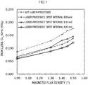
- Fig. 1 is a graph illustrating a relationship between a magnetic flux density and an iron loss with respect to each of four Fe-based amorphous alloy ribbons of an Fe-based amorphous alloy ribbon not laser-processed, an Fe-based amorphous alloy ribbon laser-processed at a spot interval of 0.05 mm, an Fe-based amorphous alloy ribbon laser-processed at a spot interval of 0.10 mm, and an Fe-based amorphous alloy ribbon laser-processed at a spot interval of 0.20 mm.
- the Fe-based amorphous alloy ribbon laser-processed at a spot interval of 0.05 mm is produced in the same conditions as in Comparative Example 2 described below except that the line interval is 60 mm.
- the Fe-based amorphous alloy ribbon laser-processed at a spot interval of 0.10 mm is produced in the same conditions as in Example 1 described below except that the line interval is 60 mm.
- the Fe-based amorphous alloy ribbon laser-processed at a spot interval of 0.20 mm is produced in the same conditions as in Example 3 described below (the line interval is 20 mm).
- the iron loss is reduced by subjecting the Fe-based amorphous alloy ribbons to laser processing in respective conditions of a spot interval of 0.05 mm, a spot interval of 0.10 mm, and a spot interval of 0.20 mm.
- Fig. 2 is a graph illustrating a relationship between a magnetic flux density and an exciting power with respect to each of the above four Fe-based amorphous alloy ribbons.
- the exciting power is rapidly increased at a magnetic flux density of more than 1.3 T. It can be seen that the Fe-based amorphous alloy ribbon at a spot interval of 0.05 mm is consequently remarkably high in exciting power in a condition of magnetic flux density of 1.45 T, as compared with such other three Fe-based amorphous alloy ribbons.
- the inventors have found as described above that the exciting power in a condition of magnetic flux density of 1.45 T is remarkably high in the case of a too narrow spot interval between the laser irradiation marks, for example, in the case of a spot interval of 0.05 mm (see Fig. 2 ).
- the inventors have also found that an increase in exciting power in a condition of magnetic flux density of 1.45 T can be suppressed by extending the spot interval to 0.10 mm or 0.20 mm (namely, decreasing the number density of the laser irradiation marks) (see Fig. 2 ).
- the inventors have also found that the effect of a reduction in iron loss by laser processing is obtained even by extending the spot interval to 0.10 mm or 0.20 mm (see Fig. 1 ).
- the inventors have also found that an increase in exciting power in a condition of a magnetic flux density of 1.45 T can be suppressed and the effect of a reduction in iron loss by laser processing can be obtained even by extending the line interval between such plural laser irradiation mark rows (specifically, allowing the line interval to be 10 mm or more) as in the case of extending of the spot interval.
- the iron loss has been conventionally reduced by forming wavy irregularities on the free solidified surface of an Fe-based amorphous alloy ribbon, as described in, for example, WO 2012/102379 above.
- Such wavy irregularities are also referred to as "chatter marks” or the like, and are generated due to paddle vibration in production (casting) of an Fe-based amorphous alloy ribbon (see, for example, paragraph 0008 in WO 2012/102379 ).
- Such wavy irregularities are intentionally formed on the free solidified surface by adjusting the production conditions of an Fe-based amorphous alloy ribbon in a technique for reducing the iron loss by formation of such wavy irregularities.
- an increase in the number density of laser irradiation marks can result in an increase in exciting power measured in a condition of a magnetic flux density of 1.45 T and have found that a decrease in the number density of laser irradiation marks can result in suppression of an increase in exciting power measured in a condition of a magnetic flux density of 1.45 T.
- the Fe-based amorphous alloy ribbon of the disclosure has been made based on such findings.
- the Fe-based amorphous alloy ribbon of the disclosure although is common to the techniques described in JP-ANo. S61-29103 and WO 2011/030907 in that laser irradiation marks are formed on the surface of the ribbon, is completely different from the techniques described in JP-ANo. S61-29103 and WO 2011/030907 in that the Fe-based amorphous alloy ribbon of the disclosure corresponds to a technique which is aimed at decreasing the number density of the laser irradiation marks and thus suppressing an increase in exciting power measured in a condition of a magnetic flux density of 1.45 T.
- the Fe-based amorphous alloy ribbon of the disclosure is an Fe-based amorphous alloy ribbon having a free solidified surface and a roll contact surface.
- the Fe-based amorphous alloy ribbon having a free solidified surface and a roll contact surface is a ribbon produced (cast) by a single roll method.
- the roll contact surface is a surface which is brought into contact with a cooling roll and rapidly solidified in casting
- the free solidified surface is a surface opposite to the roll contact surface (namely, a surface exposed to an atmosphere in casting).
- the Fe-based amorphous alloy ribbon of the disclosure may be a ribbon not cut after casting (for example, a rolled article wound up in the form of a roll after casting) or may be a ribbon piece cut out to a desired size after casting.
- the Fe-based amorphous alloy ribbon of the disclosure has plural laser irradiation mark rows each configured from plural laser irradiation marks on at least one surface of the free solidified surface or the roll contact surface.
- Each of the plural laser irradiation marks configuring such each laser irradiation mark row may be any mark as long as such any mark is one to which energy is applied by laser processing (namely, laser irradiation), and the shapes of such each laser irradiation mark (shape in planar view and cross-sectional shape) are not particularly limited.
- each of the plural laser irradiation marks is any mark to which energy is applied by laser irradiation, the effect of a reduction in iron loss by laser irradiation is obtained.
- the shape in planar view of such each laser irradiation mark may be any shape in planar view, such as a coronal, annular, or flat shape.
- the shape in planar view of such each laser irradiation mark is preferably an annular or flat shape, more preferably a flat shape from the viewpoints of weather resistance (rust prevention) of the laser irradiation marks in the Fe-based amorphous alloy ribbon and an enhancement in the lamination factor of the Fe-based amorphous alloy ribbon.
- a flat shape is adopted and such ribbons are layered to configure a magnetic core, the space between such ribbons can be suppressed and the ribbon density in the magnetic core can be enhanced.
- the Fe-based amorphous alloy ribbon of the disclosure has a line interval of from 10 mm to 60 mm in a case in which the line interval is defined as a centerline interval in a middle section in a width direction, between mutually adjacent laser irradiation mark rows of plural laser irradiation mark rows arranged in the casting direction of the Fe-based amorphous alloy ribbon, the width direction being orthogonal to the casting direction of the Fe-based amorphous alloy ribbon.
- the width direction is a direction orthogonal to the casting direction of the Fe-based amorphous alloy ribbon.
- the line interval is measured with such laser irradiation mark rows on such both surfaces, in the case of transmissive viewing of the ribbon, being targeted.
- such laser irradiation mark rows are formed alternately on such both surfaces in the casting direction of the ribbon, such "mutually adjacent laser irradiation mark rows" are directed to any laser irradiation mark rows which are formed on one surface and any laser irradiation mark rows which are formed on other surface and which are adjacent in the casting direction.
- the line interval is preferably from 10 mm to 50 mm, more preferably from 10 mm to 40 mm, still more preferably from 10 mm to 30 mm.
- the directions of plural such laser irradiation mark rows are preferably substantially parallel, but are not limited to be substantially parallel.
- the directions of plural such laser irradiation mark rows may be parallel or non-parallel as long as at least the line interval in the middle section in the width direction of the ribbon is from 10 mm to 60 mm.
- the "middle section in the width direction" of the Fe-based amorphous alloy ribbon can be each any portion having a certain width from the center in the width direction toward both ends in the width direction.
- a region in which the "certain width" from the center in the width direction toward both ends in the width direction corresponds to 1/4 of the entire width can be defined as such a middle section.
- a range in which the "certain width” corresponds to 1/2 of the entire width is more preferably defined as such a middle section.
- plural such laser irradiation mark rows need not to be necessarily arranged in parallel as long as the line interval in the middle section in the width direction of the Fe-based amorphous alloy ribbon is from 10 mm to 60 mm.
- An Fe-based amorphous alloy ribbon of one embodiment of the disclosure may have an arrangement relationship in which each direction of plural laser irradiation mark rows are not parallel to the width direction orthogonal to the casting direction of the Fe-based amorphous alloy ribbon.
- each direction of plural laser irradiation mark rows may be crossed at an inclined angle of an acute angle or an obtuse angle to the casting direction, while being at an angle of 10° or more to the width direction of the Fe-based amorphous alloy ribbon.
- each direction of plural laser irradiation mark rows is substantially parallel to the direction orthogonal to the casting direction and the thickness direction of the Fe-based amorphous alloy ribbon.
- Each direction of plural laser irradiation mark rows being substantially parallel to the direction orthogonal to the casting direction and the thickness direction of the Fe-based amorphous alloy ribbon means that the angle between each direction of plural laser irradiation mark rows and the direction orthogonal to the casting direction and the thickness direction of the Fe-based amorphous alloy ribbon is 10° or less.
- Such plural laser irradiation mark rows are not here limited to be substantially parallel.
- each direction of plural laser irradiation mark rows are substantially parallel to the width direction of the Fe-based amorphous alloy ribbon.
- Each direction of plural laser irradiation mark rows being substantially parallel to the width direction of the Fe-based amorphous alloy ribbon means that the angle between each direction of plural laser irradiation mark rows and the width direction of the Fe-based amorphous alloy ribbon is 10° or less.
- Such plural laser irradiation mark rows are not here limited to be substantially parallel.
- the Fe-based amorphous alloy ribbon of the disclosure may be an aspect in which the ribbon has, in the width direction thereof, one laser irradiation mark row with laser irradiation marks arranged at a constant interval in the width direction of the ribbon, or may be an aspect in which the ribbon has two or more of such laser irradiation mark rows.
- the Fe-based amorphous alloy ribbon of the disclosure may have plural laser irradiation mark rows arranged in the casting direction of the Fe-based amorphous alloy ribbon, as (1) an aspect of such any one row in the "middle section in the width direction" (hereinafter, referred to as "group of single row”.) or (2) an aspect of plural such any rows in the "middle section in the width direction" (hereinafter, referred to as "group of plural rows”.), in the width direction orthogonal to the casting direction.
- the latter group of plural rows has plural such groups of irradiation mark rows present in the in the width direction of the ribbon, the respective positions of the laser irradiation mark rows in plural such groups need not to be located on the same line in the width direction and may be in a positional relationship in which the laser irradiation mark rows are each displaced in the casting direction.
- the two groups may be in a positional relationship in which the groups are isolated by a region with no irradiation mark rows formed in the middle section in the width direction of the ribbon and plural laser irradiation mark rows arranged in one of the groups and plural laser irradiation mark rows arranged in another of the groups are alternately present each other with being displaced at a constant distance in the casting direction.
- the line interval in the disclosure is a value determined as follows.
- the line interval can be determined as an average value of measurement values obtained by measuring the interval between mutually adjacent two laser irradiation mark rows in the casting direction in the group of single row at five points arbitrarily selected.
- such plural laser irradiation mark rows configuring the group of single row are preferably present at a constant interval, and may be present at any interval.
- the line interval can be determined as a value obtained by further averaging the values (average values) determined with respect to respective "groups of irradiation mark rows" in the group of plural rows by the same method as the above procedure.
- such plural laser irradiation mark rows configuring such each "group of irradiation mark rows” are preferably present at a constant interval, and may be present at any interval.
- the Fe-based amorphous alloy ribbon of the disclosure has a spot interval of from 0.10 mm to 0.50 mm in a case in which the spot interval is defined as an interval between center points of plural laser irradiation marks in each of plural laser irradiation mark rows. Accordingly, spots continuously formed at a spot interval of less than 0.1 mm are not included.
- the spot interval is preferably from 0.15 mm to 0.40 mm, more preferably from 0.20 mm to 0.40 mm.
- the Fe-based amorphous alloy ribbon of the disclosure is more decreased in the number density of laser irradiation marks configuring each of laser irradiation mark rows, as compared with conventional one, and thus is suppressed in an increase in exciting power measured in a condition of a magnetic flux density of 1.45 T.
- the number density D is a value calculated from the line interval and the spot interval, and represents the density of the laser irradiation marks formed.
- the unit area is calculated from an area of a region in which the laser irradiation mark rows are formed in the width direction of the Fe-based amorphous alloy ribbon, and which has a length of 1 m in the casting direction or a length equal to an entire length in the casting direction when the length in the casting direction is less than 1 m.
- the number density D of the laser irradiation marks is a proper value (value lower than conventional one), whereby an increase in exciting power measured in a condition of a magnetic flux density of 1.45 T can be suppressed.
- the number density D of the laser irradiation marks configuring each of the laser irradiation mark rows is from 0.05 marks/mm 2 to 0.50 marks/mm 2 .
- the effect of a reduction in iron loss measured in a condition of a magnetic flux density of 1.45 T is more excellent.
- the effect of suppression of an increase in exciting power measured in a condition of a magnetic flux density of 1.45 T is more effectively exerted.
- the number density D of the laser irradiation marks configuring each of the laser irradiation mark rows is more preferably from 0.10 marks/mm 2 to 0.50 marks/mm 2 .
- the number density D can be determined as follows, depending on the case.
- the number density D is determined as the number density D by the above Formula, from the average value with respect to the line interval and the average value with respect to the spot interval determined by arbitrarily selecting five locations of "mutually adjacent laser irradiation mark rows" from plural laser irradiation mark rows, configuring the group of single row, and measuring line intervals and spot intervals to determine the respective average values.
- the number density D determined is in a range of from 0.05 marks/mm 2 to 0.50 marks/mm 2 , whereby the effects of the invention are exerted.
- the number density D is determined with respect to each "group of irradiation mark rows" in the group of plural rows by the same method as the above procedure.
- the number density D in at least one "group of irradiation mark rows" in the group of plural rows, among such number densities D determined, is in a range of from 0.05 marks/mm 2 to 0.50 marks/mm 2 , thereby allowing the effects to be exerted, and the average value of such number densities D determined is preferably in a range of from 0.05 marks/mm 2 to 0.50 marks/mm 2 and the number densities D in all the "groups of irradiation mark rows" in the group of plural rows are each more preferably in a range of from 0.05 marks/mm 2 to 0.50 marks/mm 2 , from the viewpoint that the effects of the invention are more exerted.
- the "casting direction” is here a direction corresponding to a circumferential direction of a cooling roll used in casting of the Fe-based amorphous alloy ribbon, and in other words, a direction corresponding to the longitudinal direction of the Fe-based amorphous alloy ribbon after casting and before cutting.
- a ribbon piece cut out can also be here confirmed about which direction the "casting direction" corresponds to, by observing the free solidified surface and/or the roll contact surface of the ribbon piece. For example, a thin stripe along with the casting direction is observed on the free solidified surface and/or the roll contact surface of the ribbon piece.
- the direction orthogonal to the casting direction is the width direction.
- the proportion of the length in the width direction of the laser irradiation mark rows in the entire length in the width direction of the Fe-based amorphous alloy ribbon is from 10% to 50% in each direction from the center in the width direction toward both ends in the width direction.
- "%" is defined under the assumption that the entire length in the width direction of the Fe-based amorphous alloy ribbon is 100%.
- the length of the laser irradiation mark rows is defined as not the length of the laser irradiation mark rows themselves inclined, but a value obtained by conversion into the length in the width direction of the ribbon, of a portion in which the laser irradiation mark rows are formed.
- a proportion of the length, of 50% means that the laser irradiation mark rows reach one end and other end in the width direction with the middle in the width direction of the Fe-based amorphous alloy ribbon, as a point of origin.
- the phrase "reach one end and other end in the width direction with the middle in the width direction of the Fe-based amorphous alloy ribbon, as a point of origin" means that the interval between any laser irradiation mark at an end of the laser irradiation mark rows and an end portion of the Fe-based amorphous alloy ribbon is equal to or less than the spot interval of the laser irradiation mark rows at both one end and other end.
- the entire length in the direction of the laser irradiation mark rows of the Fe-based amorphous alloy ribbon corresponds to the entire width of the Fe-based amorphous alloy ribbon.
- a proportion of the length, of 10% means that the length from the center in the width direction toward each of both ends in the width direction is 10%, in other words, means that laser irradiation mark rows having a length of 20% of the width length are included as a center region in the entire width. In other words, it is meant that laser irradiation mark rows are formed with any blank space being left by 40% with respect to the entire length in the width direction at both ends in the width direction of the Fe-based amorphous alloy ribbon.
- the proportion of the length in the width direction of the laser irradiation mark rows in the entire length in the width direction of the laser irradiation mark rows of the Fe-based amorphous alloy ribbon is more preferably 25% or more in each direction from the center in the width direction toward both ends in the width direction.
- the laser irradiation mark rows are still more preferably formed in six middle regions in the width direction that are regions other than two regions at both ends of eight regions obtained by equally dividing the Fe-based amorphous alloy ribbon into eight parts in the width direction.
- wavy irregularities are preferably reduced as much as possible from the viewpoint that an increase in exciting power measured in a condition of a magnetic flux density of 1.45 T is suppressed.
- the maximum cross-sectional height Rt on the free solidified surface excluding plural laser irradiation mark rows is preferably 3.0 ⁇ m or less.
- a maximum cross-sectional height Rt of 3.0 ⁇ m or less means that no wavy irregularities are present on the free solidified surface or wavy irregularities are reduced.
- the maximum cross-sectional height Rt on the free solidified surface excluding plural laser irradiation mark rows is obtained by subjecting a portion of the free solidified surface, the portion excluding plural laser irradiation mark rows, to measurement (evaluation) at an evaluation length of 4.0 mm and a cut-off value of 0.8 mm with a cut-off type as 2RC (phase compensation) according to JIS B 0601:2001.
- the direction of the evaluation length is here defined as the casting direction of the Fe-based amorphous alloy ribbon.
- the above measurement at an evaluation length of 4.0 mm is performed by performing the measurement particularly at a cut-off value of 0.8 mm continuously five times.
- the maximum cross-sectional height Rt on the free solidified surface excluding plural laser irradiation mark rows is more preferably 2.5 ⁇ m or less.
- the lower limit of the maximum cross-sectional height Rt is not particularly limited, and the lower limit of the maximum cross-sectional height Rt is preferably 0.8 ⁇ m, more preferably 1.0 ⁇ m from the viewpoint of production suitability of the Fe-based amorphous alloy ribbon.
- the chemical composition of the Fe-based amorphous alloy ribbon of the disclosure is not particularly limited, and may be a chemical composition (namely, any chemical composition with Fe (iron) as a main component) of an Fe-based amorphous alloy.
- the chemical composition of the Fe-based amorphous alloy ribbon of the disclosure is here preferably the following chemical composition A from the viewpoint that the effects of the Fe-based amorphous alloy ribbon of the disclosure are more effectively obtained.
- a chemical composition A as a preferable chemical composition is a chemical composition consisting of Fe, Si, B, and impurities, in which a content of Fe is 78 atom% or more, a content of B is 11 atom% or more, and a total content of B and Si is from 17 atom% to 22 atom% in a case in which a total content of Fe, Si, and B is 100 atom%.
- the content of Fe in the chemical composition A is 78 atom% or more.
- Fe (iron) is one of transition metals highest in magnetic moment even in an amorphous structure, and serves as a bearer of magnetic properties in an Fe-Si-B-based amorphous alloy.
- the saturated magnetic flux density (Bs) of the Fe-based amorphous alloy ribbon can be increased (for example, a Bs of about 1.6 T can be realized).
- a preferable magnetic flux density B0.1 (1.52 T or more) described below is also easily achieved.
- the content of Fe is preferably 80 atom% or more, still more preferably 80.5 atom% or more, still more preferably 81.0 atom% or more.
- the content is also preferably 82.5 atom% or less, still more preferably 82.0 atom% or less.
- the content of B in the chemical composition A is 11 atom% or more.
- B (boron) is an element contributing to amorphous formation. In a case in which the content of B is 11 atom% or more, amorphous formation ability is more enhanced.
- the content of B is preferably 12 atom% or more, still more preferably 13 atom% or more.
- the upper limit of the content of B is preferably 16 atom%, while depending on the total content of B and Si described below.
- the total content of B and Si in the chemical composition A is from 17 atom% to 22 atom%.
- Si is an element which is segregated, in the form of a molten metal, on a surface and thus has the effect of preventing oxidation of a molten metal. Si is also an element which acts as an aid for amorphous formation and thus has the effect of an increase in glass transition temperature, and which allows for formation of a more thermally stable amorphous phase.
- the content of Si is preferably 2.0 atom% or more, more preferably 2.4 atom% or more, still more preferably 3.5 atom% or more.
- the upper limit of the content of Si is preferably 6.0 atom%, while depending on the total content of B and Si.
- a more preferable chemical composition as the above chemical composition A of the Fe-based amorphous alloy ribbon consists of Fe, Si, B, and impurities, from the viewpoint of more improvements in iron loss and exciting power described below, in which the content of Fe is 80 atom% or more, the content of B is 12 atom% or more, and the total content of B and Si is from 17 atom% to 22 atom% in a case in which a total content of Fe, Si, and B is 100 atom%.
- the chemical composition A contains impurities.
- the chemical composition A may contain one or more impurities.
- impurities include any elements other than Fe, Si, and B, and specific examples include C, Ni, Co, Mn, O, S, P, Al, Ge, Ga, Be, Ti, Zr, Hf, V, Nb, Ta, Cr, Mo, and rare-earth elements.
- Such element(s) can be contained in a total amount range of 1.5% by mass with respect to the total mass of Fe, Si, and B.
- the upper limit of the total content of such element(s) is preferably 1.0% by mass or less, still more preferably 0.8% by mass or less, still more preferably 0.75% by mass or less.
- Such element(s) may be added in such any range.
- the thickness of the Fe-based amorphous alloy ribbon of the disclosure is not particularly limited, and the thickness is preferably from 20 ⁇ m to 35 ⁇ m.
- a thickness of 20 ⁇ m or more is advantageous in terms of suppression of waviness of the Fe-based amorphous alloy ribbon and then an enhancement in lamination factor.
- a thickness of 35 ⁇ m or less is advantageous in terms of embrittlement suppression and magnetic saturation properties of the Fe-based amorphous alloy ribbon.
- the thickness of the Fe-based amorphous alloy ribbon is more preferably from 20 ⁇ m to 30 ⁇ m .
- the Fe-based amorphous alloy ribbon of the disclosure is reduced in iron loss under conditions of a frequency of 60 Hz and a magnetic flux density of 1.45 T by segmentalization of a magnetic domain with laser processing (formation of laser irradiation marks).
- the iron loss under conditions of a frequency of 60 Hz and a magnetic flux density of 1.45 T is preferably 0.160 W/kg or less, more preferably 0.150 W/kg or less, still more preferably 0.140 W/kg or less, still more preferably 0.130 W/kg or less.
- the lower limit of the iron loss under conditions of a frequency of 60 Hz and a magnetic flux density of 1.45 T is not particularly limited, and the lower limit of the iron loss is preferably 0.050 W/kg from the viewpoint of production suitability of the Fe-based amorphous alloy ribbon.
- the iron loss of the Fe-based amorphous alloy ribbon is measured according to JIS 7152 (version in 1996).
- the Fe-based amorphous alloy ribbon of the disclosure is suppressed in an increase in exciting power in a condition of a magnetic flux density of 1.45 T.
- the exciting power under conditions of a frequency of 60 Hz and a magnetic flux density of 1.45 T is preferably 0.200 VA/kg or less, more preferably 0.170 VA/kg or less, still more preferably 0.165 VA/kg or less.
- the lower limit of the exciting power under conditions of a frequency of 60 Hz and a magnetic flux density of 1.45 is not particularly limited, and the lower limit of the exciting power is preferably 0.100 VA/kg from the viewpoint of production suitability of the Fe-based amorphous alloy ribbon.
- the Fe-based amorphous alloy ribbon of the disclosure is suppressed in an increase in exciting power in a condition of a magnetic flux density of 1.45 T and thus is suppressed in a reduction in magnetic flux density B0.1 according to an increase in exciting power, and as a result, the magnetic flux density B0.1 can be kept high.
- the magnetic flux density B0.1 under conditions of a frequency of 60 Hz and a magnetic field of 7.9557 A/m in the Fe-based amorphous alloy ribbon of the disclosure is preferably 1.52 T or more.
- the upper limit of the magnetic flux density B0.1 under conditions of a frequency of 60 Hz and a magnetic field of 7.9557 A/m is not particularly limited, and the upper limit is preferably 1.62 T.
- the Fe-based amorphous alloy ribbon of the disclosure can be suppressed to low iron loss and exciting power in a condition of a magnetic flux density of 1.45 T which is a higher magnetic flux density than a magnetic flux density of 1.3 T as a conventional condition.
- the iron loss and the exciting power can be suppressed even in the case of use at an operating magnetic flux density Bm where the ratio [operating magnetic flux density Bm/saturated magnetic flux density Bs] (hereinafter, also referred to as "Bm/Bs ratio”) is in a condition higher than conventional one.
- the Fe-based amorphous alloy ribbon of the disclosure is, for example, an Fe-based amorphous alloy ribbon having a chemical composition (Fe 82 Si 4 B 14 ) according to Example described below and having a Bs of 1.63 T.
- the Bs is almost unambiguously determined by the chemical composition.
- the Fe-based amorphous alloy ribbon of the disclosure can be here used at a Bm of 1.43 T or more (preferably from 1.45 T to 1.50 T).
- the Bm/Bs ratio is 0.88 in the case of a Bm of 1.43 T, and the Bm/Bs ratio is 0.92 in the case of a Bm of 1.50 T.
- the Fe-based amorphous alloy ribbon of the disclosure is particularly suitable for an application for use at an operating magnetic flux density Bm, in which a Bm/Bs ratio is from 0.88 to 0.94 (preferably from 0.89 to 0.92).
- the Fe-based amorphous alloy ribbon of the disclosure can also be suppressed in increases in iron loss and exciting power even in the case of use at an operating magnetic flux density Bm, in which a Bm/Bs ratio is from 0.88 to 0.94 (preferably from 0.89 to 0.92).
- the Fe-based amorphous alloy ribbon of the disclosure can be preferably produced by the following production method X.
- the production method X includes a step of preparing a material ribbon including an Fe-based amorphous alloy and having a free solidified surface and a roll contact surface (hereinafter, also referred to as "material preparation step"), and a step of forming plural laser irradiation mark rows each configured from plural laser irradiation marks on at least one surface of the free solidified surface or the roll contact surface of the material ribbon, by laser processing, thereby obtaining an Fe-based amorphous alloy ribbon having plural laser irradiation mark rows (hereinafter, also referred to as "laser processing step”), in which the Fe-based amorphous alloy ribbon has:
- the production method X may have, if necessary, any step other than the material preparation step and the laser processing step.
- the material preparation step in the production method X is a step of preparing a material ribbon having a free solidified surface and a roll contact surface.
- the material ribbon here mentioned may be a ribbon not cut after casting (for example, a rolled article wound up in the form of a roll after casting) or may be a ribbon piece cut out to a desired size after casting.
- the material ribbon is, per se, the Fe-based amorphous alloy ribbon of the disclosure before formation of laser irradiation marks.
- the free solidified surface and the roll contact surface of the material ribbon have the respective same meanings as the free solidified surface and the roll contact surface of the Fe-based amorphous alloy ribbon of the disclosure.
- a preferable aspect of the material ribbon (for example, a preferable chemical composition, a preferable Rt) is the same as a preferable aspect of the Fe-based amorphous alloy ribbon of the disclosure, except for the presence or absence of laser irradiation marks.
- the material preparation step may be a step of merely preparing such a material ribbon cast in advance (namely, already completed) for the purpose of subjecting to the laser processing step, or may be a step of newly casting such a material ribbon.
- the material preparation step may also be a step of performing at least one of casting of the material ribbon or cutting out of a ribbon piece from the material ribbon.
- the laser processing step in the production method X forms plural laser irradiation marks (particularly, each laser irradiation mark row configured from plural laser irradiation marks) on at least one surface of the free solidified surface or the roll contact surface of the material ribbon, by laser processing (namely, by laser irradiation).
- a preferable aspect of the laser irradiation marks and laser irradiation mark rows formed in the laser irradiation step is the same as a preferable aspect of the laser irradiation marks and laser irradiation mark rows in the Fe-based amorphous alloy ribbon of the disclosure.
- the laser conditions in the laser processing step are not particularly limited and are preferably as follows.
- the irradiation energy of a laser beam can be controlled with respect to the thickness of the Fe-based amorphous alloy ribbon, thereby allowing the diameter of a depressed portion and the depth of a depressed portion to be controlled.
- the pulse energy of laser for formation of each laser irradiation mark in the laser processing step (hereinafter, also referred to as "laser pulse energy”) is preferably from 0.4 mJ to 2.5 mJ, more preferably from 0.6 mJ to 2.5 mJ, still more preferably from 0.8 mJ to 2.5 mJ, still more preferably from 1.0 mJ to 2.0 mJ, still more preferably from 1.3 mJ to 1.8 mJ.
- the diameter of a laser beam (hereinafter, also referred to as “spot diameter”) is from 50 ⁇ m to 200 ⁇ m.
- the energy density is preferably from 0.01 J/mm 2 to 1.50 J/mm 2 , more preferably from 0.02 J/mm 2 to 1.30 J/mm 2 , still more preferably from 0.03 J/mm 2 to 1.02 J/mm 2 .
- the pulse width of laser is preferably 50 nsec or more, more preferably 100 nsec or more.
- the pulse width falls within the range, whereby magnetic characteristics, for example, the iron loss of a ribbon piece on which laser irradiation marks are formed, can be efficiently improved.
- the pulse width refers to a time during which laser irradiation is made, and a small pulse width means a short irradiation time.
- the entire energy of a laser beam for irradiation is represented by the product of the energy per unit time and the pulse width.
- a laser treatment is made by irradiation with a pulse laser beam scanned in the width direction of the ribbon in formation of a depressed portion.
- a laser beam source here used can be YAG laser, CO 2 gas laser, fiber laser, or the like.
- fiber laser is preferable in that irradiation with a high-power and high-frequency pulse laser beam can be stably made for a long time.
- Fiber laser allows a laser beam introduced into fibers to oscillate with diffraction gratings at both ends of the fibers by the principle of FBG (Fiber Bragg grating). Such a laser beam is excited in elongated fibers, and thus has no problem of the thermal lens effect due to deterioration in beam quality by the temperature gradient generated in crystals.
- Such a laser beam not only propagates in a single mode even at a high power, but also is narrowed down in beam diameter, due to a fiber core which is as thin as several microns, whereby a high-energy density laser beam is obtained.
- Such a laser beam is furthermore long in focus depth, and thus enables a depressed portion row to be accurately formed even on a wide ribbon of 200 mm or more.
- the pulse width of fiber laser is usually about microseconds to picoseconds.
- the laser beam wavelength is from about 250 nm to 1100 nm due to a laser beam source, and is suitably a wavelength of from 900 to 1100 nm because sufficient absorption is made in the alloy ribbon.
- the laser beam diameter is preferably 10 ⁇ m or more, more preferably 30 ⁇ m or more, more preferably 50 ⁇ m or more.
- the beam diameter is preferably 500 ⁇ m or less, more preferably 400 ⁇ m or less, more preferably 300 ⁇ m or less.
- the laser processing step may be a step of subjecting the material ribbon after casting by a single roll method and before winding up, to laser processing, may be a step of subjecting the material ribbon wound out from the material ribbon wound up (rolled article), to laser processing, or may be a step of subjecting a ribbon piece cut out from the material ribbon wound out from the material ribbon wound up (rolled article), to laser processing.
- the production method X is performed by using, for example, a system in which a laser processing apparatus is disposed between a cooling roll and a wind-up roll.
- the iron core of the disclosure is formed by layering plural the above-mentioned Fe-based amorphous alloy ribbons of the disclosure, specifically, by layering such Fe-based amorphous alloy ribbons, and bending and winding such Fe-based amorphous alloy ribbons layered in an overlapping manner, and the iron loss under conditions of a frequency of 60 Hz and a magnetic flux density of 1.45 T is 0.250 W/kg or less.
- the iron loss is preferably 0.230 W/kg or less, more preferably 0.200 W/kg or less, still more preferably 0.180 W/kg or less.
- the lower limit of the iron loss under conditions of a frequency of 60 Hz and a magnetic flux density of 1.45 T is not particularly limited, and the lower limit of the iron loss is preferably 0.050 W/kg, more preferably 0.080 W/kg from the viewpoint of production suitability of the Fe-based amorphous alloy ribbon.
- a known method can be applied to the method of winding in an overlapping manner.
- the shape of the iron core of the disclosure may be any of a round shape, a rectangular shape, or the like.
- the type or the like of a coil wound around the iron core is not limited, and may be appropriately selected from those known.
- the transformer of the disclosure includes an iron core using the above-mentioned Fe-based amorphous alloy ribbon of the disclosure, and a coil wound around the iron core, in which the iron core is formed by bending and winding the Fe-based amorphous alloy ribbon layered in an overlapping manner, and the iron loss under conditions of a frequency of 60 Hz and a magnetic flux density of 1.45 T is in a range of 0.250 W/kg or less.
- the iron loss under conditions of a frequency of 60 Hz and a magnetic flux density of 1.45 T in the transformer of the disclosure is 0.250 W/kg or less, preferably 0.230 W/kg or less, more preferably 0.200 W/kg or less, still more preferably 0.180 W/kg or less.
- the lower limit of the iron loss under conditions of a frequency of 60 Hz and a magnetic flux density of 1.45 T is not particularly limited, and the lower limit of the iron loss is preferably 0.050 W/kg, more preferably 0.080 W/kg from the viewpoint of production suitability of the Fe-based amorphous alloy ribbon.
- the shape of the iron core in the transformer of the disclosure may be any of a round shape, a rectangular shape, or the like.
- the type or the like of a coil wound around the iron core is not limited, and may be appropriately selected from those known.
- a material ribbon (namely, Fe-based amorphous alloy ribbon before laser processing) having a chemical composition of Fe 82 Si 4 B 14 and having a thickness of 25 ⁇ m and a width of 210 mm was produced by a single roll method.
- the "chemical composition of Fe 82 Si 4 B 14" here means a chemical composition which consists of Fe, Si, B, and impurities and in which the content of Fe is 82 atom%, the content of B is 14 atom%, and the content of B is 4 atom% in a case in which the total content of Fe, Si, and B is 100 atom%.
- the material ribbon was produced by retaining a molten metal having a chemical composition of Fe 82 Si 4 B 14 , at a temperature of 1300°C, next ejecting the molten metal through a slit nozzle onto a surface of an axially rotating cooling roll, and rapidly solidifying the molten metal ejected, on the surface of the cooling roll.
- the ambient atmosphere immediately under the slit nozzle, in which a paddle of the molten metal was to be formed, on the surface of the cooling roll was a non-oxidative gas atmosphere.
- the slit length and the slit width of the slit nozzle were 210 mm and 0.6 mm, respectively.
- the material of the cooling roll was a Cu-based alloy, and the circumferential velocity of the cooling roll was 27 m/s.
- the pressure, at which the molten metal was ejected, and the nozzle gap were adjusted so that the maximum cross-sectional height Rt (specifically, the maximum cross-sectional height Rt measured along with the casting direction of the material ribbon) on the free solidified surface of the material ribbon produced was 3.0 ⁇ m or less.
- a sample piece was cut out from the material ribbon, and the sample piece cut out was subjected to laser processing, thereby obtaining an Fe-based amorphous alloy ribbon piece laser-processed.
- Fig. 3 is a schematic plan view schematically illustrating a free solidified surface of an Fe-based amorphous alloy ribbon piece laser-processed (ribbon 10).
- the length L1 (namely, the length of the sample piece cut out from the material ribbon) of the ribbon 10 illustrated in Fig. 3 was 120 mm
- the width W1 (namely, the width of the sample piece cut out from the material ribbon) of the ribbon 10 was 25 mm.
- the sample piece was cut out in an orientation so that the length direction of the sample piece and the length direction of the material ribbon were matched and the width direction of the sample piece and the width direction of the material ribbon were matched.
- the free solidified surface of the sample piece cut out was irradiated with pulsed laser, whereby plural laser irradiation mark rows 12 each configured from plural laser irradiation marks 14 were formed and thus the ribbon 10 was obtained.
- the plural laser irradiation marks 14 were formed on the free solidified surface of the sample piece (ribbon 10 before laser processing, the same shall apply hereinafter.) in line in a direction parallel to the width direction of the sample piece, whereby the laser irradiation mark rows 12 were formed.
- the laser irradiation mark rows 12 were formed in the entire region in the width direction of the sample piece. In other words, the length of the laser irradiation mark rows in the width direction of the sample piece was set to be 100% with respect to the entire width of the sample piece.
- the laser irradiation mark rows 12 were formed in plural rows. The directions of such plural the laser irradiation mark rows 12 were parallel.
- the spot interval SP1 in the laser irradiation mark rows 12 (namely, interval between center points of the plural laser irradiation marks 14) and the line interval LP1 (namely, centerline interval between the plural laser irradiation mark rows 12) were as shown in Table 1.
- the number density (marks/mm 2 ) of the laser irradiation marks in the ribbon 10 was as shown in Table 1.
- d1 represented the line interval (unit: mm) and d2 represented the spot interval (unit: mm).
- the irradiation conditions of the pulsed laser were as follows.
- a laser oscillator used was pulse fiber laser (YLP-HP-2-A30-50-100) from IPG Photonics.
- the laser medium of the laser oscillator was a glass fiber doped with Yb, and the oscillation wavelength was 1064 nm.
- the outgoing beam diameter through a collimator at a fiber end of the laser oscillator was 6.2 mm.
- the laser spot diameter on the free solidified surface of the sample piece was adjusted to 60.8 ⁇ m.
- the beam diameter was adjusted using a beam expander (BE) as an optical component and a condenser lens (focal length 254 mm) (f ⁇ : f254 mm).
- the beam mode M2 was 3.3 (multimode).
- the laser pulse energy was 2.0 mJ, and the laser pulse width was 250 nsec.
- the magnification of beam by BE was 3 times, and the Focus was 0 mm.
- the Focus means the difference (absolute value) between the focal length (254 mm) of the condenser lens and the actual distance from the condenser lens to the free solidified surface of the ribbon.
- the energy density in the irradiation conditions was 0.689 J/mm 2 expressed in unit of J/mm 2 .
- the energy density (0.689 J/mm 2 ) is shown in Table 4.
- the Fe-based amorphous alloy ribbon laser-processed (ribbon 10 in Fig. 3 ) was subjected to the following measurement and evaluation. The results are shown in Table 1.
- the direction of the evaluation length was set to correspond to the casting direction of the material ribbon.
- the measurement in which the evaluation length was 4.0 mm was performed particularly continuously at a cut-off value of 0.8 mm five times.
- the Fe-based amorphous alloy ribbon laser-processed was subjected to measurement of the iron loss CL by sinusoidal excitation with an AC magnetic measuring instrument in two conditions including a condition of a frequency of 60 Hz and a magnetic flux density of 1.45 T and a condition of a frequency 60 Hz and a magnetic flux density 1.50 T.
- the Fe-based amorphous alloy ribbon laser-processed was subjected to measurement of the exciting power VA by sinusoidal excitation with an AC magnetic measuring instrument in two conditions including a condition of a frequency of 60 Hz and a magnetic flux density of 1.45 T and a condition of a frequency 60 Hz and a magnetic flux density 1.50 T.
- the Fe-based amorphous alloy ribbon laser-processed was subjected to measurement of the magnetic flux density B0.1 under conditions of a frequency of 60 Hz and a magnetic field of 7.9557 A/m.
- Example 1 The same operation as in Example 1 was performed except that no laser processing was performed.
- Example 2 The same operation as in Example 1 was performed except that each combination of the spot interval and the line interval was changed as shown in Table 1 and Table 2.
- the maximum cross-sectional height Rt was also a different value among these Examples, the maximum cross-sectional height Rt was not intentionally controlled (the same shall apply in Example 15 and later Examples described below).
- the maximum cross-sectional height Rt was difficult to intentionally control in a range of the maximum cross-sectional height Rt, of 3.0 ⁇ m or less.
- the Fe-based amorphous alloy ribbon of Comparative Example 2 in which the spot interval was less than 0.10 mm, was high in exciting power VA, although was reduced in iron loss CL.
- the Fe-based amorphous alloy ribbon of Comparative Example 5 which had no laser irradiation marks and in which the maximum cross-sectional height Rt in the non-laser-processed region on the free solidified surface was more than 3.0 ⁇ m, was high in exciting power VA, although was reduced in iron loss CL.
- the shape in planar view of such each laser irradiation mark in all the Examples was a coronal shape.
- coronal shape here means a shape in which marks due to scattering of the molten alloy remain on an edge portion of such each laser irradiation mark.
- Fig. 4 is an optical micrograph illustrating one example of a coronal laser irradiation mark.
- Example 3 The same operation as in Example 3 was performed except that the laser intensity in Example 3 was changed as shown in Table 3. The results are shown in Table 3.
- Table 3 shows not only the results in Examples 15 to 19, but also the results in Example 3 and Comparative Example 1 for comparison.
- Table 3 ⁇ Influence of laser intensity> Free solidified surface of ribbon Magnetic characteristics Region not laser-processed Laser intensity (mJ) Region laser-processed (laser irradiation mark rows) Number density of laser irradiation marks (marks/mm 2 ) Iron loss CL (W/kg) at 1.45 T 60 Hz Exciting power VA (VA/kg) at 1.45 T 60 Hz Magnetic flux density B0.
- Example 1 1.0 - - - 0 0.168 0.183 1.51 0.176 0.244
- Example 15 2.1 0.4 0.20 20 0.25 0.154 0.173 1.53 0.162 0.244
- Example 16 1.3 0.6 0.20 20 0.25 0.138 0.159 1.55 0.149 0.235
- Example 17 1.5 0.8 0.20 20 0.25 0.125 0.151 1.54 0.139 0.230
- Example 18 1.2 1.0 0.20 20 0.25 0.120 0.132 1.55 0.136 0.219
- Example 19 1.5 1.5 0.20 20 0.25 0.112 0.131 1.56 0.119 0.199
- Example 3 1.1 2.0 0.20 20 0.25 0.108 0.140 1.55 0.122 0.211
- Example 3 it was confirmed that the effect of a reduction in iron loss was obtained by laser irradiation even in a case in which the laser intensity was decreased from 0.4 mJ to 1.5 mJ (Examples 15 to 19).
- the iron loss CL and the exciting power VA at 60 Hz and 1.45 T were 0.120 W/kg or less and 0.140 or less, respectively, in Examples 18 and 19, and Example 3, in which the laser intensity was from 1.0 mJ to 2.0 mJ.
- the iron loss CL and the exciting power VA at 60 Hz and 1.45 T were 0.112 W/kg and 0.131, respectively, in Example 19, in which the laser intensity was from 1.3 mJ to 1.8 mJ (1.5 mJ).
- Example 3 The same operation as in Example 3 was performed except that the laser processing conditions (specifically, the magnification of beam by BE and the Focus) were changed as shown in Table 4.
- the laser processing conditions specifically, the magnification of beam by BE and the Focus
- Table 4 shows not only the results in Examples 101 to 105, but also the results in Example 3 and Comparative Example 1 for comparison.
- [Table 4] Free solidified surface of ribbon Magnetic characteristics Region not laser-processed Laser processing conditions Region laser-processed (laser irradiation mark rows) Iron loss CL (W/kg) at 1.45 T 60 Hz Exciting power VA (VA/kg ) at 1.45 T 60 Hz Magnetic flux density B0.1 (T) at 7.9557 A/m 60 Hz Iron loss CL (W/kg) at 1.50 T 60 Hz Exciting power VA (VA/kg ) at 1.50 T 60 Hz Rt ( ⁇ m) BE Fucus (mm) Laser intensity (mJ) Spot diameter ( ⁇ m) Energy density (J/mm 2 ) Spot interval SP1 (mm) Line interval LP1 (mm) Number density of laser irradiation marks (marks/mm 2 ) Shape of laser irradiation mark Comparative Example 1 1.0 - - - - - - - -
- the "annular shape” means a shape which can be confirmed as being annular-edged on the edge portion of such each laser irradiation mark.
- Fig. 5 is an optical micrograph illustrating one example of an annular laser irradiation mark.
- the "flat shape” means a spot shape which is not clearly edged and which has a substantially round shape. Specifically, the "flat shape” refers to one in which the ratio t 1 /T of the maximum depth ti of a depressed portion to the thickness T of the ribbon is less than 0.025.
- Fig. 6 is an optical micrograph illustrating one example of a flat laser irradiation mark.
- the maximum depth ti of the depressed portion of a flat laser irradiation mark of Fig. 6 is 0.44 ⁇ m.
- the thickness T of the ribbon is 25 ⁇ m and the ratio t 1/ T is 0.176.
- the space between ribbons can be suppressed to result in an enhancement in ribbon density in a magnetic core in the case of layering of the ribbons for formation of the magnetic core.
- Example 3 The same operation as in Example 3 was performed except that the roll contact surface of the sample piece was irradiated with pulsed laser in Example 3.
- the number density (marks/mm 2 ) of the laser irradiation marks in the ribbon 10 was as shown in Table 5. The results are shown in Table 5.
- the maximum cross-sectional height Rt was measured in the same manner as described above according to JIS B 0601:2001 on a portion of the free solidified surface of the Fe-based amorphous alloy ribbon laser-processed, the portion being other than the laser irradiation mark rows 12 (namely, non-laser-processed region), and was 1.4 ⁇ m.
- Example 20 As shown in Table 5, the iron loss CL and the exciting power VA in a condition of a magnetic flux density of 1.45 T were reduced in Example 20 in which the line interval (namely, the centerline interval between the plural laser irradiation mark rows) was from 10 mm to 60 mm, the spot interval (namely, the interval between center points of the plural laser irradiation marks) was from 0.10 mm to 0.50 mm, and the number density D of the laser irradiation marks was from 0.05 marks/mm 2 to 0.50 marks/mm 2 , even in a case in which the laser irradiation marks were arranged on the roll contact surface of the ribbon.
- the line interval namely, the centerline interval between the plural laser irradiation mark rows
- the spot interval namely, the interval between center points of the plural laser irradiation marks
- the number density D of the laser irradiation marks was from 0.05 marks/mm 2 to 0.50 marks/mm 2 , even in a case in which the laser irradiation marks
- the iron loss CL and the exciting power VA with respect to the resulting alloy ribbons Wa to Wd were measured in sample pieces of the alloy ribbons before laser processing (Comparative Examples 6 to 9) and in pieces of the Fe-based amorphous alloy ribbons laser-processed (Examples 21 to 24).
- Example 21 in which the ribbon Wa was laser-processed was slight in effect of reductions in iron loss CL and exciting power VA by the processing, as compared with Comparative Example 6 in which no laser processing was made.
- Example 7 The same operation as in Example 3 was performed except that the direction of the laser irradiation mark rows formed by laser processing in Example 3 was inclined at 15° (or 165°) to the width direction of the ribbon (sample piece), as illustrated in Fig. 8 .
- the results are shown in Table 7.
- the iron loss CL and the exciting power VA in a condition of a magnetic flux density of 1.45 T were reduced even in a case in which the direction of the laser irradiation mark rows was inclined at 15° to the width direction.
- Each Fe-based amorphous alloy ribbon of an alloy composition (having a chemical composition of Fe 82 Si 4 B 14 , and having a thickness of 25 ⁇ m and a width of 210 mm) was obtained in the same manner as in Example 1. Thereafter, a sample piece of 25 mm in width was processed from the middle section of the ribbon and the free solidified surface of the sample piece was subjected to laser processing by pulsed laser, whereby laser irradiation mark rows were formed.
- the irradiation conditions of the pulsed laser here were as shown in Table 8 below.
- the spot interval SP1 and the line interval LP1 in the laser irradiation mark rows were 0.20 mm and 20 mm, respectively, and the number density of the laser irradiation mark rows was 0.25 mm 2 .
- the laser irradiation mark rows were formed in the entire region in the width direction of the ribbon piece, and respective laser irradiation marks were formed so as to be parallel to each other.
- Each Fe-based amorphous alloy ribbon (chemical composition: Fe 82 Si 4 B 14 , thickness: 25 ⁇ m, width: 142 mm) was obtained in the same manner as in Example 1, and each Fe-based amorphous alloy ribbon piece was made. Plural such ribbon pieces obtained were layered to provide a laminated body, and the laminated body was bent in a U shape, and wound with both ends thereof being overlapped, thereby providing an iron core having structures illustrated in Fig. 9 A and Fig. 9B .
- the shape of the iron core had a window frame height A of 330 mm, a window frame width B of 110 mm, a ribbon layer thickness C of 55 mm, and a height D of 142 mm (146 mm in a case in which the thickness of a resin coating described below was included), as illustrated in Fig. 9 A and Fig. 9B .
- the lamination factor and the weight of the iron core were 86% and 53 kg, respectively.
- the iron core was wound in an overlapping manner in a lower portion illustrated in Fig. 9 A and Fig. 9B .
- a resin coating was applied to a laminated surface at the halfway of the laminated body so that such ribbon pieces were not away from each other.
- the resulting iron core was subjected to measurements of the iron loss CL and the exciting power VA.
- a primary winding wire (N1) and a secondary winding wire (N2) were wound as coils onto the iron core, and the frequency was 60 Hz and the magnetic flux densities were 1.45 T and 1.5 T.
- the number of windings of the primary winding wire was 10 turns and the number of windings of the secondary winding wire was 2 turns.
- the iron loss CL measured at 1.45 T and 60 Hz in the iron core using the ribbon piece in which no laser irradiation mark rows were formed was 0.261 W/kg, and that in the iron core using the ribbon piece in which the laser irradiation mark rows were formed, according to the embodiment, was 0.162 W/kg which corresponded to a numerical value reduced by three tenths or more.
- a reduction in iron loss CL to 0.2 W/kg or less in an iron core has not been able to be conventionally achieved at all.
- any coil can be provided in the iron core of the embodiment, thereby allowing a transformer extremely low in power loss to be obtained.
Landscapes
- Engineering & Computer Science (AREA)
- Power Engineering (AREA)
- Chemical & Material Sciences (AREA)
- Dispersion Chemistry (AREA)
- Electromagnetism (AREA)
- Physics & Mathematics (AREA)
- Manufacturing & Machinery (AREA)
- Materials Engineering (AREA)
- Mechanical Engineering (AREA)
- Metallurgy (AREA)
- Organic Chemistry (AREA)
- Soft Magnetic Materials (AREA)
- Manufacturing Cores, Coils, And Magnets (AREA)
- Laser Beam Processing (AREA)
Applications Claiming Priority (2)
| Application Number | Priority Date | Filing Date | Title |
|---|---|---|---|
| JP2018069453 | 2018-03-30 | ||
| PCT/JP2019/014154 WO2019189813A1 (fr) | 2018-03-30 | 2019-03-29 | RUBAN D'ALLIAGE AMORPHE À BASE DE Fe ET SON PROCÉDÉ DE PRODUCTION, NOYAU DE FER ET TRANSFORMATEUR |
Publications (2)
| Publication Number | Publication Date |
|---|---|
| EP3780024A1 true EP3780024A1 (fr) | 2021-02-17 |
| EP3780024A4 EP3780024A4 (fr) | 2021-05-26 |
Family
ID=68062323
Family Applications (1)
| Application Number | Title | Priority Date | Filing Date |
|---|---|---|---|
| EP19778066.1A Withdrawn EP3780024A4 (fr) | 2018-03-30 | 2019-03-29 | Ruban d'alliage amorphe à base de fe et son procédé de production, noyau de fer et transformateur |
Country Status (8)
| Country | Link |
|---|---|
| US (1) | US12002607B2 (fr) |
| EP (1) | EP3780024A4 (fr) |
| JP (3) | JP6687168B2 (fr) |
| CN (1) | CN111801748A (fr) |
| CA (1) | CA3095447C (fr) |
| PH (1) | PH12020551581A1 (fr) |
| SG (1) | SG11202009666YA (fr) |
| WO (1) | WO2019189813A1 (fr) |
Families Citing this family (15)
| Publication number | Priority date | Publication date | Assignee | Title |
|---|---|---|---|---|
| JP6687168B2 (ja) * | 2018-03-30 | 2020-04-22 | 日立金属株式会社 | Fe基アモルファス合金薄帯及びその製造方法、鉄心、並びに変圧器 |
| JP7494620B2 (ja) * | 2019-09-30 | 2024-06-04 | 株式会社プロテリアル | 変圧器 |
| JP7584780B2 (ja) * | 2020-06-08 | 2024-11-18 | ネクストコアテクノロジーズ株式会社 | Fe-Si-B系急冷凝固合金およびその製造方法 |
| EP4191622A4 (fr) * | 2020-09-09 | 2024-10-02 | Alps Alpine Co., Ltd. | Noyau magnétique, feuillard, et composant magnétique |
| JP7547958B2 (ja) * | 2020-11-30 | 2024-09-10 | 株式会社プロテリアル | アモルファス合金薄帯の製造方法 |
| JP7547959B2 (ja) | 2020-11-30 | 2024-09-10 | 株式会社プロテリアル | 積層アモルファス合金薄帯保持スプールの製造方法、および鉄心の製造方法 |
| JP7615747B2 (ja) * | 2021-02-19 | 2025-01-17 | セイコーエプソン株式会社 | 非晶質金属薄帯、非晶質金属薄帯の製造方法および磁心 |
| JP7615748B2 (ja) | 2021-02-19 | 2025-01-17 | セイコーエプソン株式会社 | 非晶質金属薄帯、非晶質金属薄帯の製造方法および磁心 |
| CN113146051B (zh) * | 2021-04-23 | 2022-05-13 | 吉林大学 | 一种高灵活性的非晶合金表面大面积微结构制备方法 |
| JP7790041B2 (ja) * | 2021-07-16 | 2025-12-23 | セイコーエプソン株式会社 | 軟磁性合金薄帯、軟磁性合金薄帯の製造方法および磁心 |
| JP7790042B2 (ja) * | 2021-07-16 | 2025-12-23 | セイコーエプソン株式会社 | 軟磁性合金薄帯、軟磁性合金薄帯の製造方法および磁心 |
| CN114273783A (zh) * | 2022-01-06 | 2022-04-05 | 吉林大学 | 基于纳秒激光的非晶合金大面积超疏水表面制备方法 |
| CN115602403B (zh) * | 2022-07-27 | 2023-12-01 | 盐城晶径科技有限公司 | 一种Fe基中高频非晶纳米晶带材及其制备方法 |
| CN115351429B (zh) * | 2022-09-15 | 2024-12-27 | 宁波中益赛威新材料有限公司 | 铁基非晶、纳米晶制备方法 |
| JP2026050635A (ja) | 2024-09-10 | 2026-03-23 | 大同特殊鋼株式会社 | Fe基ナノ結晶合金薄帯および巻鉄心ならびにそれらの製造方法 |
Family Cites Families (13)
| Publication number | Priority date | Publication date | Assignee | Title |
|---|---|---|---|---|
| JPS5797606A (en) * | 1980-12-10 | 1982-06-17 | Kawasaki Steel Corp | Manufacture of amorphous alloy thin belt having extremely low iron loss |
| US4724015A (en) * | 1984-05-04 | 1988-02-09 | Nippon Steel Corporation | Method for improving the magnetic properties of Fe-based amorphous-alloy thin strip |
| JPS6129103A (ja) | 1984-07-19 | 1986-02-10 | Nippon Steel Corp | 非晶質合金薄帯の磁性改善方法 |
| JP2873747B2 (ja) | 1991-06-14 | 1999-03-24 | 新日本製鐵株式会社 | 軟磁気特性のすぐれたFe基非晶質合金薄帯およびその 製造方法 |
| US8657995B2 (en) | 2009-08-06 | 2014-02-25 | Tech Corporation Co., Ltd. | Method of producing recycled paper pulp from waste printed paper as raw material |
| JP5440606B2 (ja) * | 2009-09-14 | 2014-03-12 | 日立金属株式会社 | 軟磁性アモルファス合金薄帯及びその製造方法、並びにそれを用いた磁心 |
| JP5927754B2 (ja) | 2010-06-29 | 2016-06-01 | Jfeスチール株式会社 | 方向性電磁鋼板およびその製造方法 |
| US8610503B2 (en) | 2010-12-17 | 2013-12-17 | Skyworks Solutions, Inc. | Apparatus and methods for oscillation suppression |
| DE112012000399T5 (de) | 2011-01-28 | 2013-10-10 | Hitachi Metals, Ltd. | Abgeschrecktes Band aus weichmagnetischer Legierung auf Fe-Basis und sein Herstellungsverfahren und Kern |
| JP5656114B2 (ja) | 2011-02-21 | 2015-01-21 | 日立金属株式会社 | 超急冷Fe基軟磁性合金薄帯および磁心 |
| WO2014142204A1 (fr) * | 2013-03-13 | 2014-09-18 | 日立金属株式会社 | Noyau magnétique enroulé et procédé pour sa fabrication |
| JP2018069453A (ja) | 2016-10-24 | 2018-05-10 | 株式会社リコー | 洗浄液、インクと洗浄液のセット、洗浄方法、収容容器、及びインク吐出装置 |
| JP6687168B2 (ja) * | 2018-03-30 | 2020-04-22 | 日立金属株式会社 | Fe基アモルファス合金薄帯及びその製造方法、鉄心、並びに変圧器 |
-
2019
- 2019-03-29 JP JP2019552653A patent/JP6687168B2/ja active Active
- 2019-03-29 CN CN201980016966.5A patent/CN111801748A/zh active Pending
- 2019-03-29 SG SG11202009666YA patent/SG11202009666YA/en unknown
- 2019-03-29 WO PCT/JP2019/014154 patent/WO2019189813A1/fr not_active Ceased
- 2019-03-29 US US17/043,477 patent/US12002607B2/en active Active
- 2019-03-29 EP EP19778066.1A patent/EP3780024A4/fr not_active Withdrawn
- 2019-03-29 CA CA3095447A patent/CA3095447C/fr active Active
-
2020
- 2020-04-02 JP JP2020067084A patent/JP6806279B2/ja active Active
- 2020-04-02 JP JP2020067083A patent/JP6874886B2/ja active Active
- 2020-09-28 PH PH12020551581A patent/PH12020551581A1/en unknown
Also Published As
| Publication number | Publication date |
|---|---|
| US20210057133A1 (en) | 2021-02-25 |
| JPWO2019189813A1 (ja) | 2020-04-30 |
| CN111801748A (zh) | 2020-10-20 |
| JP6806279B2 (ja) | 2021-01-06 |
| WO2019189813A1 (fr) | 2019-10-03 |
| JP6687168B2 (ja) | 2020-04-22 |
| US12002607B2 (en) | 2024-06-04 |
| CA3095447C (fr) | 2023-06-27 |
| EP3780024A4 (fr) | 2021-05-26 |
| PH12020551581A1 (en) | 2021-09-06 |
| JP2020127018A (ja) | 2020-08-20 |
| CA3095447A1 (fr) | 2019-10-03 |
| SG11202009666YA (en) | 2020-10-29 |
| JP2020127019A (ja) | 2020-08-20 |
| JP6874886B2 (ja) | 2021-05-19 |
Similar Documents
| Publication | Publication Date | Title |
|---|---|---|
| EP3780024A1 (fr) | Ruban d'alliage amorphe à base de fe et son procédé de production, noyau de fer et transformateur | |
| JP5440606B2 (ja) | 軟磁性アモルファス合金薄帯及びその製造方法、並びにそれを用いた磁心 | |
| JP6350516B2 (ja) | 巻磁心及びその製造方法 | |
| EP3992994B1 (fr) | Ruban d'alliage amorphe à base de fer, noyau de fer et transformateur | |
| JP6041181B2 (ja) | 巻磁心 | |
| CN112582148B (zh) | 变压器 | |
| JP7494620B2 (ja) | 変圧器 | |
| JP7547958B2 (ja) | アモルファス合金薄帯の製造方法 | |
| JP7547959B2 (ja) | 積層アモルファス合金薄帯保持スプールの製造方法、および鉄心の製造方法 |
Legal Events
| Date | Code | Title | Description |
|---|---|---|---|
| STAA | Information on the status of an ep patent application or granted ep patent |
Free format text: STATUS: THE INTERNATIONAL PUBLICATION HAS BEEN MADE |
|
| PUAI | Public reference made under article 153(3) epc to a published international application that has entered the european phase |
Free format text: ORIGINAL CODE: 0009012 |
|
| STAA | Information on the status of an ep patent application or granted ep patent |
Free format text: STATUS: REQUEST FOR EXAMINATION WAS MADE |
|
| 17P | Request for examination filed |
Effective date: 20201029 |
|
| AK | Designated contracting states |
Kind code of ref document: A1 Designated state(s): AL AT BE BG CH CY CZ DE DK EE ES FI FR GB GR HR HU IE IS IT LI LT LU LV MC MK MT NL NO PL PT RO RS SE SI SK SM TR |
|
| AX | Request for extension of the european patent |
Extension state: BA ME |
|
| STAA | Information on the status of an ep patent application or granted ep patent |
Free format text: STATUS: EXAMINATION IS IN PROGRESS |
|
| A4 | Supplementary search report drawn up and despatched |
Effective date: 20210428 |
|
| RIC1 | Information provided on ipc code assigned before grant |
Ipc: H01F 1/153 20060101AFI20210421BHEP Ipc: C22C 45/02 20060101ALI20210421BHEP Ipc: H01F 41/02 20060101ALI20210421BHEP |
|
| 17Q | First examination report despatched |
Effective date: 20210514 |
|
| DAV | Request for validation of the european patent (deleted) | ||
| DAX | Request for extension of the european patent (deleted) | ||
| STAA | Information on the status of an ep patent application or granted ep patent |
Free format text: STATUS: THE APPLICATION IS DEEMED TO BE WITHDRAWN |
|
| 18D | Application deemed to be withdrawn |
Effective date: 20211125 |