EP3780060B1 - Dispositif de connexion enfichable pour contacteur et contacteur - Google Patents
Dispositif de connexion enfichable pour contacteur et contacteur Download PDFInfo
- Publication number
- EP3780060B1 EP3780060B1 EP20189720.4A EP20189720A EP3780060B1 EP 3780060 B1 EP3780060 B1 EP 3780060B1 EP 20189720 A EP20189720 A EP 20189720A EP 3780060 B1 EP3780060 B1 EP 3780060B1
- Authority
- EP
- European Patent Office
- Prior art keywords
- conducting element
- connecting piece
- connecting device
- pluggable
- hole
- Prior art date
- Legal status (The legal status is an assumption and is not a legal conclusion. Google has not performed a legal analysis and makes no representation as to the accuracy of the status listed.)
- Active
Links
Images


Classifications
-
- H—ELECTRICITY
- H01—ELECTRIC ELEMENTS
- H01H—ELECTRIC SWITCHES; RELAYS; SELECTORS; EMERGENCY PROTECTIVE DEVICES
- H01H50/00—Details of electromagnetic relays
- H01H50/44—Magnetic coils or windings
- H01H50/443—Connections to coils
-
- H—ELECTRICITY
- H01—ELECTRIC ELEMENTS
- H01H—ELECTRIC SWITCHES; RELAYS; SELECTORS; EMERGENCY PROTECTIVE DEVICES
- H01H50/00—Details of electromagnetic relays
- H01H50/02—Bases; Casings; Covers
- H01H50/04—Mounting complete relay or separate parts of relay on a base or inside a case
- H01H50/047—Details concerning mounting a relays
- H01H50/048—Plug-in mounting or sockets
-
- H—ELECTRICITY
- H01—ELECTRIC ELEMENTS
- H01H—ELECTRIC SWITCHES; RELAYS; SELECTORS; EMERGENCY PROTECTIVE DEVICES
- H01H50/00—Details of electromagnetic relays
- H01H50/14—Terminal arrangements
-
- H—ELECTRICITY
- H01—ELECTRIC ELEMENTS
- H01R—ELECTRICALLY-CONDUCTIVE CONNECTIONS; STRUCTURAL ASSOCIATIONS OF A PLURALITY OF MUTUALLY-INSULATED ELECTRICAL CONNECTING ELEMENTS; COUPLING DEVICES; CURRENT COLLECTORS
- H01R9/00—Structural associations of a plurality of mutually-insulated electrical connecting elements, e.g. terminal strips or terminal blocks; Terminals or binding posts mounted upon a base or in a case; Bases therefor
- H01R9/22—Bases, e.g. strip, block, panel
- H01R9/24—Terminal blocks
- H01R9/26—Clip-on terminal blocks for side-by-side rail- or strip-mounting
- H01R9/2625—Clip-on terminal blocks for side-by-side rail- or strip-mounting with built-in electrical component
- H01R9/2666—Clip-on terminal blocks for side-by-side rail- or strip-mounting with built-in electrical component with built-in test-points
Definitions
- the present utility model relates to a switching device, and in particular to a pluggable connecting device for contactors and a contactor.
- a contactor is a switching device used for connecting or disconnecting a circuit, and is commonly used in scenarios related to power, power distribution, and power utilization.
- a contactor includes an electromagnetic mechanism, a contact system, a transmission mechanism, a spring, a housing, and the like, among which the electromagnetic mechanism is an important component.
- An electromagnetic mechanism includes a static iron core, a movable iron core, a coil framework fitted on the static iron core, and an electromagnetic coil wound on the coil framework.
- the operating principle thereof is as follows: when the electromagnetic coil of the contactor is energized, a strong magnetic field is created, so that the static iron core generates a magnetic force to attract the movable iron core; the movable iron core drives contacts to act, causing a normally closed contact to open or a normally open contact to close. When the electromagnetic coil is de-energized, the magnetic force disappears, and the movable iron core is released under the action of the spring, causing the normally closed contact to close or the normally open contact to open.
- DE 10 2004 009 650 B3 relates to a protection switch having a main housing with a housing lower part and a housing upper part, respectively provided with a magnetic drive and main terminals.
- a termination module with control clamps connected to the magnetic coil of the magnetic drive is fitted to a stepped-back edge at one side of the housing upper part, the control clamps lying in front of the plane of the main clamps when viewed from the housing front and connected to the magnetic coil via connection leads and cooperating control sockets.
- CN 207883619 U relates to a pluggable coil terminal for a contactor, wherein the coil terminal can be inserted into the contactor.
- the coil terminal has two connecting feet each having a receiving slot at one end for receiving an electrical connecting piece of the contactor.
- CN 209045441 U relates to a contactor comprising a housing and an auxiliary wiring module arranged outside the housing for powering a coil within the contactor.
- the present utility model provides a pluggable connecting device for contactors, the contactor inter alia comprising: a housing; a coil framework located in the housing and having a first connecting piece and a second connecting piece configured to be opposite each other; and an electromagnetic coil wound on the coil framework, two ends of the electromagnetic coil being electrically connected to the first connecting piece and the second connecting piece respectively, wherein the pluggable connecting device comprises an insulation connection member and a first conducting element and a second conducting element fixedly connected to the insulation connection member; the first conducting element has an insertion end and a wiring end configured to be opposite each other; the second conducting element has an insertion end and a wiring end configured to be opposite each other; the insertion end of the first conducting element and the insertion end of the second conducting element are configured to be pluggably connected to the first connecting piece and the second connecting piece of the contactor respectively.
- the insertion end of the first conducting element has two opposite first engagement portions; an insertion slot is defined between the two first engagement portions; the insertion end of the second conducting element has two opposite second engagement portions; an insertion slot is defined between the two second engagement portions.
- the two first engagement portions each have one protrusion, the protrusions being located away from each other, and the two second engagement portions each have one protrusion, the protrusions located away from each other.
- the housing of the contactor comprises an electrode top plate and a mounting bottom plate configured to be opposite each other;
- the pluggable connecting device is U-shaped; the pluggable connecting device is perpendicular to the electrode top plate, and is configured to pass through the electrode top plate so as to be inserted into the housing.
- the first conducting element comprises a step portion disposed between the insertion end and the wiring end thereof
- the second conducting element comprises a step portion disposed between the insertion end and the wiring end thereof.
- the wiring end of the first conducting element has a bent portion; the wiring end of the second conducting element has a bent portion; the bent portion of the first conducting element and the bent portion of the second conducting element extend towards each other.
- the insulation connection member is injection-molded, and comprises an operation connection portion and a first covering portion and a second covering portion fixedly connected to two ends of the operation connection portion, wherein the first covering portion covers the first conducting element, and causes the insertion end of the first conducting element to be exposed, and the second covering portion covers the second conducting element, and causes the insertion end of the second conducting element to be exposed.
- one end of the operation connection portion defines a first accommodation space having an opening, and the other end defines a second accommodation space having an opening; the bent portion of the first conducting element is located in the first accommodation space; the bent portion of the second conducting element is located in the second accommodation space.
- the operation connection portion has a recessed portion opposite the electrode top plate.
- the present utility model provides a system having a pluggable connecting device as described above and a contactor, inter alia comprising: a housing, comprising an electrode top plate and a mounting bottom plate configured to be opposite each other, wherein the electrode top plate has a first expanded hole and a second expanded hole; a coil framework located in the housing and having a first connecting piece and a second connecting piece configured to be opposite each other; an electromagnetic coil wound on the coil framework, two ends of the electromagnetic coil being electrically connected to the first connecting piece and the second connecting piece respectively, wherein the first connecting piece and the second connecting piece are configured to be pluggably connected to the insertion end of the first conducting element and the insertion end of the second conducting element of the pluggable connecting devicerespectively.
- the coil framework comprises a framework body and a first fixed portion and a second fixed portion fixed on an end surface of the framework body; the first connecting piece and the second connecting piece are respectively fixed in the first fixed portion and the second fixed portion; the first connecting piece and the first fixed portion respectively have a first through-hole and a first auxiliary hole aligned with the first expanded hole; the second connecting piece and the second fixed portion respectively have a second through-hole and a second auxiliary hole aligned with the second expanded hole.
- the pluggable connecting device of the present utility model can be pluggably connected to a contactor, facilitates wiring of the contactor, and facilitates power supply to the electromagnetic coil in the contactor or monitoring of an electrical signal in the electromagnetic coil.
- FIG. 1 is a schematic perspective view of a contactor according to a preferred embodiment of the present utility model.
- the contactor 1 includes a housing 5 and an auxiliary wiring module 13 located outside the housing 5.
- the housing 5 includes a side plate 2 and a side plate 3 configured to be opposite each other, as well as an electrode top plate 121 and a mounting bottom plate 4 configured to be opposite each other.
- the side plate 2, the side plate 3, the electrode top plate 121, and the mounting bottom plate 4 define a substantially rectangular accommodation space.
- the contactor 1 further includes: a static iron core located in the accommodation space defined by the housing 5, a movable iron core fitted on a coil framework on the static iron core (described below with reference to FIG. 6 and FIG. 7 ), an electromagnetic coil wound on the coil framework, a support member fixedly connected to the movable iron core, four identical movable contacts fixed on the support member, and four sets of identical static contacts corresponding to the four movable contacts.
- the shapes and structures of the static iron core, the movable iron core, the electromagnetic coil, the support member, the movable contacts, and the static contacts in the contactor 1 of the present utility model are the same as the shapes and structures of those in the prior art, and details will not be described herein again.
- the basic operating principle thereof is as follows: a power source supplies power to the electromagnetic coil in the housing 5 by means of the auxiliary wiring module 13; the static iron core generates a magnetic force to attract the movable iron core; the movable iron core simultaneously drives the support member and the four movable contacts to move towards the static iron core, so that the four movable contacts contact and are electrically connected to the four sets of static contacts in the housing 5, and in this case, the contactor 1 is in an on state.
- the static iron core releases the movable iron core, so that the four movable contacts are separated from the four sets of static contacts, and in this case the contactor 1 is in an off state.
- the electrode top plate 121 is provided with eight electrode through-holes for electrode wires to pass through.
- the eight electrode through-holes are arranged into two rows, where four electrode through-holes 1211, 1212, 1213, 1214 in the first row are close to the auxiliary wiring module 13 and are arranged in one row, and four electrode through-holes 1215, 1216, 1217, 1218 in the second row are below the four electrode through-holes 1211, 1212, 1213, 1214 in the first row, and are also arranged in one row.
- the contactor 1 further includes a pluggable connecting device 17. Part of the pluggable connecting device 17 passes through the electrode top plate 121, and is inserted into the housing 5, and the rest is located outside the housing 5 or disposed on the electrode top plate 121.
- FIG. 2 is a schematic perspective view illustrating that the pluggable connecting device 17 in the contactor in FIG. 1 has been pulled out of the housing 5.
- the electrode top plate 121 is further provided with a first expanded hole 1241 and a second expanded hole 1242.
- the first expanded hole 1241 and the second expanded hole 1242 are located between the first row of electrode through-holes and the second row of electrode through-holes.
- the pluggable connecting device 17 is U-shaped. A plane in which the U-shaped pluggable connecting device 17 is located is perpendicular or substantially perpendicular to a plane in which the electrode top plate 121 is located.
- the pluggable connecting device 17 includes an insulation connection member 173 and a first conducting element 171 and a second conducting element 172 fixedly connected to the insulation connection member 173.
- the first conducting element 171 and the second conducting element 172 are parallel with each other.
- the first conducting element 171 is configured to pass through the first expanded hole 1241, and then be inserted into the housing 5.
- the second conducting element 172 is likewise configured to pass through the second expanded hole 1242, and then be inserted in the housing 5.
- FIG. 3 is a schematic enlarged perspective view of the pluggable connecting device in FIG. 2 viewed in a direction indicated by an arrow B
- FIG. 4 is a schematic perspective view illustrating that the insulation connection member has been removed from the pluggable connecting device in FIG. 3
- the second conducting element 172 is strip-shaped, and has an insertion end 1721 and a wiring end 1722 opposite each other and a step portion 1724.
- the step portion 1724 is located between the insertion end 1721 and the wiring end 1722.
- the wiring end 1722 has a bent portion 1723 extending towards the first conducting element 171.
- the first conducting element 171 is mirror-symmetric to the second conducting element 172.
- the first conducting element 171 likewise has an insertion end 1711, a wiring end 1712, and a step portion 1714, and the wiring end 1712 has a bent portion 1713 extending towards the second conducting element 172.
- the insertion end 1711 and the insertion end 1721 respectively pass through the first expanded hole 1241 and the second expanded hole 1242 and are inserted into the housing 5
- the wiring end 1712 and the wiring end 1722 are respectively located at an opening of the first expanded hole 1241 and an opening of the second expanded hole 1242
- the bent portion 1713 and the bent portion 1723 are located outside the housing 5, and act as external connection terminals of the contactor 1.
- the insulation connection member 173 is made from an insulation material, and is integrally formed by means of injection molding.
- the insulation connection member 173 includes an operation connection portion 1734 and a first covering portion 1735 and a second covering portion 1736 fixedly connected to two ends of the operation connection portion 1734.
- the first covering portion 1735 and the second covering portion 1736 respectively cover a major portion of the first conducting element 171 and a major portion of the second conducting element 172, and only the insertion end 1711 of the first conducting element 171 and the insertion end 1721 of the second conducting element 172 are exposed.
- One end of the operation connection portion 1734 defines a first accommodation space 1731 having an opening, and the other end defines a second accommodation space 1732 having an opening.
- the first accommodation space 1731 is configured to accommodate the bent portion 1713 of the first conducting element 171
- the second accommodation space 1732 is configured to accommodate the bent portion 1723 of the second conducting element 172.
- One wiring terminal of the power source is placed in the first accommodation space 1731, and is electrically connected to the bent portion 1713 of the first conducting element 171, and the other wiring terminal is placed in the second accommodation space 1732, and is electrically connected to the bent portion 1723 of the second conducting element 172.
- a voltage and a current of the power source are transmitted to the insertion ends 1711 and 1721.
- the operation connection portion 1734 is provided with a recessed portion 1733 on a side surface opposite the electrode top plate 121.
- an operational space is provided between the recessed portion 1733 on the operation connection portion 1734 and the electrode top plate 121, so that an operational tool can be inserted therein to pry the insulation connection member 173 off the housing 5, or an operator can pull the insulation connection member 173 out by hand.
- FIG. 5 is a schematic enlarged view of the insertion end of the second conducting element 172 in FIG. 4 .
- the insertion end 1721 has an engagement portion 17214 and an engagement portion 17215 configured to be opposite each other.
- the engagement portion 17214 and the engagement portion 17215 respectively have a protrusion 17211 and a protrusion 17212 located away from each other, and an insertion slot 17213 is defined between the engagement portion 17214 and the engagement portion 17215.
- the engagement portion 17214 and the engagement portion 17215 are elastically deformable and resilient to some extent.
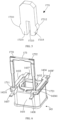
- FIG. 6 is a schematic perspective view of the coil framework and the insulation connection member in the contactor in FIG. 1 .
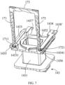
- FIG. 7 is a sectional view of the coil framework and the insulation connection member in FIG. 6 , where a cut plane passes through the two insertion ends of the insulation connection member.
- the coil framework 143 is integrally formed, and includes a framework body 1431, a first fixed portion 1433, and a second fixed portion 1434.
- the framework body 1431 is substantially in the shape of a hollow column, and has an end surface 1432 facing the movable iron core and the support member (not shown in FIG. 6 and FIG. 7 ).
- the first fixed portion 1433 and the second fixed portion 1434 are substantially in the shape of a rod, are opposite each other, and are respectively fixed on edges of the end surface 1432 of the framework body 1431.
- the first fixed portion 1433 and the second fixed portion 1434 respectively have an auxiliary hole 14331 and an auxiliary hole 14341.
- An opening of the auxiliary hole 14331 and an opening of the auxiliary hole 14341 face the electrode top plate 121, and are respectively aligned with the first expanded hole 1241 and the second expanded hole 1242 on the electrode top plate 121.
- the coil framework 143 further includes a first connecting piece 1435 and a second connecting piece 1436 made from a metal material and an electromagnetic coil (not shown in FIG. 6 and FIG. 7 ) wound on the coil framework 143.
- the first connecting piece 1435 and the first fixed portion 1433 are fixed to each other by means of an injection molding process, and two ends 1437 and 1437' of the first connecting piece 1435 extend out of two ends of the first fixed portion 1433.
- the second connecting piece 1436 and the second fixed portion 1434 are fixed to each other by means of an injection molding process, and two ends 1438 and 1438' of the second connecting piece 1436 extend out of two ends of the second fixed portion 1434.
- the end 1437 of the first connecting piece 1435 and the end 1438 of the second connecting piece 1436 are configured to be electrically connected to two connection terminals in the auxiliary wiring module 13. Two ends of the electromagnetic coil are electrically connected to the first connecting piece 1435 and the second connecting piece 1436 respectively.
- the insertion end 1711 of the first conducting element 171 and the insertion end 1721 of the second conducting element 172 respectively pass through the first expanded hole 1241 and the second expanded hole 1242 of the electrode top plate 121 (refer to FIG. 2 ), and are inserted into the auxiliary hole 14331 and the auxiliary hole 14341, so as to be electrically connected to the first connecting piece 1435 and the second connecting piece 1436.
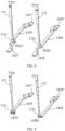
- FIG. 8 is a schematic perspective view of the first connecting piece, the second connecting piece, the first conducting element, and the second conducting element in the coil framework and the insulation connection member in FIG. 6 .
- FIG. 9 is a sectional view of the first connecting piece, the second connecting piece, the first conducting element, and the second conducting element in FIG. 8 , where a cut plane passes through the two insertion ends of the insulation connection member.
- the first connecting piece 1435 has a through-hole 14351 aligned with the auxiliary hole 14331 of the first fixed portion 1433
- the second connecting piece 1436 has a through-hole 14361 aligned with the auxiliary hole 14341 of the second fixed portion 1434.
- the two protrusions on the insertion end 1711 first contact the opening of the auxiliary hole 14331, and the auxiliary hole 14331 squeezes the two protrusions on the insertion end 1711, so that the distance between the two protrusions decreases, and therefore the insertion end 1711 can be further inserted into the through-hole 14351 of the first connecting 1435.
- the insertion end 1711 is resilient to some extent, so that the two protrusions thereon are urged against or abut an inner side wall of the through-hole 14351 of the first connecting piece 1435.
- the insertion end 1721 of the second conducting element 172 is subjected to the same deformation in an insertion process as the insertion end 1711, and details will not be described herein again. Finally, the first conducting element 171 and the second conducting element 172 well mechanically contact and are reliably electrically connected to the first connecting piece 1435 and the second connecting piece 1436 respectively.
- the pluggable connecting device 17 can be inserted into the housing 5 by means of the first expanded hole 1241 and the second expanded hole 1242 on the electrode top plate 121 until the insertion end 1711 and the insertion end 1721 in the pluggable connecting device 17 are respectively embedded in the through-hole 14351 of the first connecting piece 1435 and the through-hole 14361 of the second connecting piece 1436.
- the first conducting element 171, the first connecting piece 1435, the electromagnetic coil, the second connecting piece 1436, and the second conducting element 172 form a conducting path
- the bent portion 1713 of the first conducting element 171 and the bent portion 1723 of the second conducting element 172 serve as external connection terminals of the contactor 1.
- the two wiring terminals of the power source can be respectively connected to the bent portion 1713 of the first conducting element 171 and the bent portion 1723 of the second conducting element 172, so that wiring can be easily performed above the electrode top plate 121 of the contactor 1 so as to energize or de-energize the electromagnetic coil in the contactor 1.
- the electrical signal in the electromagnetic coil can be acquired from the bent portion 1713 of the first conducting element 171 and the bent portion 1723 of the second conducting element 172, thereby facilitating monitoring of the electrical signal in the electromagnetic coil or an on or off state of the contactor 1.
- the pluggable connecting device 17 is integrally formed, has a firm structure, and can be easily inserted into or pulled out of the contactor 1 by an operator.
- the insulation connection member 173 in the pluggable connecting device 17 is wrapped around or covers the first conducting element 171 and the second conducting element 172, thereby preventing the first conducting element 171 and the second conducting element 172 from being electrically connected to other conducting components in the limited space in the contactor 1.
- the operation connection portion 1734 is made from an insulation material, so as to be easily operated by an operator by hand.
- the recessed portion 1733 on the operation connection portion 1734 enables the operator to easily pull the pluggable connecting device 17 out of the contactor 1, and no additional component is added, thereby resulting in a simple structure and low manufacturing costs.
- the first conducting element 171 has the bent portion
- the second conducting element 172 has the bent portion, thereby enlarging a contact region or a contact area between the same and an external circuit module.
- the bent portion of the first conducting element 171 and the bent portion of the second conducting element 172 are located in the first accommodation space 1731 and the second accommodation space 1732 defined by the operation connection portion 1734, thereby avoiding electric shock hazards caused by accidentally touching the first conducting element 171 and the second conducting element 172.
- the insertion end 1711 of the first conducting element 171 has the insertion slot
- the insertion end of the second conducting element 172 has the insertion slot, so that the insertion ends 1711 and 1721 are elastically deformable and resilient to some extent. Due to the resilience, the insertion ends 1711 and 1721 can well mechanically contact the first connecting piece 1435 and the second connecting piece 1436.
- the protrusions on the insertion ends 1711 and 1721 can further improve mechanical contact and electrical connection, thereby ensuring reliable electric conductivity.
- the first conducting element 171 has the step portion
- the second conducting element 172 has the step portion, so that the contact between the injection-molded insulation connection member 173 and the first conducting element 171 and the contact between the injection-molded insulation connection member 173 and the second conducting element 172 are firmer, thereby preventing falling off.
- present utility model has been described through preferred embodiments, the present utility model is not limited to the embodiments described here, and further includes various changes and variations made without departing from the scope of the present utility model.
Landscapes
- Physics & Mathematics (AREA)
- Electromagnetism (AREA)
- Details Of Connecting Devices For Male And Female Coupling (AREA)
- Switch Cases, Indication, And Locking (AREA)
Claims (12)
- Dispositif de connexion enfichable (17) pour contacteurs (1),
le contacteur (1) comprenant :un boîtier (5) ;un cadre de bobine (143) situé dans le boîtier (5) et comportant une première partie de connexion (1435) et une seconde partie de connexion (1436) agencées pour être face à face ; etune bobine électromagnétique enroulée sur le cadre de bobine (143), deux extrémités de la bobine électromagnétique étant respectivement connectées électriquement à la première partie de connexion (1435) et à la seconde partie de connexion (1436), dans lequelle dispositif de connexion enfichable (17) comprend un élément de connexion d'isolation (173) et un premier élément conducteur (171) et un second élément conducteur (172) connectés à demeure à l'élément de connexion d'isolation (173) ; le premier élément conducteur (171) a une extrémité d'insertion (1711) et une extrémité de câblage (1712) agencées pour être face à face ; le second élément conducteur (172) a une extrémité d'insertion (1721) et une extrémité de câblage (1722) agencées pour être face à face ; l'extrémité d'insertion (1711) du premier élément conducteur (171) et l'extrémité d'insertion (1721) du second élément conducteur (172) sont agencées pour être connectées de manière enfichable respectivement à la première partie de connexion (1435) et à la seconde partie de connexion (1436) du contacteur (1) ;dans lequel l'extrémité d'insertion (1711) du premier élément conducteur (171) comporte deux premières portions de mise en prise en regard (17214, 17215) ; une fente d'insertion (17213) est définie entre les deux premières portions de mise en prise (17214, 17215) ; l'extrémité d'insertion (1721) du second élément conducteur (172) comporte deux secondes portions de mise en prise en regard (17214, 17215) ; une fente d'insertion (17213) est définie entre les deux secondes portions de mise en prise (17214, 17215) ;caractérisé en ce queles deux premières portions de mise en prise (17214, 17215) présentent chacune une saillie (17211, 17212), les saillies étant situées à l'écart l'une de l'autre, et les deux secondes portions de mise en prise (17214, 17215) présentent chacune une saillie (17211, 17212), les saillies étant situées à l'écart l'une de l'autre. - Dispositif de connexion enfichable selon la revendication 1, dans lequel le boîtier (5) du contacteur (1) comprend une plaque supérieure d'électrode et une plaque inférieure de montage (4) agencées pour être face à face ; le dispositif de connexion enfichable (17) est en forme de U ; les premier et second éléments conducteurs (171, 172) du dispositif de connexion enfichable (17) sont conçus pour être insérés perpendiculairement à la plaque supérieure d'électrode (121), et une partie du dispositif de connexion enfichable (17) est conçue pour traverser la plaque supérieure d'électrode (121) de manière à être insérée dans le boîtier (5), et le reste du dispositif de connexion enfichable (17) est conçu pour être situé à l'extérieur du boîtier (5) ou disposé sur la plaque supérieure d'électrode (121).
- Dispositif de connexion enfichable (17) selon la revendication 1, dans lequel le premier élément conducteur (171) comprend une portion étagée disposée entre son extrémité d'insertion (1711) et son extrémité de câblage (1712), et le second élément conducteur (172) comprend une portion étagée disposée entre son extrémité d'insertion (1721) et son extrémité de câblage (1722).
- Dispositif de connexion enfichable (17) selon l'une quelconque des revendications 1 à 2, dans lequel l'extrémité de câblage (1712) du premier élément conducteur (171) présente une portion courbée (1713) ; l'extrémité de câblage (1722) du second élément conducteur (172) présente une portion courbée (1723) ; la portion courbée (1713) du premier élément conducteur (171) et la portion courbée (1723) du second élément conducteur (172) s'étendent l'une vers l'autre.
- Dispositif de connexion enfichable (17) selon l'une quelconque des revendications 1 à 4, dans lequel les saillies (17211, 17212) sur les deux premières portions de mise en prise (17214, 17215) sont orientées à l'opposé l'une de l'autre et à l'écart de la fente d'insertion définie entre les deux premières portions de mise en prise (17214, 17215), et dans lequel les saillies (17211, 17212) sur les deux secondes portions de mise en prise (17214, 17215) sont orientées à l'opposé l'une de l'autre et à l'écart de la fente d'insertion définie entre les deux secondes portions de mise en prise (17214, 17215).
- Dispositif de connexion enfichable (17) selon la revendication 5, dans lequel les portions de mise en prise (17214, 17215) sont élastiquement déformables et souples.
- Dispositif de connexion enfichable (17) selon la revendication 4, dans lequel l'élément de connexion d'isolation (173) est moulé par injection et comprend une portion de connexion opérationnelle (1734) et une première portion de recouvrement (1735) et une seconde portion de recouvrement (1736) reliées à demeure à deux extrémités de la portion de connexion opérationnelle (1734), dans lequel la première portion de recouvrement (1735) recouvre le premier élément conducteur (171) et amène l'extrémité d'insertion (1711) du premier élément conducteur (171) à être visible, et la seconde portion de recouvrement (1736) recouvre le second élément conducteur (172) et amène l'extrémité d'insertion (1721) du second élément conducteur (172) à être visible.
- Dispositif de connexion enfichable (17) selon la revendication 7, dans lequel une extrémité de la portion de connexion opérationnelle (1734) définit un premier espace de logement (1731) ayant une ouverture, et l'autre extrémité définit un second espace de logement (1732) ayant une ouverture ; la portion courbée (1713) du premier élément conducteur (171) est située dans le premier espace de logement (1731) ; la portion courbée (1723) du second élément conducteur (172) est située dans le second espace de logement (1732).
- Dispositif de connexion enfichable (17) selon la revendication 7, dans lequel la portion de connexion opérationnelle (1734) présente une portion évidée (1733) en regard du boîtier (5).
- Système comprenant un contacteur (1) et le dispositif de connexion enfichable (17) selon l'une quelconque des revendications 1 à 9, le contacteur (1) comprenant :un boîtier (5), comprenant une plaque supérieure d'électrode (121) et une plaque inférieure de montage (4) agencées pour être face à face, dans lequel la plaque supérieure d'électrode (121) comporte un premier trou élargi (1241) et un second trou élargi (1242) ;un cadre de bobine (143) situé dans le boîtier (5) et comportant une première partie de connexion (1435) et une seconde partie de connexion (1436) agencées pour être face à face ;une bobine électromagnétique enroulée sur le cadre de bobine (143), deux extrémités de la bobine électromagnétique étant respectivement connectées électriquement à la première partie de connexion (1435) et à la seconde partie de connexion (1436), dans lequella première partie de connexion (1435) et la seconde partie de connexion (1436) sont conçues pour être connectées de manière enfichable à l'extrémité d'insertion (1711) du premier élément conducteur (171) et à l'extrémité d'insertion (1721) du second élément conducteur (172) du dispositif de connexion enfichable (17).
- Système selon la revendication 10, dans lequel le cadre de bobine (143) comprend un corps de cadre (1431) et une première portion fixe (1433) et une seconde portion fixe (1434) fixées sur une surface d'extrémité (1432) du corps de cadre (1431) ; la première partie de connexion (1435) et la seconde partie de connexion (1436) sont respectivement fixées dans la première portion fixe (1433) et la seconde portion fixe (1434) ; la première partie de connexion (1435) et la première portion fixe (1433) ont respectivement un premier trou traversant (14351) et un premier trou auxiliaire (14331) alignés avec le premier trou élargi (1241) ; la seconde partie de connexion (1436) et la seconde portion fixe (1434) ont respectivement un second trou traversant (14361) et un second trou auxiliaire (14331) alignés avec le second trou élargi (1242).
- Système selon la revendication 10 ou 11,dans lequel la première partie de connexion (1435) a un trou traversant (14351), la seconde partie de connexion (1436) a un trou traversant (14361) ;dans lequel la plaque supérieure d'électrode (121) comporte un premier trou élargi (1241) aligné avec le trou traversant (14351) de la première partie de connexion (1435), un second trou élargi (1242) aligné avec le trou traversant (14361) de la seconde partie de connexion (1436), et des trous traversants d'électrode (1211 - 1218) pour le passage des fils d'électrode, la plaque inférieure de montage (4) est conçue pour être montée à demeure dans une armoire ;dans lequel une partie du dispositif de connexion enfichable (17) est conçue pour passer à travers le premier trou élargi (1241) et le second trou élargi (1242) de la plaque supérieure d'électrode (121) de manière à être insérée dans le boîtier (5), et le reste du dispositif de connexion enfichable (17) est situé à l'extérieur du boîtier (5) ou disposé sur la plaque supérieure d'électrode (121) ;dans lequel les deux saillies (17211, 17212) des deux premières portions de mise en prise (17214, 17215) sont poussées contre une paroi latérale intérieure du trou traversant (14351) de la première partie de connexion (1435) ou en butée contre elle, les deux saillies (17214, 17215) des deux secondes portions de mise en prise (17214, 17215) sont poussées contre une paroi latérale intérieure du trou traversant (14361) de la seconde partie de connexion (1436) ou en butée contre elle.
Applications Claiming Priority (1)
| Application Number | Priority Date | Filing Date | Title |
|---|---|---|---|
| CN201921256955.8U CN210200638U (zh) | 2019-08-05 | 2019-08-05 | 用于接触器的可插拔连接装置及接触器 |
Publications (2)
| Publication Number | Publication Date |
|---|---|
| EP3780060A1 EP3780060A1 (fr) | 2021-02-17 |
| EP3780060B1 true EP3780060B1 (fr) | 2025-04-23 |
Family
ID=69865735
Family Applications (1)
| Application Number | Title | Priority Date | Filing Date |
|---|---|---|---|
| EP20189720.4A Active EP3780060B1 (fr) | 2019-08-05 | 2020-08-05 | Dispositif de connexion enfichable pour contacteur et contacteur |
Country Status (4)
| Country | Link |
|---|---|
| US (1) | US11615932B2 (fr) |
| EP (1) | EP3780060B1 (fr) |
| CN (1) | CN210200638U (fr) |
| ES (1) | ES3034677T3 (fr) |
Families Citing this family (3)
| Publication number | Priority date | Publication date | Assignee | Title |
|---|---|---|---|---|
| DE102021106112A1 (de) * | 2021-03-12 | 2022-09-15 | Tdk Electronics Ag | Gehäuse für elektromechanische Komponente |
| CN117238722B (zh) * | 2022-06-06 | 2026-02-03 | 上海正泰智能科技有限公司 | 电磁系统及接触器 |
| DE102024108014B4 (de) * | 2024-03-20 | 2026-02-12 | Tdk Electronics Ag | Antriebseinheit und Schaltvorrichtung |
Family Cites Families (5)
| Publication number | Priority date | Publication date | Assignee | Title |
|---|---|---|---|---|
| FR1080739A (fr) * | 1954-04-07 | 1954-12-13 | Contacteur photo-électrique perfectionné notamment pour la commande de l'éclairage | |
| CH689526A5 (de) * | 1995-03-25 | 1999-05-31 | Rockwell Automation Ag | Sockelteil eines elektromagnetischen Schaltgeraetes, insbesondere eines Schuetzes. |
| DE102004009650B3 (de) | 2004-02-27 | 2005-07-07 | Moeller Gmbh | Schaltschütz mit Anschlussmodul zum Ansteuern des Magnetantriebes |
| CN207883619U (zh) * | 2017-12-22 | 2018-09-18 | 伊顿电气有限公司 | 一种可插拔的接触器用线圈端子 |
| CN209045441U (zh) | 2018-09-27 | 2019-06-28 | 伊顿电气有限公司 | 接触器 |
-
2019
- 2019-08-05 CN CN201921256955.8U patent/CN210200638U/zh active Active
-
2020
- 2020-08-05 US US16/985,821 patent/US11615932B2/en active Active
- 2020-08-05 ES ES20189720T patent/ES3034677T3/es active Active
- 2020-08-05 EP EP20189720.4A patent/EP3780060B1/fr active Active
Also Published As
| Publication number | Publication date |
|---|---|
| CN210200638U (zh) | 2020-03-27 |
| US11615932B2 (en) | 2023-03-28 |
| EP3780060A1 (fr) | 2021-02-17 |
| US20210043405A1 (en) | 2021-02-11 |
| ES3034677T3 (en) | 2025-08-21 |
Similar Documents
| Publication | Publication Date | Title |
|---|---|---|
| EP3780060B1 (fr) | Dispositif de connexion enfichable pour contacteur et contacteur | |
| KR102783117B1 (ko) | 보조 접점을 갖는 고전압 직류 릴레이 | |
| US11417484B2 (en) | Contactor | |
| US11361923B2 (en) | Contactor | |
| EP2765587B1 (fr) | Contacteur électromagnétique | |
| CN109961985B (zh) | 一种可插拔的接触器用线圈端子及其安装方法 | |
| CN216719791U (zh) | 一种触点开关 | |
| CN216213151U (zh) | 磁保持继电器 | |
| US10468218B2 (en) | Relay with SMA wire driven mechanism | |
| CN207883619U (zh) | 一种可插拔的接触器用线圈端子 | |
| CN209282139U (zh) | 连接端子、线圈骨架组件及继电器 | |
| CN110137036A (zh) | 一种多触点式继电器 | |
| KR200441990Y1 (ko) | 전자접촉기의 도선연결장치 | |
| JP3720642B2 (ja) | スイッチ装置 | |
| CN103871787B (zh) | 电磁接触器 | |
| KR101209801B1 (ko) | 릴레이 장치 | |
| WO2022102344A1 (fr) | Dispositif de connexion et module électrique | |
| CN114093714A (zh) | 一种磁保持继电器 | |
| CN102598185A (zh) | 开关设备 | |
| CN110690064B (zh) | 一种负载开关 | |
| CN224217454U (zh) | 一种漏电保护器 | |
| CN221861531U (zh) | 继电器 | |
| CN110379679B (zh) | 带按压接线端子的小型大功率继电器 | |
| KR920007228Y1 (ko) | 전자개폐기용 전자코일의 터미널 구조 | |
| JP4091012B2 (ja) | 回路遮断器 |
Legal Events
| Date | Code | Title | Description |
|---|---|---|---|
| PUAI | Public reference made under article 153(3) epc to a published international application that has entered the european phase |
Free format text: ORIGINAL CODE: 0009012 |
|
| STAA | Information on the status of an ep patent application or granted ep patent |
Free format text: STATUS: THE APPLICATION HAS BEEN PUBLISHED |
|
| AK | Designated contracting states |
Kind code of ref document: A1 Designated state(s): AL AT BE BG CH CY CZ DE DK EE ES FI FR GB GR HR HU IE IS IT LI LT LU LV MC MK MT NL NO PL PT RO RS SE SI SK SM TR |
|
| AX | Request for extension of the european patent |
Extension state: BA ME |
|
| STAA | Information on the status of an ep patent application or granted ep patent |
Free format text: STATUS: REQUEST FOR EXAMINATION WAS MADE |
|
| 17P | Request for examination filed |
Effective date: 20210728 |
|
| RBV | Designated contracting states (corrected) |
Designated state(s): AL AT BE BG CH CY CZ DE DK EE ES FI FR GB GR HR HU IE IS IT LI LT LU LV MC MK MT NL NO PL PT RO RS SE SI SK SM TR |
|
| STAA | Information on the status of an ep patent application or granted ep patent |
Free format text: STATUS: EXAMINATION IS IN PROGRESS |
|
| 17Q | First examination report despatched |
Effective date: 20221223 |
|
| P01 | Opt-out of the competence of the unified patent court (upc) registered |
Effective date: 20230521 |
|
| GRAP | Despatch of communication of intention to grant a patent |
Free format text: ORIGINAL CODE: EPIDOSNIGR1 |
|
| STAA | Information on the status of an ep patent application or granted ep patent |
Free format text: STATUS: GRANT OF PATENT IS INTENDED |
|
| INTG | Intention to grant announced |
Effective date: 20241120 |
|
| GRAS | Grant fee paid |
Free format text: ORIGINAL CODE: EPIDOSNIGR3 |
|
| GRAA | (expected) grant |
Free format text: ORIGINAL CODE: 0009210 |
|
| STAA | Information on the status of an ep patent application or granted ep patent |
Free format text: STATUS: THE PATENT HAS BEEN GRANTED |
|
| AK | Designated contracting states |
Kind code of ref document: B1 Designated state(s): AL AT BE BG CH CY CZ DE DK EE ES FI FR GB GR HR HU IE IS IT LI LT LU LV MC MK MT NL NO PL PT RO RS SE SI SK SM TR |
|
| REG | Reference to a national code |
Ref country code: GB Ref legal event code: FG4D |
|
| REG | Reference to a national code |
Ref country code: CH Ref legal event code: EP |
|
| REG | Reference to a national code |
Ref country code: DE Ref legal event code: R096 Ref document number: 602020049840 Country of ref document: DE |
|
| REG | Reference to a national code |
Ref country code: IE Ref legal event code: FG4D |
|
| REG | Reference to a national code |
Ref country code: ES Ref legal event code: FG2A Ref document number: 3034677 Country of ref document: ES Kind code of ref document: T3 Effective date: 20250821 |
|
| REG | Reference to a national code |
Ref country code: NL Ref legal event code: MP Effective date: 20250423 |
|
| PG25 | Lapsed in a contracting state [announced via postgrant information from national office to epo] |
Ref country code: NL Free format text: LAPSE BECAUSE OF FAILURE TO SUBMIT A TRANSLATION OF THE DESCRIPTION OR TO PAY THE FEE WITHIN THE PRESCRIBED TIME-LIMIT Effective date: 20250423 |
|
| REG | Reference to a national code |
Ref country code: AT Ref legal event code: MK05 Ref document number: 1788651 Country of ref document: AT Kind code of ref document: T Effective date: 20250423 |
|
| PG25 | Lapsed in a contracting state [announced via postgrant information from national office to epo] |
Ref country code: PT Free format text: LAPSE BECAUSE OF FAILURE TO SUBMIT A TRANSLATION OF THE DESCRIPTION OR TO PAY THE FEE WITHIN THE PRESCRIBED TIME-LIMIT Effective date: 20250825 Ref country code: FI Free format text: LAPSE BECAUSE OF FAILURE TO SUBMIT A TRANSLATION OF THE DESCRIPTION OR TO PAY THE FEE WITHIN THE PRESCRIBED TIME-LIMIT Effective date: 20250423 |
|
| PGFP | Annual fee paid to national office [announced via postgrant information from national office to epo] |
Ref country code: ES Payment date: 20250901 Year of fee payment: 6 |
|
| PGFP | Annual fee paid to national office [announced via postgrant information from national office to epo] |
Ref country code: DE Payment date: 20250724 Year of fee payment: 6 |
|
| REG | Reference to a national code |
Ref country code: LT Ref legal event code: MG9D |
|
| PG25 | Lapsed in a contracting state [announced via postgrant information from national office to epo] |
Ref country code: GR Free format text: LAPSE BECAUSE OF FAILURE TO SUBMIT A TRANSLATION OF THE DESCRIPTION OR TO PAY THE FEE WITHIN THE PRESCRIBED TIME-LIMIT Effective date: 20250724 Ref country code: NO Free format text: LAPSE BECAUSE OF FAILURE TO SUBMIT A TRANSLATION OF THE DESCRIPTION OR TO PAY THE FEE WITHIN THE PRESCRIBED TIME-LIMIT Effective date: 20250723 |
|
| PG25 | Lapsed in a contracting state [announced via postgrant information from national office to epo] |
Ref country code: PL Free format text: LAPSE BECAUSE OF FAILURE TO SUBMIT A TRANSLATION OF THE DESCRIPTION OR TO PAY THE FEE WITHIN THE PRESCRIBED TIME-LIMIT Effective date: 20250423 |
|
| PGFP | Annual fee paid to national office [announced via postgrant information from national office to epo] |
Ref country code: IT Payment date: 20250723 Year of fee payment: 6 |
|
| PG25 | Lapsed in a contracting state [announced via postgrant information from national office to epo] |
Ref country code: BG Free format text: LAPSE BECAUSE OF FAILURE TO SUBMIT A TRANSLATION OF THE DESCRIPTION OR TO PAY THE FEE WITHIN THE PRESCRIBED TIME-LIMIT Effective date: 20250423 |
|
| PGFP | Annual fee paid to national office [announced via postgrant information from national office to epo] |
Ref country code: GB Payment date: 20250725 Year of fee payment: 6 |
|
| PG25 | Lapsed in a contracting state [announced via postgrant information from national office to epo] |
Ref country code: HR Free format text: LAPSE BECAUSE OF FAILURE TO SUBMIT A TRANSLATION OF THE DESCRIPTION OR TO PAY THE FEE WITHIN THE PRESCRIBED TIME-LIMIT Effective date: 20250423 |
|
| PG25 | Lapsed in a contracting state [announced via postgrant information from national office to epo] |
Ref country code: AT Free format text: LAPSE BECAUSE OF FAILURE TO SUBMIT A TRANSLATION OF THE DESCRIPTION OR TO PAY THE FEE WITHIN THE PRESCRIBED TIME-LIMIT Effective date: 20250423 |
|
| PGFP | Annual fee paid to national office [announced via postgrant information from national office to epo] |
Ref country code: FR Payment date: 20250725 Year of fee payment: 6 |
|
| PG25 | Lapsed in a contracting state [announced via postgrant information from national office to epo] |
Ref country code: RS Free format text: LAPSE BECAUSE OF FAILURE TO SUBMIT A TRANSLATION OF THE DESCRIPTION OR TO PAY THE FEE WITHIN THE PRESCRIBED TIME-LIMIT Effective date: 20250723 |
|
| PG25 | Lapsed in a contracting state [announced via postgrant information from national office to epo] |
Ref country code: IS Free format text: LAPSE BECAUSE OF FAILURE TO SUBMIT A TRANSLATION OF THE DESCRIPTION OR TO PAY THE FEE WITHIN THE PRESCRIBED TIME-LIMIT Effective date: 20250823 |
|
| PG25 | Lapsed in a contracting state [announced via postgrant information from national office to epo] |
Ref country code: LV Free format text: LAPSE BECAUSE OF FAILURE TO SUBMIT A TRANSLATION OF THE DESCRIPTION OR TO PAY THE FEE WITHIN THE PRESCRIBED TIME-LIMIT Effective date: 20250423 |
|
| PG25 | Lapsed in a contracting state [announced via postgrant information from national office to epo] |
Ref country code: DK Free format text: LAPSE BECAUSE OF FAILURE TO SUBMIT A TRANSLATION OF THE DESCRIPTION OR TO PAY THE FEE WITHIN THE PRESCRIBED TIME-LIMIT Effective date: 20250423 Ref country code: SM Free format text: LAPSE BECAUSE OF FAILURE TO SUBMIT A TRANSLATION OF THE DESCRIPTION OR TO PAY THE FEE WITHIN THE PRESCRIBED TIME-LIMIT Effective date: 20250423 |
|
| PG25 | Lapsed in a contracting state [announced via postgrant information from national office to epo] |
Ref country code: CZ Free format text: LAPSE BECAUSE OF FAILURE TO SUBMIT A TRANSLATION OF THE DESCRIPTION OR TO PAY THE FEE WITHIN THE PRESCRIBED TIME-LIMIT Effective date: 20250423 |
|
| PG25 | Lapsed in a contracting state [announced via postgrant information from national office to epo] |
Ref country code: EE Free format text: LAPSE BECAUSE OF FAILURE TO SUBMIT A TRANSLATION OF THE DESCRIPTION OR TO PAY THE FEE WITHIN THE PRESCRIBED TIME-LIMIT Effective date: 20250423 |
|
| REG | Reference to a national code |
Ref country code: DE Ref legal event code: R097 Ref document number: 602020049840 Country of ref document: DE |
|
| PG25 | Lapsed in a contracting state [announced via postgrant information from national office to epo] |
Ref country code: SK Free format text: LAPSE BECAUSE OF FAILURE TO SUBMIT A TRANSLATION OF THE DESCRIPTION OR TO PAY THE FEE WITHIN THE PRESCRIBED TIME-LIMIT Effective date: 20250423 Ref country code: RO Free format text: LAPSE BECAUSE OF FAILURE TO SUBMIT A TRANSLATION OF THE DESCRIPTION OR TO PAY THE FEE WITHIN THE PRESCRIBED TIME-LIMIT Effective date: 20250423 |
|
| PLBE | No opposition filed within time limit |
Free format text: ORIGINAL CODE: 0009261 |
|
| STAA | Information on the status of an ep patent application or granted ep patent |
Free format text: STATUS: NO OPPOSITION FILED WITHIN TIME LIMIT |
|
| REG | Reference to a national code |
Ref country code: CH Ref legal event code: L10 Free format text: ST27 STATUS EVENT CODE: U-0-0-L10-L00 (AS PROVIDED BY THE NATIONAL OFFICE) Effective date: 20260304 |
|
| REG | Reference to a national code |
Ref country code: CH Ref legal event code: H13 Free format text: ST27 STATUS EVENT CODE: U-0-0-H10-H13 (AS PROVIDED BY THE NATIONAL OFFICE) Effective date: 20260324 |
|
| PG25 | Lapsed in a contracting state [announced via postgrant information from national office to epo] |
Ref country code: MC Free format text: LAPSE BECAUSE OF FAILURE TO SUBMIT A TRANSLATION OF THE DESCRIPTION OR TO PAY THE FEE WITHIN THE PRESCRIBED TIME-LIMIT Effective date: 20250423 |
|
| 26N | No opposition filed |
Effective date: 20260126 |
|
| PG25 | Lapsed in a contracting state [announced via postgrant information from national office to epo] |
Ref country code: LU Free format text: LAPSE BECAUSE OF NON-PAYMENT OF DUE FEES Effective date: 20250805 |
|
| PG25 | Lapsed in a contracting state [announced via postgrant information from national office to epo] |
Ref country code: CH Free format text: LAPSE BECAUSE OF NON-PAYMENT OF DUE FEES Effective date: 20250831 |