EP3780260B1 - Appareil d'antenne à entrées multiples et sorties multiples - Google Patents
Appareil d'antenne à entrées multiples et sorties multiples Download PDFInfo
- Publication number
- EP3780260B1 EP3780260B1 EP19785289.0A EP19785289A EP3780260B1 EP 3780260 B1 EP3780260 B1 EP 3780260B1 EP 19785289 A EP19785289 A EP 19785289A EP 3780260 B1 EP3780260 B1 EP 3780260B1
- Authority
- EP
- European Patent Office
- Prior art keywords
- heat radiation
- heat
- transmitting
- generation elements
- antenna apparatus
- Prior art date
- Legal status (The legal status is an assumption and is not a legal conclusion. Google has not performed a legal analysis and makes no representation as to the accuracy of the status listed.)
- Active
Links
Images


Classifications
-
- H—ELECTRICITY
- H01—ELECTRIC ELEMENTS
- H01Q—ANTENNAS, i.e. RADIO AERIALS
- H01Q21/00—Antenna arrays or systems
- H01Q21/0006—Particular feeding systems
- H01Q21/0025—Modular arrays
-
- H—ELECTRICITY
- H05—ELECTRIC TECHNIQUES NOT OTHERWISE PROVIDED FOR
- H05K—PRINTED CIRCUITS; CASINGS OR CONSTRUCTIONAL DETAILS OF ELECTRIC APPARATUS; MANUFACTURE OF ASSEMBLAGES OF ELECTRICAL COMPONENTS
- H05K1/00—Printed circuits
- H05K1/02—Details
- H05K1/0201—Thermal arrangements, e.g. for cooling, heating or preventing overheating
- H05K1/0203—Cooling of mounted components
- H05K1/0204—Cooling of mounted components using means for thermal conduction connection in the thickness direction of the substrate
-
- H—ELECTRICITY
- H01—ELECTRIC ELEMENTS
- H01Q—ANTENNAS, i.e. RADIO AERIALS
- H01Q1/00—Details of, or arrangements associated with, antennas
- H01Q1/02—Arrangements for de-icing; Arrangements for drying-out ; Arrangements for cooling; Arrangements for preventing corrosion
-
- H—ELECTRICITY
- H01—ELECTRIC ELEMENTS
- H01Q—ANTENNAS, i.e. RADIO AERIALS
- H01Q1/00—Details of, or arrangements associated with, antennas
- H01Q1/36—Structural form of radiating elements, e.g. cone, spiral, umbrella; Particular materials used therewith
- H01Q1/38—Structural form of radiating elements, e.g. cone, spiral, umbrella; Particular materials used therewith formed by a conductive layer on an insulating support
-
- H—ELECTRICITY
- H01—ELECTRIC ELEMENTS
- H01Q—ANTENNAS, i.e. RADIO AERIALS
- H01Q1/00—Details of, or arrangements associated with, antennas
- H01Q1/42—Housings not intimately mechanically associated with radiating elements, e.g. radome
-
- H—ELECTRICITY
- H01—ELECTRIC ELEMENTS
- H01Q—ANTENNAS, i.e. RADIO AERIALS
- H01Q21/00—Antenna arrays or systems
-
- H—ELECTRICITY
- H04—ELECTRIC COMMUNICATION TECHNIQUE
- H04B—TRANSMISSION
- H04B1/00—Details of transmission systems, not covered by a single one of groups H04B3/00 - H04B13/00; Details of transmission systems not characterised by the medium used for transmission
- H04B1/38—Transceivers, i.e. devices in which transmitter and receiver form a structural unit and in which at least one part is used for functions of transmitting and receiving
- H04B1/40—Circuits
-
- H—ELECTRICITY
- H05—ELECTRIC TECHNIQUES NOT OTHERWISE PROVIDED FOR
- H05K—PRINTED CIRCUITS; CASINGS OR CONSTRUCTIONAL DETAILS OF ELECTRIC APPARATUS; MANUFACTURE OF ASSEMBLAGES OF ELECTRICAL COMPONENTS
- H05K7/00—Constructional details common to different types of electric apparatus
- H05K7/20—Modifications to facilitate cooling, ventilating, or heating
- H05K7/2039—Modifications to facilitate cooling, ventilating, or heating characterised by the heat transfer by conduction from the heat generating element to a dissipating body
- H05K7/20409—Outer radiating structures on heat dissipating housings, e.g. fins integrated with the housing
-
- H—ELECTRICITY
- H05—ELECTRIC TECHNIQUES NOT OTHERWISE PROVIDED FOR
- H05K—PRINTED CIRCUITS; CASINGS OR CONSTRUCTIONAL DETAILS OF ELECTRIC APPARATUS; MANUFACTURE OF ASSEMBLAGES OF ELECTRICAL COMPONENTS
- H05K2201/00—Indexing scheme relating to printed circuits covered by H05K1/00
- H05K2201/10—Details of components or other objects attached to or integrated in a printed circuit board
- H05K2201/10007—Types of components
- H05K2201/10098—Components for radio transmission, e.g. radio frequency identification [RFID] tag, printed or non-printed antennas
Definitions
- the present disclosure relates to a multi input and multi output antenna apparatus, and more particularly, to a multi input and multi output antenna apparatus for wireless communication.
- a wireless communication technology for example, the MIMO (Multiple Input Multiple Output) technology refers to a spatial multiplexing technique which significantly increases a data transfer capacity using a plurality of antennas, and in which transmitters transmits different data through transmitting antennas thereof, respectively, and receivers sort the transmitted data through proper signal processing.
- MIMO Multiple Input Multiple Output
- a channel capacity can be increased to transmit more data. For example, when the number of antennas is increased to 10, it is possible to secure a channel capacity ten times larger than in the current single antenna system, using the same frequency band.
- the 4G LTE-advanced uses eight antennas, and a product having 64 or 128 antennas mounted thereon is developed in the current pre-5G era. Also, it is expected that base station equipment with a much larger number of antennas will be used in the 5G era.
- This technology is referred to as massive MIMO technology.
- massive MIMO technology Currently, the cell operation is performed in a 2-dimension manner. However, when the massive MIMO technology is introduced, 3D-beamforming becomes possible. Thus, the massive MIMO is also referred to as FD (Full Dimension)-MIMO.
- RF parts (antenna/filter/power amplifier/transceiver etc.) need to be reduced in size and weight and manufactured at low prices, and the massive MIMO requires high power for coverage expansion. Power consumption and heat generation caused by such high power serve as negative factors in reducing the weights and sizes of the RF parts.
- WO 2018/043999 A1 discloses an antenna apparatus which comprises an array antenna formed on a metal case of an electronic device, wherein the array antenna comprises at least two antenna elements, the at least two antenna elements may operate in the same frequency band. According to one embodiment of the present invention, it is possible to provide an antenna apparatus capable of reducing heat generation and increasing the radiation efficiency of an antenna.
- WO 2017/086377 A1 describes a wireless communication device with a reflection plate having a reflective surface that reflects electromagnetic waves, an array antenna having a plurality of antenna elements that are arranged on the reflective surface, one or more fins which stand on the reflective surface, and a transmission/reception circuit which is connected to the reflection plate and transmits/receives a radio signal via the array antenna.
- Various embodiments are directed to a multi input and multi output antenna apparatus capable of implementing high power and having an excellent heat radiation characteristic.
- heat generation elements which generate a large amount of heat may be selectively concentrated to have more efficient heat radiation performance to the outside, and a product may be reduced in size, which makes it easy to additionally install a 5G multi input and multi output antenna apparatus.
- FIGS. 1 and 2 are perspective views illustrating front and rear parts of a multi input and multi output antenna apparatus in accordance with an embodiment of the present disclosure
- FIGS. 3 and 4 are front and rear exploded perspective views illustrating the front and rear parts of the multi input and multi output antenna apparatus of FIGS. 1 and 2 .
- a multi input and multi output antenna apparatus 1 in accordance with the embodiment of the present disclosure may receive power from a power supply module (not illustrated), and wirelessly communicate with an external terminal and base stations through a wireless transmitting/receiving module embedded therein.
- the multi input and multi output antenna apparatus 1 in accordance with the embodiment of the present disclosure is related to a MIMO (Multi Input Multi Output) wireless communication antenna system.
- MIMO Multi Input Multi Output
- the multi input and multi output antenna apparatus 1 in accordance with the embodiment of the present disclosure includes an antenna board 11 and a transmitting/receiving module board 110.
- the antenna board 11 includes a plurality of antenna elements 13 arranged on a front surface thereof
- the transmitting/receiving module board 110 includes a plurality of first heat generation elements arranged on a front surface thereof and a plurality of second heat generation elements arranged on a rear surface thereof, and is disposed to have a separation space from the antenna board 11.
- the first and second heat generation elements are electrically driven to generate heat.
- the direction in which an antenna installation pillar to be described below is provided is defined as 'rear'
- the direction in which a radome 5 is provided is defined as 'front', in order to prevent confusion about understandings of the present disclosure.
- the directions will be defined and described. However, this is only in order to prevent confusion of convenience of description and understandings of the present disclosure, and the scope of the present disclosure is not limited thereto.
- the antenna board 11 is housed in an antenna housing 10, such that the antenna elements 13 installed on the antenna board 11 are exposed to the front.
- the communication parts mounted on the antenna board 11 may include not only the plurality of antenna elements 13 but also an MBF (Multi-Band Filter).
- the radome 5 may be disposed at the front of the antenna board 11 so as to cover the antenna board 11.
- the radome 5 may be formed of a material which wireless signals transmitted from or to the antenna elements 13 penetrate.
- the radome 5 may be formed of insulating plastic.
- the radome 5 is provided at the front of the multi input and multi output antenna apparatus 1.
- the radome 5 and the antenna housing 10 may have almost the same size. Specifically, the radome 5 and the antenna housing 10 may be formed at a ratio compared to the antenna board 11 housed in the antenna housing 10. Desirably, in the multi input and multi output antenna apparatus 1 in accordance with the embodiment of the present disclosure, the antenna board 11 may be formed in a rectangular shape having a horizontal length larger than a vertical length thereof, in order to remove installation interference with another antenna apparatus 1, which is already installed or is to be installed later, when the multi input and multi output antenna apparatus 1 is installed on the antenna installation pillar which will be additionally described below in 5G.
- the multi input and multi output antenna apparatus 1 in accordance with the embodiment of the present disclosure includes an antenna assembly in which modules having the RF elements and the digital elements implemented therein are coupled through a stacked structure.
- Main modules of the antenna assembly may be divided into three layers.
- the antenna board 11 serving as a first layer may be a PCB (Printed Circuit Board) on which a calibration network is implemented, and have the plurality of antenna elements 13 disposed on a front surface thereof and the plurality of MBFs mounted on a rear surface thereof.
- PCB Print Circuit Board
- the transmitting/receiving module board 110 serving as a second layer may be coupled to the first layer so as to have the above-described separation space therebetween.
- the transmitting/receiving module board 110 may have a plurality of RFICs 125 mounted on the front surface thereof and connected to the plurality of antenna elements 13.
- the plurality of communication parts including the plurality of RFICs 125, which are heat generation elements to generate a predetermined amount of heat when electrically operated, may be defined as 'a plurality of first heat generation elements' .
- the transmitting/receiving module board 110 may include a plurality of FPGAs 115 mounted on the rear surface thereof, the plurality of FPGAs 115 performing a digital signal processing operation of receiving a converted digital signal from an analog/digital converter, and converting the received signal into a base band signal.
- the transmitting/receiving module board 110 includes analog processing circuits such as PAs (Power Amplifier), implemented on the rear surface thereof.
- PAs included in the analog processing circuit may be electrically connected to the above-described MBFs through an RF interface.
- a digital processing circuit may be implemented on the rear surface of the transmitting/receiving module board 110, and a PSU (Power Supply Unit) may be mounted on the rear surface of the transmitting/receiving module board 110.
- the digital processing circuit performs a function of converting a digital signal received from a base station BBU (Base Band Unit) into an analog RF signal, and converting an analog RF signal received from an antenna into a digital signal and transmitting the digital signal to the base station BBU.
- BBU Base Band Unit
- the plurality of FPGAs 115 and the PSU are heat generation elements to generate a predetermined amount of heat when electrically operated, like the plurality of first heat generation elements.
- the plurality of FPGAs 115 and the PSU may be defined as 'a plurality of second heat generation elements'.
- the antenna board 11 is designed in such a shape that the top-to-bottom width thereof is reduced.
- an additional antenna apparatus 1 may be easily installed in 5G.
- various communication parts integrated on the transmitting/receiving module board 110 are distributed and disposed on the front and rear surfaces thereof, in order to easily radiate heat.
- heat generated from the first heat generation elements provided on the front surface of the transmitting/receiving module board 110 is radiated to the front of the transmitting/receiving module board 110
- heat generated from the second heat generation elements provided on the rear surface of the transmitting/receiving module board 110 is radiated to the rear of the transmitting/receiving module board 110.
- the antenna board 11 and the transmitting/receiving module board 110 may be disposed with the predetermined separation space provided therebetween, in order to minimize the influence of the heat, generated from the first heat generation elements on the front surface of the transmitting/receiving module board 110, on the antenna elements 13 disposed in front of the transmitting/receiving module board 110.
- the heat generated from the first heat generation elements may be radiated to the separation space.
- FIGS. 5A and 5B are front and rear exploded perspective views illustrating a one-side heat radiation unit and the other-side heat radiation unit among components of the multi input and multi output antenna apparatus in accordance with the embodiment of the present disclosure
- FIG. 6 is a cross-sectional view taken along line A-A of FIG. 1
- FIG. 7 is a cross-sectional view taken along line B-B of FIG. 1
- FIG. 8 is a cross-sectional view taken along line C-C of FIG. 1 .
- the antenna board 11 and the transmitting/receiving module board 110 may be divided by a front heat radiation unit 20 disposed in the separation space, as illustrated in FIGS. 5A and 5B .
- the front heat radiation unit 20 may be formed of a metallic material.
- the front heat radiation unit 20 is formed of a metallic material, it is possible to minimize the influence of electromagnetic waves between the plurality of communication parts provided on the transmitting/receiving module board 110 and the plurality of antenna elements 13 disposed on the antenna board 11 in front of the transmitting/receiving module board 110.
- a rear heat radiation unit 30 may be disposed outside the transmitting/receiving module board 110 so as to cover the transmitting/receiving module board 110, as illustrated in FIGS. 5A and 5B . Therefore, the front heat radiation unit 20 may be disposed in contact with the first heat generation elements provided on the front surface of the transmitting/receiving module board 110, and the rear heat radiation unit 30 may be disposed in contact with the second heat generation elements provided on the rear surface of the transmitting/receiving module board 110.
- the front heat radiation unit 20 may be disposed in the separation space.
- the front heat radiation unit 20 may be disposed in the separation space so as to fill the separation space between the antenna board 11 and the transmitting/receiving module board 110.
- the introduction of external air which may take part in heat radiation of the front heat radiation unit 20, may be blocked to reduce the heat radiation performance.
- the front end of the front heat radiation unit 20 and the antenna housing 10 in which the antenna board 11 is housed may be spaced to some extent apart from each other.
- the rear heat radiation unit 30 may be disposed in an outer space around the transmitting/receiving module board 110, facing the separation space. That is, the rear heat radiation unit 30 may be disposed to completely cover the other surface of the transmitting/receiving module board 110.
- the front heat radiation unit 20 may include a front heat radiation body 21 and a plurality of front unit heat radiation bodies 40.
- the front heat radiation body 21 may be disposed in contact with the front surface of the transmitting/receiving module board 110 and include a plurality of main heat radiation pins 23 protruding to the front thereof.
- the plurality of front unit heat radiation bodies 40 may be disposed through the front heat radiation body 21, and have one ends contacted with at least some of the first heat generation elements of the transmitting/receiving module board 110 and the other ends on which a plurality of sub heat radiation pins 43 for radiating heat conducted from the first heat radiation elements to the outside are provided.
- the main heat radiation pins' provided on the front heat radiation body 21 are referred to as the front main heat radiation pins 23'
- 'the sub heat radiation pins' provided on the front unit heat radiation body 40 are referred to as 'the front sub heat radiation pins 43', in order to distinguish the heat radiation pins from components of the rear heat radiation unit 30, which will be described below.
- the plurality of front main heat radiation pins 23 serve to radiate heat transferred from the first heat generation elements to the front heat radiation body 21 by exchanging the heat with external air introduced from the outside. Therefore, the front heat radiation body 21 may be formed of a metallic material which easily conducts heat, and the plurality of front main heat radiation pins 23 may also be formed of a metallic material which can easily conducts heat.
- the plurality of front main heat radiation pins 23 may be formed on the front surface of the front heat radiation body 21.
- the plurality of front main heat radiation pins 23 may be formed as one body with the front heat radiation body 21.
- the present disclosure is not limited thereto, and the plurality of front main heat radiation pins 23 may be manufactured as separate members, and bonded to the front surface of the front heat radiation body 21 through a thermally conductive adhesive, or fixed through a separate fastening member such as a bolt.
- the plurality of front unit heat radiation bodies 40 serve to radiate heat to the above-described separation space, separately from the front heat radiation body 21 which radiates heat generated from the RFICs 125 connected to the plurality of first heat generation elements, or specifically the plurality of antenna elements 13 which will be described below.
- the multi input and multi output antenna apparatus 1 in accordance with the embodiment of the present disclosure adopts a structure that separately radiates heat generated from the RFICs 125 among the communication parts which generate a large amount of heat among the first heat generation elements.
- the heat generated from the plurality of RFICs 125 may be more quickly radiated.
- the plurality of front main heat radiation pins 23 formed on the front surface of the front heat radiation body 21 may be disposed so as to be inclined upward. That is, as the multi input and multi output antenna apparatus 1 in accordance with the embodiment of the present disclosure is disposed in the top-to-bottom direction in FIGS. 5A and 5B , the plurality of front main heat radiation pins 23 may be formed to have an air flow path in the top-to-bottom direction, such that external air is easily introduced into the separation space. Furthermore, in the multi input and multi output antenna apparatus 1 in accordance with the embodiment of the present disclosure, the plurality of front main heat radiation pins 23 are inclined upward to further increase the amount of external air introduced into the separation space. Thus, the external air may be easily introduced through the side portions as well as the bottom portion of the front heat radiation body 21.
- the plurality of front main heat radiation pins 23 may include a left heat radiation pin part inclined upward toward the top-to-bottom center line of the front heat radiation body 21 from the left side in FIG. 5A , and a right heat radiation pin part inclined upward toward the top-to-bottom center line of the front heat radiation body 21 from the right side in FIG. 5A .
- the plurality of front main heat radiation pins 23 may be divided into two groups, i.e. the left heat radiation pin part and the right heat radiation pin part, such that the external air is introduced through the left heat radiation pin part from the left side of the front heat radiation body 21 and flows upward toward the middle of the front surface of the front heat radiation body 21, and the external air is introduced through the right heat radiation pin part from the right side of the front heat radiation body 21 and flows upward toward the middle of the front surface of the front heat radiation body 21.
- the heat-exchanged air gathering in the middle of the front surface of the front heat radiation body 21 from both sides thereof may be discharged upward to the space between the left heat radiation pin part and the right heat radiation pin part.
- one ends of the plurality of front unit heat radiation bodies 40 may be fixed to the front heat radiation body 21, and the other ends of the plurality of front unit heat radiation bodies 40 may be fixed to the rear surface of the antenna housing 10 in which the antenna board 11 is housed.
- each of the front unit heat radiation bodies 40 may include a coupling part 41, a conduction part 42 and the plurality of sub heat radiation pins 43.
- the coupling part 41 serving as the one end is coupled to the front heat radiation body 21 so as to be contacted with any one of the first heat generation elements, the conduction part 42 transfers heat, conducted through the coupling part 41, to the separation space, and the plurality of sub heat radiation pins 43 are stacked on the outer circumference of the conduction part 42 so as to be spaced part from each other.
- the leading end of the conduction part 42, serving as the other end, may be fixed to the rear surface of the antenna housing 10.
- the plurality of front sub heat radiation pins 43 may have the same heat radiation area. This is because, since some of the plurality of front sub heat radiation pins 43 may be disposed to cover or overlap the plurality of front main heat radiation pins 23 when the front sub heat radiation pins 43 have different heat radiation areas, the heat radiation performance is not significantly increased.
- the plurality of front sub heat radiation pins 43 of the front unit heat radiation bodies 40 may be exposed to the separation space. That is, the front-to-rear lengths of the plurality of front unit heat radiation bodies 40 may be set to such a value that the one ends of the front unit heat radiation bodies 40 are coupled to the front heat radiation body 21 and the other ends of the front unit heat radiation bodies 40 further protrude to the separation space than the plurality of front main heat radiation pins 23 formed on the front heat radiation body 21. As parts of the plurality of front unit heat radiation bodies 40 are exposed to the separation space between ends of the plurality of front main heat radiation pins 23 and the antenna housing 10, heat may be more quickly radiated.
- the front heat radiation body 21 may have coupling holes (not illustrated) to which the coupling parts 41 of the front unit heat radiation bodies 40 are coupled.
- the coupling parts 41 of the plurality of front unit heat radiation bodies 40 may be disposed in contact with a heat generation surface of at least any one of the first heat generation elements through the coupling holes 37 of the front heat radiation bodies 21. At this time, the coupling part 41 may be coupled to the coupling hole through a screwing method.
- the coupling between the front heat radiation body 21 and the front unit heat radiation bodies 40 is not limited to the screwing method. That is, although not illustrated, the plurality of front unit heat radiation bodies 40 may be coupled through a simple rotation coupling method in which the coupling parts 41 of the plurality of front unit heat radiation bodies 40 have male screw threads formed on outer circumferential surfaces thereof and the coupling holes 37 of the front heat radiation bodies 21 have female screw threads formed on inner circumferential surfaces thereof, as long as the plurality of front unit heat radiation bodies 40 are coupled so as to be contacted with the heat generation surfaces of the first heat generation elements.
- FIGS. 9A and 9B are front and rear exploded perspective views illustrating a BB board and a heat radiation structure thereof, among the components of the multi input and multi output antenna apparatus in accordance with the embodiment of the present disclosure
- FIG. 10 is a cross-sectional view taken along D-D line in the state of FIG. 9A , including an expanded view of a portion of the BB board.
- the rear surface of the transmitting/receiving module board 110 may be covered by the rear heat radiation unit 30, as illustrated in FIGS. 5A and 5B . That is, the rear heat radiation unit 30 serves to protect the transmitting/receiving module board 110 from external pollutants by shielding the rear surface of the transmitting/receiving module board 110.
- the rear heat radiation unit 30 may be formed of a metallic material having excellent heat conductivity.
- the material of the rear heat radiation unit 30 is not particularly limited as long as the material has excellent heat conductivity.
- the transmitting/receiving module board 110 may be provided so that heat generated from the first heat generation elements provided on the front surface thereof is radiated to the separation space by the front heat radiation unit 20, and heat generated from the second heat generation elements provided on the rear surface thereof is radiated to the outer space by the rear heat radiation unit 30.
- the rear heat radiation unit 30 may include a rear heat radiation body 31 and a plurality of rear unit heat radiation bodies 50.
- the rear heat radiation body 31 may be disposed in contact with the rear surface of the transmitting/receiving module board 110, and have a plurality of main heat radiation pins protruding to the rear thereof, and the plurality of rear unit heat radiation bodies 50 may be disposed through the rear heat radiation body 31, and have one ends contacted with at least some of the second heat generation elements of the transmitting/receiving module board 110 and the other ends on which a plurality of sub heat radiation pins for radiating heat conducted from the second heat generation elements to the outside are provided.
- the plurality of main heat radiation pins are referred to as 'rear main heat radiation pins 33' in order to distinguish from 'the front main heat radiation pins' of the front heat radiation unit 20, and the plurality of sub heat radiation pins are referred to as 'rear sub heat radiation pins 53' in order to distinguish from 'the front sub heat radiation pins 43' of the front heat radiation unit 20.
- the plurality of rear main heat radiation pins 33 serve to radiate heat, transferred from the second heat generation elements to the rear heat radiation body 31, by exchanging the heat with external air. Therefore, like the front heat radiation body 21, the rear heat radiation body 31 may be formed of a metallic material which easily conducts heat, and the plurality of rear main heat radiation pins 33 may also be formed of a metallic material which easily conducts heat.
- the plurality of rear main heat radiation pins 33 may be formed on the rear surface of the rear heat radiation body 31.
- the plurality of rear main heat radiation pins 33 may be formed as one body with the rear heat radiation body 31, or manufactured as separate members and bonded to the rear surface of the rear heat radiation body 31 through a thermally conductive adhesive or fixed through a separate fastening member such as a bolt.
- the plurality of rear unit heat radiation bodies 50 serve to radiate heat from the plurality of second heat generation elements to the outer space, separately from the rear heat radiation body 31.
- the multi input and multi output antenna apparatus 1 in accordance with the embodiment of the present disclosure adopts a structure which separately radiates heat generated from the plurality of FPGAs 115 among the communication parts which generate a large amount of heat among the second heat generation elements.
- the plurality of FPGAs 115 serve to perform a digital signal processing operation of receiving a converted digital signal from an analog/digital converter, and converting the received signal into a base band signal.
- heat generated from the plurality of RFICs 125 which generates a relatively large amount of heat, may be more quickly radiated.
- the plurality of rear main heat radiation pins 33 formed on the rear surface of the rear heat radiation body 31 may be disposed so as to be inclined upward, like the plurality of front main heat radiation pins 23.
- the plurality of rear main heat radiation pins 33 may be inclined upward to further increase the amount of external air introduced into the plurality of rear main heat radiation pins 33. Therefore, the external air may be easily introduced through the side portions as well as the bottom portion of the rear heat radiation body 31.
- the plurality of rear main heat radiation pins 33 may include a left heat radiation pin part 34 inclined upward toward the top-to-bottom center line of the rear heat radiation body 31 from the left side of FIG. 5B , and a right heat radiation pin part 35 inclined upward toward the top-to-bottom center line of the rear heat radiation body 31 from the right side of FIG. 5B .
- the plurality of rear main heat radiation pins 33 may be divided into two groups, i.e. the left heat radiation pin part 34 and the right heat radiation pin part 35, such that the external air is introduced through the left heat radiation pin part 34 from the left side of the rear heat radiation body 31 and flows upward toward the middle of the front surface of the rear heat radiation body 31, and the external air is introduced through the right heat radiation pin part 35 from the right side of the rear heat radiation body 31 and flows upward toward the middle of the front surface of the rear heat radiation body 31.
- the heat-exchanged air gathering in the middle of the front surface of the rear heat radiation body 31 from both sides thereof may be discharged to the outer space from a heat radiation exhaust rib 36 where the left heat radiation pin part 34 and the right heat radiation pin part 35 meet each other and which will be described below.
- the plurality of rear unit heat radiation bodies 50 may have one ends fixed to the rear heat radiation body 31 and the other ends coupled to an antenna installation bracket which will be described below.
- each of the rear unit heat radiation bodies 50 may include a coupling part 51, a conduction part 52 and the plurality of rear sub heat radiation pins 53.
- the coupling part 51 serving as the one end is coupled to the rear surface of the rear heat radiation body 31 so as to be contacted with any one of the second heat generation elements, the conduction part 52 transfers heat conducted through the coupling part 51 to the outer space, and the plurality of rear sub heat radiation pins 53 are stacked on the outer circumference of the conduction part 52 so as to be spaced part from each other.
- the leading end of the conduction part 52, serving as the other end, may be fixed to the antenna installation bracket.
- the plurality of rear sub heat radiation pins 53 may have a heat radiation area that gradually decreases toward the outer space. This is in order to design the multi input and multi output antenna apparatus 1 such that the rear sub heat radiation pin 53 close to the rear heat radiation body 31, i.e. the second heat generation element has a larger area than the rear sub heat radiation pin 53 remote from the rear heat radiation body 31, thereby more quickly radiating heat conducted from the second heat generation element.
- the plurality of rear unit heat radiation bodies 50 may be formed to further protrude to the outer space than the plurality of rear main heat radiation pins 33 formed on the rear heat radiation body 31. This is in order to prevent installation interference by the rear main heat radiation pin 33 when the rear unit heat radiation bodies are coupled to the antenna installation bracket which will be described below.
- the rear heat radiation body 31 may have coupling holes 37 to which the coupling parts 51 of the plurality of rear unit heat radiation bodies 50 are coupled.
- the coupling parts 51 of the plurality of rear unit heat radiation bodies 50 may be disposed in contact with a heat radiation surface of at least any one of the second heat generation elements through the coupling holes 37 of the rear heat radiation bodies 31.
- the coupling part 51 may be coupled to the coupling hole 37 through a screwing method.
- the transmitting/receiving module board 110 may include a first transmitting/receiving board 111, a second transmitting/receiving board 112 and a third transmitting/receiving board 113, as illustrated in FIGS. 9A , 9B and 10 .
- the first transmitting/receiving board 111 has some of the plurality of second heat generation elements mounted thereon, and is elongated in the top-to-bottom direction on the left side of the rear heat radiation unit 30.
- the second transmitting/receiving board 112 has some of the plurality of second heat generation elements mounted thereon and is elongated in the top-to-bottom direction on the right side of the rear heat radiation unit 30.
- the third transmitting/receiving board 113 has the others of the plurality of second heat generation elements mounted thereon and is elongated in the top-to-bottom direction between the first and second transmitting/receiving boards 111 and 112.
- Each of the first and second transmitting/receiving boards 111 and 112 may include the plurality of FPGAs 115 spaced a predetermined distance apart from each other in the top-to-bottom direction. Therefore, the number of the rear unit heat radiation bodies 50 coupled to the outside of the rear heat radiation body 31 may correspond to the number of the FPGAs 115.
- the other communication parts 116 excluding the communication parts such as the FPGA 115, which generate a relatively large amount of heat may be mounted.
- the FPGAs 115 are not necessarily provided on the first and second transmitting/receiving boards 111 and 112, or the FPGAs 115 may be provided on the third transmitting/receiving board 113. That is, the FPGAs 115 and the other communication parts 116 excluding the FPGAs 115 may be distributed and disposed on the first to third transmitting/receiving boards 111 to 113 in consideration of heat radiation.
- the heat generated from the FPGAs 115 may be individually radiated by the rear unit heat radiation bodies 50. Furthermore, it is not easy to bring the other communication parts 116 excluding the FPGAs 115 into direct contact with the rear heat radiation bodies 31 because the other communication parts 116 have various heights from the board surface and are formed in various shapes. Therefore, the other communication parts 116 are concentrated and disposed on the rear surface of the third transmitting/receiving board 113, and the other communication parts 116 excluding the FPGAs 115 are seated in a seating groove 39 formed on the rear heat radiation body 31.
- the seating groove 39 will be described below.
- the rear heat radiation body 31 may have the seating groove 39 elongated in the top-to-bottom direction, such that the plurality of second heat generation elements of the third transmitting/receiving board 113 are seated in the seating groove 39.
- the seating groove 39 may be recessed from the front surface toward the rear surface of the rear heat radiation body 31. Therefore, as illustrated in FIGS. 9A and 9B , the heat radiation exhaust rib 36 may be formed on the outer surface (rear surface) of the rear heat radiation body 31, on which the plurality of rear main heat radiation pins 33 are formed, and protrude from the inner surface toward the outer surface of the rear heat radiation body 31, such that the seating groove 39 is formed in a recess shape.
- the shape and specific function of the heat radiation exhaust rib 36 will be described below in detail.
- heat generated from some of the plurality of second heat generation elements seated in the seating groove 39 may be collected in the seating groove 39, and radiated to the outside through the heat radiation exhaust rib 36 of the rear heat radiation body 31 or the plurality of rear main heat radiation pins 33 connected to the heat radiation exhaust rib 36.
- the heat radiation exhaust rib 36 may be formed to have a horizontal cross-section having vertices of a triangle.
- the plurality of rear main heat radiation pins 33 may be extended to the vertices of the heat radiation exhaust rib 36. More specifically, the top of the left heat radiation pin part 34 of the rear main heat radiation pins 33 is extended to the heat radiation exhaust rib 36, and the top of the right heat radiation pin part 35 of the rear main heat radiation pins 33 is extended to the heat radiation exhaust rib 36.
- heat radiation air flowing between the rear main heat radiation pins 33 may meet the heat radiation exhaust rib 36 while moving upward, and the heat radiation air having met the heat radiation exhaust rib 36 may be easily exhausted to the outer space while flowing toward the vertices of the triangle.
- the multi input and multi output antenna apparatus 1 in accordance with the embodiment of the present disclosure may further include a plurality of RF air lines 100 which connect the communication parts including the plurality of antenna elements 13 of the antenna board 11 and the first heat generation elements of the transmitting/receiving module board 110.
- the plurality of RF air lines 110 may have one ends connected to the rear surface of the antenna housing 10 and the other ends connected to the front surface of the front heat radiation body 21.
- power supply lines may be constructed between the communication parts including the antenna elements 13 of the antenna board 11 and the communication parts including the RFICs 125 and the FPGAs 115 of the transmitting/receiving module board 110.
- FIG. 11 is an exploded perspective view illustrating that the installation bracket among the components of FIG. 1 is coupled
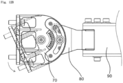
- FIGS. 12A and 12B are plan and side views illustrating rotating and tilting operations by a horizontal rotating bracket and a vertical rotating bracket among the components of the installation bracket.
- the multi input and multi output antenna apparatus 1 in accordance with the embodiment of the present disclosure may further include the installation bracket through which the multi input and multi output antenna apparatus 1 is installed on an existing antenna installation pillar.
- the installation bracket includes a heat radiation bracket 60, a vertical rotating bracket 70, a horizontal rotating bracket 80 and a pillar fixing bracket 90.
- the heat radiation bracket 60 is coupled to the plurality of rear unit heat radiation bodies 50.
- the vertical rotating bracket 70 is coupled to the heat radiation bracket 60, and provided to vertically rotate with respect to a fixed point of the antenna installation pillar.
- the horizontal rotating bracket 80 is coupled to the vertical rotating bracket 70, and provided to horizontally rotate with respect to the fixed point of the antenna installation pillar.
- the pillar fixing bracket 90 has one end coupled to the horizontal rotating bracket 80 and the other end coupled to the antenna installation pillar.
- the antenna apparatus 1 elongated in the top-to-bottom direction as the antenna apparatus 1 compared to the embodiment of the present disclosure, is installed in the longitudinal direction on the antenna installation pillar, it is substantially impossible to maintain the balance of the antenna apparatus 1 fixed to one installation pillar, due to the entire shape of the product elongated in the top-to-bottom direction.
- the angle of the antenna apparatus 1 needs to be adjusted in order to control the direction of waves emitted to/from the antenna element 13.
- the antenna apparatus 1 elongated in the top-to-bottom direction is fixed only through one installation bracket, the pressure of external wind inevitably causes the upper end or lower end of the antenna apparatus 1 to physically shake. Therefore, in general, the antenna installation pillar of the antenna apparatus 1 needs to be fixed to the antenna installation pillar through an installation bracket with a complex structure.
- the installation bracket applied to the multi input and multi output antenna apparatus 1 in accordance with the embodiment of the present disclosure may be provided in a cantilever shape on the antenna installation pillar (not illustrated), in order to fix the antenna apparatus 1
- the vertical rotating bracket 70, the horizontal rotating bracket 80 and the pillar fixing bracket 90 of the installation bracket may be rotatably provided to adjust the angle of the antenna apparatus 1.
- the angle of the antenna apparatus 1 can be adjusted in the horizontal direction through an operation of rotating the horizontal rotating bracket 80 in the side-to-side direction as illustrated in FIG. 12A , and can be adjusted in the vertical direction through an operation of rotating the vertical rotating bracket 70 in the top-to-bottom direction with respect to the horizontal rotating bracket 80, as illustrated in FIG. 12B .
- the heat radiation bracket 60 may include an installation ring part 61 formed in a ring shape to provide an installation surface of the vertical rotating bracket 70, and a plurality of fixing parts 63 extended radially from the outer surface of the installation ring part 61 and extended toward the plurality of rear unit heat radiation bodies 50.
- the installation ring part 61 may be located in the middle of the rear surface of the rear heat radiation body 31 in order to balance the entire weight of the antenna apparatus 1.
- a plurality of residual heat radiation pins 64 may be formed on the outer surface of the fixing part 63 so as to radiate heat transferred from the plurality of rear unit heat radiation bodies 50.
- the plurality of residual heat radiation pins 64 may increase the surface areas of the plurality of fixing parts 63, thereby effectively radiating the heat of the rear unit heat radiation body 50, transferred to the second heat generation elements.
- the vertical rotating bracket 70 may have a vertical guide slot 71 for guiding the rotation in the top-to-bottom direction.
- the vertical guide slot 71 serves to connect the front ends of the horizontal rotating bracket 80, and guide the vertical rotating bracket 70 to vertically move with respect to the horizontal rotating bracket 80.
- the pillar fixing bracket 90 may have a horizontal guide slot 91 for guiding the rotation in the horizontal direction.
- the horizontal guide slot 91 serves to connect the rear ends of the horizontal rotating bracket 80, and guide the horizontal rotating bracket 80 to horizontally move with respect to the pillar fixing bracket 90.
- the present disclosure provides a multi input and multi output antenna apparatus including: an antenna board having a plurality of antenna elements arranged on a front surface thereof; and a transmitting/receiving module board having a plurality of first heat generation elements provided on a front surface thereof and a plurality of second heat generation elements provided on a rear surface thereof, and disposed to have a separation space from the antenna board, wherein the first and second heat generation elements are electrically driven to generate heat.
Landscapes
- Engineering & Computer Science (AREA)
- Microelectronics & Electronic Packaging (AREA)
- Computer Networks & Wireless Communication (AREA)
- Signal Processing (AREA)
- Physics & Mathematics (AREA)
- Thermal Sciences (AREA)
- Variable-Direction Aerials And Aerial Arrays (AREA)
- Details Of Aerials (AREA)
- Support Of Aerials (AREA)
- Transceivers (AREA)
- Non-Reversible Transmitting Devices (AREA)
- Cooling Or The Like Of Electrical Apparatus (AREA)
Claims (13)
- Appareil d'antenne à entrées et sorties multiples (1) comprenant :une carte d'antenne (11) comportant plusieurs éléments d'antenne (13) disposés sur sa surface avant ; etune carte de module d'émission/réception (110) comportant une pluralité de premiers éléments de génération de chaleur (125) situés sur sa surface avant et une pluralité de seconds éléments de génération de chaleur (115) situés sur sa surface arrière, et disposée de manière à être séparée de la carte d'antenne (11), les premiers et seconds éléments de génération de chaleur (125, 115) étant entraînés électriquement pour générer de la chaleur,dans lequel la chaleur générée par la pluralité de premiers éléments de génération de chaleur (125) est diffusée à l'avant de la carte du module d'émission/réception (110), et la chaleur générée par la pluralité de seconds éléments de génération de chaleur (115) est diffusée à l'arrière de la carte du module d'émission/réception (110),comprenant en outreune unité de rayonnement thermique avant (20) configurée pour rayonner la chaleur générée par la pluralité de premiers éléments de génération de chaleur (125) ; etune unité de rayonnement thermique arrière (30) configurée pour rayonner la chaleur générée par la pluralité de seconds éléments de génération de chaleur (115),dans lequel l'unité de rayonnement thermique avant (20) comprend :un corps de rayonnement thermique avant (21) disposé en contact avec la surface avant de la carte du module d'émission/réception (110) et comportant une pluralité de broches de rayonnement thermique principales (23) faisant saillie à l'avant de celui-ci ; etune pluralité de corps de rayonnement thermique de l'unité avant (40) disposés à travers le corps de rayonnement thermique avant (21), et ayant une extrémité en contact avec au moins certains des premiers éléments de génération de chaleur (125) de la carte du module de transmission/réception (110) et les autres extrémités sur lesquelles une pluralité de broches de rayonnement thermique secondaires (43) pour le rayonnement de la chaleur conduite à partir des premiers éléments de génération de chaleur (125) vers l'extérieur sont fournies,dans lequel l'unité de rayonnement thermique arrière (30) comprend :un corps de rayonnement thermique arrière (31) disposé en contact avec la surface arrière de la carte du module d'émission/réception (110) et comportant une pluralité de broches de rayonnement thermique principales (33) faisant saillie à l'arrière de celui-ci ; etune pluralité de corps de rayonnement thermique de l'unité arrière (50) disposés à travers le corps de rayonnement thermique arrière (31), et ayant une extrémité en contact avec au moins certains des seconds éléments de génération de chaleur (115) de la carte du module de transmission/réception (110), et les autres extrémités sur lesquelles une pluralité de broches de rayonnement thermique secondaires (43) pour le rayonnement de la chaleur conduite à partir des seconds éléments de génération de chaleur (115) vers l'extérieur sont fournies.
- L'appareil d'antenne à entrées et sorties multiples de la revendication 1, comprenant en outre une pluralité de lignes d'air RF (100) disposées dans l'espace de séparation et configurées pour relier les éléments d'antenne (13) de la carte d'antenne (11) aux premiers éléments de génération de chaleur (125) de la carte de module d'émission/réception (110).
- L'appareil d'antenne à entrées et sorties multiples de la revendication 1, dans lequel la pluralité de broches de rayonnement thermique secondaires (43) de la pluralité de corps de rayonnement thermique de l'unité frontale (40) est exposée à l'espace de séparation.
- L'appareil d'antenne à entrées et sorties multiples de la revendication 1, dans lequel chacun des corps de rayonnement thermique de l'unité frontale (40) comprend :une pièce de couplage (41) couplée au corps de rayonnement thermique avant (21) de manière à être en contact avec l'un des premiers éléments de génération de chaleur (125);une partie de conduction (42) configurée pour transférer la chaleur conduite à travers la partie de couplage (41) vers l'espace de séparation ; etla pluralité de broches de sous-rayonnement thermique (43) empilées sur la circonférence extérieure de la partie de conduction (42) de manière à être espacées l'une de l'autre.
- L'appareil d'antenne à entrées et sorties multiples de la revendication 1, dans lequel la pluralité de broches principales de rayonnement thermique (33) comprend :une partie gauche de l'axe de rayonnement thermique (34) inclinée vers le haut en direction d'une ligne centrale de haut en bas du corps de rayonnement thermique arrière (31) à partir d'un côté gauche ; etune partie droite de l'axe de rayonnement thermique (35) inclinée vers le haut vers la ligne centrale de haut en bas du corps de rayonnement thermique arrière (31) à partir d'un côté droit.
- L'appareil d'antenne à entrées et sorties multiples de la revendication 1, dans lequel chacun des corps de rayonnement thermique de l'unité arrière (50) comprend :une pièce de couplage (51) couplée au corps de rayonnement thermique arrière (31) de manière à être en contact avec l'un des deuxièmes éléments de génération de chaleur (115) ;une partie de conduction (52) configurée pour transférer la chaleur conduite à travers la partie de couplage (51) vers un espace extérieur correspondant à l'extérieur du corps de rayonnement thermique arrière (31) ; etla pluralité de broches de sous-rayonnement thermique (43) empilées sur la circonférence extérieure de la partie de conduction (52) de manière à être espacées les unes des autres.
- L'appareil d'antenne à entrées et sorties multiples de la revendication 6, dans lequel la pluralité de broches de sous-rayonnement thermique (43) ont une zone de rayonnement thermique qui diminue progressivement vers l'espace extérieur.
- L'appareil d'antenne à entrées et sorties multiples de la revendication 6, dans lequel le corps de rayonnement thermique arrière (31) a un trou de couplage (37) auquel la partie de couplage (41) est couplée.
- L'appareil d'antenne à entrées et sorties multiples de la revendication 1, dans lequel la carte de module d'émission/réception (110) comprend :une première carte de transmission/réception (111) sur laquelle sont montés certains des seconds éléments de génération de chaleur (115) et qui est allongée dans le sens haut-bas sur le côté gauche de l'unité de rayonnement thermique arrière (30) ;une seconde carte de transmission/réception (112) sur laquelle sont montés certains des seconds éléments de génération de chaleur (115) et qui est allongée dans le sens haut-bas sur le côté droit de l'unité de rayonnement thermique arrière (30) ; etune troisième carte de transmission/réception (113) sur laquelle sont montés les autres éléments de génération de chaleur (115) et qui est allongée dans le sens haut-bas entre la première et la deuxième carte de transmission/réception.
- L'appareil d'antenne à entrées et sorties multiples de la revendication 9, dans lequel le corps de rayonnement thermique arrière (31) a une rainure de logement (39) dans laquelle la pluralité de seconds éléments de génération de chaleur (115) de la troisième carte d'émission/réception (113) sont placés, et qui est allongée dans la direction du haut vers le bas.
- L'appareil d'antenne à entrées et sorties multiples de la revendication 10, comprenant en outre une nervure d'évacuation du rayonnement thermique (36) formée sur la surface extérieure du corps de rayonnement thermique arrière (31) sur lequel est formée la pluralité de broches de rayonnement thermique principales (33), et faisant saillie de la surface intérieure vers la surface extérieure du corps de rayonnement thermique arrière (31), de telle sorte que la rainure d'assise (39) est formée en forme de renfoncement.
- L'appareil d'antenne à entrées et sorties multiples de la revendication 11, dans lequel la nervure d'évacuation du rayonnement thermique (36) a une section transversale horizontale ayant les sommets d'un triangle, et
la pluralité de broches principales de rayonnement thermique (33) sont étendues aux sommets de la nervure d'échappement du rayonnement thermique (36). - L'appareil d'antenne à entrées et sorties multiples de la revendication 12, dans lequel la pluralité de broches principales de rayonnement thermique (33) comprend :une partie gauche de l'axe de rayonnement thermique (34) inclinée vers le haut en direction des sommets de la nervure d'échappement du rayonnement thermique (36) à partir d'un côté gauche ; etune partie droite de l'axe de rayonnement thermique (35) inclinée vers le haut en direction des sommets de la nervure d'échappement du rayonnement thermique (36) à partir d'un côté droit,dans lequel la chaleur circulant à travers les parties gauche et droite de l'axe de rayonnement thermique (34, 35) est évacuée vers l'extérieur par la nervure d'évacuation du rayonnement thermique (36).
Applications Claiming Priority (2)
| Application Number | Priority Date | Filing Date | Title |
|---|---|---|---|
| KR20180041987 | 2018-04-11 | ||
| PCT/KR2019/004357 WO2019199078A1 (fr) | 2018-04-11 | 2019-04-11 | Appareil d'antenne à entrées multiples et sorties multiples |
Publications (3)
| Publication Number | Publication Date |
|---|---|
| EP3780260A1 EP3780260A1 (fr) | 2021-02-17 |
| EP3780260A4 EP3780260A4 (fr) | 2022-05-18 |
| EP3780260B1 true EP3780260B1 (fr) | 2024-10-23 |
Family
ID=68460226
Family Applications (1)
| Application Number | Title | Priority Date | Filing Date |
|---|---|---|---|
| EP19785289.0A Active EP3780260B1 (fr) | 2018-04-11 | 2019-04-11 | Appareil d'antenne à entrées multiples et sorties multiples |
Country Status (6)
| Country | Link |
|---|---|
| US (1) | US11147154B2 (fr) |
| EP (1) | EP3780260B1 (fr) |
| JP (2) | JP7009649B2 (fr) |
| KR (1) | KR102131417B1 (fr) |
| CN (1) | CN112352348B (fr) |
| FI (1) | FI3780260T3 (fr) |
Families Citing this family (25)
| Publication number | Priority date | Publication date | Assignee | Title |
|---|---|---|---|---|
| KR102285259B1 (ko) | 2019-06-28 | 2021-08-03 | 주식회사 케이엠더블유 | 안테나 장치 |
| KR102869451B1 (ko) | 2020-01-15 | 2025-10-17 | 주식회사 케이엠더블유 | 전장소자의 방열장치 |
| KR102505905B1 (ko) | 2020-02-07 | 2023-03-06 | 주식회사 케이엠더블유 | 전장소자의 방열장치 |
| KR102543845B1 (ko) | 2020-03-23 | 2023-06-21 | 주식회사 케이엠더블유 | 전장소자의 방열장치 |
| CN115804252A (zh) * | 2020-03-23 | 2023-03-14 | 株式会社Kmw | 电子元件的散热装置 |
| CN115836442A (zh) | 2020-05-25 | 2023-03-21 | 株式会社Kmw | 天线装置 |
| WO2021241993A1 (fr) * | 2020-05-26 | 2021-12-02 | 주식회사 케이엠더블유 | Dispositif d'antenne |
| EP4164054A4 (fr) * | 2020-06-05 | 2024-10-09 | KMW Inc. | Appareil d'antenne à entrées multiples et sorties multiples |
| KR102534806B1 (ko) * | 2020-06-05 | 2023-05-26 | 주식회사 케이엠더블유 | 다중 입출력 안테나 장치 |
| EP3930109B8 (fr) * | 2020-06-23 | 2024-08-28 | Delta Electronics (Norway) AS | Système d'alimentation comprenant un système de connexion de protection |
| KR102821123B1 (ko) * | 2020-07-02 | 2025-06-18 | 주식회사 케이엠더블유 | 솔더 기판 조립체 |
| WO2022080923A1 (fr) * | 2020-10-16 | 2022-04-21 | 주식회사 케이엠더블유 | Module rf pour antenne, ensemble module rf et appareil d'antenne comprenant ceux-ci |
| KR102519966B1 (ko) * | 2020-10-16 | 2023-04-12 | 주식회사 케이엠더블유 | 안테나용 rf 모듈, rf 모듈 조립체 및 이를 포함하는 안테나 장치 |
| KR102543846B1 (ko) * | 2020-10-20 | 2023-06-21 | 주식회사 케이엠더블유 | 안테나용 rf 모듈, rf 모듈 조립체 및 이를 포함하는 안테나 장치 |
| JP7585483B2 (ja) * | 2020-10-27 | 2024-11-18 | ケーエムダブリュ・インコーポレーテッド | アンテナ用rfモジュール、rfモジュール組立体およびこれを含むアンテナ装置 |
| EP4258468A4 (fr) * | 2020-12-02 | 2025-04-09 | KMW Inc. | Appareil d'antenne |
| KR102543847B1 (ko) * | 2020-12-02 | 2023-06-21 | 주식회사 케이엠더블유 | 안테나 장치 |
| CN116897469A (zh) * | 2020-12-08 | 2023-10-17 | 株式会社Kmw | 天线射频模块及包括其的天线装置 |
| KR20230026818A (ko) * | 2021-08-18 | 2023-02-27 | 주식회사 케이엠더블유 | 무선통신장치 |
| EP4443645A4 (fr) * | 2021-12-03 | 2025-12-31 | Kmw Inc | Appareil d'antenne |
| KR20240016896A (ko) | 2022-07-29 | 2024-02-06 | 주식회사 케이엠더블유 | 히트싱크 구조체 |
| CN119731878A (zh) | 2022-07-29 | 2025-03-28 | 株式会社Kmw | 散热器结构 |
| CN120826832A (zh) * | 2023-01-04 | 2025-10-21 | 株式会社Kmw | 多进多出天线装置 |
| WO2025008857A1 (fr) * | 2023-07-03 | 2025-01-09 | Jio Platforms Limited | Petite cellule extérieure à rendement thermique et poids optimisés |
| CN120637847A (zh) * | 2024-03-11 | 2025-09-12 | 群迈通讯股份有限公司 | 散热模组及具有该散热模组的天线阵列装置 |
Family Cites Families (39)
| Publication number | Priority date | Publication date | Assignee | Title |
|---|---|---|---|---|
| SE504951C2 (sv) * | 1995-09-29 | 1997-06-02 | Ericsson Telefon Ab L M | Anordning vid antennenheter |
| US7043280B1 (en) * | 2001-10-11 | 2006-05-09 | Adaptix, Inc. | Mechanically rotatable wireless RF data transmission subscriber station with multi-beam antenna |
| JP3893496B2 (ja) * | 2002-07-03 | 2007-03-14 | 三菱電機株式会社 | アンテナ装置 |
| US7136017B2 (en) * | 2004-09-22 | 2006-11-14 | Navini Networks, Inc. | Pin fin ground plane for a patch antenna |
| KR100646582B1 (ko) * | 2004-12-10 | 2006-11-23 | 세원텔레텍 주식회사 | 중계기 및 기지국 함체구조 |
| CN2894099Y (zh) * | 2006-03-01 | 2007-04-25 | 尚桦科技股份有限公司 | 无线网络接收器的壳体改良结构 |
| CN102273007B (zh) * | 2008-12-02 | 2013-11-06 | 安德鲁有限责任公司 | 天线散热翼片 |
| US8045329B2 (en) * | 2009-04-29 | 2011-10-25 | Raytheon Company | Thermal dissipation mechanism for an antenna |
| BR112012013364A8 (pt) * | 2009-12-02 | 2018-02-06 | Andrew Llc | Antena de painel que tem caixa vedada de rádio |
| US8659901B2 (en) * | 2010-02-04 | 2014-02-25 | P-Wave-Holdings, LLC | Active antenna array heatsink |
| US9209523B2 (en) * | 2012-02-24 | 2015-12-08 | Futurewei Technologies, Inc. | Apparatus and method for modular multi-sector active antenna system |
| JP5928233B2 (ja) | 2012-08-03 | 2016-06-01 | 富士通株式会社 | 放熱器及び該放熱器を備えた電子装置 |
| US9083414B2 (en) * | 2012-08-09 | 2015-07-14 | GM Global Technology Operations LLC | LTE MIMO-capable multi-functional vehicle antenna |
| JP5920121B2 (ja) * | 2012-09-03 | 2016-05-18 | 株式会社デンソー | 車載用アンテナ装置 |
| JP5920123B2 (ja) * | 2012-09-03 | 2016-05-18 | 株式会社日本自動車部品総合研究所 | 車載用アンテナ装置 |
| GB2507788A (en) * | 2012-11-09 | 2014-05-14 | Univ Birmingham | Vehicle roof mounted reconfigurable MIMO antenna |
| US9147927B2 (en) | 2013-08-14 | 2015-09-29 | The Directv Group, Inc. | Antenna systems for wireless devices |
| KR20150145084A (ko) * | 2014-06-18 | 2015-12-29 | 주식회사 케이엠더블유 | 방열 장치 |
| FR3032556B1 (fr) * | 2015-02-11 | 2017-03-17 | Commissariat Energie Atomique | Dispositif de transmission rf a reflecteur d'ondes electromagnetiques integre |
| EP3254334B1 (fr) * | 2015-02-26 | 2023-11-22 | Huawei Technologies Co., Ltd. | Boîtier d'unité radio et module d'antenne de station de base |
| EP3286801B1 (fr) * | 2015-04-20 | 2022-12-28 | InterDigital Madison Patent Holdings, SAS | Connecteur de câblage d'antenne à détendeur dans un dispositif électronique |
| GB2539724A (en) * | 2015-06-25 | 2016-12-28 | Airspan Networks Inc | A rotable antenna apparatus |
| GB2539723A (en) * | 2015-06-25 | 2016-12-28 | Airspan Networks Inc | A rotable antenna apparatus |
| JP6848863B2 (ja) * | 2015-07-08 | 2021-03-24 | 日本電気株式会社 | 無線通信装置 |
| EP3327767B1 (fr) * | 2015-07-24 | 2020-04-29 | Nec Corporation | Structure de montage, procédé de fabrication de structure de montage, et dispositif sans fil |
| JP6520568B2 (ja) | 2015-08-25 | 2019-05-29 | 住友電気工業株式会社 | アンテナ装置 |
| US10224618B2 (en) * | 2015-09-14 | 2019-03-05 | Advanced Automotive Antennas, S.L.U. | MIMO antenna system for a vehicle |
| JP2017063288A (ja) | 2015-09-24 | 2017-03-30 | 住友電気工業株式会社 | アンテナシステム |
| CN105356051B (zh) * | 2015-11-16 | 2018-02-23 | 中国电子科技集团公司第十研究所 | 大功率导引头瓦式有源相控阵天线 |
| JP6525064B2 (ja) * | 2015-11-19 | 2019-06-05 | 日本電気株式会社 | 無線通信装置 |
| US20170156240A1 (en) | 2015-11-30 | 2017-06-01 | Abb Technology Oy | Cooled power electronic assembly |
| US10750641B2 (en) * | 2015-12-17 | 2020-08-18 | Mitsubishi Electric Corporation | Phased array antenna |
| JP6589101B2 (ja) | 2015-12-25 | 2019-10-16 | Kddi株式会社 | アンテナ装置 |
| US10263476B2 (en) * | 2015-12-29 | 2019-04-16 | Energous Corporation | Transmitter board allowing for modular antenna configurations in wireless power transmission systems |
| KR101806173B1 (ko) | 2016-04-29 | 2017-12-07 | 주식회사 케이엠더블유 | Mimo 서비스를 지원하는 안테나 분산 시스템 |
| CN105978819A (zh) * | 2016-06-22 | 2016-09-28 | 上海闪店联信息科技有限公司 | 路由器 |
| KR101852580B1 (ko) * | 2016-08-31 | 2018-06-11 | 엘지전자 주식회사 | 차량에 탑재되는 안테나 시스템 |
| KR102501935B1 (ko) * | 2016-08-31 | 2023-02-21 | 삼성전자 주식회사 | 안테나 장치 및 이를 포함하는 전자 기기 |
| US10128563B2 (en) * | 2017-01-17 | 2018-11-13 | Wistron Neweb Corporation | Wireless communication device |
-
2019
- 2019-04-11 CN CN201980025429.7A patent/CN112352348B/zh active Active
- 2019-04-11 KR KR1020190042379A patent/KR102131417B1/ko active Active
- 2019-04-11 JP JP2020555219A patent/JP7009649B2/ja active Active
- 2019-04-11 EP EP19785289.0A patent/EP3780260B1/fr active Active
- 2019-04-11 FI FIEP19785289.0T patent/FI3780260T3/fi active
-
2020
- 2020-10-08 US US17/065,739 patent/US11147154B2/en active Active
-
2022
- 2022-01-12 JP JP2022003030A patent/JP7285348B2/ja active Active
Also Published As
| Publication number | Publication date |
|---|---|
| US20210029819A1 (en) | 2021-01-28 |
| CN112352348B (zh) | 2024-07-02 |
| FI3780260T3 (fi) | 2025-01-23 |
| JP7285348B2 (ja) | 2023-06-01 |
| EP3780260A4 (fr) | 2022-05-18 |
| KR20190118979A (ko) | 2019-10-21 |
| EP3780260A1 (fr) | 2021-02-17 |
| CN112352348A (zh) | 2021-02-09 |
| JP7009649B2 (ja) | 2022-02-10 |
| JP2021520140A (ja) | 2021-08-12 |
| JP2022036235A (ja) | 2022-03-04 |
| US11147154B2 (en) | 2021-10-12 |
| KR102131417B1 (ko) | 2020-07-08 |
Similar Documents
| Publication | Publication Date | Title |
|---|---|---|
| EP3780260B1 (fr) | Appareil d'antenne à entrées multiples et sorties multiples | |
| EP3491697B1 (fr) | Réseau d'antennes à point d'accès multibandes | |
| US11165136B2 (en) | Flex integrated antenna array | |
| US10985453B2 (en) | Low profile high performance integrated antenna for small cell base station | |
| CN116169455B (zh) | 具有天线阻塞最小化的紧凑型模块化有源-无源天线系统 | |
| CN211907697U (zh) | 一种共形电扫阵列天线 | |
| US11735819B2 (en) | Compact patch and dipole interleaved array antenna | |
| US20140354510A1 (en) | Antenna system providing simultaneously identical main beam radiation characteristics for independent polarizations | |
| US10770798B2 (en) | Flex cable fed antenna system | |
| US20200052414A1 (en) | Methods circuits devices assemblies and systems for wireless communication | |
| US11594823B2 (en) | Discrete antenna module with via wall structure | |
| WO2015120417A2 (fr) | Réseau en étoile d'antennes à large bande | |
| CN217740763U (zh) | 一种相控阵天线结构 | |
| KR20260030094A (ko) | 안테나 모듈 및 이를 포함하는 전자 장치 | |
| US20190334622A1 (en) | Fiber integrated radio equipment for network optimization and densification ecosystem (fire-node) | |
| US11937393B2 (en) | Circuit board assembly and system for communication to an access point of an avionics network | |
| CN117810670A (zh) | 星载有源相控阵天线 | |
| EP4293826A1 (fr) | Antenne et dispositif électronique comprenant celle-ci | |
| US20180159247A1 (en) | Antenna arrays with common phase centers | |
| US20200076471A1 (en) | High bandwidth scalable wireless near-field interface | |
| KR101599216B1 (ko) | 다중 안테나 조립체 및 이를 포함하는 시스템 | |
| KR200379436Y1 (ko) | 무선통신 송수신장치의 안테나 장착구조 | |
| KR20240023242A (ko) | 무선 모듈 및 이를 포함하는 전자 장치 | |
| CN121885983A (zh) | LoRa天线及基于LoRa天线的新能源微电网监控系统 | |
| WO2025241932A1 (fr) | Unité d'antenne, antenne, système d'antenne et station de base |
Legal Events
| Date | Code | Title | Description |
|---|---|---|---|
| STAA | Information on the status of an ep patent application or granted ep patent |
Free format text: STATUS: THE INTERNATIONAL PUBLICATION HAS BEEN MADE |
|
| PUAI | Public reference made under article 153(3) epc to a published international application that has entered the european phase |
Free format text: ORIGINAL CODE: 0009012 |
|
| STAA | Information on the status of an ep patent application or granted ep patent |
Free format text: STATUS: REQUEST FOR EXAMINATION WAS MADE |
|
| 17P | Request for examination filed |
Effective date: 20201020 |
|
| AK | Designated contracting states |
Kind code of ref document: A1 Designated state(s): AL AT BE BG CH CY CZ DE DK EE ES FI FR GB GR HR HU IE IS IT LI LT LU LV MC MK MT NL NO PL PT RO RS SE SI SK SM TR |
|
| AX | Request for extension of the european patent |
Extension state: BA ME |
|
| DAV | Request for validation of the european patent (deleted) | ||
| DAX | Request for extension of the european patent (deleted) | ||
| A4 | Supplementary search report drawn up and despatched |
Effective date: 20220420 |
|
| RIC1 | Information provided on ipc code assigned before grant |
Ipc: H04B 1/40 20150101ALI20220412BHEP Ipc: H01Q 21/00 20060101ALI20220412BHEP Ipc: H05K 7/20 20060101ALI20220412BHEP Ipc: H01Q 1/38 20060101ALI20220412BHEP Ipc: H01Q 1/42 20060101ALI20220412BHEP Ipc: H01Q 1/02 20060101AFI20220412BHEP |
|
| GRAP | Despatch of communication of intention to grant a patent |
Free format text: ORIGINAL CODE: EPIDOSNIGR1 |
|
| STAA | Information on the status of an ep patent application or granted ep patent |
Free format text: STATUS: GRANT OF PATENT IS INTENDED |
|
| INTG | Intention to grant announced |
Effective date: 20240513 |
|
| GRAS | Grant fee paid |
Free format text: ORIGINAL CODE: EPIDOSNIGR3 |
|
| GRAA | (expected) grant |
Free format text: ORIGINAL CODE: 0009210 |
|
| STAA | Information on the status of an ep patent application or granted ep patent |
Free format text: STATUS: THE PATENT HAS BEEN GRANTED |
|
| AK | Designated contracting states |
Kind code of ref document: B1 Designated state(s): AL AT BE BG CH CY CZ DE DK EE ES FI FR GB GR HR HU IE IS IT LI LT LU LV MC MK MT NL NO PL PT RO RS SE SI SK SM TR |
|
| REG | Reference to a national code |
Ref country code: GB Ref legal event code: FG4D |
|
| REG | Reference to a national code |
Ref country code: CH Ref legal event code: EP |
|
| REG | Reference to a national code |
Ref country code: DE Ref legal event code: R096 Ref document number: 602019060835 Country of ref document: DE |
|
| REG | Reference to a national code |
Ref country code: IE Ref legal event code: FG4D |
|
| REG | Reference to a national code |
Ref country code: FI Ref legal event code: FGE |
|
| REG | Reference to a national code |
Ref country code: LT Ref legal event code: MG9D |
|
| REG | Reference to a national code |
Ref country code: NL Ref legal event code: MP Effective date: 20241023 |
|
| REG | Reference to a national code |
Ref country code: AT Ref legal event code: MK05 Ref document number: 1735608 Country of ref document: AT Kind code of ref document: T Effective date: 20241023 |
|
| PG25 | Lapsed in a contracting state [announced via postgrant information from national office to epo] |
Ref country code: NL Free format text: LAPSE BECAUSE OF FAILURE TO SUBMIT A TRANSLATION OF THE DESCRIPTION OR TO PAY THE FEE WITHIN THE PRESCRIBED TIME-LIMIT Effective date: 20241023 |
|
| PG25 | Lapsed in a contracting state [announced via postgrant information from national office to epo] |
Ref country code: NL Free format text: LAPSE BECAUSE OF FAILURE TO SUBMIT A TRANSLATION OF THE DESCRIPTION OR TO PAY THE FEE WITHIN THE PRESCRIBED TIME-LIMIT Effective date: 20241023 |
|
| PG25 | Lapsed in a contracting state [announced via postgrant information from national office to epo] |
Ref country code: PT Free format text: LAPSE BECAUSE OF FAILURE TO SUBMIT A TRANSLATION OF THE DESCRIPTION OR TO PAY THE FEE WITHIN THE PRESCRIBED TIME-LIMIT Effective date: 20250224 Ref country code: IS Free format text: LAPSE BECAUSE OF FAILURE TO SUBMIT A TRANSLATION OF THE DESCRIPTION OR TO PAY THE FEE WITHIN THE PRESCRIBED TIME-LIMIT Effective date: 20250223 Ref country code: HR Free format text: LAPSE BECAUSE OF FAILURE TO SUBMIT A TRANSLATION OF THE DESCRIPTION OR TO PAY THE FEE WITHIN THE PRESCRIBED TIME-LIMIT Effective date: 20241023 |
|
| PG25 | Lapsed in a contracting state [announced via postgrant information from national office to epo] |
Ref country code: BG Free format text: LAPSE BECAUSE OF FAILURE TO SUBMIT A TRANSLATION OF THE DESCRIPTION OR TO PAY THE FEE WITHIN THE PRESCRIBED TIME-LIMIT Effective date: 20241023 |
|
| PG25 | Lapsed in a contracting state [announced via postgrant information from national office to epo] |
Ref country code: ES Free format text: LAPSE BECAUSE OF FAILURE TO SUBMIT A TRANSLATION OF THE DESCRIPTION OR TO PAY THE FEE WITHIN THE PRESCRIBED TIME-LIMIT Effective date: 20241023 |
|
| PG25 | Lapsed in a contracting state [announced via postgrant information from national office to epo] |
Ref country code: NO Free format text: LAPSE BECAUSE OF FAILURE TO SUBMIT A TRANSLATION OF THE DESCRIPTION OR TO PAY THE FEE WITHIN THE PRESCRIBED TIME-LIMIT Effective date: 20250123 |
|
| PG25 | Lapsed in a contracting state [announced via postgrant information from national office to epo] |
Ref country code: LV Free format text: LAPSE BECAUSE OF FAILURE TO SUBMIT A TRANSLATION OF THE DESCRIPTION OR TO PAY THE FEE WITHIN THE PRESCRIBED TIME-LIMIT Effective date: 20241023 Ref country code: GR Free format text: LAPSE BECAUSE OF FAILURE TO SUBMIT A TRANSLATION OF THE DESCRIPTION OR TO PAY THE FEE WITHIN THE PRESCRIBED TIME-LIMIT Effective date: 20250124 Ref country code: AT Free format text: LAPSE BECAUSE OF FAILURE TO SUBMIT A TRANSLATION OF THE DESCRIPTION OR TO PAY THE FEE WITHIN THE PRESCRIBED TIME-LIMIT Effective date: 20241023 |
|
| PG25 | Lapsed in a contracting state [announced via postgrant information from national office to epo] |
Ref country code: PL Free format text: LAPSE BECAUSE OF FAILURE TO SUBMIT A TRANSLATION OF THE DESCRIPTION OR TO PAY THE FEE WITHIN THE PRESCRIBED TIME-LIMIT Effective date: 20241023 |
|
| PG25 | Lapsed in a contracting state [announced via postgrant information from national office to epo] |
Ref country code: RS Free format text: LAPSE BECAUSE OF FAILURE TO SUBMIT A TRANSLATION OF THE DESCRIPTION OR TO PAY THE FEE WITHIN THE PRESCRIBED TIME-LIMIT Effective date: 20250123 |
|
| PG25 | Lapsed in a contracting state [announced via postgrant information from national office to epo] |
Ref country code: SM Free format text: LAPSE BECAUSE OF FAILURE TO SUBMIT A TRANSLATION OF THE DESCRIPTION OR TO PAY THE FEE WITHIN THE PRESCRIBED TIME-LIMIT Effective date: 20241023 |
|
| PGFP | Annual fee paid to national office [announced via postgrant information from national office to epo] |
Ref country code: FI Payment date: 20250421 Year of fee payment: 7 |
|
| PG25 | Lapsed in a contracting state [announced via postgrant information from national office to epo] |
Ref country code: DK Free format text: LAPSE BECAUSE OF FAILURE TO SUBMIT A TRANSLATION OF THE DESCRIPTION OR TO PAY THE FEE WITHIN THE PRESCRIBED TIME-LIMIT Effective date: 20241023 |
|
| PG25 | Lapsed in a contracting state [announced via postgrant information from national office to epo] |
Ref country code: EE Free format text: LAPSE BECAUSE OF FAILURE TO SUBMIT A TRANSLATION OF THE DESCRIPTION OR TO PAY THE FEE WITHIN THE PRESCRIBED TIME-LIMIT Effective date: 20241023 |
|
| PG25 | Lapsed in a contracting state [announced via postgrant information from national office to epo] |
Ref country code: RO Free format text: LAPSE BECAUSE OF FAILURE TO SUBMIT A TRANSLATION OF THE DESCRIPTION OR TO PAY THE FEE WITHIN THE PRESCRIBED TIME-LIMIT Effective date: 20241023 |
|
| REG | Reference to a national code |
Ref country code: DE Ref legal event code: R097 Ref document number: 602019060835 Country of ref document: DE |
|
| PG25 | Lapsed in a contracting state [announced via postgrant information from national office to epo] |
Ref country code: SK Free format text: LAPSE BECAUSE OF FAILURE TO SUBMIT A TRANSLATION OF THE DESCRIPTION OR TO PAY THE FEE WITHIN THE PRESCRIBED TIME-LIMIT Effective date: 20241023 |
|
| PG25 | Lapsed in a contracting state [announced via postgrant information from national office to epo] |
Ref country code: CZ Free format text: LAPSE BECAUSE OF FAILURE TO SUBMIT A TRANSLATION OF THE DESCRIPTION OR TO PAY THE FEE WITHIN THE PRESCRIBED TIME-LIMIT Effective date: 20241023 |
|
| PG25 | Lapsed in a contracting state [announced via postgrant information from national office to epo] |
Ref country code: IT Free format text: LAPSE BECAUSE OF FAILURE TO SUBMIT A TRANSLATION OF THE DESCRIPTION OR TO PAY THE FEE WITHIN THE PRESCRIBED TIME-LIMIT Effective date: 20241023 |
|
| PLBE | No opposition filed within time limit |
Free format text: ORIGINAL CODE: 0009261 |
|
| STAA | Information on the status of an ep patent application or granted ep patent |
Free format text: STATUS: NO OPPOSITION FILED WITHIN TIME LIMIT |
|
| PG25 | Lapsed in a contracting state [announced via postgrant information from national office to epo] |
Ref country code: SE Free format text: LAPSE BECAUSE OF FAILURE TO SUBMIT A TRANSLATION OF THE DESCRIPTION OR TO PAY THE FEE WITHIN THE PRESCRIBED TIME-LIMIT Effective date: 20241023 |
|
| 26N | No opposition filed |
Effective date: 20250724 |
|
| REG | Reference to a national code |
Ref country code: DE Ref legal event code: R119 Ref document number: 602019060835 Country of ref document: DE |
|
| REG | Reference to a national code |
Ref country code: CH Ref legal event code: H13 Free format text: ST27 STATUS EVENT CODE: U-0-0-H10-H13 (AS PROVIDED BY THE NATIONAL OFFICE) Effective date: 20251125 |
|
| PG25 | Lapsed in a contracting state [announced via postgrant information from national office to epo] |
Ref country code: LU Free format text: LAPSE BECAUSE OF NON-PAYMENT OF DUE FEES Effective date: 20250411 |
|
| PG25 | Lapsed in a contracting state [announced via postgrant information from national office to epo] |
Ref country code: MC Free format text: LAPSE BECAUSE OF FAILURE TO SUBMIT A TRANSLATION OF THE DESCRIPTION OR TO PAY THE FEE WITHIN THE PRESCRIBED TIME-LIMIT Effective date: 20241023 |
|
| GBPC | Gb: european patent ceased through non-payment of renewal fee |
Effective date: 20250411 |
|
| REG | Reference to a national code |
Ref country code: BE Ref legal event code: MM Effective date: 20250430 |
|
| PG25 | Lapsed in a contracting state [announced via postgrant information from national office to epo] |
Ref country code: DE Free format text: LAPSE BECAUSE OF NON-PAYMENT OF DUE FEES Effective date: 20251104 |
|
| PG25 | Lapsed in a contracting state [announced via postgrant information from national office to epo] |
Ref country code: GB Free format text: LAPSE BECAUSE OF NON-PAYMENT OF DUE FEES Effective date: 20250411 |
|
| PG25 | Lapsed in a contracting state [announced via postgrant information from national office to epo] |
Ref country code: FR Free format text: LAPSE BECAUSE OF NON-PAYMENT OF DUE FEES Effective date: 20250430 |
|
| PG25 | Lapsed in a contracting state [announced via postgrant information from national office to epo] |
Ref country code: BE Free format text: LAPSE BECAUSE OF NON-PAYMENT OF DUE FEES Effective date: 20250430 |
|
| PG25 | Lapsed in a contracting state [announced via postgrant information from national office to epo] |
Ref country code: CH Free format text: LAPSE BECAUSE OF NON-PAYMENT OF DUE FEES Effective date: 20250430 |
|
| PG25 | Lapsed in a contracting state [announced via postgrant information from national office to epo] |
Ref country code: IE Free format text: LAPSE BECAUSE OF NON-PAYMENT OF DUE FEES Effective date: 20250411 |