EP3780363A1 - Dispositif et procédé de revêtement d'adhésif - Google Patents
Dispositif et procédé de revêtement d'adhésif Download PDFInfo
- Publication number
- EP3780363A1 EP3780363A1 EP19759989.7A EP19759989A EP3780363A1 EP 3780363 A1 EP3780363 A1 EP 3780363A1 EP 19759989 A EP19759989 A EP 19759989A EP 3780363 A1 EP3780363 A1 EP 3780363A1
- Authority
- EP
- European Patent Office
- Prior art keywords
- adhesive
- steel strip
- thin steel
- container
- dispense
- Prior art date
- Legal status (The legal status is an assumption and is not a legal conclusion. Google has not performed a legal analysis and makes no representation as to the accuracy of the status listed.)
- Withdrawn
Links
- 239000000853 adhesive Substances 0.000 title claims abstract description 299
- 230000001070 adhesive effect Effects 0.000 title claims abstract description 299
- 238000000576 coating method Methods 0.000 title 2
- 239000011248 coating agent Substances 0.000 title 1
- 229910000831 Steel Inorganic materials 0.000 claims abstract description 149
- 239000010959 steel Substances 0.000 claims abstract description 149
- 238000004080 punching Methods 0.000 claims abstract description 23
- 238000000034 method Methods 0.000 claims abstract description 19
- 230000003028 elevating effect Effects 0.000 claims description 9
- 238000010438 heat treatment Methods 0.000 claims description 7
- 238000004519 manufacturing process Methods 0.000 abstract description 10
- 230000006872 improvement Effects 0.000 abstract description 2
- 239000007788 liquid Substances 0.000 description 9
- 238000003475 lamination Methods 0.000 description 5
- 238000010586 diagram Methods 0.000 description 4
- 238000003825 pressing Methods 0.000 description 4
- 230000008569 process Effects 0.000 description 3
- 238000003860 storage Methods 0.000 description 2
- 230000001133 acceleration Effects 0.000 description 1
- 230000004075 alteration Effects 0.000 description 1
- 230000006866 deterioration Effects 0.000 description 1
- 230000000694 effects Effects 0.000 description 1
- 238000012423 maintenance Methods 0.000 description 1
- 239000000463 material Substances 0.000 description 1
- 238000012986 modification Methods 0.000 description 1
- 230000004048 modification Effects 0.000 description 1
- 230000000750 progressive effect Effects 0.000 description 1
- 238000011084 recovery Methods 0.000 description 1
- XLYOFNOQVPJJNP-UHFFFAOYSA-N water Substances O XLYOFNOQVPJJNP-UHFFFAOYSA-N 0.000 description 1
- 238000003466 welding Methods 0.000 description 1
Images




Classifications
-
- B—PERFORMING OPERATIONS; TRANSPORTING
- B05—SPRAYING OR ATOMISING IN GENERAL; APPLYING FLUENT MATERIALS TO SURFACES, IN GENERAL
- B05D—PROCESSES FOR APPLYING FLUENT MATERIALS TO SURFACES, IN GENERAL
- B05D5/00—Processes for applying liquids or other fluent materials to surfaces to obtain special surface effects, finishes or structures
- B05D5/10—Processes for applying liquids or other fluent materials to surfaces to obtain special surface effects, finishes or structures to obtain an adhesive surface
-
- B—PERFORMING OPERATIONS; TRANSPORTING
- B05—SPRAYING OR ATOMISING IN GENERAL; APPLYING FLUENT MATERIALS TO SURFACES, IN GENERAL
- B05C—APPARATUS FOR APPLYING FLUENT MATERIALS TO SURFACES, IN GENERAL
- B05C9/00—Apparatus or plant for applying liquid or other fluent material to surfaces by means not covered by any preceding group, or in which the means of applying the liquid or other fluent material is not important
- B05C9/08—Apparatus or plant for applying liquid or other fluent material to surfaces by means not covered by any preceding group, or in which the means of applying the liquid or other fluent material is not important for applying liquid or other fluent material and performing an auxiliary operation
- B05C9/14—Apparatus or plant for applying liquid or other fluent material to surfaces by means not covered by any preceding group, or in which the means of applying the liquid or other fluent material is not important for applying liquid or other fluent material and performing an auxiliary operation the auxiliary operation involving heating or cooling
-
- B—PERFORMING OPERATIONS; TRANSPORTING
- B05—SPRAYING OR ATOMISING IN GENERAL; APPLYING FLUENT MATERIALS TO SURFACES, IN GENERAL
- B05C—APPARATUS FOR APPLYING FLUENT MATERIALS TO SURFACES, IN GENERAL
- B05C11/00—Component parts, details or accessories not specifically provided for in groups B05C1/00 - B05C9/00
- B05C11/10—Storage, supply or control of liquid or other fluent material; Recovery of excess liquid or other fluent material
-
- B—PERFORMING OPERATIONS; TRANSPORTING
- B05—SPRAYING OR ATOMISING IN GENERAL; APPLYING FLUENT MATERIALS TO SURFACES, IN GENERAL
- B05C—APPARATUS FOR APPLYING FLUENT MATERIALS TO SURFACES, IN GENERAL
- B05C11/00—Component parts, details or accessories not specifically provided for in groups B05C1/00 - B05C9/00
- B05C11/10—Storage, supply or control of liquid or other fluent material; Recovery of excess liquid or other fluent material
- B05C11/1042—Storage, supply or control of liquid or other fluent material; Recovery of excess liquid or other fluent material provided with means for heating or cooling the liquid or other fluent material in the supplying means upstream of the applying apparatus
-
- B—PERFORMING OPERATIONS; TRANSPORTING
- B05—SPRAYING OR ATOMISING IN GENERAL; APPLYING FLUENT MATERIALS TO SURFACES, IN GENERAL
- B05C—APPARATUS FOR APPLYING FLUENT MATERIALS TO SURFACES, IN GENERAL
- B05C13/00—Means for manipulating or holding work, e.g. for separate articles
- B05C13/02—Means for manipulating or holding work, e.g. for separate articles for particular articles
-
- B—PERFORMING OPERATIONS; TRANSPORTING
- B05—SPRAYING OR ATOMISING IN GENERAL; APPLYING FLUENT MATERIALS TO SURFACES, IN GENERAL
- B05C—APPARATUS FOR APPLYING FLUENT MATERIALS TO SURFACES, IN GENERAL
- B05C5/00—Apparatus in which liquid or other fluent material is projected, poured or allowed to flow on to the surface of the work
- B05C5/02—Apparatus in which liquid or other fluent material is projected, poured or allowed to flow on to the surface of the work the liquid or other fluent material being discharged through an outlet orifice by pressure, e.g. from an outlet device in contact or almost in contact, with the work
-
- B—PERFORMING OPERATIONS; TRANSPORTING
- B05—SPRAYING OR ATOMISING IN GENERAL; APPLYING FLUENT MATERIALS TO SURFACES, IN GENERAL
- B05D—PROCESSES FOR APPLYING FLUENT MATERIALS TO SURFACES, IN GENERAL
- B05D1/00—Processes for applying liquids or other fluent materials
- B05D1/26—Processes for applying liquids or other fluent materials performed by applying the liquid or other fluent material from an outlet device in contact with, or almost in contact with, the surface
-
- B—PERFORMING OPERATIONS; TRANSPORTING
- B05—SPRAYING OR ATOMISING IN GENERAL; APPLYING FLUENT MATERIALS TO SURFACES, IN GENERAL
- B05D—PROCESSES FOR APPLYING FLUENT MATERIALS TO SURFACES, IN GENERAL
- B05D3/00—Pretreatment of surfaces to which liquids or other fluent materials are to be applied; After-treatment of applied coatings, e.g. intermediate treating of an applied coating preparatory to subsequent applications of liquids or other fluent materials
-
- B—PERFORMING OPERATIONS; TRANSPORTING
- B05—SPRAYING OR ATOMISING IN GENERAL; APPLYING FLUENT MATERIALS TO SURFACES, IN GENERAL
- B05D—PROCESSES FOR APPLYING FLUENT MATERIALS TO SURFACES, IN GENERAL
- B05D7/00—Processes, other than flocking, specially adapted for applying liquids or other fluent materials to particular surfaces or for applying particular liquids or other fluent materials
- B05D7/24—Processes, other than flocking, specially adapted for applying liquids or other fluent materials to particular surfaces or for applying particular liquids or other fluent materials for applying particular liquids or other fluent materials
-
- B—PERFORMING OPERATIONS; TRANSPORTING
- B32—LAYERED PRODUCTS
- B32B—LAYERED PRODUCTS, i.e. PRODUCTS BUILT-UP OF STRATA OF FLAT OR NON-FLAT, e.g. CELLULAR OR HONEYCOMB, FORM
- B32B37/00—Methods or apparatus for laminating, e.g. by curing or by ultrasonic bonding
- B32B37/12—Methods or apparatus for laminating, e.g. by curing or by ultrasonic bonding characterised by using adhesives
-
- H—ELECTRICITY
- H01—ELECTRIC ELEMENTS
- H01F—MAGNETS; INDUCTANCES; TRANSFORMERS; SELECTION OF MATERIALS FOR THEIR MAGNETIC PROPERTIES
- H01F41/00—Apparatus or processes specially adapted for manufacturing or assembling magnets, inductances or transformers; Apparatus or processes specially adapted for manufacturing materials characterised by their magnetic properties
- H01F41/02—Apparatus or processes specially adapted for manufacturing or assembling magnets, inductances or transformers; Apparatus or processes specially adapted for manufacturing materials characterised by their magnetic properties for manufacturing cores, coils, or magnets
-
- H—ELECTRICITY
- H01—ELECTRIC ELEMENTS
- H01F—MAGNETS; INDUCTANCES; TRANSFORMERS; SELECTION OF MATERIALS FOR THEIR MAGNETIC PROPERTIES
- H01F41/00—Apparatus or processes specially adapted for manufacturing or assembling magnets, inductances or transformers; Apparatus or processes specially adapted for manufacturing materials characterised by their magnetic properties
- H01F41/02—Apparatus or processes specially adapted for manufacturing or assembling magnets, inductances or transformers; Apparatus or processes specially adapted for manufacturing materials characterised by their magnetic properties for manufacturing cores, coils, or magnets
- H01F41/0206—Manufacturing of magnetic cores by mechanical means
- H01F41/0233—Manufacturing of magnetic circuits made from sheets
-
- H—ELECTRICITY
- H02—GENERATION; CONVERSION OR DISTRIBUTION OF ELECTRIC POWER
- H02K—DYNAMO-ELECTRIC MACHINES
- H02K15/00—Processes or apparatus specially adapted for manufacturing, assembling, maintaining or repairing of dynamo-electric machines
- H02K15/02—Processes or apparatus specially adapted for manufacturing, assembling, maintaining or repairing of dynamo-electric machines of stator or rotor bodies
-
- B—PERFORMING OPERATIONS; TRANSPORTING
- B05—SPRAYING OR ATOMISING IN GENERAL; APPLYING FLUENT MATERIALS TO SURFACES, IN GENERAL
- B05C—APPARATUS FOR APPLYING FLUENT MATERIALS TO SURFACES, IN GENERAL
- B05C11/00—Component parts, details or accessories not specifically provided for in groups B05C1/00 - B05C9/00
- B05C11/10—Storage, supply or control of liquid or other fluent material; Recovery of excess liquid or other fluent material
- B05C11/1002—Means for controlling supply, i.e. flow or pressure, of liquid or other fluent material to the applying apparatus, e.g. valves
- B05C11/1007—Means for controlling supply, i.e. flow or pressure, of liquid or other fluent material to the applying apparatus, e.g. valves responsive to condition of liquid or other fluent material
- B05C11/1013—Means for controlling supply, i.e. flow or pressure, of liquid or other fluent material to the applying apparatus, e.g. valves responsive to condition of liquid or other fluent material responsive to flow or pressure of liquid or other fluent material
-
- B—PERFORMING OPERATIONS; TRANSPORTING
- B05—SPRAYING OR ATOMISING IN GENERAL; APPLYING FLUENT MATERIALS TO SURFACES, IN GENERAL
- B05C—APPARATUS FOR APPLYING FLUENT MATERIALS TO SURFACES, IN GENERAL
- B05C5/00—Apparatus in which liquid or other fluent material is projected, poured or allowed to flow on to the surface of the work
- B05C5/001—Apparatus in which liquid or other fluent material is projected, poured or allowed to flow on to the surface of the work incorporating means for heating or cooling the liquid or other fluent material
-
- B—PERFORMING OPERATIONS; TRANSPORTING
- B05—SPRAYING OR ATOMISING IN GENERAL; APPLYING FLUENT MATERIALS TO SURFACES, IN GENERAL
- B05C—APPARATUS FOR APPLYING FLUENT MATERIALS TO SURFACES, IN GENERAL
- B05C5/00—Apparatus in which liquid or other fluent material is projected, poured or allowed to flow on to the surface of the work
- B05C5/02—Apparatus in which liquid or other fluent material is projected, poured or allowed to flow on to the surface of the work the liquid or other fluent material being discharged through an outlet orifice by pressure, e.g. from an outlet device in contact or almost in contact, with the work
- B05C5/027—Coating heads with several outlets, e.g. aligned transversally to the moving direction of a web to be coated
-
- B—PERFORMING OPERATIONS; TRANSPORTING
- B05—SPRAYING OR ATOMISING IN GENERAL; APPLYING FLUENT MATERIALS TO SURFACES, IN GENERAL
- B05D—PROCESSES FOR APPLYING FLUENT MATERIALS TO SURFACES, IN GENERAL
- B05D2202/00—Metallic substrate
- B05D2202/10—Metallic substrate based on Fe
-
- B—PERFORMING OPERATIONS; TRANSPORTING
- B05—SPRAYING OR ATOMISING IN GENERAL; APPLYING FLUENT MATERIALS TO SURFACES, IN GENERAL
- B05D—PROCESSES FOR APPLYING FLUENT MATERIALS TO SURFACES, IN GENERAL
- B05D2252/00—Sheets
- B05D2252/02—Sheets of indefinite length
-
- B—PERFORMING OPERATIONS; TRANSPORTING
- B05—SPRAYING OR ATOMISING IN GENERAL; APPLYING FLUENT MATERIALS TO SURFACES, IN GENERAL
- B05D—PROCESSES FOR APPLYING FLUENT MATERIALS TO SURFACES, IN GENERAL
- B05D2701/00—Coatings being able to withstand changes in the shape of the substrate or to withstand welding
- B05D2701/30—Coatings being able to withstand changes in the shape of the substrate or to withstand welding withstanding bending
-
- B—PERFORMING OPERATIONS; TRANSPORTING
- B05—SPRAYING OR ATOMISING IN GENERAL; APPLYING FLUENT MATERIALS TO SURFACES, IN GENERAL
- B05D—PROCESSES FOR APPLYING FLUENT MATERIALS TO SURFACES, IN GENERAL
- B05D3/00—Pretreatment of surfaces to which liquids or other fluent materials are to be applied; After-treatment of applied coatings, e.g. intermediate treating of an applied coating preparatory to subsequent applications of liquids or other fluent materials
- B05D3/007—After-treatment
-
- B—PERFORMING OPERATIONS; TRANSPORTING
- B05—SPRAYING OR ATOMISING IN GENERAL; APPLYING FLUENT MATERIALS TO SURFACES, IN GENERAL
- B05D—PROCESSES FOR APPLYING FLUENT MATERIALS TO SURFACES, IN GENERAL
- B05D3/00—Pretreatment of surfaces to which liquids or other fluent materials are to be applied; After-treatment of applied coatings, e.g. intermediate treating of an applied coating preparatory to subsequent applications of liquids or other fluent materials
- B05D3/12—Pretreatment of surfaces to which liquids or other fluent materials are to be applied; After-treatment of applied coatings, e.g. intermediate treating of an applied coating preparatory to subsequent applications of liquids or other fluent materials by mechanical means
-
- B—PERFORMING OPERATIONS; TRANSPORTING
- B05—SPRAYING OR ATOMISING IN GENERAL; APPLYING FLUENT MATERIALS TO SURFACES, IN GENERAL
- B05D—PROCESSES FOR APPLYING FLUENT MATERIALS TO SURFACES, IN GENERAL
- B05D7/00—Processes, other than flocking, specially adapted for applying liquids or other fluent materials to particular surfaces or for applying particular liquids or other fluent materials
- B05D7/14—Processes, other than flocking, specially adapted for applying liquids or other fluent materials to particular surfaces or for applying particular liquids or other fluent materials to metal, e.g. car bodies
Definitions
- the present invention relates to an adhesive application device and an adhesive application method.
- the present invention relates to an adhesive application device and method used in the production of a laminated core for a stator or a rotor of a rotating electric machine.
- the present invention relates to an adhesive application device and method used to stack and bond core sheets with a predetermined shape produced from a thin steel strip by punching.
- Laminated cores for rotating electric machines are generally manufactured by using an electromagnetic steel hoop (a thin steel strip) as a material and feeding a thin steel strip to a progressive die apparatus.
- a thin steel strip is subjected to successive punching processes to create a predetermined shape, such as pilot holes, slots and inner teeth, to thereby produce core sheets in a sequential manner.
- a predetermined number of the core sheets are stacked and assembled together to form a laminated core.
- the core sheets are conventionally assembled together by lamination interlocking, in which core sheets are provided with projections and recesses for interlocking and stacked and interlocked together under pressure, or lamination welding, in which core sheets are stacked and welded together by laser.
- An adhesive feeding device for lamination bonding which comprises, for example, a cylinder that is vertically slidably held in a lower die in a press forming line, a plurality of adhesive transfer nozzles mounted at the tip of the cylinder, a storage chamber defined by the inner surface of the tip of the cylinder and operable to store an adhesive liquid supplied at a predetermined pressure through an adhesive liquid supply passage, a piston slidably mounted within the cylinder and operable to push the adhesive liquid stored in the storage chamber in the direction toward the adhesive transfer nozzles, wherein an upper die of a press forming machine is lowered to push the piston against the tip of the cylinder to raise the position of the piston relative to the cylinder, thereby allowing the adhesive liquid to be dispensed from the transfer nozzles to a core sheet (see Patent literature 3).
- the relative movement of the cylinder and the piston for dispensing the adhesive liquid is achieved by the vertical movement of the ram (die) of the press forming machine.
- the speed of the pressing stroke is increased, the speed of dispense of the adhesive liquid from the transfer nozzles to the core sheet will be increased. If the speed of the pressing stroke exceeds the threshold, an excessive amount of the adhesive liquid may be dispensed from the transfer nozzles, and as a result, the bonding strength may vary, and the adhesive liquid may be scattered around and cause harmful influence on, for example, the dies. Therefore, in the adhesive feeding device of Patent literature 3, the speed of the pressing stroke needs to be set within the range that allows the adhesive liquid to be appropriately transferred to the core sheet. In this manner, the acceleration of the pressing stroke is restricted to some extent. Similar problems may occur when an adhesive feeding device has a piston that is moved directly by the vertical movement of a ram.
- Patent literatures 4, 5 and 6 various types of manufacturing machines for laminated cores have been proposed in which adhesive application is performed regardless of the transfer speed of a thin steel strip during the punching process.
- a drive device 92 drives a drive member 91 to retract and allows a cam surface 91a of the drive member 91 to engage with a cam surface 41a of a base body 41, and an adhesive dispense unit 31 is lowered to the lower limit position, thereby preventing the application of the adhesive to the lower surface of the hoop 1.
- the manufacturing machine for laminated cores described in Patent literature 4 utilizes the upward and downward movement of the adhesive dispense unit 31 to apply the adhesive to the lower surface of the hoop 1.
- the cam surface 91a and the cam surface 41a gradually wear out, and as a result, the amount of the adhesive applied to the lower surface of the hoop 1 may vary.
- a slight inclination of an adhesive introducing block 43 may disadvantageously cause variations in the distance between the dispense nozzles 62 and the lower surface of the hoop 1 again due to the upward and downward movement of the adhesive dispense unit 31.
- an object of the present invention is to provide an adhesive application device and method used in the production of a laminated core, wherein the device and method are capable of stably applying an adhesive to a thin steel strip regardless of the transfer speed of the thin steel strip that is to be punched, and contribute to the improvement of the productivity of a laminated core.
- a first aspect of the present invention for solving the above problems relates to a device for applying an adhesive to a thin steel strip that is to be punched into core sheets with a predetermined shape in a die apparatus to stack and bond core sheets together, the device comprising an adhesive dispense unit comprising a dispense nozzle for dispensing an adhesive to an adhesive application surface of a thin steel strip, an adhesive container that accommodates the adhesive dispense unit, and an adhesive supply unit for supplying the adhesive at a predetermined pressure to the adhesive dispense unit, wherein the adhesive dispense unit is fixed to the adhesive container, wherein the dispense nozzle for dispensing the adhesive is disposed inside the adhesive container to be spaced apart from an end face of the adhesive container that is brought into abutment with the adhesive application surface of the thin steel strip, wherein the adhesive application is performed in a location other than the die apparatus, and wherein the thin steel strip is brought into abutment with the adhesive container, and the adhesive dispensed from the dispense nozzle is applied to the thin steel
- a second aspect of the present invention relates to the adhesive application device as described above, wherein the adhesive container is disposed above or below the thin steel strip.
- a third aspect of the present invention relates to the adhesive application device as described above, which further comprises a means capable of raising and lowering the thin steel strip without raising or lowering the adhesive container.
- a fourth aspect of the present invention relates to the adhesive application device as described above, wherein the adhesive container comprises a plurality of dispense nozzles, and an adhesive pool that communicates with the plurality of dispense nozzles.
- a fifth aspect of the present invention relates to the adhesive application device as described above, which further comprises an elevating device configured to raise and lower the adhesive container together with the means capable of raising and lowering the thin steel strip.
- a sixth aspect of the present invention relates to the adhesive application device as described above, wherein the adhesive container comprises a heating element.
- a seventh aspect of the present invention relates to a method for applying an adhesive to a thin steel strip that is to be punched into core sheets with a predetermined shape in a die apparatus to stack and bond core sheets together, wherein the adhesive application is performed with a device comprising an adhesive dispense unit comprising a dispense nozzle for dispensing an adhesive to an adhesive application surface of a thin steel strip, an adhesive container that accommodates the adhesive dispense unit, an adhesive supply unit for supplying the adhesive at a predetermined pressure to the adhesive dispense unit, and a means capable of raising and lowering the thin steel strip without raising and lowering the adhesive container to prevent an unnecessary adhesive from being applied to the thin steel strip, wherein the adhesive dispense unit is fixed to the adhesive container, and wherein the dispense nozzle for dispensing the adhesive is disposed inside the adhesive container to be spaced apart from an end face of the adhesive container that is brought into abutment with the adhesive application surface of the thin steel strip, the method comprising bring the thin steel strip into abutment with the
- the distance between the upper or lower surface of the thin steel strip and the tip of the dispense nozzle at the timing of punching the thin steel strip is kept constant, and the amount of the adhesive that rises on the dispense nozzle is substantially constant, and therefore a substantially constant amount of the adhesive is applied to the upper or lower surface of the thin steel strip in synchronization with the timing of the vertical movement of the punching apparatus (die apparatus). Even when a plurality of dispense nozzles are provided, a precisely constant amount of the adhesive is applied to the thin steel strip because the distances between the upper or lower surface of the thin steel strip and the tips of the dispense nozzles are all the same.
- the amount of the adhesive applied to the thin steel strip can be determined or adjusted without the need of disassembly of the die apparatus.
- the thin steel strip can be raised or lowered so as to move away from the dispense nozzle (s) by a means capable of raising and lowering the thin steel strip without raising or lowering the adhesive container to prevent the application of the adhesive to the upper or lower surface of the thin steel strip.
- the thin steel strip is able to be easily moved away from the adhesive container because there is nothing that restrains the raising or lowering of the thin steel strip.
- the adhesive dispensed from a plurality of dispense nozzles is stably applied to the upper or lower surface of the thin steel strip.
- the distance between the upper or lower surface of the thin steel strip and the end face of the adhesive container can easily be adjusted by raising or lowering the adhesive container together with the means capable of raising and lowering the thin steel strip using an elevating device capable of raising and lowering the adhesive container together with the means capable of raising and lowering the thin steel strip.
- the adhesive container is located outside the die apparatus, heating of the adhesive with a heating element for enhancement of the fluidity of the adhesive has no thermal influence on the die apparatus, and simultaneously, the adhesive is also not thermally affected by the die apparatus, thereby allowing stable application of the adhesive dispensed from the dispense nozzle(s) to the thin steel strip.
- Fig. 1 is a schematic configuration diagram of an embodiment including the adhesive application device of the present invention and other devices placed in-line before and after the adhesive application device.
- the numeral 1 denotes a coil of a wound thin steel strip 2.
- the numeral 3 denotes the adhesive application device.
- the numeral 6 denotes a die apparatus comprising an upper die 4 and a lower die 5. Referring to Fig. 1 , the adhesive application device 3 is located immediately before the die apparatus 6.
- the thin steel strip 2 is drawn from the coil 1, and an adhesive is applied to the lower surface of the thin steel strip 2 with the adhesive application device 3.
- the thin steel strip 2 is then punched into a predetermined shape in the die apparatus 6, and moved in the direction indicated by the arrow.
- the adhesive application device 3 is placed immediately before the die apparatus 6 in Fig. 1 , but another die apparatus may be placed immediately before the adhesive application device 3.
- the thin steel strip 2 may be punched into a predetermined shape in said another die apparatus, then an adhesive may be applied to the lower surface of the thin steel strip 2 with the adhesive application device 3, and the thin steel strip 2 may further be punched into a predetermined shape in the die apparatus 6.
- the adhesive application device 3 and the die apparatus 6 shown in Fig. 1 may be disposed in a press apparatus surrounded by frames 21a, 21b, 21c and 21d.
- the thin steel strip 2 may be drawn from the coil 1, then an adhesive may be applied to the lower surface of the thin steel strip 2 with the adhesive application device 3, and the thin steel strip 2 may be punched into a predetermined shape in the die apparatus 6 and moved in the direction indicated by the arrow.
- the upper die 4 is held on a mounting table 22a, and the lower die 5 and the adhesive application device 3 are held on a mounting table 22b.
- the adhesive application device 3 is disposed below the thin steel strip 2 in Fig.
- the adhesive application device 3 can be disposed above the thin steel strip 2 depending on the viscosity and supply pressure of the adhesive, as shown in Fig. 6B .
- an adhesive is applied to the lower surface of the thin steel strip 2 in synchronization with the timing of punching of the thin steel strip 2 into a predetermined shape by lowering the upper die 4 toward the lower die 5.
- the adhesive application device 3 can be held on the mounting table 22a with its dispense nozzles 18 (see Figs. 3 , 4 and 5 ) facing downward as shown in Fig.
- the adhesive can be applied to the upper surface of the thin steel strip 2 in the same manner as in the adhesive application to the lower surface of the thin steel strip 2, in synchronization with the timing of punching of the thin steel strip 2 into a predetermined shape in the die apparatus 6, as described in this paragraph.
- Fig. 2 is an enlarged perspective view of an embodiment including the adhesive application device of the present invention and other devices placed in-line after the adhesive application device.
- the numeral 7 denotes a tank for storing the adhesive.
- the adhesive is constantly supplied at a predetermined pressure through a hose 7a to an adhesive dispense unit having dispense nozzles for dispensing the adhesive (described later).
- the numeral 8 denotes an adhesive container that accommodates the adhesive dispense unit.
- the numeral 9 denotes lift pins capable of raising and lowering the thin steel strip 2 (a means capable of raising and lowering only the thin steel strip without raising or lowering the adhesive container) .
- the numeral 10 denotes a first elevating device.
- the numeral 11 denotes a rectangular container that holds a slide block unit inside.
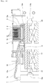
- Fig. 3 is an enlarged cross-sectional front view showing an operating state of an embodiment of the adhesive application device of the present invention.
- the adhesive container 8, the lift pins 9 and the rectangular container 11 can be raised and lowered by rotating a knob 10a of the first elevating device 10, as shown in Fig. 3 .
- the slide block unit held in the rectangular container 11 comprises a first slide block 12a positioned on the upper side of the unit and a second slide block 12b positioned on the lower side of the unit.
- the second slide block 12b positioned on the lower side of the unit is connected to a slide piece 13, which is connected to a rod 14.
- the rod 14 can be advanced and retracted in the cylinder 15.
- the advancement and retraction of the rod 14 in the cylinder 15 can be achieved by supplying compressed air at an appropriate pressure from a pneumatic pressure source to the opening 15a or supplying a pressure oil at an appropriate pressure from a hydraulic pressure source to the opening 15a.
- the numeral 16 denotes a second elevating device for raising and lowering the cylinder 15 to align the vertical position of the lower surface of the cylinder 15 and the lower surface of the second slide block 12b.
- the alignment of the vertical position of the lower surface of the cylinder 15 and the lower surface of the second slide block 12b can be achieved by raising or lowering the cylinder 15 by rotating the knob 16a.
- the first slide block 12a ascends a slope 17, on which the first slide block 12a is in contact with the second slide block 12b.
- the lift pins 9 supported by the first slide block 12a are raised, which raises the thin steel strip 2.
- the lift pins 9 can raise and lower the position of the thin steel strip 2 without moving the position of the adhesive container 8.
- the numeral 18 denotes dispense nozzles for dispensing the adhesive.
- the dispense nozzles 18 are disposed inside the adhesive container 8 to be spaced apart from the end face of the adhesive container 8 as shown in Figs. 3 , 4 and 5 .
- the adhesive dispense unit that accommodates the dispense nozzles 18 is fixed to the adhesive container 8.
- the number of the dispense nozzles 18 is six in this embodiment, but needless to say, is not limited thereto.
- the adhesive stored in the tank 7 can be supplied through the hose 7a to an adhesive pool 19 at a predetermined pressure, and can be stably dispensed from the six dispense nozzles 18 in an equal quantity.
- the six dispense nozzles 18 communicate with the adhesive pool 19.
- the numeral 20 denotes an electric heater for heating the adhesive to a predetermined temperature.
- the electric heater is connected with a power source (not shown in the figure) and is disposed in the inner periphery of the adhesive container 8 so as to surround the dispense nozzles 18.
- the fluidity of the adhesive in the adhesive container 8 can be enhanced and the adhesive can be stably dispensed from the dispense nozzles 18. Since the adhesive container 8 is located outside the die apparatus 6, the temperature rise by the electric heater 20 has no influence on the die apparatus, and simultaneously, temperature changes in the die apparatus have no influence on the fluidity of the adhesive.
- the thin steel strip 2 is drawn from the coil 1, then an adhesive is applied to the thin steel strip 2 with the adhesive application device 3, and the thin steel strip 2 is punched into a predetermined shape in the die apparatus 6, as shown in Fig. 1 . This process will be described in detail below.
- the adhesive is not continuously applied to the thin steel strip 2, but is rather applied to the thin steel strip 2 in synchronization with the timing of punching of the thin steel strip 2 into a predetermined shape by lowering the upper die 4 toward the lower die 5 in the configuration as shown Fig. 1 .
- a predetermined distance (about several millimeters) is provided between the thin steel strip 2 and the upper surface of the adhesive container 8, which is at the same height as the tops of the lift pins 9.
- the thin steel strip 2 is pressed downward to the lower die 5, and the lower surface of the thin steel strip 2 is brought into abutment with the upper surface of the adhesive container 8, as shown in Figs. 4 and 7 .
- the adhesive stored in the tank 7 is supplied through the hose 7a to adhesive pool 19 at a predetermined pressure, and is constantly dispensed from the dispense nozzles 18.
- the vertical distance between the upper surface of the adhesive container 8 and the tips of dispense nozzles 18 is constant, and at the time of the punching, the distance between the tips of the dispense nozzles 18 and the lower surface of the thin steel strip 2 that is brought into abutment with the upper surface of the adhesive container 8 is also constant. Due to this configuration, the amount of the adhesive that rises on the dispense nozzles 18 is substantially constant. In this manner, a substantially constant amount of the adhesive is applied to the lower surface of the thin steel strip 2.
- the thin steel strip 2 is punched into core sheets with a predetermined shape.
- the produced core sheets are stacked together within the lower die 5.
- the stacked core sheets are dispensed from the lower die 5 to give a laminated core.
- the laminated core dispensed from the lower die 5 is subjected to a given post-treatment such as heating, and used for assembly of electric parts.
- the adhesive is applied to the lower surface of the thin steel strip 2, and therefore care should be taken to prevent the application of the adhesive to the core sheet to be positioned at the bottom of the stacked core sheets of a predetermined number in a single lot dispensed from the lower die 5.
- the configuration as shown in Fig. 5 is employed in which, when the rod 14 is advanced in the cylinder 15 to pull the second slide block 12b to the left-hand side in the figure, the first slide block 12a ascends the slope 17, on which the first slide block 12a is in contact with the second slide block 12b.
- the lift pins 9 supported by the first slide block 12a are raised, which raises the thin steel strip 2. Consequently, the distance between the lower surface of the thin steel strip 2 and the tips of the dispense nozzles 18 becomes greater than that shown in Fig.
- the rod 14 is moved to the right-hand side in the figure so as to retract from the cylinder 15.
- the second slide block 12b is then pushed by the rod 14 to the right-hand side in the figure, and the first slide block 12a descends the slope 17, on which the first slide block 12a is in contact with the second slide block 12b.
- the adhesive application device is returned to the original position where the distance between the thin steel strip 2 and the upper surface of the adhesive container 8, which is at the same height as the tops of lift pins 9, is set at a predetermined value, as shown in Fig. 3 .
- the knob 10a is rotated to raise or lower the adhesive container 8 together with the lift pins 9 and the rectangular container 11 by an appropriate distance, so that the lower surface of the thin steel strip 2 is brought into abutment with the upper surface of the adhesive container 8 as shown in Fig. 4 to successfully apply the adhesive dispensed from the dispense nozzles 18 to the lower surface of the thin steel strip 2 in synchronization with the timing of punching of the thin steel strip 2.
- a height adjustment plate can also be used to raise or lower the adhesive container 8 together with the lift pins 9 and the rectangular container 11 by an appropriate distance.
- the lift pins 9 are raised to raise the thin steel strip 2 as shown in Fig. 5 , thereby preventing the application of the adhesive that rises on the dispense nozzles 18 to the lower surface of the thin steel strip 2. Accordingly, to successfully perform the movement as described in paragraph [0024] above in WO 2019/168022 , the knob 16a is rotated to raise or lower the cylinder 15 to align the vertical position of the lower surface of the cylinder 15 and the lower surface of the second slide block 12b.
- a feature of the present invention is that the distance between the lower surface of the thin steel strip and the tips of the adhesive dispense nozzles is kept constant at the timing of punching of the thin steel strip. This distance is kept constant without the fear of wear, shifting or other problems over time. This feature will be described below.
- the adhesive dispense unit is fixed to the adhesive container, and the adhesive dispense nozzles are disposed inside the adhesive container to be spaced apart from the end face of the adhesive container, and the device comprises a means capable of raising and lowering the thin steel strip without raising or lowering the adhesive container.
- the dispense nozzles (that are disposed inside the adhesive container to be spaced apart from the end face of the adhesive container) are located at a constant distance from the surface of the thin steel strip that is brought into abutment with the end face of the adhesive container, and thus a substantially constant amount of the adhesive dispensed from the dispense nozzles is applied to the thin steel strip when the thin steel strip is brought into abutment with the adhesive container, in synchronization with the timing of punching the thin steel strip into a predetermined shape. Simultaneously, care should be taken to prevent the application of an unnecessary adhesive to the thin steel strip, as described in paragraph [0028] above in WO 2019/168022 .
- the device is provided with a means capable of raising and lowering the thin steel strip without raising or lowering the adhesive container, as described in paragraph [0024] above in WO 2019/168022 . Due to this means, the thin steel strip is able to be raised or lowered without raising or lowering the adhesive container to prevent the application of an unnecessary adhesive to the thin steel strip.
- two separate functions are provided as an important feature of the invention: one is the function of keeping a constant distance between the tips of the adhesive dispense nozzles and the surface of the thin steel strip when the adhesive is applied to the thin steel strip; and the other is the function of moving the thin steel strip away from the adhesive dispense nozzles to prevent the application of the adhesive to the thin steel strip.
- the adhesive application device has no movable parts that may cause wear between the dispense nozzles 18 and the upper surface of the adhesive container 8, which has the function of keeping a constant distance between the tips of the dispense nozzles 18 and the lower surface of the thin steel strip 2. Due to this configuration, the distance between the tips of the adhesive dispense nozzles 18 and the lower surface of the thin steel strip 2 at the timing of punching of the thin steel strip 2 is kept constant without the fear of wear, shifting or other problems over time.
- the thin steel strip cannot be easily raised or lowered because the movement of the thin steel strip is restricted by other various parts or devices in the die apparatus.
- the adhesive application device of the present invention is applicable to the production of laminated cores for stepper motors or motor cores.
Landscapes
- Engineering & Computer Science (AREA)
- Power Engineering (AREA)
- Life Sciences & Earth Sciences (AREA)
- Wood Science & Technology (AREA)
- Manufacturing & Machinery (AREA)
- Manufacturing Cores, Coils, And Magnets (AREA)
- Manufacture Of Motors, Generators (AREA)
- Coating Apparatus (AREA)
- Application Of Or Painting With Fluid Materials (AREA)
Applications Claiming Priority (3)
| Application Number | Priority Date | Filing Date | Title |
|---|---|---|---|
| JP2018037679 | 2018-03-02 | ||
| JP2018188477A JP6515241B1 (ja) | 2018-03-02 | 2018-10-03 | 接着剤塗布装置及び接着剤塗布方法 |
| PCT/JP2019/007538 WO2019168022A1 (fr) | 2018-03-02 | 2019-02-27 | Dispositif et procédé de revêtement d'adhésif |
Publications (2)
| Publication Number | Publication Date |
|---|---|
| EP3780363A1 true EP3780363A1 (fr) | 2021-02-17 |
| EP3780363A4 EP3780363A4 (fr) | 2022-02-09 |
Family
ID=66530763
Family Applications (1)
| Application Number | Title | Priority Date | Filing Date |
|---|---|---|---|
| EP19759989.7A Withdrawn EP3780363A4 (fr) | 2018-03-02 | 2019-02-27 | Dispositif et procédé de revêtement d'adhésif |
Country Status (6)
| Country | Link |
|---|---|
| US (1) | US10953427B2 (fr) |
| EP (1) | EP3780363A4 (fr) |
| JP (1) | JP6515241B1 (fr) |
| KR (1) | KR102169906B1 (fr) |
| CN (1) | CN110741541B (fr) |
| WO (1) | WO2019168022A1 (fr) |
Families Citing this family (5)
| Publication number | Priority date | Publication date | Assignee | Title |
|---|---|---|---|---|
| JP6856794B1 (ja) * | 2020-03-12 | 2021-04-14 | 田中精密工業株式会社 | 接着剤塗付設備 |
| CN111715475A (zh) * | 2020-06-11 | 2020-09-29 | 浙江明都创芯电器有限公司 | 一种led自动真空点胶机构 |
| JP7059472B1 (ja) * | 2020-12-09 | 2022-04-26 | 田中精密工業株式会社 | 積層鉄心の加熱装置 |
| JP6894616B1 (ja) * | 2020-12-25 | 2021-06-30 | 田中精密工業株式会社 | 積層鉄心の加熱装置 |
| JP7634852B2 (ja) * | 2023-02-14 | 2025-02-25 | 大垣精工株式会社 | 接着剤付与装置、及び鋼板接着方法 |
Family Cites Families (20)
| Publication number | Priority date | Publication date | Assignee | Title |
|---|---|---|---|---|
| US4522875A (en) * | 1983-09-30 | 1985-06-11 | Phillips Petroleum Company | Stampable sheets of bonded laminate of metal sheet and fiber mat reinforced poly(arylene sulfide) and method of preparation using radio frequency energy |
| DE59009841D1 (de) | 1990-11-09 | 1995-12-07 | Siemens Ag | MOSFET-Schalter für eine induktive Last. |
| JPH05304037A (ja) * | 1992-04-28 | 1993-11-16 | Aida Eng Ltd | 積層コアの製造方法 |
| US5576460A (en) | 1994-07-27 | 1996-11-19 | Massachusetts Institute Of Technology | Preparation of arylamines |
| US5890476A (en) | 1996-08-07 | 1999-04-06 | Grant; Barry | Fuel delivery nozzle |
| JP2001025218A (ja) | 1999-07-09 | 2001-01-26 | Mitsui High Tec Inc | 積層鉄心製造金型装置 |
| JP3822020B2 (ja) * | 2000-05-16 | 2006-09-13 | 株式会社コアテック | 積層コアの製造装置 |
| JP2003033711A (ja) | 2001-07-25 | 2003-02-04 | Koatekku:Kk | 接着剤塗布装置及び接着剤塗布方法 |
| JP5160862B2 (ja) * | 2007-11-13 | 2013-03-13 | 黒田精工株式会社 | 積層鉄心の製造装置 |
| JP5155423B2 (ja) * | 2011-04-04 | 2013-03-06 | ファナック株式会社 | かご形回転子及びその製造方法 |
| JP5576460B2 (ja) | 2012-11-22 | 2014-08-20 | 黒田精工株式会社 | 積層鉄心の製造装置 |
| AT512931B1 (de) * | 2012-12-11 | 2013-12-15 | Voestalpine Stahl Gmbh | Blechpaket und Verfahren zum Verbinden von Blechteilen zu einem Blechpaket |
| WO2015030168A1 (fr) * | 2013-08-30 | 2015-03-05 | 武蔵エンジニアリング株式会社 | Procédé et dispositif de fabrication d'un article stratifié en forme de plaque |
| JP6396064B2 (ja) | 2014-04-08 | 2018-09-26 | 兵神装備株式会社 | 多層製品製造装置、及び多層製品の製造方法 |
| KR101599291B1 (ko) | 2014-05-28 | 2016-03-14 | 주식회사 포스코티엠씨 | 접착식 적층 코어부재 제조장치 및 접착제 도포유닛 |
| JP5890476B2 (ja) | 2014-07-02 | 2016-03-22 | 黒田精工株式会社 | 積層鉄心の製造装置および製造方法 |
| KR101616987B1 (ko) * | 2014-07-08 | 2016-04-29 | 주식회사 포스코티엠씨 | 고주파 가열을 이용한 접착식 적층 코어부재 제조장치 및 이를 위한 라미네이트 유닛 |
| KR101618709B1 (ko) * | 2014-07-09 | 2016-05-09 | 주식회사 포스코티엠씨 | 접착식 적층 코어부재 제조용 라미네이트 유닛 및 이를 갖는 적층 코어부재 제조장치 |
| JP6256265B2 (ja) * | 2014-09-05 | 2018-01-10 | Jfeスチール株式会社 | スラリー塗布装置およびスラリー塗布方法 |
| CN106716796B (zh) * | 2014-11-07 | 2020-02-21 | 黑田精工株式会社 | 层叠铁芯的制造装置和层叠铁芯的制造方法 |
-
2018
- 2018-10-03 JP JP2018188477A patent/JP6515241B1/ja active Active
-
2019
- 2019-02-27 WO PCT/JP2019/007538 patent/WO2019168022A1/fr not_active Ceased
- 2019-02-27 KR KR1020207027808A patent/KR102169906B1/ko not_active Expired - Fee Related
- 2019-02-27 EP EP19759989.7A patent/EP3780363A4/fr not_active Withdrawn
- 2019-02-27 CN CN201980002949.6A patent/CN110741541B/zh active Active
- 2019-02-27 US US16/977,140 patent/US10953427B2/en not_active Expired - Fee Related
Also Published As
| Publication number | Publication date |
|---|---|
| KR102169906B1 (ko) | 2020-10-26 |
| WO2019168022A1 (fr) | 2019-09-06 |
| JP2019150813A (ja) | 2019-09-12 |
| KR20200118215A (ko) | 2020-10-14 |
| CN110741541B (zh) | 2020-08-07 |
| US10953427B2 (en) | 2021-03-23 |
| EP3780363A4 (fr) | 2022-02-09 |
| US20210031227A1 (en) | 2021-02-04 |
| JP6515241B1 (ja) | 2019-05-15 |
| CN110741541A (zh) | 2020-01-31 |
Similar Documents
| Publication | Publication Date | Title |
|---|---|---|
| US10953427B2 (en) | Adhesive application device and adhesive application method | |
| US10666119B2 (en) | Laminate unit for manufacturing bonded-type laminated core member and apparatus having the same for manufacturing laminated core member | |
| US10350868B2 (en) | Apparatus for manufacturing bonded-type laminated core member using high-frequency heating and laminate unit for the same | |
| KR101599291B1 (ko) | 접착식 적층 코어부재 제조장치 및 접착제 도포유닛 | |
| TWI762032B (zh) | 層積鐵芯之製造裝置及其製造方法 | |
| KR101618708B1 (ko) | 접착식 적층 코어부재 제조장치 및 온도제어방법 | |
| KR101604988B1 (ko) | 접착식 적층 코어부재 제조장치 및 이에 적용되는 적층 코어부재 이송용 정렬장치 | |
| CN107534366B (zh) | 粘合式层叠铁芯制造装置 | |
| JP6178443B2 (ja) | 積層鉄心の製造装置 | |
| JP2009291059A (ja) | 積層鉄心の製造装置及び製造方法 | |
| US20250373129A1 (en) | Method and device for producing laminated cores from laminations | |
| JP7292453B1 (ja) | 接着剤塗布設備 | |
| KR101729286B1 (ko) | 접착식 적층 코어 제조장치 | |
| EP4096074A1 (fr) | Dispositif de revêtement adhésif, dispositif de fabrication de noyau de fer stratifié comprenant ledit dispositif de revêtement adhésif et procédé de fabrication de noyau de fer stratifié | |
| KR101570381B1 (ko) | 채널 도관을 갖는 접착제 도포유닛 및 접착식 적층 코어부재 제조장치 | |
| US11819875B2 (en) | Adhesive application system |
Legal Events
| Date | Code | Title | Description |
|---|---|---|---|
| STAA | Information on the status of an ep patent application or granted ep patent |
Free format text: STATUS: THE INTERNATIONAL PUBLICATION HAS BEEN MADE |
|
| PUAI | Public reference made under article 153(3) epc to a published international application that has entered the european phase |
Free format text: ORIGINAL CODE: 0009012 |
|
| STAA | Information on the status of an ep patent application or granted ep patent |
Free format text: STATUS: REQUEST FOR EXAMINATION WAS MADE |
|
| 17P | Request for examination filed |
Effective date: 20201207 |
|
| AK | Designated contracting states |
Kind code of ref document: A1 Designated state(s): AL AT BE BG CH CY CZ DE DK EE ES FI FR GB GR HR HU IE IS IT LI LT LU LV MC MK MT NL NO PL PT RO RS SE SI SK SM TR |
|
| AX | Request for extension of the european patent |
Extension state: BA ME |
|
| DAV | Request for validation of the european patent (deleted) | ||
| DAX | Request for extension of the european patent (deleted) | ||
| A4 | Supplementary search report drawn up and despatched |
Effective date: 20220112 |
|
| RIC1 | Information provided on ipc code assigned before grant |
Ipc: B05D 7/14 20060101ALN20220105BHEP Ipc: B05D 3/12 20060101ALN20220105BHEP Ipc: B05D 3/00 20060101ALN20220105BHEP Ipc: B05C 11/10 20060101ALN20220105BHEP Ipc: B05C 5/02 20060101ALN20220105BHEP Ipc: B05C 5/00 20060101ALN20220105BHEP Ipc: H02K 15/02 20060101ALI20220105BHEP Ipc: H01F 41/02 20060101ALI20220105BHEP Ipc: B32B 37/12 20060101ALI20220105BHEP Ipc: B05D 5/10 20060101ALI20220105BHEP Ipc: B05D 1/26 20060101AFI20220105BHEP |
|
| RAP3 | Party data changed (applicant data changed or rights of an application transferred) |
Owner name: TANAKA SEIMITSU KOGYO CO., LTD. |
|
| REG | Reference to a national code |
Ref country code: DE Ref legal event code: R079 Free format text: PREVIOUS MAIN CLASS: H02K0015020000 Ipc: B05D0001260000 |
|
| GRAP | Despatch of communication of intention to grant a patent |
Free format text: ORIGINAL CODE: EPIDOSNIGR1 |
|
| STAA | Information on the status of an ep patent application or granted ep patent |
Free format text: STATUS: GRANT OF PATENT IS INTENDED |
|
| RIC1 | Information provided on ipc code assigned before grant |
Ipc: B05D 7/14 19740701ALN20221230BHEP Ipc: B05D 3/12 19740701ALN20221230BHEP Ipc: B05D 3/00 19740701ALN20221230BHEP Ipc: B05C 11/10 19680901ALN20221230BHEP Ipc: B05C 5/02 19680901ALN20221230BHEP Ipc: B05C 5/00 19680901ALN20221230BHEP Ipc: H02K 15/02 19680901ALI20221230BHEP Ipc: H01F 41/02 19680901ALI20221230BHEP Ipc: B32B 37/12 20060101ALI20221230BHEP Ipc: B05D 5/10 19740701ALI20221230BHEP Ipc: B05D 1/26 19740701AFI20221230BHEP |
|
| INTG | Intention to grant announced |
Effective date: 20230130 |
|
| RIN1 | Information on inventor provided before grant (corrected) |
Inventor name: KUROSAKI, EIICHI |
|
| STAA | Information on the status of an ep patent application or granted ep patent |
Free format text: STATUS: THE APPLICATION IS DEEMED TO BE WITHDRAWN |
|
| 18D | Application deemed to be withdrawn |
Effective date: 20230610 |