EP3780747B1 - Auswahl des access point auf basis des backhaul-status - Google Patents
Auswahl des access point auf basis des backhaul-status Download PDFInfo
- Publication number
- EP3780747B1 EP3780747B1 EP19781967.5A EP19781967A EP3780747B1 EP 3780747 B1 EP3780747 B1 EP 3780747B1 EP 19781967 A EP19781967 A EP 19781967A EP 3780747 B1 EP3780747 B1 EP 3780747B1
- Authority
- EP
- European Patent Office
- Prior art keywords
- backhaul
- access point
- wireless communication
- section
- wireless
- Prior art date
- Legal status (The legal status is an assumption and is not a legal conclusion. Google has not performed a legal analysis and makes no representation as to the accuracy of the status listed.)
- Active
Links
Images




Classifications
-
- H—ELECTRICITY
- H04—ELECTRIC COMMUNICATION TECHNIQUE
- H04W—WIRELESS COMMUNICATION NETWORKS
- H04W48/00—Access restriction; Network selection; Access point selection
- H04W48/08—Access restriction or access information delivery, e.g. discovery data delivery
- H04W48/10—Access restriction or access information delivery, e.g. discovery data delivery using broadcasted information
-
- H—ELECTRICITY
- H04—ELECTRIC COMMUNICATION TECHNIQUE
- H04W—WIRELESS COMMUNICATION NETWORKS
- H04W48/00—Access restriction; Network selection; Access point selection
- H04W48/16—Discovering, processing access restriction or access information
-
- H—ELECTRICITY
- H04—ELECTRIC COMMUNICATION TECHNIQUE
- H04W—WIRELESS COMMUNICATION NETWORKS
- H04W52/00—Power management, e.g. Transmission Power Control [TPC] or power classes
- H04W52/04—Transmission power control [TPC]
- H04W52/38—TPC being performed in particular situations
- H04W52/46—TPC being performed in particular situations in multi-hop networks, e.g. wireless relay networks
-
- H—ELECTRICITY
- H04—ELECTRIC COMMUNICATION TECHNIQUE
- H04W—WIRELESS COMMUNICATION NETWORKS
- H04W48/00—Access restriction; Network selection; Access point selection
- H04W48/18—Selecting a network or a communication service
-
- H—ELECTRICITY
- H04—ELECTRIC COMMUNICATION TECHNIQUE
- H04W—WIRELESS COMMUNICATION NETWORKS
- H04W84/00—Network topologies
- H04W84/02—Hierarchically pre-organised networks, e.g. paging networks, cellular networks, WLAN [Wireless Local Area Network] or WLL [Wireless Local Loop]
- H04W84/10—Small scale networks; Flat hierarchical networks
- H04W84/12—WLAN [Wireless Local Area Networks]
-
- H—ELECTRICITY
- H04—ELECTRIC COMMUNICATION TECHNIQUE
- H04W—WIRELESS COMMUNICATION NETWORKS
- H04W92/00—Interfaces specially adapted for wireless communication networks
- H04W92/16—Interfaces between hierarchically similar devices
- H04W92/20—Interfaces between hierarchically similar devices between access points
Definitions
- the present technology relates to wireless communication apparatus and a wireless communication method. More particularly, the technology relates to wireless communication apparatus and a wireless communication method used advantageously to perform wireless communication by employing a plurality of wireless base stations (access points) and a wireless terminal station.
- frequency band information including quality indicator information covering path loss, load, throughput, capacitance, and backhaul with respect to each frequency band is broadcast by beacon frame. It has also been disclosed that the multi-band WTRU selects a multi-band AP and a frequency band to associate with on the basis of the frequency band information (e.g., see PTL 1).
- PTL 2 discloses a method and apparatus for identifying an access point for selection by an access terminal, wherein the AP for selection by the AT is identified by the one or more APs based at least on the load information and RSSI values generated at the one or more APs.
- the above-cited PTL 1 does not specify, for example, what the backhaul information included in the quality indicator information contains or how an appropriate multi-band AP is selected on the basis of the backhaul information.
- the present technology has been devised in view of the above circumstances and aims at allowing a wireless terminal station to easily select an appropriate connection destination from among a plurality of wireless base stations.
- a wireless terminal station is enabled to easily select an appropriate connection destination from among a plurality of wireless base stations.
- the present technology involves, for a wireless communication system in accordance with the IEEE 802.11 (wireless LAN) standard, for example, allowing a plurality of wireless base stations to communicate with each other and enabling a wireless terminal station to select an appropriate connection destination from among a plurality of the wireless base stations in such a manner as to maximize the utilization efficiency of frequency resources.
- IEEE 802.11 wireless LAN
- the wireless base station will be referred to as the access point (AP) and the wireless terminal station as the station (STA).
- AP access point
- STA station
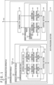
- FIG. 1 is a block diagram depicting a configuration example of a wireless communication apparatus 101 to which the present technology is applied.
- the wireless communication apparatus 101 functions as an access point that connects to a trunk line communication network (not depicted) such as the Internet via a wired backhaul 102.
- the wireless communication apparatus 101 communicates with other servers (not depicted) via the backhaul 102 and the trunk line communication network, and performs wireless communication with another access point and another station.
- the wireless communication apparatus 101 includes a communication module 111 and a data processing section 112.
- the communication module 111 connects to the trunk line communication network via the backhaul 102, and communicates with servers via the backhaul 102 and the trunk line communication network.
- the communication module 111 also communicates wirelessly with another access point and another station.
- the communication module 111 includes an antenna 121, a wireless communication module 122, a wired communication module 123, and a connection terminal 124.
- the antenna 121 wirelessly transmits various signals supplied from the wireless communication module 122. Further, the antenna 121 receives wirelessly transmitted signals and sends the received signals to the wireless communication module 122.
- the wireless communication module 122 includes a semiconductor chip, for example. While exchanging information with the data processing section 112 as needed, the wireless communication module 122 sends various signals to the antenna 121 to have the signals transmitted from the antenna 121, and performs the processes corresponding to the signals received by the antenna 121.
- the wireless communication module 122 includes a communication section 131 and a control section 132.
- the communication section 131 Under control of the control section 132, the communication section 131 communicates wirelessly with another access point and another station via the antenna 121.
- the control section 132 controls the operation of the wireless communication module 122 as a whole.
- the control section 132 supplies the data processing section 112 with the signal sent from the communication section 131, and supplies the communication section 131 with the information sent from the data processing section 112.
- the control section 132 controls the communication section 131 (an RF transmission section 147 therein) to regulate the intensity of signals transmitted from the antenna 121.
- the communication section 131 includes an antenna sharing section 141, an RF reception section 142, a digital signal conversion section 143, a signal reception section 144, a signal generation section 145, an analog signal conversion section 146, and the RF transmission section 147.
- the antenna sharing section 141 is a switch that performs a switching between transmission and reception. That is, the antenna sharing section 141 supplies the antenna 121 with signals sent from the RF transmission section 147, and supplies the RF reception section 142 with signals sent from the antenna 121.
- the RF reception section 142 includes a low-noise amplifier, an AGC (Auto Gain Control) section, a frequency converter, and a filter, for example.
- the RF reception section 142 receives signals from the antenna 121 via the antenna sharing section 141.
- the RF reception section 142 then performs various processes such as amplification, gain adjustment, frequency conversion, and filtering on the received signal as needed, and sends the signal resulting from the processing to the digital signal conversion section 143.
- the RF reception section 142 obtains the reception intensity of the received signal as needed and sends what is obtained to the control section 132.
- the digital signal conversion section 143 subjects the signal supplied from the RF reception section 142 to AD (Analog Digital) conversion for conversion from analog to digital form, and sends the converted signal to the signal reception section 144.
- AD Analog Digital
- the signal reception section 144 Under control of the control section 132, the signal reception section 144 performs various processes such as demodulation and decoding on the signal supplied from the digital signal conversion section 143, and sends the signal resulting from the processing to the control section 132.
- the signal generation section 145 performs an encoding process on the basis of information supplied from the control section 132 to generate a signal in a predetermined format, carries out a modulation process on the generated signal, and sends the modulated signal to the analog signal conversion section 146.
- the analog signal conversion section 146 subjects the signal supplied from the signal generation section 145 to DA (Digital Analog) conversion for conversion from digital to analog form, and sends the converted signal to the RF transmission section 147.
- DA Digital Analog
- the RF transmission section 147 includes a frequency converter, an amplifier, and a filter, for example.
- the RF transmission section 147 performs such processes as frequency conversion, amplification, and filtering on the signal supplied from the analog signal conversion section 146.
- the RF transmission section 147 sends the processed signal to the antenna 121 via the antenna sharing section 141 to have the signal transmitted from the antenna 121.
- the wired communication module 123 includes a semiconductor chip, for example.
- the wired communication module 123 connects to the trunk line communication network via the connection terminal 124 and the backhaul 102. While exchanging information with the data processing section 112 as needed, the wired communication module 123 transmits various signals to servers via the connection terminal 124, the backhaul 102, and the trunk line communication network, and performs the processes corresponding to the signals received from the servers.
- the wired communication module 123 includes a communication section 151 and a control section 152.
- the communication section 151 Under control of the control section 152, the communication section 151 connects to the trunk line communication network via the connection terminal 124 and the backhaul 102, and communicates with the servers via the trunk line communication network.
- the control section 152 controls the operation of the wired communication module 123 as a whole. Also, the control section 152 supplies the data processing section 112 with the signal sent from the communication section 151, and supplies the communication section 151 with the information sent from the data processing section 112.
- the communication section 151 includes a digital signal conversion section 161, a signal reception section 162, a signal generation section 163, and an analog signal conversion section 164.
- the digital signal conversion section 161 subjects the signal received via the backhaul 102 and the connection terminal 124 to AD (Analog Digital) conversion for conversion from analog to digital form, and sends the converted signal to the signal reception section 162.
- AD Analog Digital
- the signal reception section 162 Under control of the control section 152, the signal reception section 162 performs various processes such as demodulation and decoding on the signal supplied from the digital signal conversion section 153, and sends the signal resulting from the processing to the control section 152.
- the signal generation section 163 performs an encoding process on the basis of information supplied from the control section 152 to generate a signal in a predetermined format, performs a modulation process on the signal thus generated, and sends the modulated signal to the analog signal conversion section 164.
- the analog signal conversion section 164 subjects the signal supplied from the signal generation section 163 to DA (Digital Analog) conversion for conversion from digital to analog form, and outputs the converted signal to the backhaul 102 via the connection terminal 124.
- DA Digital Analog
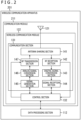
- FIG. 2 is a block diagram depicting a configuration example of a wireless communication apparatus 201 to which the present technology is applied.
- the components corresponding to those of the wireless communication apparatus 101 in FIG. 1 are designated by like reference numerals, and explanation of the corresponding components is omitted hereunder where appropriate.
- the wireless communication apparatus 201 functions as an access point that connects to the trunk line communication network via another access point and the backhaul 102. Also, the wireless communication apparatus 201 communicates wirelessly with another access point and another station.
- the wireless communication apparatus 201 is configured such that the wired communication module 123 and the connection terminal 124 are removed from the wireless communication apparatus 101.
- the wireless communication apparatus 201 is different from the wireless communication apparatus 101 in that a communication module 211 is provided to replace the communication module 111.
- the communication module 211 is different from the communication module 111 in that the wired communication module 123 and the connection terminal 124 are removed.
- the wireless communication apparatus 201 is connected with a wirelessly operating backhaul (referred to as the wireless backhaul hereunder) for connection to a wire-based backhaul (referred to as the wired backhaul hereunder) via another access point (the wireless communication apparatus 101).
- a wirelessly operating backhaul referred to as the wireless backhaul hereunder
- a wire-based backhaul referred to as the wired backhaul hereunder
- the access point connected directly with the wired backhaul like the wireless communication apparatus 101 will be referred to as the direct access point.
- the access point connected with the wireless backhaul like the wireless communication apparatus 201 for connection to the wired backhaul via another access point will be referred to as the indirect access point.
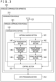
- FIG. 3 is a block diagram depicting a configuration example of a wireless communication apparatus 301 to which the present technology is applied.
- the components corresponding to those of the wireless communication apparatus 201 in FIG. 2 are designated by like reference numerals, and explanation of the corresponding components is omitted hereunder where appropriate.
- the wireless communication apparatus 301 functions as a station that communicates wirelessly with access points.
- the wireless communication apparatus 301 includes a communication module 311 and a data processing section 312.
- the communication module 311 communicates wirelessly with access points.
- the communication module 311 includes a wireless communication module 321 in place of the wireless communication module 122.
- the wireless communication module 321 includes a semiconductor chip, for example. While exchanging information with the data processing section 312 as needed, the wireless communication module 321 sends various signals to the antenna 121 to have the signals transmitted from the antenna 121, and performs the processes corresponding to the signals received by the antenna 121.
- the wireless communication module 321 includes a control section 331 in place of the control section 132.
- the control section 331 controls the operation of the wireless communication module 321 as a whole.
- the control section 331 supplies the data processing section 312 with the signal sent from the communication section 131, and supplies the communication section 131 with the information sent from the data processing section 312.
- the control section 331 controls the communication section 131 (RF transmission section 147 therein) to regulate the intensity of signals transmitted from the antenna 121.
- the control section 331 selects the access point to which the wireless communication apparatus 301 is connected.
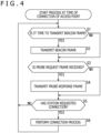
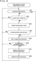
- step S1 the control section 132 determines whether or not it is time to transmit a Beacon frame. For example, each access point transmits a Beacon frame as a broadcast signal periodically at predetermined intervals. In the case where the control section 132 determines that it is time to transmit a Beacon frame, the process is transferred to step S2.
- step S2 the access point transmits the Beacon frame.
- control section 132 supplies the signal generation section 145 with information to be stored in each field in the Beacon frame, and orders the signal generation section 145 to generate the Beacon frame.
- the signal generation section 145 On the basis of the information supplied from the control section 132, the signal generation section 145 generates the Beacon frame.
- the signal generation section 145 sends the generated Beacon frame to the RF transmission section 147 via the analog signal conversion section 146.
- the RF transmission section 147 transmits the Beacon frame via the antenna sharing section 141 and the antenna 121.
- FIG. 6 depicts an example of a Beacon frame format.
- the Beacon frame includes a Frame Type field, a Duration field, a Receiver Address field, a Transmitter Address field, a Beacon body field, and an FCS (Frame Check Sequence) field.
- a Frame Type field a Duration field
- a Receiver Address field a Receiver Address field
- a Transmitter Address field a Beacon body field
- FCS Full Check Sequence
- the Frame Type field includes a field in which information indicative of the type of the frame is set.
- the information indicative of the Beacon frame is set in this field.
- the Duration field includes a field in which information indicative of the duration of a frame transmission period is set.
- the Receiver Address field includes a field in which the address of another access point or another station that receives a frame (e.g., MAC address) is set. Since the Beacon frame is broadcast without specifying a receiver, a broadcast address is set in this field.
- a frame e.g., MAC address
- the Transmitter Address field includes a field in which the address of the access point or the station (e.g., MAC address) that transmits the frame is set.
- the address of the access point acting as the transmitter of the beacon frame is set in this field.
- the Beacon body field includes a field in which diverse information transmitted by the Beacon frame is set.
- the Beacon body field includes Network Cost Info, which is network connection information regarding the wireless communication system.
- the Network Cost Info includes information regarding frequency resources (media) of the access point.
- the Network Cost Info includes a Backhaul Type and Channel Occupancy Info.
- the Backhaul Type is information indicative of the state of connection of the access point to the backhaul (backhaul connection information).
- the Backhaul Type includes the type of the backhaul and the number of hops (hop num) for the access point.
- the type of the backhaul is set to either Wire or Wireless.
- the type of the backhaul is set to Wire.
- the type of the backhaul is set to Wireless.
- the number of hops indicates the number of access points to pass through before the wired backhaul is connected. For example, the number of hops for the direct access point is set to 0.
- the indirect access point is connected to the wired backhaul by passing through other access points as described above.
- the number of access points to pass through before the wired backhaul is connected is set to the number of hops.
- the number of hops does not include the starting access point (i.e., access point for which the number of hops is set) but includes the access point connected to the wired backhaul (direct access point).
- the Channel Occupancy Info includes information indicating the state of use of media (frequency resources) available for the access point with regard to each sub-channel.
- the Channel Occupancy Info regarding each sub-channel includes an Occupying Channel ID, a Channel Bandwidth, and an Occupancy Ratio.
- the Occupying Channel ID is an ID that identifies each sub-channel.
- the Channel Bandwidth indicates the bandwidth of the frequency available for i.e., allocated to the sub-channels.
- the Channel Bandwidth may be omitted.
- the Occupancy Ratio indicates the ratio at which each sub-channel has been used.
- the Occupancy Ratio indicates the ratio of the time in which each sub-channel has been actually used (time in which signal transmission and reception have been performed using the sub-channel) with respect to an immediately preceding predetermined time period.
- FIG. 7 depicts an example of Occupancy Ratios of access points and sub-channels. Specifically, the left part of FIG. 7 indicates Occupancy Ratios of an access point AP1, and the right part of FIG. 7 depicts Occupancy Ratios of an access point AP2.
- the horizontal axis stands for time and the vertical axis for frequency.
- the bandwidth of the frequency available for the access points AP1 and AP2 is 40 MHz.
- the bandwidth is bisected into channels A and B with a bandwidth of 20 MHz each.
- Channel Bending also called Channel Aggregation
- the channels A and B may each be used singly, or the two sub-channels may be used in combination.
- the channel A alone is first used to transmit and receive packets before the channels A and B are combined to transmit packets.
- the channels A and B are combined to transmit, receive, and transmit packets, in that order.
- the Occupancy Ratio is 90% when viewed solely in the time axis direction.
- the Occupancy Ratio is 90% for the channel A
- the Occupancy Ratio is 15% for the channel B at the access point AP1.
- the Occupancy Ratio is 90% for both the channel A and the channel B at the access point AP1.
- the frequency resources of each access point are efficiently utilized.
- the Occupancy Ratio for the channel B at the access point A is found to be low, so that the channel B has capacity to spare (surplus capacity).
- the unoccupied time of the channel B at the access point A may be utilized profitably as spare frequency resources to increase the transmission amount of signals, boost the transmission rate of signals, and improve communication quality.
- the FCS field includes a field in which a Frame Check Sequence is set.
- step S2 in the case where it is determined in step S1 that it is not time to transmit a Beacon frame, the processing of step S2 is skipped and transferred to step S3.
- step S3 the control section 132 determines whether or not a Probe Request frame is received.
- the RF reception section 142 sends the received Probe Request frame to the control section 132 via the digital signal conversion section 143 and the signal reception section 144. This allows the control section 132 to determine that the Probe Request frame is received. The process is then transferred to step S4.
- step S4 the access point transmits a Probe Response frame.
- control section 132 supplies the signal generation section 145 with the information to be stored in each field of the Probe Response frame, and orders the signal generation section 145 to generate the Probe Response frame.
- the signal generation section 145 On the basis of the information supplied from the control section 132, the signal generation section 145 generates the Probe Response frame, and sends the generated Probe Response frame to the RF transmission section 147 via the analog signal conversion section 146.
- the Probe Response frame includes at least the Network Cost Info depicted in FIG. 6 .
- the Receiver Address field is set with the address of the station that transmits the Probe Request frame.
- the RF transmission section 147 transmits the Probe Response signal as a broadcast signal via the antenna sharing section 141 and the antenna 121.
- step S4 the processing of step S4 is skipped. The process is then transferred to step S5.
- step S5 the control section 132 determines whether or not the station has requested connection. In the case where it is determined that the station has not requested connection, the process is returned to step S1.
- steps S1 to S5 are repeated until it is determined in step S5 that the station has requested connection.
- the RF reception section 142 sends the received Authentication Request frame to the control section 132 via the digital signal conversion section 143 and the signal reception section 144. This allows the control section 132 to determine that the station has requested connection. The process is then transferred to step S6.
- step S6 the access point performs a connection process.
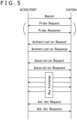
- the access point performs a connection process with the station that has requested connection in accordance with a protocol depicted in FIG. 5 .
- the access point upon receipt of the Authentication Request frame, the access point transmits an Authentication Response frame to the station.
- the access point then receives an Association Request frame from the station. In response to this, the access point transmits an Association Response frame to the station.
- the access point exchanges encryption keys with the station.
- the access point then receives an Ack Set Request frame from the station. In response to this, the access point transmits an Ack Set Response frame to the station.
- the access point establishes connection with the station.
- the access point then starts exchanging data with the station.
- step S51 the control section 331 determines whether or not a Beacon frame is received. In the case where it is determined that the Beacon frame is not received, the process is transferred to step S52.
- step S52 the control section 331 determines whether or not an access point is connected. In the case where it is determined that the access point is connected, the process is returned to step S51.
- steps S51 and S52 are repeated until the Beacon frame is determined to be received in step S51 or until the access point is determined to be not connected in step S52.
- step S52 determines whether access point is connected.
- step S53 the process is transferred to step S53. This, for example, is a case where the station is not connected with any access point and needs to search for a connectable access point because no Beacon frame has been received.
- step S53 the station transmits a Probe Request frame.
- control section 331 supplies the signal generation section 145 with the information to be stored in each field of the Probe Request frame, and orders the signal generation section 145 to generate the Probe Request frame.
- the signal generation section 145 On the basis of the information supplied from the control section 331, the signal generation section 145 generates the Probe Request frame.
- the signal generation section 145 sends the generated Probe Request frame to the RF transmission section 147 via the analog signal conversion section 146.
- a broadcast address is set to the receiver address.
- the RF transmission section 147 transmits the Probe Request frame via the antenna sharing section 141 and the antenna 121.
- step S54 the station determines whether or not the Probe Response frame is received. In the case where it is determined that the Probe Response frame is not received, the process is returned to step S51.
- steps S51 to S54 are repeated until the Beacon frame is determined to be received in step S51 or until the Probe Response frame is determined to be received in step S54.
- the RF reception section 142 sends the Probe Response frame to the control section 331 via the digital signal conversion section 143 and the signal reception section 144. This allows the control section 331 to determine that the Probe Response frame is received. The process is then transferred to step S55.
- the station receives Probe Response frames from a plurality of access points.
- step S2 in FIG. 4 In the case where the Beacon frame transmitted from the access point in the above-described step S2 in FIG. 4 is received via the antenna 121 and the antenna sharing section 141 in step S51, the RF reception section 142 sends the received Beacon frame to the control section 331 via the digital signal conversion section 143 and the signal reception section 144. This allows the control section 331 to determine that the Beacon frame is received. The processing of step S52 to S54 is then skipped, and the process is transferred to step S55.
- the station receives Beacon frames from a plurality of access points.
- step S55 the control section 331 selects a connection destination. Specifically, the control section 331 selects the connection destination from among connectable access points based on the Network Cost Info regarding each of these access points.
- the connectable access points include the access point having transmitted the Beacon frame received in the processing of step S51 and the access point having transmitted the Probe Response frame received in the processing of step S54. In the case where the station is being connected with an access point, this connected access point is also included in the connectable access points.
- control section 331 selects the connection destination from among the connectable access points in accordance with the following conditions.
- this access point is selected as the connection destination.
- connection destination is selected in accordance with the following Conditions 2.1 to 2.3.
- connection destination is selected in accordance with the following Conditions 2.1.1 to 2.1.2.
- the direct access point with a lower Occupancy Ratio than the other direct points is preferentially selected as the connection destination.
- the direct access point having the sub-channel with the lowest Occupancy Ratio is selected as the connection destination.
- the direct access point having the sub-channels with the lowest average Occupancy Ratio is selected as the connection destination.
- the direct access point with higher reception intensity of the Beacon frame or of the Probe Response frame than the other direct access points is preferentially selected as the connection destination.
- connection destination is selected in accordance with the following Conditions 2.2.1 and 2.2.2.
- a direct access point is preferentially selected over the indirect access points as the connection destination.
- connection destination is selected in accordance with the above-stated Conditions 2.1.1 and 2.1.2.
- connection destination is selected in accordance with the following Conditions 2.3.1 to 2.3.3.
- the indirect access point with a smaller number of hops than the other indirect access points is preferentially selected as the connection destination.
- the indirect access point with a lower Occupancy Ratio than the other indirect access points is preferentially selected as the connection destination.
- the indirect access point having the sub-channel with the lowest Occupancy Ratio is selected as the connection destination.
- the indirect access point having the sub-channels with the lowest average Occupancy Ratio is selected as the indirect access point.
- the indirect access point with higher reception intensity of the Beacon Frame or of the Probe Response frame than the other indirect access points is preferentially selected as the connection destination.
- step S56 the control section 331 determines whether or not the connection destination is changed. In the case where an access point is being connected and where the currently connected access point coincides with the access point selected in the processing of step S55, the control section 331 determines that the connection destination remains unchanged. The process is then returned to step S51.
- steps S51 to S56 are repeated until it is determined in step S56 that the connection destination is changed.
- step S55 the control section 331 determines that the connection destination is changed. The process is then transferred to step S57. In the case where no access point is currently connected, the control section 331 determines that the connection destination is changed. The process is then transferred to step S57.
- step S57 the station requests connection to the selected access point.
- control section 331 supplies the signal generation section 145 with the information to be stored in each field of the Authentication Request frame, and orders the signal generation section 145 to generate the Authentication Request frame.
- the signal generation section 145 On the basis of the information supplied from the control section 331, the signal generation section 145 generates the Authentication Request frame.
- the signal generation section 145 sends the generated Authentication Request frame to the RF transmission section 147 via the analog signal conversion section 146.
- the address of the access point selected in the processing of step S55 is set to the receiver address of the Authentication Request frame.
- the RF transmission section 147 transmits the Authentication Request frame to the selected access point via the antenna sharing section 141 and the antenna 121.
- step S58 the station performs a connection process.
- the station performs a connection process with the access point that is the connection destination in accordance with the protocol depicted in FIG. 5 .
- the station receives from the access point an Authentication Response frame in response to the Authentication Request frame transmitted thereto.
- the station then transmits an Association Request frame to the access point.
- the station receives an Association Response frame from the access point.
- the station exchanges encryption keys with the access point.
- the station then transmits an Ack Set Request frame to the access point.
- the station receives an Ack Set Response frame from the access point.
- the station establishes connection with the access point.
- the station then starts exchanging data with the access point.
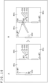
- FIGS. 9 to 11 is a specific example of the method for selecting the connection destination for the station.
- FIGS. 9 and 10 depict a typical wireless communication system that includes access points AP1 to AP3.
- the access points AP1 to AP3 are arranged in rooms 401a to 401c, respectively. It is assumed that the access points AP1 to AP3 are either all access points or all indirect access points. It is further assumed that the bandwidth of frequencies available for the access points AP1 to AP3, their number of sub-channels, and their transmission intensity of signals are all the same.
- the room 401a has a doorway 402a. There is a doorway 402b between the room 401a and the room 401b. There is a doorway 402c between the room 401a and the room 401c.
- the access point AP1 is closest to the station STA1, so that the intensity of reception from the access point AP1 is highest for the station STA1.
- the station STA1 selects the access point AP1 as the connection destination.
- the access point AP2 is closest to the station STA1, so that the intensity of reception from the access point AP2 is thus highest for the station STA1.
- the station STA1 changes the connection destination from the access point AP1 to the access point AP2. This shortens the transmission distance between the station STA1 and the access point that is the connection destination, which improves a communication rate and communication quality therebetween.
- the station STA1 selects the access point AP1 as the connection destination, as in the example in FIG. 9A.
- the intensity of reception from the access point AP2 is highest for the station STA1.
- the access point AP2 is under high load because it is already connected with stations STA2 to STA4. That means the Occupancy Ratio of the access point AP2 is higher than that of the access point AP1.
- the station STA1 does not change the connection destination and continues to be connected with the access point AP1. This prevents the station STA1 from connecting with the access point AP2 under high load, thereby preventing drops in communication rate and communication quality.
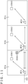
- FIG. 11 depicts a typical wireless communication system that includes access points AP11 to AP13.
- the access points AP11 to AP13 are arranged in rooms 411a to 411c, respectively.
- the access point AP11 is a direct access point connected directly to a wired backhaul 412.
- the number of hops for the access point AP11 is 0.
- the access point AP12 is an indirect access point connected to the wired backhaul 412 via the access point AP11.
- the number of hops for the access point AP12 is 1.
- the access point AP13 is an indirect access point connected to the wired backhaul 412 via the access points AP11 and AP12.
- the number of hops for the access point AP12 is 2.
- a station STA11 is connected to the access point AP11.
- a station STA12 is connected to the access point AP12 and connected to the access point AP11 via the access point AP12.
- a station STA13 is connected to the access point AP13, to the access point AP12 via the access point AP13, and to the access point AP11 via the access point AP12.
- the access point AP11 is connected directly or indirectly with the stations STA11 to STA13.
- the access point AP12 is connected directly or indirectly with the stations STA12 and STA13.
- the access point AP13 is connected directly with the station STA13.
- the Occupancy Ratio of the access point AP11 is thus higher than that of the access point AP12, in turn, the Occupancy Ratio of the access point AP12 is higher than the Occupancy Ratio of the access point AP13.
- a station STA14 exists on the boundary between the room 411a and the room 411b and is connectable to the access points AP11 and AP12.
- the access point AP12 is closer to the station STA14 than the access point AP11, so that the intensity of reception from the access point AP12 is higher than from the access point AP11 for the station STA14.
- the Occupancy Ratio of the access point AP12 is lower than that of the access point AP11.
- the access point AP12 appears to be more appropriate than the access point AP11 as the connection destination for the station STA14.
- the station STA14 selects the access point AP11 as the connection destination.
- the station STA11 Even if the station STA11 selects the access point AP12 as the connection destination, the station STA11 is eventually connected to the access point AP11 via the access point AP12. Thus, connecting the station STA11 directly to the access point AP11 without the intervention of the access point AP12 improves a communication rate and communication quality.
- the station STA14 selects the access point AP11 as the connection destination.
- the station can easily select the appropriate access point from among a plurality of access points on the basis of their Network Cost Info.
- the utilization efficiency of frequency resources is improved, for example, which leads to increased transmission amounts of signals, enhanced transmission rate of signals, and improvements in communication quality.
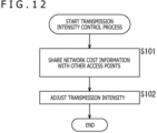
- each of the access points may control the transmission intensity of the Beacon frame or of the Probe Response frame on the basis of the Network Cost Info regarding the access points, thereby adjusting the range of connectable stations.
- step S101 the access point shares the Network Cost Info with other access points.
- control section 132 supplies the signal generation section 145 with the information to be stored in each field of an information sharing frame, and orders the signal generation section 145 to generate the information sharing frame.
- the signal generation section 145 generates the information sharing frame based on the information supplied from the control section 132.
- the signal generation section 145 sends the generated information sharing frame to the RF transmission section 147 via the analog signal conversion section 146.
- the information sharing frame includes at least the Network Cost Info depicted in FIG. 6 . Because the information sharing frame is broadcast to other access points, a broadcast address is set to the receiver address of the frame.
- the RF transmission section 147 transmits the information sharing frame via the antenna sharing section 141 and the antenna 121.
- the RF reception section 142 further receives information sharing frames sent from other access points via the antenna 121 and the antenna sharing section 141.
- the RF reception section 142 sends the received information sharing frames to the control section 132 via the digital signal conversion section 143 and the signal reception section 144.
- the control section 132 adjusts the intensity of transmission.
- the control section 132 controls the RF transmission section 147 to adjust the transmission intensity of frames (e.g., Beacon frame, Probe Response frame) to transmit the Network Cost Info to the station.
- the transmission intensity is adjusted in accordance with Conditions 1 to 3 below and based on the state of connection to the backhaul and on the status of use of frequency resources.
- the transmission intensity is made higher than the case where a wireless backhaul is connected.
- each access point adjusts the transmission intensity in a manner satisfying Conditions 1 to 3 above in coordination with surrounding access points.
- the transmission intensity of a direct access point is made higher than that of an indirect access point.
- the transmission intensity of the direct access point with a higher Occupancy Ratio is made higher than that of the direct access point with a lower Occupancy Ratio.
- the transmission intensity of the indirect access point with a smaller number of hops is made higher than that of the indirect access point with a larger number of hops.
- the transmission intensity of the indirect access point with a lower Occupancy Ratio is made higher than that of the indirect access point with a higher Occupancy Ratio.
- the lower limit of the transmission intensity may be determined in such a manner as to prevent each access point from getting disconnected from the currently connected station. This can bring about a case where none of Conditions 1 to 3 above is satisfied.
- each access point may, without coordinating with other access points, set its transmission intensity based on the state of connection to the backhaul and on the status of use of frequency resources. For instance, each access point may set its transmission intensity based on the type of the connected backhaul, on the number of hops, and on the Occupancy Ratio and in a manner satisfying Conditions 1 to 3 above using predetermined functions.
- the access point may request the station to change the connection destination. Specifically, after connection is established between the access point and the station in accordance with the protocol as described above with reference to FIG. 5 , the access point may transmit a Handover Request frame to the station. In response to this, the station disconnects with the access point, searches for another access point, and connects to the newly-found access point.
- the station performs the connection process after selecting the connection destination based on the Network Cost Info. This enables the station to connect with the appropriate access point more quickly.
- the wireless communication module 122 ( FIG. 1 ) and the wired communication module 123 ( FIG. 1 ) are each configured with a semiconductor chip.
- the communication module 111 ( FIG. 1 ), the communication module 211 ( FIG. 2 ), and the communication module 311 ( FIG. 3 ) may each be configured with a semiconductor chip as well.
- the access point transmits the Network Cost Info using the Beacon frame or the Probe Request frame.
- the Network Cost Info may be transmitted by use of some other suitable broadcast signal.
- the present technology may be applied to all communications based on methods by which a wireless terminal station selects the connection destination from among a plurality of wireless base stations to communicate with the selected connection destination.
- the series of processing described above may be executed either by hardware or by software.
- the programs constituting the software are installed into a suitable computer.
- Variations of the computer include one with the software installed beforehand in its dedicated hardware, and a general-purpose personal computer or like equipment capable of executing diverse functions based on the programs installed therein.
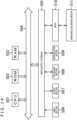
- FIG. 14 is a block diagram depicting a hardware configuration example of a computer that executes the above-described series of processing using programs.
- a CPU Central Processing Unit
- ROM Read Only Memory
- RAM Random Access Memory
- the bus 504 is further connected with an input/output interface 505.
- the input/output interface 505 is connected with an input section 506, an output section 507, a recording section 508, a communication section 509, and a drive 510.
- the input section 506 is typically configured with input switches, buttons, a microphone, and an imaging element.
- the output section 507 is typically configured with a display unit and speakers.
- the recording section 508 is typically configured with a hard disk and a nonvolatile memory.
- the communication section 509 is typically configured with a network interface.
- the drive 510 drives removable recording media 511 such as a magnetic disk, an optical disk, a magneto-optical disk, or a semiconductor memory.
- the CPU 501 may perform the above-mentioned series of processing typically by loading appropriate programs from the recording section 508 into the RAM 503 via the input/output interface 505 and the bus 504 and by executing the loaded programs.
- the programs to be executed by the computer 500 may be recorded, for example, on the removable recording media 511 as packaged media when offered.
- the programs may be offered alternatively via wired or wireless transmission media such as local area networks, the Internet, and digital satellite broadcasting.
- the programs may be installed into the recording section 508 from the removable recording media 511 attached to the drive 510 via the input/output interface 505.
- the programs may also be installed into the recording section 508 after being received by the communication section 509 via wired or wireless transmission media.
- the programs may alternatively be preinstalled in the ROM 502 or in the recording section 508.
- the programs for execution by the computer may be carried out chronologically in the depicted sequence in this specification, in parallel, or on an as-needed basis such as when they are invoked.
- system refers to an aggregate of a plurality of components (e.g., apparatuses or modules (parts)). It does not matter whether or not all components are housed in the same enclosure. Thus, a system may be configured with a plurality of apparatuses housed in separate enclosures and interconnected via a network, or with a single apparatus in a single enclosure that houses a plurality of modules.
- the present technology may be implemented as a cloud computing setup in which a single function is processed cooperatively by a plurality of networked apparatuses on a shared basis.
- each of the steps described in reference to the above-described flowcharts may be executed either by a single apparatus or by a plurality of apparatuses on a shared basis.
- a single step includes a plurality of processes
- these processes may be executed either by a single apparatus or by a plurality of apparatuses on a shared basis.
Landscapes
- Engineering & Computer Science (AREA)
- Computer Networks & Wireless Communication (AREA)
- Signal Processing (AREA)
- Computer Security & Cryptography (AREA)
- Mobile Radio Communication Systems (AREA)
Claims (13)
- Drahtlose Kommunikationsvorrichtung (201), umfassend:einen Kommunikationsabschnitt (131), der dazu konfiguriert ist, ein Rundfunksignal an eine drahtlose Endgerätestation (301) zu senden, das Netzwerkverbindungsinformationen bezüglich eines drahtlosen Kommunikationssystems mit einer Vielzahl von drahtlosen Basisstationen enthält, die miteinander kommunizieren, wobeidie drahtlose Kommunikationsvorrichtung dazu ausgelegt ist, als eine der Vielzahl von drahtlosen Basisstationen zu fungieren,wobei die Netzwerkverbindungsinformationen Backhaul-Verbindungsinformationen enthalten, die einen Verbindungsstatus mit einem Backhaul anzeigen,wobei die Backhaul-Verbindungsinformationen Informationen darüber enthalten, ob es sich bei dem Backhaul um ein drahtgebundenes oder ein drahtloses Backhaul handelt.
- Drahtlose Kommunikationsvorrichtung nach Anspruch 1, wobei die Backhaul-Verbindungsinformationen ferner die Anzahl der Hops enthalten, die die Anzahl der drahtlosen Basisstationen angibt, die durchlaufen werden müssen, bevor die drahtgebundene Backhaul-Verbindung hergestellt wird.
- Drahtlose Kommunikationsvorrichtung nach Anspruch 1, ferner umfassend:
einen Steuerabschnitt, der dazu konfiguriert ist, die Übertragungsintensität des Rundfunksignals basierend auf dem Verbindungsstatus mit dem Backhaul zu steuern. - Drahtlose Kommunikationsvorrichtung nach Anspruch 3, wobei der Steuerabschnitt dazu konfiguriert ist, die Übertragungsintensität des Rundfunksignals höher einzustellen, wenn ein drahtgebundenes Backhaul verbunden ist, als wenn ein drahtloses Backhaul verbunden ist.
- Drahtlose Kommunikationsvorrichtung nach Anspruch 4, wobei der Steuerabschnitt die Übertragungsintensität des Rundfunksignals umso höher einstellt, je kleiner die Anzahl der drahtlosen Basisstationen ist, die durchlaufen werden müssen, bevor die drahtgebundene Backhaul-Verbindung hergestellt wird.
- Drahtlose Kommunikationsvorrichtung nach Anspruch 3, wobei der Steuerabschnitt ferner dazu konfiguriert ist, die Übertragungsintensität des Rundfunksignals basierend auf dem Verbindungsstatus einer umgebenden drahtlosen Basisstation mit dem Backhaul zu steuern.
- Drahtlose Kommunikationsvorrichtung nach Anspruch 1, wobei die Netzwerkverbindungsinformationen Nutzungsinformationen enthalten, die einen Nutzungsstatus der verfügbaren Frequenzressourcen angeben.
- Drahtlose Kommunikationsvorrichtung nach Anspruch 7, wobei die Nutzungsinformationen den Nutzungsstatus der Frequenzressourcen für jeden der Unterkanäle angeben.
- Drahtlose Kommunikationsvorrichtung nach Anspruch 7, ferner umfassend:
einen Steuerabschnitt, der dazu konfiguriert ist, die Übertragungsintensität des Rundfunksignals basierend auf dem Nutzungsstatus der Frequenzressourcen zu steuern. - Drahtlose Kommunikationsvorrichtung nach Anspruch 9, wobei der Steuerabschnitt dazu konfiguriert ist, die Übertragungsintensität des Rundfunksignals so einzustellen, dass die Übertragungsintensität des Rundfunksignals umso höher eingestellt wird, je niedriger das Belegungsverhältnis der Frequenzressourcen ist.
- Drahtlose Kommunikationsvorrichtung nach Anspruch 9, wobei der Steuerabschnitt ferner die Übertragungsintensität des Rundfunksignals basierend auf einem Nutzungsstatus der Frequenzressourcen für eine umgebende drahtlose Basisstation steuert.
- Drahtloses Kommunikationsverfahren, das von einer drahtlosen Kommunikationsvorrichtung (201) durchgeführt wird, das Verfahren umfassend:Übertragen (S1, S4) eines Rundfunksignals, das Netzwerkverbindungsinformationen bezüglich eines drahtlosen Kommunikationssystems mit einer Vielzahl von drahtlosen Basisstationen enthält, die miteinander kommunizieren, an eine drahtlose Endgerätestation; undFungieren als eine der Vielzahl von drahtlosen Basisstationen;wobei die Netzwerkverbindungsinformationen Backhaul-Verbindungsinformationen enthalten, die einen Verbindungsstatus mit einem Backhaul anzeigen;wobei die Backhaul-Verbindungsinformationen Informationen darüber enthalten, ob es sich bei dem Backhaul um ein drahtgebundenes oder ein drahtloses Backhaul handelt.
- Drahtlose Kommunikationsvorrichtung (301), umfassend:einen Kommunikationsabschnitt (131), der dazu konfiguriert ist, ein Rundfunksignal mit Netzwerkverbindungsinformationen bezüglich eines drahtlosen Kommunikationssystems von jeder einer Vielzahl von drahtlosen Basisstationen (201) zu empfangen, die das drahtlose Kommunikationssystem bilden und miteinander kommunizieren, wobeidie drahtlose Kommunikationsvorrichtung dazu ausgelegt ist, als drahtlose Endgerätestation zu fungieren,ein Steuerabschnitt (331) dazu konfiguriert ist, basierend auf den Netzwerkverbindungsinformationen ein Verbindungsziel aus der Vielzahl von drahtlosen Basisstationen auszuwählen,die Netzwerkverbindungsinformationen Backhaul-Verbindungsinformationen enthalten, die einen Verbindungsstatus der drahtlosen Basisstationen mit einem Backhaul anzeigen,wobei die Backhaul-Verbindungsinformationen Informationen darüber enthalten, ob es sich bei dem Backhaul um ein drahtgebundenes oder ein drahtloses Backhaul handelt.
Applications Claiming Priority (2)
| Application Number | Priority Date | Filing Date | Title |
|---|---|---|---|
| JP2018073927 | 2018-04-06 | ||
| PCT/JP2019/011985 WO2019193990A1 (ja) | 2018-04-06 | 2019-03-22 | 無線通信装置及び無線通信方法 |
Publications (3)
| Publication Number | Publication Date |
|---|---|
| EP3780747A1 EP3780747A1 (de) | 2021-02-17 |
| EP3780747A4 EP3780747A4 (de) | 2021-06-02 |
| EP3780747B1 true EP3780747B1 (de) | 2025-05-28 |
Family
ID=68100592
Family Applications (1)
| Application Number | Title | Priority Date | Filing Date |
|---|---|---|---|
| EP19781967.5A Active EP3780747B1 (de) | 2018-04-06 | 2019-03-22 | Auswahl des access point auf basis des backhaul-status |
Country Status (3)
| Country | Link |
|---|---|
| US (3) | US11425629B2 (de) |
| EP (1) | EP3780747B1 (de) |
| WO (1) | WO2019193990A1 (de) |
Families Citing this family (2)
| Publication number | Priority date | Publication date | Assignee | Title |
|---|---|---|---|---|
| US11363657B1 (en) * | 2019-05-16 | 2022-06-14 | Marvell Asia Pte Ltd | WiFi network operation with channel aggregation |
| FR3130493B1 (fr) * | 2021-12-15 | 2024-07-26 | Sagemcom Broadband Sas | Procede et dispositif de selection d’un nœud dans un reseau local |
Family Cites Families (11)
| Publication number | Priority date | Publication date | Assignee | Title |
|---|---|---|---|---|
| US7797018B2 (en) | 2005-04-01 | 2010-09-14 | Interdigital Technology Corporation | Method and apparatus for selecting a multi-band access point to associate with a multi-band mobile station |
| US8457674B2 (en) | 2006-09-29 | 2013-06-04 | Intel Corporation | Architecture, protocols and frame formats for wireless multi-hop relay networks |
| US8185060B2 (en) | 2008-04-22 | 2012-05-22 | Qualcomm Incorporated | Serving base station selection using backhaul quality information |
| US20130142136A1 (en) * | 2011-10-21 | 2013-06-06 | Samsung Electronics Co., Ltd. | Methods and apparatus for adaptive wireless backhaul and networks |
| EP2901632B1 (de) | 2012-09-29 | 2018-05-30 | Assia Spe, Llc | Optimiertes steuerungssystem zur zusammenfassung mehrerer breitbandverbindungen über funkschnittstellen |
| US9655037B2 (en) | 2014-04-07 | 2017-05-16 | Qualcomm Incorporated | Method and apparatus for an improved mechanism for selecting an access point |
| JP6154857B2 (ja) | 2015-06-30 | 2017-06-28 | ソフトバンク株式会社 | 無線通信中継装置及び無線通信中継方法 |
| WO2017122977A1 (en) | 2016-01-14 | 2017-07-20 | Samsung Electronics Co., Ltd. | Apparatus and method for supporting unified wireless backhaul and access network in wireless communication system |
| US10440688B2 (en) | 2016-01-14 | 2019-10-08 | Samsung Electronics Co., Ltd. | Frame structures and signaling techniques for a unified wireless backhaul and access network |
| JP6974226B2 (ja) | 2018-03-23 | 2021-12-01 | ヒロセ電機株式会社 | 対の圧着片を有するハウジングを備えた同軸ケーブルコネクタ |
| US10805862B2 (en) * | 2018-08-03 | 2020-10-13 | T-Mobile Usa, Inc. | Sensor and self-learning based dynamic frequency assignment for wireless networks |
-
2019
- 2019-03-22 EP EP19781967.5A patent/EP3780747B1/de active Active
- 2019-03-22 US US17/042,375 patent/US11425629B2/en active Active
- 2019-03-22 WO PCT/JP2019/011985 patent/WO2019193990A1/ja not_active Ceased
-
2022
- 2022-07-22 US US17/871,284 patent/US11729705B2/en active Active
-
2023
- 2023-07-03 US US18/346,452 patent/US12185224B2/en active Active
Also Published As
| Publication number | Publication date |
|---|---|
| WO2019193990A1 (ja) | 2019-10-10 |
| US20210037451A1 (en) | 2021-02-04 |
| US11425629B2 (en) | 2022-08-23 |
| US11729705B2 (en) | 2023-08-15 |
| US12185224B2 (en) | 2024-12-31 |
| US20230354162A1 (en) | 2023-11-02 |
| EP3780747A1 (de) | 2021-02-17 |
| EP3780747A4 (de) | 2021-06-02 |
| US20220361090A1 (en) | 2022-11-10 |
Similar Documents
| Publication | Publication Date | Title |
|---|---|---|
| US8170503B2 (en) | Apparatus and method for transmitting data and apparatus and method for receiving data | |
| KR20220037306A (ko) | 무선 통신 시스템에서 프론트홀 전송을 위한 장치 및 방법 | |
| US10367563B2 (en) | Base station device, wireless terminal device, and wireless communication method | |
| KR20220037308A (ko) | 무선 통신 시스템에서 프론트홀 전송을 위한 장치 및 방법 | |
| US8437319B2 (en) | Wireless network system and method of configuring the same | |
| JP7816460B2 (ja) | 無線通信制御装置および無線通信制御方法 | |
| JP2024175131A (ja) | 通信装置、通信方法、およびプログラム | |
| US12185224B2 (en) | Wireless communication apparatus and wireless communication method | |
| US9942883B2 (en) | Method and apparatus for allocating bandwidth of wireless network where both wide-band and narrow-band signals are transmitted, and method and apparatus for transmitting and receiving data on the network | |
| JP7293435B2 (ja) | Pcp/ap通信装置および通信方法 | |
| JP2009212968A (ja) | 無線通信装置、無線通信装置の制御方法、および無線通信装置の制御プログラム | |
| US20080112369A1 (en) | Method and apparatus for allocating bandwidth of wireless network, and method and apparatus for transmitting and receiving data on the network | |
| US20230337226A1 (en) | Wireless communication device and method | |
| CN118614103A (zh) | 通信装置及通信方法 | |
| EP3787346A1 (de) | Drahtloskommunikationsvorrichtung und drahtloskommunikationsverfahren | |
| KR20110119520A (ko) | 무선랜 시스템에서 간섭 회피 방법 및 장치 | |
| KR100801000B1 (ko) | 무선 데이터를 송수신하는 방법 및 장치 | |
| US20080107205A1 (en) | Apparatus for transmitting and receiving wireless data and method of transmitting and receiving wireless data | |
| KR20080090957A (ko) | 무선 네트워크 시스템 및 상기 무선 네트워크 시스템을구성하는 방법 | |
| US12237886B2 (en) | Multi-antenna wireless transmitter and method with MIMO beamforming | |
| KR101424527B1 (ko) | 데이터를 송수신하는 장치 및 방법 | |
| WO2023095544A1 (ja) | 通信装置、通信方法、およびプログラム | |
| CN117395721A (zh) | 链路负载均衡方法、多链路接入设备、终端及存储介质 |
Legal Events
| Date | Code | Title | Description |
|---|---|---|---|
| STAA | Information on the status of an ep patent application or granted ep patent |
Free format text: STATUS: THE INTERNATIONAL PUBLICATION HAS BEEN MADE |
|
| PUAI | Public reference made under article 153(3) epc to a published international application that has entered the european phase |
Free format text: ORIGINAL CODE: 0009012 |
|
| STAA | Information on the status of an ep patent application or granted ep patent |
Free format text: STATUS: REQUEST FOR EXAMINATION WAS MADE |
|
| 17P | Request for examination filed |
Effective date: 20200924 |
|
| AK | Designated contracting states |
Kind code of ref document: A1 Designated state(s): AL AT BE BG CH CY CZ DE DK EE ES FI FR GB GR HR HU IE IS IT LI LT LU LV MC MK MT NL NO PL PT RO RS SE SI SK SM TR |
|
| AX | Request for extension of the european patent |
Extension state: BA ME |
|
| A4 | Supplementary search report drawn up and despatched |
Effective date: 20210503 |
|
| RIC1 | Information provided on ipc code assigned before grant |
Ipc: H04W 48/10 20090101AFI20210426BHEP Ipc: H04W 48/16 20090101ALN20210426BHEP Ipc: H04W 48/18 20090101ALN20210426BHEP Ipc: H04W 52/46 20090101ALN20210426BHEP Ipc: H04W 92/20 20090101ALN20210426BHEP Ipc: H04W 84/12 20090101ALN20210426BHEP |
|
| DAV | Request for validation of the european patent (deleted) | ||
| DAX | Request for extension of the european patent (deleted) | ||
| RAP3 | Party data changed (applicant data changed or rights of an application transferred) |
Owner name: SONY GROUP CORPORATION |
|
| STAA | Information on the status of an ep patent application or granted ep patent |
Free format text: STATUS: EXAMINATION IS IN PROGRESS |
|
| 17Q | First examination report despatched |
Effective date: 20230103 |
|
| GRAP | Despatch of communication of intention to grant a patent |
Free format text: ORIGINAL CODE: EPIDOSNIGR1 |
|
| STAA | Information on the status of an ep patent application or granted ep patent |
Free format text: STATUS: GRANT OF PATENT IS INTENDED |
|
| RIC1 | Information provided on ipc code assigned before grant |
Ipc: H04W 84/12 20090101ALN20241205BHEP Ipc: H04W 92/20 20090101ALN20241205BHEP Ipc: H04W 52/46 20090101ALN20241205BHEP Ipc: H04W 48/18 20090101ALN20241205BHEP Ipc: H04W 48/16 20090101ALN20241205BHEP Ipc: H04W 48/10 20090101AFI20241205BHEP |
|
| RIC1 | Information provided on ipc code assigned before grant |
Ipc: H04W 84/12 20090101ALN20241219BHEP Ipc: H04W 92/20 20090101ALN20241219BHEP Ipc: H04W 52/46 20090101ALN20241219BHEP Ipc: H04W 48/18 20090101ALN20241219BHEP Ipc: H04W 48/16 20090101ALN20241219BHEP Ipc: H04W 48/10 20090101AFI20241219BHEP |
|
| INTG | Intention to grant announced |
Effective date: 20250103 |
|
| GRAS | Grant fee paid |
Free format text: ORIGINAL CODE: EPIDOSNIGR3 |
|
| GRAA | (expected) grant |
Free format text: ORIGINAL CODE: 0009210 |
|
| STAA | Information on the status of an ep patent application or granted ep patent |
Free format text: STATUS: THE PATENT HAS BEEN GRANTED |
|
| P01 | Opt-out of the competence of the unified patent court (upc) registered |
Free format text: CASE NUMBER: APP_16799/2025 Effective date: 20250407 |
|
| AK | Designated contracting states |
Kind code of ref document: B1 Designated state(s): AL AT BE BG CH CY CZ DE DK EE ES FI FR GB GR HR HU IE IS IT LI LT LU LV MC MK MT NL NO PL PT RO RS SE SI SK SM TR |
|
| REG | Reference to a national code |
Ref country code: GB Ref legal event code: FG4D |
|
| REG | Reference to a national code |
Ref country code: CH Ref legal event code: EP |
|
| REG | Reference to a national code |
Ref country code: IE Ref legal event code: FG4D Ref country code: DE Ref legal event code: R096 Ref document number: 602019070552 Country of ref document: DE |
|
| REG | Reference to a national code |
Ref country code: NL Ref legal event code: FP |
|
| PG25 | Lapsed in a contracting state [announced via postgrant information from national office to epo] |
Ref country code: FI Free format text: LAPSE BECAUSE OF FAILURE TO SUBMIT A TRANSLATION OF THE DESCRIPTION OR TO PAY THE FEE WITHIN THE PRESCRIBED TIME-LIMIT Effective date: 20250528 Ref country code: ES Free format text: LAPSE BECAUSE OF FAILURE TO SUBMIT A TRANSLATION OF THE DESCRIPTION OR TO PAY THE FEE WITHIN THE PRESCRIBED TIME-LIMIT Effective date: 20250528 |
|
| REG | Reference to a national code |
Ref country code: LT Ref legal event code: MG9D |
|
| PG25 | Lapsed in a contracting state [announced via postgrant information from national office to epo] |
Ref country code: GR Free format text: LAPSE BECAUSE OF FAILURE TO SUBMIT A TRANSLATION OF THE DESCRIPTION OR TO PAY THE FEE WITHIN THE PRESCRIBED TIME-LIMIT Effective date: 20250829 Ref country code: NO Free format text: LAPSE BECAUSE OF FAILURE TO SUBMIT A TRANSLATION OF THE DESCRIPTION OR TO PAY THE FEE WITHIN THE PRESCRIBED TIME-LIMIT Effective date: 20250828 |
|
| PG25 | Lapsed in a contracting state [announced via postgrant information from national office to epo] |
Ref country code: PL Free format text: LAPSE BECAUSE OF FAILURE TO SUBMIT A TRANSLATION OF THE DESCRIPTION OR TO PAY THE FEE WITHIN THE PRESCRIBED TIME-LIMIT Effective date: 20250528 |
|
| PG25 | Lapsed in a contracting state [announced via postgrant information from national office to epo] |
Ref country code: BG Free format text: LAPSE BECAUSE OF FAILURE TO SUBMIT A TRANSLATION OF THE DESCRIPTION OR TO PAY THE FEE WITHIN THE PRESCRIBED TIME-LIMIT Effective date: 20250528 |
|
| PG25 | Lapsed in a contracting state [announced via postgrant information from national office to epo] |
Ref country code: HR Free format text: LAPSE BECAUSE OF FAILURE TO SUBMIT A TRANSLATION OF THE DESCRIPTION OR TO PAY THE FEE WITHIN THE PRESCRIBED TIME-LIMIT Effective date: 20250528 |
|
| PG25 | Lapsed in a contracting state [announced via postgrant information from national office to epo] |
Ref country code: RS Free format text: LAPSE BECAUSE OF FAILURE TO SUBMIT A TRANSLATION OF THE DESCRIPTION OR TO PAY THE FEE WITHIN THE PRESCRIBED TIME-LIMIT Effective date: 20250828 |
|
| PG25 | Lapsed in a contracting state [announced via postgrant information from national office to epo] |
Ref country code: IS Free format text: LAPSE BECAUSE OF FAILURE TO SUBMIT A TRANSLATION OF THE DESCRIPTION OR TO PAY THE FEE WITHIN THE PRESCRIBED TIME-LIMIT Effective date: 20250928 |
|
| PG25 | Lapsed in a contracting state [announced via postgrant information from national office to epo] |
Ref country code: LV Free format text: LAPSE BECAUSE OF FAILURE TO SUBMIT A TRANSLATION OF THE DESCRIPTION OR TO PAY THE FEE WITHIN THE PRESCRIBED TIME-LIMIT Effective date: 20250528 |
|
| REG | Reference to a national code |
Ref country code: AT Ref legal event code: MK05 Ref document number: 1799369 Country of ref document: AT Kind code of ref document: T Effective date: 20250528 |
|
| PG25 | Lapsed in a contracting state [announced via postgrant information from national office to epo] |
Ref country code: AT Free format text: LAPSE BECAUSE OF FAILURE TO SUBMIT A TRANSLATION OF THE DESCRIPTION OR TO PAY THE FEE WITHIN THE PRESCRIBED TIME-LIMIT Effective date: 20250528 Ref country code: SM Free format text: LAPSE BECAUSE OF FAILURE TO SUBMIT A TRANSLATION OF THE DESCRIPTION OR TO PAY THE FEE WITHIN THE PRESCRIBED TIME-LIMIT Effective date: 20250528 Ref country code: DK Free format text: LAPSE BECAUSE OF FAILURE TO SUBMIT A TRANSLATION OF THE DESCRIPTION OR TO PAY THE FEE WITHIN THE PRESCRIBED TIME-LIMIT Effective date: 20250528 |
|
| PG25 | Lapsed in a contracting state [announced via postgrant information from national office to epo] |
Ref country code: CZ Free format text: LAPSE BECAUSE OF FAILURE TO SUBMIT A TRANSLATION OF THE DESCRIPTION OR TO PAY THE FEE WITHIN THE PRESCRIBED TIME-LIMIT Effective date: 20250528 |
|
| PG25 | Lapsed in a contracting state [announced via postgrant information from national office to epo] |
Ref country code: EE Free format text: LAPSE BECAUSE OF FAILURE TO SUBMIT A TRANSLATION OF THE DESCRIPTION OR TO PAY THE FEE WITHIN THE PRESCRIBED TIME-LIMIT Effective date: 20250528 |
|
| PG25 | Lapsed in a contracting state [announced via postgrant information from national office to epo] |
Ref country code: SK Free format text: LAPSE BECAUSE OF FAILURE TO SUBMIT A TRANSLATION OF THE DESCRIPTION OR TO PAY THE FEE WITHIN THE PRESCRIBED TIME-LIMIT Effective date: 20250528 Ref country code: RO Free format text: LAPSE BECAUSE OF FAILURE TO SUBMIT A TRANSLATION OF THE DESCRIPTION OR TO PAY THE FEE WITHIN THE PRESCRIBED TIME-LIMIT Effective date: 20250528 |
|
| REG | Reference to a national code |
Ref country code: DE Ref legal event code: R097 Ref document number: 602019070552 Country of ref document: DE |
|
| PGFP | Annual fee paid to national office [announced via postgrant information from national office to epo] |
Ref country code: NL Payment date: 20260219 Year of fee payment: 8 |
|
| PLBE | No opposition filed within time limit |
Free format text: ORIGINAL CODE: 0009261 |
|
| STAA | Information on the status of an ep patent application or granted ep patent |
Free format text: STATUS: NO OPPOSITION FILED WITHIN TIME LIMIT |
|
| PGFP | Annual fee paid to national office [announced via postgrant information from national office to epo] |
Ref country code: GB Payment date: 20260219 Year of fee payment: 8 |
|
| REG | Reference to a national code |
Ref country code: CH Ref legal event code: L10 Free format text: ST27 STATUS EVENT CODE: U-0-0-L10-L00 (AS PROVIDED BY THE NATIONAL OFFICE) Effective date: 20260409 |
|
| PGFP | Annual fee paid to national office [announced via postgrant information from national office to epo] |
Ref country code: DE Payment date: 20260219 Year of fee payment: 8 |
|
| PGFP | Annual fee paid to national office [announced via postgrant information from national office to epo] |
Ref country code: IT Payment date: 20260219 Year of fee payment: 8 |