EP3780926B1 - Vorrichtung zur verwaltung einer substratverarbeitungsmaschine - Google Patents
Vorrichtung zur verwaltung einer substratverarbeitungsmaschine Download PDFInfo
- Publication number
- EP3780926B1 EP3780926B1 EP18911641.1A EP18911641A EP3780926B1 EP 3780926 B1 EP3780926 B1 EP 3780926B1 EP 18911641 A EP18911641 A EP 18911641A EP 3780926 B1 EP3780926 B1 EP 3780926B1
- Authority
- EP
- European Patent Office
- Prior art keywords
- software
- version
- work machine
- production process
- board work
- Prior art date
- Legal status (The legal status is an assumption and is not a legal conclusion. Google has not performed a legal analysis and makes no representation as to the accuracy of the status listed.)
- Active
Links
Images


Classifications
-
- G—PHYSICS
- G06—COMPUTING OR CALCULATING; COUNTING
- G06F—ELECTRIC DIGITAL DATA PROCESSING
- G06F8/00—Arrangements for software engineering
- G06F8/60—Software deployment
- G06F8/65—Updates
-
- H—ELECTRICITY
- H05—ELECTRIC TECHNIQUES NOT OTHERWISE PROVIDED FOR
- H05K—PRINTED CIRCUITS; CASINGS OR CONSTRUCTIONAL DETAILS OF ELECTRIC APPARATUS; MANUFACTURE OF ASSEMBLAGES OF ELECTRICAL COMPONENTS
- H05K13/00—Apparatus or processes specially adapted for manufacturing or adjusting assemblages of electric components
- H05K13/08—Monitoring manufacture of assemblages
- H05K13/0882—Control systems for mounting machines or assembly lines, e.g. centralized control, remote links, programming of apparatus and processes as such
-
- H—ELECTRICITY
- H05—ELECTRIC TECHNIQUES NOT OTHERWISE PROVIDED FOR
- H05K—PRINTED CIRCUITS; CASINGS OR CONSTRUCTIONAL DETAILS OF ELECTRIC APPARATUS; MANUFACTURE OF ASSEMBLAGES OF ELECTRICAL COMPONENTS
- H05K13/00—Apparatus or processes specially adapted for manufacturing or adjusting assemblages of electric components
- H05K13/04—Mounting of components, e.g. of leadless components
- H05K13/0404—Pick-and-place heads or apparatus, e.g. with jaws
-
- Y—GENERAL TAGGING OF NEW TECHNOLOGICAL DEVELOPMENTS; GENERAL TAGGING OF CROSS-SECTIONAL TECHNOLOGIES SPANNING OVER SEVERAL SECTIONS OF THE IPC; TECHNICAL SUBJECTS COVERED BY FORMER USPC CROSS-REFERENCE ART COLLECTIONS [XRACs] AND DIGESTS
- Y02—TECHNOLOGIES OR APPLICATIONS FOR MITIGATION OR ADAPTATION AGAINST CLIMATE CHANGE
- Y02P—CLIMATE CHANGE MITIGATION TECHNOLOGIES IN THE PRODUCTION OR PROCESSING OF GOODS
- Y02P90/00—Enabling technologies with a potential contribution to greenhouse gas [GHG] emissions mitigation
- Y02P90/02—Total factory control, e.g. smart factories, flexible manufacturing systems [FMS] or integrated manufacturing systems [IMS]
Definitions
- the present invention relates to a management device for a board work machine.
- a board work machine for use in production of board products includes a component mounter for mounting supplied components on boards.
- the component mounter is made up of multiple constitutive devices such as a component supply device, a component transfer device, and the like.
- the constitutive devices executes firmware corresponding to required functions to control various operations including a component supply and the like.
- firmware may need a version upgrading as a result of addition of a new function.
- Patent Literature 1 discloses a configuration in which a component mounter automatically executes an update processing of firmware based on a version of firmware installed into a constitutive device.
- WO 2015121942 relates to managing of software versions in constituent devices of substrate production apparatus including machines like a solder printing machine, a component mounting machine, a reflow machine and the like.
- a management device is used to manage the firmware in all constituent devices also based on a function that is required by a production process.
- JP 2008205075 relates to updating the software of board work machines. Specifically, this document shows updating a machine while it is running at a favorable point of time. Furthermore, it is mentioned that updating may be done by writing the update to a different position in the storage than the position of the present software.
- Patent Literature 1 JP-A- 2010-182768
- the component mounter cannot execute the mounting process of mounting a component. Therefore, there may be a possibility that the production efficiency of the component mounter is reduced due to the execution of the update processing of software, that is, firmware that the constitutive device executes.
- versions of software are desired to be managed more appropriately.
- An object of the present description is to provide a management device for a board work machine which can achieve an improvement in production efficiency of the board work machine while managing appropriately software that is used by constitutive device for its control.
- the present description discloses a management device for a board work machine including a storage device storing version information in which a current version of software executed by a constitutive device of a board work machine in a production process is associated individually with the multiple constitutive devices, and a version designation section configured to designate a version of the software which is to be applied to the production process based on a type of the production process and the version information.
- the version of the software executed by the board work machine at the current point in time is managed.
- the management device which is an external device of the board work machine, to manage the version of the software, whereby the manageability of the board work machine is improved.
- the management device designates the version of the software that is applied for the production process based on the version information. This enables the board work machine to control the various types of operations using the designated version of software suitable for the production process. As a result, production efficiency can be improved.
- the management device manages a version of software that a constitutive device of the board work machine executes.
- a mode will be described in which the management device manages control device 50, which constitutes a managing target, of component mounter 2, which constitutes a board work machine.
- Component mounter 2 makes up a production line for use in producing board products.
- production line L1 is made up of multiple board work machines which are set in a conveyance direction of board 90 (refer to Fig. 2 ). Each of the multiple board work machines is connected with host computer 60, which collectively controls production line L1, so as to communicate therewith.
- Production line L1 which is one of production lines, includes printer 1, multiple component mounters 2, reflow furnace 3, and inspector 4, which make up the multiple board work machines.
- Printer 1 prints a paste-state solder in a mounting position of a component on board 90 which is conveyed in or loaded.
- Each of multiple component mounters 2 mount components on board 90 which is conveyed from an upstream side of production line L1. The configuration of component mounter 2 will be described later on.
- Reflow furnace 3 heats board 90 conveyed from the upstream side of production line L1 so as to melt the solder on board 90 and executes a required soldering.
- Inspector 4 inspects whether a board product produced by production line L1 functions properly.
- three production lines L1-L3 are installed in a board products assembling plant.
- Second and third production lines L2, L3 have a substantially similar configuration to that of first production line L1 described above, a detailed description of second and third production lines L2, L3 will be omitted herein.
- Host computer 60 also controls second production line L2 and third production line L3 collectively, in addition to first production line L1.
- the configurations of three production lines L1 to L3 can be equipped with additional configurations or can be modified in accordance with, for example, types of boards to be produced.
- a board work machine such as a buffer device for temporarily holding board 90 conveyed, a board supply device, a board flipping device, various types of inspectors, a shield mounting device, an adhesive application device, an ultraviolet ray irradiation device, or the like can be set in three production lines L1 to L3 as required.
- Component mounter 2 executes a mounting process of mounting a component on board 90.
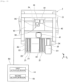
- component mounter 2 includes board conveyance device 10, component supply device 20, component transfer device 30, part camera 41, board camera 42, and control device 50.
- Board conveyance device 10 is made up of a belt conveyor and a positioning device. Board conveyance device 10 sequentially conveys board 90 in a conveyance direction and positions board 90 in a predetermined position within component mounter 2. Board conveyance device 10 conveys out board 90 to an outside of component mounter 2 after the mounting process is ended.
- Component supply device 20 supplies a component that is to be mounted on board 90.
- Component supply device 20 includes feeders 22 that are set in multiple slots 21. Feeder 22 feeds and moves a carrier tape in which a number of components are accommodated to supply components so as to be picked up. Additionally, component supply device 20 supplies, for example, relatively large components in such a state as to be arranged neatly on tray 25 placed in pallet 24.
- Storage device 23 of component supply device 20 accommodates multiple pallets 24 and pulls out a predetermined pallet 24 in accordance with a mounting process so as to supply components thereon.
- Component transfer device 30 transfers the component supplied by component supply device 20 to a predetermined mounting position on board 90 which is conveyed into an interior of component mounter 2 by board conveyance device 10.
- Head driving device 31 of component transfer device 30 moves moving table 32 in a horizontal direction (an X-axis direction and a Y-axis direction) using a linear motion mechanism.
- Mounting head 33 is fixed to moving table 32 with a clamping member, now shown, in such a manner as to be exchanged.
- Mounting head 33 supports multiple suction nozzles 34 rotatably and in such a manner as to be raised and lowered. Suction nozzle 34 picks up a component supplied by feeder 22 using a negative pressure air.
- Part camera 41 and board camera 42 are a digital imaging device having an imaging element such as a CMOS. Part camera 41 and board camera 42 execute imaging based on a control signal and transmit image data acquired through the imaging. Part camera 41 is configured to image a component held by suction nozzle 34 of mounting head 33 from below. Board camera 42 is configured to image board 90 from above.
- Control device 50 is made up mainly of CPU, various types of memories, and a control circuit. Control device 50 controls a mounting process of mounting a component on board 90.
- the mounting process is a type of a production process and includes a process of repeating multiple times a pick-and-place cycle (hereinafter, also, referred to as a "PP cycle") in which a component supplied by component supply device 20 is picked up and is then mounted in the predetermined position on board 90.
- PP cycle pick-and-place cycle
- control device 50 controls the operation of component transfer device 30 based on information outputted from various sensors, the results of image processing, or a control program stored in advance. As a result, positions and angles of multiple suction nozzles 34 supported on mounting head 33 are controlled.
- board conveyance device 10 In component mounter 2 configured as described above, board conveyance device 10, feeders 22, accommodation device 23, head driving device 31, mounting head 33, part camera 41, board camera 42, and control device 50 are constitutive devices which make up component mounter 2. These constitutive devices execute software corresponding to required functions (for example, a function of feeder 22 of supplying a component, and a function of control device 50 of controlling the operation of component transfer device 30). In the present embodiment, the software is firmware installed into the constitutive devices.
- control device 50 is configured to install in advance multiple versions of software which differ from each other. More specifically speaking, there are secured in control device 50 first activation region 51 and second activation region 52 which can execute selectively the same types of software installed therein. For example, versions (Ver 2.1, Ver 4.0), which differ from each other, are installed in first activation region 51 and second activation region, as shown in Table 2 in Fig. 3 , of control device 50 of each of multiple component mounters 2 making up first production line L1.
- Control device 50 is notified of a designated version of software that control device 50 is to execute by management device 70, which will be described later on, and activates software corresponding to the designated version.
- management device 70 manages versions of software that are individually installed in multiple production lines L1 to L3. That is, the multiple versions of software installed in individual control devices 50 of multiple component mounters 2 which make up first production line L1 are common. However, the versions of software may be managed in each of multiple control devices 50 in same production line L1.
- Host computer 60 monitors operating statuses of production lines L1 to L3 and controls board work machines such as component mounters 2.
- Host computer 60 functions as management device 70 for the board work machines with constitutive device and installed software.
- management device 70 manages control device 50, as a managing target, which is one of the constitutive devices of component mounter 2 and manages specifically versions of software programmed into control device 50.
- management device 70 includes storage device 71, version designation section 72, and updating section 73.
- Storage device 71 is made up of an optical drive device such as a hard disk device or a flash memory. This storage device 71 stores various types of data such as control programs for use in controlling the board work machines.
- Storage device 71 stores in advance production plan M1, version information M3, function information M4, and version application plan M5.
- production plan M1 described above indicates target production numbers (T1, T2, T3, ...) for production types (U1, U2, U3, ...) of board products in multiple production lines L1 to L3.
- Version information M2 is information in which the current version of software executed by the constitutive device of the board work machine in a production process (a mounting process) is associated with the multiple constitutive devices. More specifically speaking, in the present embodiment, version information M2 indicates the current version of software executed by control device 50 of component mounter 2 in the mounting process (for example, firmware for controlling the operation of component transfer device 30) in association with control devices 50 of each of multiple production lines L1 to L3.
- control device 50 can install versions of software which differ from each other.
- version information M2 stores, of two types of versions installed, a version that is executed last as the current version (thick frame sections in Table 2 in Fig. 3 ).
- the current version executed last by multiple control devices 50 in first production line L1 Ver 4.0 that is installed in second activation region 52.
- function information M3 is information in which functions of software are associated with multiple versions. Specifically speaking, in function information M3, items such as a basic operation (for example, the operation of component transfer device 30 in the mounting process), which is a main function, whether a version is applicable to an optional device, a dedicated operation corresponding to a special mounting process, whether there exists a drawback recognized, and the like are linked with each version.
- a basic operation for example, the operation of component transfer device 30 in the mounting process
- Ver2. 1 is not applicable to optional device but copes with a dedicated operation.
- Ver4. 0 is recorded as not applicable to optional device and a dedicated operation but executing a good basic operation by improving software or the like.
- Application information M4 is information in which functions of software required in production processes (mounting processes) are associated individually with types of production processes. Specifically speaking, in application information M4, as shown in Table 4 in Fig. 3 , types (P1, P2, P3, ...) of mounting processes which are executed to produce product types (U1, U2, U3, 7) are associated individually with functions of software required in the mounting processes. For example, according to Table 4 of Fig. 3 , a mounting process (P4) which is executed to produce a product type (U4) is required to have a function applicable to optional device.
- Version application plan M5 indicates versions which are to be applied individually to mounting processes scheduled to be executed. Version application plan M5 is generated by version designation section 72, which will be described later on in a management process of software. The management process of software and version application plan M5 will be described in detail later on.
- Version designation section 72 designates a version of software applied to a production process (a mounting process) based on a type of the production process and version information M2.
- version designation section 72 designates a version of software which is applied to a mounting process based on production plan M1, function information M3, and application information M4, which record types of mounting processes scheduled to be executed.
- software whose versions are different from each other, is installed in advance individually in first activation region 51 and second activation region 52 of control device 50.
- version designation section 72 designates a version of software applied to a mounting process to be executed by selecting one of the multiple versions of software installed in control device 50 based on a type of the mounting process.
- management device 70 can allow the version of software suitable for the mounting process to be executed without involving a new install operation.
- updating section 73 updates any one of the multiple versions of software.
- control device 50 is executing one or a first version of software of the multiple versions of software based on production plan M1
- updating section 73 updates a second version of software. For example, when a version of software suitable for a mounting process scheduled to be executed is not installed in control device 50, updating section 73 updates software at rest before the mounting process in question is executed. This allows a designated version of software to be installed before the scheduled mounting process is executed.
- updating section 73 can set a version of software suitable for a mounting process by recognizing a mounting process scheduled to be executed based on production plan M1. Further, the updating section can set a timing when the software is updated based on production plan M1. As a result, a reduction in production efficiency associated with the installation of software can be prevented.
- the mounting process executed by component mounter 2 includes the process of repeating the PP cycle as described above.
- updating section 73 updates the software during a low load period in a mounting process when a processing load of control device 50 is reduced more than while control device 50 is executing the PP cycle.
- a software updating process takes a predetermined period of time, and a predetermined load is exerted on a control device of target control device 50.
- an updating process of software is executed, there may be a possibility that the operation of control device 50 is badly affected depending upon an updating execution timing in the mounting process. Then, the operation of control device 50 can be prevented from being affected badly in the mounting process by executing the updating process during the low load period as described above.
- a software management processing executed by management device 70 will be described by reference to Figs. 3 to 5 .
- a managing target of management device 70 is control device 50 making up component mounter 2, which constitutes a board work machine.
- Control device 50 has installed therein software for controlling the operation of component transfer device 30 in a mounting process. More specifically speaking, as shown in Table 2-1 in Fig. 4 , software of Ver2.0 is installed in first activation region 51, and software of Ver4.0 is installed in second activation region 52 of control device 50.
- Version information M2 shown in Fig. 4 is stored in storage device 71 of management device 70.
- thick frame sections in Table 2-1 in Fig. 4 indicate versions of software that control device 50 executes last in mounting processes.
- multiple mounting processes indicated in production plan M1 shown in Table 1 in Fig. 3 are scheduled to be executed.
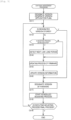
- Version designation section 72 of management device 70 firstly designates versions of software that are applied individually to the multiple mounting processes (S11).
- version designation section 72 designates versions that are applied individually to the mounting processes based on production plan M1, function information M3, and application information M4, which record types of the mounting processes, and prepares version application plan M5 as shown in Table 5 in Fig. 3 .
- application information M4 since first mounting process (P1) is a process of producing product type (U1) and a dedicated operation is necessary, a version is designated so that Ver2.1 is applied to first mounting process (P1) based on function information M3.
- updating section 73 determines whether a version of software suitable for the next mounting process is stored in control device 50 (S12). For example, if a designated version of software executed in a next mounting process (P1) is Ver2.1 and the designated version of software is not stored in current control device 50 (S12: No), updating section 73 determines whether a mounting process is being executed (S13). If control device50 is executing the mounting process (S13: Yes), updating section 73 detects a next low load period in the mounting process (S14).
- the low load period includes, for example, an execution period of a board conveyance process or a maintenance process.
- a board conveyance process is a process of conveying out or unloading a board on which components are mounted completely after a series of PP cycles are executed in a mounting process and conveying in or loading a new board.
- a maintenance process is a process of executing measurements to see whether a mechanical error is generated to thereby execute a calibration as required in order to maintain a proper operation of a constitutive device when the number of times of execution of the PP cycles reaches a defined count number or an operation time of a predetermined constitutive device reaches a defined time.
- the board conveyance process and the maintenance process are a process not involving an operation of mounting head 33 or a process which is easier and simpler than an operation performed in the PP cycles even when the process involves an operation of mounting head 33, and a processing load in various constitutive devices such as control device 50 is small.
- Updating section 73 estimates, for example, a degree of progress in the current mounting process based on a control program and detects a low load period which is long enough to secure a sufficient time to update the software currently and afterwards.
- the low load period may be a single continuous period or a period made up of multiple periods.
- updating section 73 executes an updating process of the software (S15).
- management device 70 transmits a designated version of software by communicating with control device 50 of component mounter 2.
- Control device 50 causes the software so inputted to be stored in a predetermined activation region.
- an activation region where to store the new software if control device 50 is executing the mounting process (S13: Yes), a different activation region is designated which differs from the activation region which is used in the mounting process and hence stores the software which is being executed in the mounting process in question. Additionally, as an activation region where to store the new software, if control device 50 is not executing the mounting process (S13: No), an activation region is designated which differs from the activation region where a version of software is stored which is to be used first in a mounting process from a next time onwards.
- Updating section 73 designates first activation region 51 or second activation region 52 of control device 50 based on version application plan M5 and causes new software to be stored in the designated activation region. As a result, the software of, for example, first activation region 51 is updated from Ver2.0 to Ver2.1. Updating section 73 updates version information M2 as indicated by a shaded section in Table 2-2 in Fig. 4 after the updating process of the software is finished (S16).
- version designation section 72 designates a version of software to be used in a scheduled mounting process before the mounting process is started to be executed (S17). Specifically speaking, version designation section 72 designates a version of software for use in the mounting process by selecting one of the multiple versions (Ver2.1, Ver4.0) stored in control device 50. As a result, if the scheduled mounting process is started (S18), control device 50 executes the software stored in, for example, first activation region 51.
- Management device 70 determines based on the production plan whether the mounting process which is being executed is a last process (S19). If the mounting process which is being executed is not a last process, (S19: No), management device 70 repeats the processing operations in S12 to S18.
- the version (Ver4.0) of software which is to be applied or used in second mounting process (P2) and third mounting process (P3) has already been stored in second activation region 52 of control device 50.
- a version (Ver3.2) of software which is to be used in fourth mounting process (P4) has been stored in neither of the activation regions.
- updating section 73 updates the software in first activation region 51 to the version (Ver3.2) of software which is scheduled to be used during execution of second mounting process (P2) or during execution of third mounting process (P3) (S15). Further, updating section 73 updates version information M2 as indicated by a shaded section in Table 2-3 in Fig. 4 after the updating process of the software is finished (S16). If the mounting process which is being executed is a final process (S19: Yes), management device 70 ends the management processing of the software.
- Management device 70 for a board work machine (component mounter 2) described above includes storage device 71 which stores version information M2 in which the current version of software (firmware) executed by control device 50 of component mounter 2 in the production process (the mounting process) is associated individually with multiple control devices 50 and version designation section 72 which designates a version of software to be applied or used in the production process based on the type of the production process and version information M2.
- management device 70 which is an external device of component mounter 2
- management device 70 can mange versions of software, whereby the manageability of component mounter 2 is improved.
- management device 70 designates a version of software which is to be used for a mounting process based on version information M2.
- component mounter 2 can control various operations using designated versions of software suitable for a mounting process. As a result, production efficiency can be improved.
- control device 50 which is a constitutive device
- the software is described as being firmware installed into control device 50.
- the software may be software stored in advance in, for example, a predetermined activation region of storage device 71 of management device 70. Then, control device 50 communicates with management device 70, which is the external device, via the network and executes the software stored in the predetermined activation region.
- version designation section 72 designates a version of software for use in a mounting process based on a type of the mounting process by storing in advance predetermined versions of software in the activation regions. Additionally, in the event that a version of software to be used is not stored in the predetermined activation region, for example, updating section 73 can cope with this event by updating the software as required.
- control device 50 of component mounter 2 executes the software stored in the predetermined activation region of storage device 71 of management device 70 via the network.
- a version of software to be used in the mounting process can be designated by setting a version of software to be stored in the activation region as required.
- the production efficiency can be improved.
- a configuration may be adopted in which multiple versions of software which differ from each other are stored in advance in multiple activation regions in storage device 71.
- This configuration is similar to the configuration of the embodiment in which the versions of software which differ from each other are stored in advance in first activation region 51 and second activation region 52 of control device 50, which is the constitutive device, and therefore, a detailed description of the configuration will be omitted here.
- Main differences between these configurations are in that the storage devices for storing the software differ, and in that whether control device 50, which is the constitutive device, executes the software via the network.
- version designation section 72 designates a version of software which is to be applied or used for a mounting process based on a type of the mounting process by causing control device 50 to activate the software stored in one of the multiple activation regions thereof.
- version designation section 72 designates a version of software which is to be applied or used for a mounting process based on a type of the mounting process by causing control device 50 to activate the software stored in one of the multiple activation regions thereof.
- version designation section 72 can switch the versions of software that control device 50 executes by setting the activation region accordingly.
- software suitable for a mounting process which is scheduled to be executed can be stored in a predetermined activation region in advance, whereby versions can individually designated for multiple control devices 50.
- version designation section 72 may substantially designate a version by causing updating section 73 to update the software stored in the activation region in question in advance.
- version designation section 72 is described as designating a version of software to be applied or used for a mounting process based on production plan M1, function information M3, and application information M4.
- version designation section 72 may set a version that it designates using various methods.
- version designation section 72 may recognize the current version based on version information M2 to designate a latest version or may designate a version set by the operator or managing person.
- control device 50 or storage device 71 of management device 70 is described as being configured to cause the two versions, differing from each other, of software to be stored.
- a configuration may be adopted in which three or more versions of software are stored in advance in control device 50 or management device 70, and version designation section 72 designates one of the three or more versions. With this configuration, a more precise version switching can be effected without involving any updating process.
- management device 70 is described as being incorporated in host computer 60.
- management device 70 can adopt other various forms in addition to host computer 60, as long as management device 70 constitutes an external device of component mounter 2, which is a board work machine.
- management device 70 may be a management dedicated device set in an assembly plant for board products or a server connected with a board work machine for communication via Internet. With any one of the configurations described above, the same working effect as that of the embodiment can be provided.
- the constitutive device into which the software is programmed is described as being control device 50 of component mounter 2.
- the constitutive device may be, for example, board conveyance device 10, mounting head 33, or the like in addition to control device 50, provided that the constitutive device makes up component mounter 2.
- component mounter 2 which is a board work machine, constitutes a managing target of management device 70.
- other board work machines than component mounter 2 may constitute a managing target of management device 70.
- management device 70 is described as designating a common version for multiple production lines L1 to L3, provided production lines L1 to L3 are the same production line in terms of configuration.
- management device 70 may manage individually multiple board work machines so as to permit them to have different versions.
- a configuration may be adopted in which management device 70 executes a simultaneous management of the individual production lines and an individual management of board work machines in a complex fashion and switches the management between the simultaneous management and the individual management as required. As a result, the manageability of the board work machine can be improved.
Landscapes
- Engineering & Computer Science (AREA)
- Theoretical Computer Science (AREA)
- Software Systems (AREA)
- General Engineering & Computer Science (AREA)
- Physics & Mathematics (AREA)
- General Physics & Mathematics (AREA)
- Computer Security & Cryptography (AREA)
- Automation & Control Theory (AREA)
- Operations Research (AREA)
- Manufacturing & Machinery (AREA)
- Microelectronics & Electronic Packaging (AREA)
- Supply And Installment Of Electrical Components (AREA)
- Stored Programmes (AREA)
- General Factory Administration (AREA)
Claims (7)
- Verwaltungsvorrichtung (70) für eine Leiterplattenbearbeitungsmaschine (2), umfassend:eine Speichervorrichtung (71), die Versionsinformationen speichert, in denen eine aktuelle Version einer Software, die von einer konstitutiven Vorrichtung einer Leiterplattenbearbeitungsmaschine (2) in einem Produktionsprozess ausgeführt wird, individuell mit den mehreren konstitutiven Vorrichtungen verknüpft ist, wobeikonstitutive Vorrichtungen einer Leiterplattenbearbeitungsmaschine (2) Vorrichtungen sind, aus denen die Leiterplattenbearbeitungsmaschine (2) besteht,dadurch gekennzeichnet, dassmehrere Versionen der Software, die sich voneinander unterscheiden, im Voraus in der Leiterplattenbearbeitungsmaschine (2) installiert werden; undeinen Versionsbestimmungsabschnitt (72), der so konfiguriert ist, dass er eine Version der Software bestimmt, die auf den Produktionsprozess anzuwenden ist, indem er eine der mehreren Versionen der in der Leiterplattenbearbeitungsmaschine (2) installierten Software auf der Grundlage eines Typs des Produktionsprozesses und der Versionsinformationen auswählt.
- Verwaltungsvorrichtung (70) für eine Leiterplattenbearbeitungsmaschine (2) nach Anspruch 1, wobei die Speichervorrichtung (71) ferner speichert:Funktionsinformationen, in denen eine Funktion der Software individuell mit mehreren Versionen verknüpft ist; undAnwendungsinformationen, in denen Funktionen der Software, die im Produktionsprozess benötigt werden, individuell mit Typen des Produktionsprozesses verknüpft sind, und wobeider Versionsbestimmungsabschnitt (72) so konfiguriert ist, dass er eine Version der Software, die auf den Produktionsprozess anzuwenden ist, auf der Grundlage eines Produktionsplans, in dem Typen von Produktionsprozessen, die zur Ausführung geplant sind, aufgezeichnet sind, der Funktionsinformationen und der Anwendungsinformationen bestimmt.
- Verwaltungsvorrichtung (70) für eine Leiterplattenbearbeitungsmaschine (2) nach Anspruch 1 oder 2, wobei die Verwaltungsvorrichtung (70) ferner einen Aktualisierungsabschnitt (73) umfasst, der so konfiguriert ist, dass er die andere der mehreren Versionen der Software aktualisiert, wenn die konstitutive Vorrichtung eine der mehreren Versionen der Software ausführt.
- Verwaltungsvorrichtung (70) für eine Leiterplattenbearbeitungsmaschine (2) nach Anspruch 3, wobei der Aktualisierungsabschnitt (73) so konfiguriert ist, dass er die Version der Software, die der Aktualisierungsabschnitt (73) aktualisieren soll, auf der Grundlage des Produktionsplans festlegt, in dem die Arten des Produktionsprozesses, dessen Ausführung geplant ist, aufgezeichnet sind.
- Verwaltungsvorrichtung (70) für eine Leiterplattenbearbeitungsmaschine (2) nach Anspruch 3 oder 4, wobei die Leiterplattenbearbeitungsmaschine (2) eine Bauteilbestückungsmaschine ist, die einen Bestückungsprozess ausführt, der einen Prozess der Wiederholung eines Aufnahme- und Bestückungszyklus umfasst, bei dem ein zugeführtes Bauteil aufgenommen und das so aufgenommene Bauteil als Produktionsprozess auf einer Leiterplatte montiert wird, und wobei
der Aktualisierungsabschnitt (73) so konfiguriert ist, dass er die Software während einer Periode geringer Last im Bestückungsprozess aktualisiert, wenn eine Verarbeitungslast der konstitutiven Vorrichtung stärker reduziert ist als während der Ausführung des Aufnahme- und Bestückungszyklus. - Verwaltungsvorrichtung (70) für eine Leiterplattenbearbeitungsmaschine (2) nach Anspruch 1 oder 2, wobeidie konstitutive Vorrichtung so konfiguriert ist, dass sie die Software ausführt, die im Voraus in einem vorbestimmten Aktivierungsbereich der Speichervorrichtung (71) gespeichert wurde, undwobei der Versionsbestimmungsabschnitt (72) so konfiguriert ist, dass er die Version der Software, die auf den Produktionsprozess angewendet werden soll, auf der Grundlage eines Typs des Produktionsprozesses bestimmt, indem er die Software der vorbestimmten Version im Voraus in dem Aktivierungsbereich speichert.
- Verwaltungsvorrichtung (70) für eine Leiterplattenbearbeitungsmaschine (2) nach Anspruch 6, wobei mehrere Versionen wie die Version, die sich voneinander unterscheiden, der Software im Voraus in mehreren Aktivierungsbereichen wie dem Aktivierungsbereich der Speichervorrichtung (71) gespeichert werden, und wobei
der Versionsbestimmungsabschnitt (72) so konfiguriert ist, dass er die Version der Software, die auf den Produktionsprozess anzuwenden ist, auf der Grundlage eines Typs des Produktionsprozesses bestimmt, indem er die konstitutive Vorrichtung veranlasst, die in einem der mehreren Aktivierungsbereiche gespeicherte Software zu aktivieren.
Applications Claiming Priority (1)
| Application Number | Priority Date | Filing Date | Title |
|---|---|---|---|
| PCT/JP2018/013315 WO2019186917A1 (ja) | 2018-03-29 | 2018-03-29 | 対基板作業機の管理装置 |
Publications (3)
| Publication Number | Publication Date |
|---|---|
| EP3780926A1 EP3780926A1 (de) | 2021-02-17 |
| EP3780926A4 EP3780926A4 (de) | 2021-04-07 |
| EP3780926B1 true EP3780926B1 (de) | 2023-05-31 |
Family
ID=68062609
Family Applications (1)
| Application Number | Title | Priority Date | Filing Date |
|---|---|---|---|
| EP18911641.1A Active EP3780926B1 (de) | 2018-03-29 | 2018-03-29 | Vorrichtung zur verwaltung einer substratverarbeitungsmaschine |
Country Status (5)
| Country | Link |
|---|---|
| US (1) | US11288057B2 (de) |
| EP (1) | EP3780926B1 (de) |
| JP (4) | JP6952874B2 (de) |
| CN (1) | CN111886940B (de) |
| WO (1) | WO2019186917A1 (de) |
Families Citing this family (3)
| Publication number | Priority date | Publication date | Assignee | Title |
|---|---|---|---|---|
| KR102926302B1 (ko) * | 2021-01-08 | 2026-02-11 | 엘지전자 주식회사 | 압축기 및 이를 구비하는 공기조화기 |
| JP7775755B2 (ja) * | 2022-03-14 | 2025-11-26 | オムロン株式会社 | ソフトウェア更新支援装置、検査システム管理装置及び検査システム |
| WO2023238180A1 (ja) * | 2022-06-06 | 2023-12-14 | 株式会社Fuji | 基板生産機および基板生産ライン |
Family Cites Families (13)
| Publication number | Priority date | Publication date | Assignee | Title |
|---|---|---|---|---|
| JPH11163600A (ja) * | 1997-11-25 | 1999-06-18 | Matsushita Electric Ind Co Ltd | リード上下曲がり検出方法 |
| JP4384439B2 (ja) * | 2002-11-21 | 2009-12-16 | 富士機械製造株式会社 | 対基板作業機、対基板作業システムおよび対基板作業機用作業ヘッド使用準備処理プログラム |
| JP2006092469A (ja) * | 2004-09-27 | 2006-04-06 | Nec Corp | プログラム更新方式、方法、およびシステム、並びに更新プログラム |
| CN101395668A (zh) * | 2006-04-07 | 2009-03-25 | 三星电子株式会社 | 信息记录介质、以及再现介质和装置 |
| JP4743133B2 (ja) * | 2007-02-19 | 2011-08-10 | パナソニック株式会社 | 電子部品実装用装置および電子部品実装用装置における制御プログラムの更新方法 |
| JP2009294894A (ja) | 2008-06-05 | 2009-12-17 | Brother Ind Ltd | プリンタ動作制御方法、プリンタ、およびプリンタシステム |
| JP4722973B2 (ja) * | 2008-08-12 | 2011-07-13 | 株式会社日立製作所 | リクエスト処理方法及び計算機システム |
| JP4751456B2 (ja) | 2009-02-04 | 2011-08-17 | ヤマハ発動機株式会社 | 表面実装機および部品供給装置のデータ送信システム |
| JP6334579B2 (ja) * | 2014-02-13 | 2018-05-30 | 株式会社Fuji | 基板生産装置の管理装置および管理方法 |
| JP6449901B2 (ja) * | 2014-10-22 | 2019-01-09 | 株式会社Fuji | フィーダの管理装置および管理方法 |
| JP2017187996A (ja) * | 2016-04-07 | 2017-10-12 | 富士機械製造株式会社 | フィーダの管理装置および管理方法 |
| CN106557347B (zh) * | 2016-11-24 | 2020-09-04 | 泰康保险集团股份有限公司 | 软件更新方法及装置 |
| JP6894266B2 (ja) * | 2017-03-09 | 2021-06-30 | Necプラットフォームズ株式会社 | 情報処理装置、管理制御装置のプログラム更新制御方法及びプログラム更新制御プログラム |
-
2018
- 2018-03-29 WO PCT/JP2018/013315 patent/WO2019186917A1/ja not_active Ceased
- 2018-03-29 CN CN201880091456.XA patent/CN111886940B/zh active Active
- 2018-03-29 JP JP2020508720A patent/JP6952874B2/ja active Active
- 2018-03-29 EP EP18911641.1A patent/EP3780926B1/de active Active
- 2018-03-29 US US17/042,710 patent/US11288057B2/en active Active
-
2021
- 2021-08-05 JP JP2021129207A patent/JP7042952B2/ja active Active
- 2021-08-05 JP JP2021129208A patent/JP7029569B2/ja active Active
-
2022
- 2022-03-15 JP JP2022040109A patent/JP2022079505A/ja active Pending
Also Published As
| Publication number | Publication date |
|---|---|
| US20210055923A1 (en) | 2021-02-25 |
| JP2021180046A (ja) | 2021-11-18 |
| WO2019186917A1 (ja) | 2019-10-03 |
| JP2022079505A (ja) | 2022-05-26 |
| JP7042952B2 (ja) | 2022-03-28 |
| JPWO2019186917A1 (ja) | 2020-12-03 |
| EP3780926A4 (de) | 2021-04-07 |
| JP2021180045A (ja) | 2021-11-18 |
| US11288057B2 (en) | 2022-03-29 |
| JP6952874B2 (ja) | 2021-10-27 |
| EP3780926A1 (de) | 2021-02-17 |
| JP7029569B2 (ja) | 2022-03-03 |
| CN111886940A (zh) | 2020-11-03 |
| CN111886940B (zh) | 2022-02-11 |
Similar Documents
| Publication | Publication Date | Title |
|---|---|---|
| US9811078B2 (en) | Method for providing instruction on setup changeover work in component mounting system, and component mounting system | |
| US12048100B2 (en) | Management device, mobile work device, mounting system, and management method | |
| JP6334579B2 (ja) | 基板生産装置の管理装置および管理方法 | |
| EP3843517B1 (de) | Mobile arbeitsmanagementvorrichtung, mobile arbeitsvorrichtung, montagesystem und mobiles arbeitsmanagementverfahren | |
| JP7042952B2 (ja) | ソフトウェア更新方法および生産システム | |
| KR101489703B1 (ko) | 전자 부품의 실장 방법, 및 표면 실장기 | |
| US12041726B2 (en) | Management device, moving work device, mounting device, mounting system, and management method | |
| JP6449901B2 (ja) | フィーダの管理装置および管理方法 | |
| JP2017187996A (ja) | フィーダの管理装置および管理方法 | |
| JP7292459B2 (ja) | ソフトウェア更新方法 | |
| JP2014241328A (ja) | 電子部品装着機 | |
| JP7217348B2 (ja) | 対基板作業機の管理装置および管理システム | |
| JP2004063940A (ja) | 電子回路部品装着方法および電子回路部品装着システム | |
| CN102036546A (zh) | 电路板装配作业装置及电路板装配作业装置中的控制方法 | |
| CN107114007B (zh) | 电子元件供给系统 | |
| CN109328488B (zh) | 电子元件供给装置 | |
| JP7483051B2 (ja) | データ管理システム | |
| EP3829285B1 (de) | Arbeitsunterstützungsvorrichtung und substratbearbeitungsmaschine | |
| KR20080003634A (ko) | 표면실장용 테이프, 표면실장 시스템 및 이를 이용한표면실장 방법 | |
| WO2025173156A1 (ja) | 生産支援装置および生産支援方法 | |
| CN119896053A (zh) | 元件安装系统 | |
| CN102045997A (zh) | 基板组装封装线的管理方法 | |
| US20210219478A1 (en) | Determination device and component mounting apparatus having same |
Legal Events
| Date | Code | Title | Description |
|---|---|---|---|
| STAA | Information on the status of an ep patent application or granted ep patent |
Free format text: STATUS: THE INTERNATIONAL PUBLICATION HAS BEEN MADE |
|
| PUAI | Public reference made under article 153(3) epc to a published international application that has entered the european phase |
Free format text: ORIGINAL CODE: 0009012 |
|
| STAA | Information on the status of an ep patent application or granted ep patent |
Free format text: STATUS: REQUEST FOR EXAMINATION WAS MADE |
|
| 17P | Request for examination filed |
Effective date: 20200916 |
|
| AK | Designated contracting states |
Kind code of ref document: A1 Designated state(s): AL AT BE BG CH CY CZ DE DK EE ES FI FR GB GR HR HU IE IS IT LI LT LU LV MC MK MT NL NO PL PT RO RS SE SI SK SM TR |
|
| AX | Request for extension of the european patent |
Extension state: BA ME |
|
| A4 | Supplementary search report drawn up and despatched |
Effective date: 20210304 |
|
| RIC1 | Information provided on ipc code assigned before grant |
Ipc: H05K 13/00 20060101AFI20210226BHEP Ipc: H05K 13/08 20060101ALI20210226BHEP |
|
| DAV | Request for validation of the european patent (deleted) | ||
| DAX | Request for extension of the european patent (deleted) | ||
| GRAP | Despatch of communication of intention to grant a patent |
Free format text: ORIGINAL CODE: EPIDOSNIGR1 |
|
| STAA | Information on the status of an ep patent application or granted ep patent |
Free format text: STATUS: GRANT OF PATENT IS INTENDED |
|
| INTG | Intention to grant announced |
Effective date: 20230216 |
|
| GRAS | Grant fee paid |
Free format text: ORIGINAL CODE: EPIDOSNIGR3 |
|
| GRAA | (expected) grant |
Free format text: ORIGINAL CODE: 0009210 |
|
| STAA | Information on the status of an ep patent application or granted ep patent |
Free format text: STATUS: THE PATENT HAS BEEN GRANTED |
|
| AK | Designated contracting states |
Kind code of ref document: B1 Designated state(s): AL AT BE BG CH CY CZ DE DK EE ES FI FR GB GR HR HU IE IS IT LI LT LU LV MC MK MT NL NO PL PT RO RS SE SI SK SM TR |
|
| REG | Reference to a national code |
Ref country code: GB Ref legal event code: FG4D Ref country code: CH Ref legal event code: EP |
|
| REG | Reference to a national code |
Ref country code: DE Ref legal event code: R096 Ref document number: 602018050609 Country of ref document: DE |
|
| P01 | Opt-out of the competence of the unified patent court (upc) registered |
Effective date: 20230328 |
|
| REG | Reference to a national code |
Ref country code: AT Ref legal event code: REF Ref document number: 1571815 Country of ref document: AT Kind code of ref document: T Effective date: 20230615 |
|
| REG | Reference to a national code |
Ref country code: IE Ref legal event code: FG4D |
|
| REG | Reference to a national code |
Ref country code: LT Ref legal event code: MG9D |
|
| REG | Reference to a national code |
Ref country code: NL Ref legal event code: MP Effective date: 20230531 |
|
| REG | Reference to a national code |
Ref country code: AT Ref legal event code: MK05 Ref document number: 1571815 Country of ref document: AT Kind code of ref document: T Effective date: 20230531 |
|
| PG25 | Lapsed in a contracting state [announced via postgrant information from national office to epo] |
Ref country code: SE Free format text: LAPSE BECAUSE OF FAILURE TO SUBMIT A TRANSLATION OF THE DESCRIPTION OR TO PAY THE FEE WITHIN THE PRESCRIBED TIME-LIMIT Effective date: 20230531 Ref country code: NO Free format text: LAPSE BECAUSE OF FAILURE TO SUBMIT A TRANSLATION OF THE DESCRIPTION OR TO PAY THE FEE WITHIN THE PRESCRIBED TIME-LIMIT Effective date: 20230831 Ref country code: ES Free format text: LAPSE BECAUSE OF FAILURE TO SUBMIT A TRANSLATION OF THE DESCRIPTION OR TO PAY THE FEE WITHIN THE PRESCRIBED TIME-LIMIT Effective date: 20230531 Ref country code: AT Free format text: LAPSE BECAUSE OF FAILURE TO SUBMIT A TRANSLATION OF THE DESCRIPTION OR TO PAY THE FEE WITHIN THE PRESCRIBED TIME-LIMIT Effective date: 20230531 |
|
| PG25 | Lapsed in a contracting state [announced via postgrant information from national office to epo] |
Ref country code: RS Free format text: LAPSE BECAUSE OF FAILURE TO SUBMIT A TRANSLATION OF THE DESCRIPTION OR TO PAY THE FEE WITHIN THE PRESCRIBED TIME-LIMIT Effective date: 20230531 Ref country code: PL Free format text: LAPSE BECAUSE OF FAILURE TO SUBMIT A TRANSLATION OF THE DESCRIPTION OR TO PAY THE FEE WITHIN THE PRESCRIBED TIME-LIMIT Effective date: 20230531 Ref country code: NL Free format text: LAPSE BECAUSE OF FAILURE TO SUBMIT A TRANSLATION OF THE DESCRIPTION OR TO PAY THE FEE WITHIN THE PRESCRIBED TIME-LIMIT Effective date: 20230531 Ref country code: LV Free format text: LAPSE BECAUSE OF FAILURE TO SUBMIT A TRANSLATION OF THE DESCRIPTION OR TO PAY THE FEE WITHIN THE PRESCRIBED TIME-LIMIT Effective date: 20230531 Ref country code: LT Free format text: LAPSE BECAUSE OF FAILURE TO SUBMIT A TRANSLATION OF THE DESCRIPTION OR TO PAY THE FEE WITHIN THE PRESCRIBED TIME-LIMIT Effective date: 20230531 Ref country code: IS Free format text: LAPSE BECAUSE OF FAILURE TO SUBMIT A TRANSLATION OF THE DESCRIPTION OR TO PAY THE FEE WITHIN THE PRESCRIBED TIME-LIMIT Effective date: 20230930 Ref country code: HR Free format text: LAPSE BECAUSE OF FAILURE TO SUBMIT A TRANSLATION OF THE DESCRIPTION OR TO PAY THE FEE WITHIN THE PRESCRIBED TIME-LIMIT Effective date: 20230531 Ref country code: GR Free format text: LAPSE BECAUSE OF FAILURE TO SUBMIT A TRANSLATION OF THE DESCRIPTION OR TO PAY THE FEE WITHIN THE PRESCRIBED TIME-LIMIT Effective date: 20230901 |
|
| PG25 | Lapsed in a contracting state [announced via postgrant information from national office to epo] |
Ref country code: FI Free format text: LAPSE BECAUSE OF FAILURE TO SUBMIT A TRANSLATION OF THE DESCRIPTION OR TO PAY THE FEE WITHIN THE PRESCRIBED TIME-LIMIT Effective date: 20230531 |
|
| PG25 | Lapsed in a contracting state [announced via postgrant information from national office to epo] |
Ref country code: SK Free format text: LAPSE BECAUSE OF FAILURE TO SUBMIT A TRANSLATION OF THE DESCRIPTION OR TO PAY THE FEE WITHIN THE PRESCRIBED TIME-LIMIT Effective date: 20230531 |
|
| PG25 | Lapsed in a contracting state [announced via postgrant information from national office to epo] |
Ref country code: SM Free format text: LAPSE BECAUSE OF FAILURE TO SUBMIT A TRANSLATION OF THE DESCRIPTION OR TO PAY THE FEE WITHIN THE PRESCRIBED TIME-LIMIT Effective date: 20230531 Ref country code: SK Free format text: LAPSE BECAUSE OF FAILURE TO SUBMIT A TRANSLATION OF THE DESCRIPTION OR TO PAY THE FEE WITHIN THE PRESCRIBED TIME-LIMIT Effective date: 20230531 Ref country code: RO Free format text: LAPSE BECAUSE OF FAILURE TO SUBMIT A TRANSLATION OF THE DESCRIPTION OR TO PAY THE FEE WITHIN THE PRESCRIBED TIME-LIMIT Effective date: 20230531 Ref country code: PT Free format text: LAPSE BECAUSE OF FAILURE TO SUBMIT A TRANSLATION OF THE DESCRIPTION OR TO PAY THE FEE WITHIN THE PRESCRIBED TIME-LIMIT Effective date: 20231002 Ref country code: EE Free format text: LAPSE BECAUSE OF FAILURE TO SUBMIT A TRANSLATION OF THE DESCRIPTION OR TO PAY THE FEE WITHIN THE PRESCRIBED TIME-LIMIT Effective date: 20230531 Ref country code: DK Free format text: LAPSE BECAUSE OF FAILURE TO SUBMIT A TRANSLATION OF THE DESCRIPTION OR TO PAY THE FEE WITHIN THE PRESCRIBED TIME-LIMIT Effective date: 20230531 Ref country code: CZ Free format text: LAPSE BECAUSE OF FAILURE TO SUBMIT A TRANSLATION OF THE DESCRIPTION OR TO PAY THE FEE WITHIN THE PRESCRIBED TIME-LIMIT Effective date: 20230531 |
|
| REG | Reference to a national code |
Ref country code: DE Ref legal event code: R097 Ref document number: 602018050609 Country of ref document: DE |
|
| PLBE | No opposition filed within time limit |
Free format text: ORIGINAL CODE: 0009261 |
|
| STAA | Information on the status of an ep patent application or granted ep patent |
Free format text: STATUS: NO OPPOSITION FILED WITHIN TIME LIMIT |
|
| PG25 | Lapsed in a contracting state [announced via postgrant information from national office to epo] |
Ref country code: SI Free format text: LAPSE BECAUSE OF FAILURE TO SUBMIT A TRANSLATION OF THE DESCRIPTION OR TO PAY THE FEE WITHIN THE PRESCRIBED TIME-LIMIT Effective date: 20230531 |
|
| 26N | No opposition filed |
Effective date: 20240301 |
|
| PG25 | Lapsed in a contracting state [announced via postgrant information from national office to epo] |
Ref country code: SI Free format text: LAPSE BECAUSE OF FAILURE TO SUBMIT A TRANSLATION OF THE DESCRIPTION OR TO PAY THE FEE WITHIN THE PRESCRIBED TIME-LIMIT Effective date: 20230531 Ref country code: IT Free format text: LAPSE BECAUSE OF FAILURE TO SUBMIT A TRANSLATION OF THE DESCRIPTION OR TO PAY THE FEE WITHIN THE PRESCRIBED TIME-LIMIT Effective date: 20230531 |
|
| REG | Reference to a national code |
Ref country code: CH Ref legal event code: PL |
|
| PG25 | Lapsed in a contracting state [announced via postgrant information from national office to epo] |
Ref country code: BG Free format text: LAPSE BECAUSE OF FAILURE TO SUBMIT A TRANSLATION OF THE DESCRIPTION OR TO PAY THE FEE WITHIN THE PRESCRIBED TIME-LIMIT Effective date: 20230531 |
|
| PG25 | Lapsed in a contracting state [announced via postgrant information from national office to epo] |
Ref country code: LU Free format text: LAPSE BECAUSE OF NON-PAYMENT OF DUE FEES Effective date: 20240329 |
|
| PG25 | Lapsed in a contracting state [announced via postgrant information from national office to epo] |
Ref country code: MC Free format text: LAPSE BECAUSE OF FAILURE TO SUBMIT A TRANSLATION OF THE DESCRIPTION OR TO PAY THE FEE WITHIN THE PRESCRIBED TIME-LIMIT Effective date: 20230531 |
|
| GBPC | Gb: european patent ceased through non-payment of renewal fee |
Effective date: 20240329 |
|
| PG25 | Lapsed in a contracting state [announced via postgrant information from national office to epo] |
Ref country code: MC Free format text: LAPSE BECAUSE OF FAILURE TO SUBMIT A TRANSLATION OF THE DESCRIPTION OR TO PAY THE FEE WITHIN THE PRESCRIBED TIME-LIMIT Effective date: 20230531 Ref country code: LU Free format text: LAPSE BECAUSE OF NON-PAYMENT OF DUE FEES Effective date: 20240329 Ref country code: BG Free format text: LAPSE BECAUSE OF FAILURE TO SUBMIT A TRANSLATION OF THE DESCRIPTION OR TO PAY THE FEE WITHIN THE PRESCRIBED TIME-LIMIT Effective date: 20230531 |
|
| REG | Reference to a national code |
Ref country code: BE Ref legal event code: MM Effective date: 20240331 |
|
| PG25 | Lapsed in a contracting state [announced via postgrant information from national office to epo] |
Ref country code: BE Free format text: LAPSE BECAUSE OF NON-PAYMENT OF DUE FEES Effective date: 20240331 |
|
| PG25 | Lapsed in a contracting state [announced via postgrant information from national office to epo] |
Ref country code: GB Free format text: LAPSE BECAUSE OF NON-PAYMENT OF DUE FEES Effective date: 20240329 |
|
| PG25 | Lapsed in a contracting state [announced via postgrant information from national office to epo] |
Ref country code: FR Free format text: LAPSE BECAUSE OF NON-PAYMENT OF DUE FEES Effective date: 20240331 |
|
| PG25 | Lapsed in a contracting state [announced via postgrant information from national office to epo] |
Ref country code: IE Free format text: LAPSE BECAUSE OF NON-PAYMENT OF DUE FEES Effective date: 20240329 |
|
| PG25 | Lapsed in a contracting state [announced via postgrant information from national office to epo] |
Ref country code: IE Free format text: LAPSE BECAUSE OF NON-PAYMENT OF DUE FEES Effective date: 20240329 Ref country code: GB Free format text: LAPSE BECAUSE OF NON-PAYMENT OF DUE FEES Effective date: 20240329 Ref country code: FR Free format text: LAPSE BECAUSE OF NON-PAYMENT OF DUE FEES Effective date: 20240331 Ref country code: BE Free format text: LAPSE BECAUSE OF NON-PAYMENT OF DUE FEES Effective date: 20240331 Ref country code: CH Free format text: LAPSE BECAUSE OF NON-PAYMENT OF DUE FEES Effective date: 20240331 |
|
| PG25 | Lapsed in a contracting state [announced via postgrant information from national office to epo] |
Ref country code: CY Free format text: LAPSE BECAUSE OF FAILURE TO SUBMIT A TRANSLATION OF THE DESCRIPTION OR TO PAY THE FEE WITHIN THE PRESCRIBED TIME-LIMIT; INVALID AB INITIO Effective date: 20180329 |
|
| PG25 | Lapsed in a contracting state [announced via postgrant information from national office to epo] |
Ref country code: HU Free format text: LAPSE BECAUSE OF FAILURE TO SUBMIT A TRANSLATION OF THE DESCRIPTION OR TO PAY THE FEE WITHIN THE PRESCRIBED TIME-LIMIT; INVALID AB INITIO Effective date: 20180329 |
|
| PG25 | Lapsed in a contracting state [announced via postgrant information from national office to epo] |
Ref country code: TR Free format text: LAPSE BECAUSE OF FAILURE TO SUBMIT A TRANSLATION OF THE DESCRIPTION OR TO PAY THE FEE WITHIN THE PRESCRIBED TIME-LIMIT Effective date: 20230531 |
|
| PGFP | Annual fee paid to national office [announced via postgrant information from national office to epo] |
Ref country code: DE Payment date: 20260204 Year of fee payment: 9 |