EP3782974A1 - Verfahren und anlage zur herstellung von methanol aus synthesegasen mit hohem kohlendioxid-anteil - Google Patents
Verfahren und anlage zur herstellung von methanol aus synthesegasen mit hohem kohlendioxid-anteil Download PDFInfo
- Publication number
- EP3782974A1 EP3782974A1 EP19020480.0A EP19020480A EP3782974A1 EP 3782974 A1 EP3782974 A1 EP 3782974A1 EP 19020480 A EP19020480 A EP 19020480A EP 3782974 A1 EP3782974 A1 EP 3782974A1
- Authority
- EP
- European Patent Office
- Prior art keywords
- gas
- reactor
- methanol
- compressor stage
- stream
- Prior art date
- Legal status (The legal status is an assumption and is not a legal conclusion. Google has not performed a legal analysis and makes no representation as to the accuracy of the status listed.)
- Granted
Links
Images


Classifications
-
- C—CHEMISTRY; METALLURGY
- C07—ORGANIC CHEMISTRY
- C07C—ACYCLIC OR CARBOCYCLIC COMPOUNDS
- C07C29/00—Preparation of compounds having hydroxy or O-metal groups bound to a carbon atom not belonging to a six-membered aromatic ring
- C07C29/15—Preparation of compounds having hydroxy or O-metal groups bound to a carbon atom not belonging to a six-membered aromatic ring by reduction of oxides of carbon exclusively
- C07C29/151—Preparation of compounds having hydroxy or O-metal groups bound to a carbon atom not belonging to a six-membered aromatic ring by reduction of oxides of carbon exclusively with hydrogen or hydrogen-containing gases
- C07C29/152—Preparation of compounds having hydroxy or O-metal groups bound to a carbon atom not belonging to a six-membered aromatic ring by reduction of oxides of carbon exclusively with hydrogen or hydrogen-containing gases characterised by the reactor used
-
- C—CHEMISTRY; METALLURGY
- C07—ORGANIC CHEMISTRY
- C07C—ACYCLIC OR CARBOCYCLIC COMPOUNDS
- C07C29/00—Preparation of compounds having hydroxy or O-metal groups bound to a carbon atom not belonging to a six-membered aromatic ring
- C07C29/15—Preparation of compounds having hydroxy or O-metal groups bound to a carbon atom not belonging to a six-membered aromatic ring by reduction of oxides of carbon exclusively
- C07C29/151—Preparation of compounds having hydroxy or O-metal groups bound to a carbon atom not belonging to a six-membered aromatic ring by reduction of oxides of carbon exclusively with hydrogen or hydrogen-containing gases
- C07C29/1516—Multisteps
- C07C29/1518—Multisteps one step being the formation of initial mixture of carbon oxides and hydrogen for synthesis
-
- B—PERFORMING OPERATIONS; TRANSPORTING
- B01—PHYSICAL OR CHEMICAL PROCESSES OR APPARATUS IN GENERAL
- B01J—CHEMICAL OR PHYSICAL PROCESSES, e.g. CATALYSIS OR COLLOID CHEMISTRY; THEIR RELEVANT APPARATUS
- B01J19/00—Chemical, physical or physico-chemical processes in general; Their relevant apparatus
- B01J19/24—Stationary reactors without moving elements inside
- B01J19/245—Stationary reactors without moving elements inside placed in series
-
- B—PERFORMING OPERATIONS; TRANSPORTING
- B01—PHYSICAL OR CHEMICAL PROCESSES OR APPARATUS IN GENERAL
- B01J—CHEMICAL OR PHYSICAL PROCESSES, e.g. CATALYSIS OR COLLOID CHEMISTRY; THEIR RELEVANT APPARATUS
- B01J19/00—Chemical, physical or physico-chemical processes in general; Their relevant apparatus
- B01J19/24—Stationary reactors without moving elements inside
- B01J19/248—Reactors comprising multiple separated flow channels
-
- B—PERFORMING OPERATIONS; TRANSPORTING
- B01—PHYSICAL OR CHEMICAL PROCESSES OR APPARATUS IN GENERAL
- B01J—CHEMICAL OR PHYSICAL PROCESSES, e.g. CATALYSIS OR COLLOID CHEMISTRY; THEIR RELEVANT APPARATUS
- B01J2219/00—Chemical, physical or physico-chemical processes in general; Their relevant apparatus
- B01J2219/00002—Chemical plants
- B01J2219/00004—Scale aspects
- B01J2219/00006—Large-scale industrial plants
-
- B—PERFORMING OPERATIONS; TRANSPORTING
- B01—PHYSICAL OR CHEMICAL PROCESSES OR APPARATUS IN GENERAL
- B01J—CHEMICAL OR PHYSICAL PROCESSES, e.g. CATALYSIS OR COLLOID CHEMISTRY; THEIR RELEVANT APPARATUS
- B01J2219/00—Chemical, physical or physico-chemical processes in general; Their relevant apparatus
- B01J2219/00002—Chemical plants
- B01J2219/00027—Process aspects
- B01J2219/00033—Continuous processes
-
- B—PERFORMING OPERATIONS; TRANSPORTING
- B01—PHYSICAL OR CHEMICAL PROCESSES OR APPARATUS IN GENERAL
- B01J—CHEMICAL OR PHYSICAL PROCESSES, e.g. CATALYSIS OR COLLOID CHEMISTRY; THEIR RELEVANT APPARATUS
- B01J2219/00—Chemical, physical or physico-chemical processes in general; Their relevant apparatus
- B01J2219/00002—Chemical plants
- B01J2219/00027—Process aspects
- B01J2219/0004—Processes in series
-
- C—CHEMISTRY; METALLURGY
- C07—ORGANIC CHEMISTRY
- C07C—ACYCLIC OR CARBOCYCLIC COMPOUNDS
- C07C31/00—Saturated compounds having hydroxy or O-metal groups bound to acyclic carbon atoms
- C07C31/02—Monohydroxylic acyclic alcohols
- C07C31/04—Methanol
Definitions
- the invention relates to a method for producing methanol, a plant for producing methanol and the use of the plant according to the invention in a method according to the invention.
- methanol is usually produced from synthesis gas, a mixture of predominantly hydrogen (H 2 ), carbon monoxide (CO) and carbon dioxide (CO 2 ) in the so-called low-pressure process at pressures between 60 and 120 bar.
- synthesis gas a mixture of predominantly hydrogen (H 2 ), carbon monoxide (CO) and carbon dioxide (CO 2 ) in the so-called low-pressure process at pressures between 60 and 120 bar.
- CO carbon monoxide
- CO 2 carbon dioxide
- either one-stage or two-stage processes are used in relation to the reactor section of the process in order to convert the synthesis gas into methanol with a high yield.
- the synthesis gas which is usually generated at pressures between 20 and 40 bar, is first brought to the pressure of greater than 60 bar required for the reaction using a gas compressor (synthesis gas compressor).
- synthesis gas compressor gas compressor
- the processes also mostly work with high gas cycles in a so-called synthesis cycle, also known as a synthesis loop, in which synthesis gas not converted into methanol in the first reactor pass (per-pass) is returned to the reactor inlet as recycle gas, also known as recycle gas becomes.
- the synthesis cycle is necessary in order to achieve sufficiently high synthesis gas conversions and thus overall yields despite the low per-pass conversions.
- the amount of recirculated gas is up to 5 times higher than the amount of fresh gas supplied from the synthesis gas production, depending on the technology, fresh gas composition and reactor system. This is especially the case with synthesis gas or fresh gas compositions with a high CO 2 content, in which there is a significantly lower thermodynamic equilibrium conversion compared to more CO-rich synthesis gases.
- a dedicated cycle gas compressor is usually used to convey and compress the high gas cycle quantities.
- a disadvantage of these high recirculation rates is the accumulation of inert constituents, i.e. constituents that cannot be converted under the conditions of methanol synthesis, such as methane and nitrogen, which have to be removed from the synthesis cycle as purge gas, also known as purge gas. Hydrogen is usually also removed, which then has to be recovered in a complex manner, which is usually done with the help of an alternating pressure absorption device.
- the per-pass conversion can be increased over the total number of reactor stages and the recirculation rate can be reduced as a result.
- methane (CH 4 ) and nitrogen (N 2 ) further intensify this negative effect.
- the proportion of recycle gas can be reduced, but at the same time the number of process units required increases, which usually also increases investment costs (CAPEX). If a synthesis cycle is completely dispensed with ("oncethrough" process), the number of reactors required increases further, so that the absence of the synthesis cycle is again negatively compensated.
- synthesis gases with a high CO 2 content have increasingly come into focus.
- the generation of synthesis gases from carbon dioxide from exhaust gas sources by combining with hydrogen from water electrolysis is conceivable, whereby the electricity for the water electrolysis could come from renewable energy sources.
- Such a synthesis gas can be regarded as climate neutral, but contains very little or no carbon monoxide.
- a stoichiometric or slightly overstoichiometric ratio is usually set for the fresh gas.
- SN n H 2 - n CO 2 n CO + n CO 2 , with n in mol
- H 2 3 to 3.05 mol of hydrogen
- CO 2 carbon dioxide
- hydrogen comes from renewable energy sources and carbon dioxide from an exhaust gas source, hydrogen has the greatest impact on the economy of the process in question.
- One object of the present invention is to provide a method for producing methanol which at least partially overcomes the disadvantages of the prior art.
- Another object of the present invention is to provide a method for the production of methanol which enables savings in terms of the energy to be expended for the method, in particular for the operation of gas compressors.
- a further object of the present invention is to provide a method for the production of methanol which enables savings in terms of the plant parts to be provided for the method, in particular with regard to the number of compressor stages required.
- Another object of the present invention is to provide a method for producing methanol which largely avoids hydrogen losses via a purge gas flow (purge gas flow).
- a further object of the present invention is to provide a process for the production of methanol which reduces the catalyst load by a high partial pressure of water in the catalyst bed and extends the life of the catalysts used.
- Another object of the present invention is to provide a process for the production of methanol which reduces the amount of synthesis gas to be recycled in a synthesis cycle as far as possible.
- a further object of the present invention is to provide a plant for the production of methanol which at least partially solves at least one of the aforementioned objects.
- the recirculation gas is introduced into the second compressor stage together with the pre-compressed second fresh gas stream.
- the amount of recirculated gas is reduced by the catalytic conversion of the synthesis gas in a plurality of reactor stages arranged in series.
- recycle gas stream withdrawn from one or more reactor stages can be fed directly to the second compressor stage (together with the second fresh gas stream), which surprisingly reduces the overall compressor output required for the process.
- synthesis gas is converted into a product stream which contains methanol.
- This is a raw methanol which, in addition to methanol as such, can also contain water and other condensable by-products.
- the water content of the raw methanol increases with the concentration of carbon dioxide in the feed gas.
- Methanol is separated from the remaining synthesis gas stream by cooling and the resulting condensation, so that predominantly unreacted synthesis gas remains in the gas phase.
- This is fed into the following reactor stages arranged in series.
- the last of the reactor stages arranged in series is an exception.
- Unreacted synthesis gas withdrawn from the last of the reactor stages arranged in series is introduced into the second compressor stage as a recycle gas stream.
- a certain proportion of the recycle gas stream is separated off from the recycle gas stream as a purge gas stream.
- unreacted synthesis gas is at least partially withdrawn from at least one of the reactor stages as a recycle gas stream for introducing the recycle gas stream into the second compressor stage in accordance with step c).
- step e) methanol is at least partially separated from unreacted synthesis gas by cooling and condensation from the product stream obtained. A complete separation of methanol by cooling and condensation of unreacted synthesis gas is sought in order to shift the reaction equilibrium to the side of the product (methanol).
- a preferred embodiment of the method according to the invention is characterized in that the recycle gas stream is introduced into the second compressor stage after being drawn off according to step f) without prior compression.
- the return gas stream is preferably fed to the second compressor stage directly and without the use of a return gas compressor (recycle gas compressor), that is to say without the use of a further compressor stage for compressing the return gas.
- a return gas compressor recycle gas compressor
- This not only reduces the total required compressor output of the process (decrease in OPEX).
- CAEX investment costs
- only two compressor stages are required for the entire methanol synthesis, namely the first compressor stage to compress the first fresh gas to generate the second fresh gas, and the second compressor stage to compress the second fresh gas together with the recycle gas to synthesis pressure to generate the synthesis gas.
- a preferred embodiment of the process according to the invention is characterized in that, according to step e), unreacted synthesis gas is completely introduced into the respectively following reactor stages arranged in series.
- the maximum possible amount of unreacted synthesis gas is introduced into each of the following reactor stages arranged in series, which is to be understood here by "complete”.
- a small part of the unreacted synthesis gas is always dissolved in the condensate (methanol). Accordingly, this small part cannot be introduced into the following reactor stage.
- unreacted synthesis gas is only obtained in the last of the reactor stages arranged in series, and the amount of the recycle gas stream is reduced to a minimum.
- a preferred embodiment of the method according to the invention is thus further characterized in that, according to step f), unreacted synthesis gas is withdrawn from the last of the plurality of reactor stages arranged in series as a recycle gas stream, in particular is withdrawn exclusively from the last of the plurality of reactor stages arranged in series.
- a preferred embodiment of the method according to the invention is characterized in that the recycle gas stream and the second fresh gas stream are brought together and introduced into the second compressor stage as a combined gas stream.
- both streams are first mixed after they have been combined and then fed into the second compressor stage as a combined gas stream.
- the process according to the invention is particularly suitable for highly substoichiometric, high-carbon dioxide-containing synthesis gases to slightly above-stoichiometric high-carbon dioxide-containing feed gases.
- the feed gas has a stoichiometric number SN of 1.5 to 1.9, preferably 1.6 to 1.8.
- compositions according to the aforementioned stoichiometric number enable a further reduction in the overall required compressor output of the method according to the invention. If the stoichiometric number is lower than 2, and if the feed gas contains only carbon dioxide with regard to the carbon oxides, for example, the ratio of hydrogen to carbon dioxide is less than the (ideal) stoichiometric ratio of 3 to 1. Carbon dioxide is therefore in excess. This improves the hydrogen conversion, which also has a positive effect on the overall economy of the process. It can be assumed that compared to carbon dioxide, hydrogen is always the more expensive raw material, which means that hydrogen has a decisive influence on the cost-effectiveness of the process.
- the volume flows are understood to mean the standardized volume flows based on the physical standard state of the respective gas at 0 ° C and 1.01325 bar absolute pressure (standard volume flow).
- the recirculation rates according to the process according to the invention are very low due to the use of a plurality of reaction stages arranged in series with intermediate condensation.
- the recirculation rate can be further reduced with a constantly high hydrogen conversion, as studies have surprisingly shown. If the amount of the return gas flow is reduced further, in particular to values significantly less than 1, the total required compressor output also decreases accordingly.
- a preferred embodiment of the process according to the invention is characterized in that a carbon dioxide conversion of at least 80 mol% is achieved over the entirety of the plurality of reactor stages arranged in series, starting from the feed gas.
- the proportion of carbon dioxide converted over all reactor stages is preferably at least 80 mol%.
- the carbon dioxide conversion is particularly preferably at least 90 mol%, more preferably at least 95 mol% and further preferably at least 98 mol%.
- the hydrogen conversion is preferably at least 95 mol%, more preferably at least 98 mol% or at least 99 mol%.
- the highest possible hydrogen conversion should preferably be achieved, since in many cases hydrogen, in contrast to carbon dioxide, is the much more expensive raw material source.
- a preferred embodiment of the process according to the invention is characterized in that the majority of the reactor stages arranged in series comprises a number of 2 to 8 reactor stages.
- the optimum number of reactor stages depends on a large number of factors such as the amount of methanol to be produced, the conversion per reactor stage, composition of the feed gas and, if necessary, other factors.
- the investment costs increase with the number of reactor stages and the amount of the recycle gas stream decreases, as a result of which savings in terms of compressor power are particularly high.
- the investment costs decrease with the reduction in the number of reaction stages, but the amount of recycle gas flow increases, which means that the savings in terms of compressor power are lower.
- the plurality of reactor stages arranged in series therefore preferably comprises a number of 3 to 5 reactor stages, particularly preferably a number of 4 reactor stages. This achieves an optimal compromise in terms of investment costs and savings in compressor performance.
- the plant according to the invention is preceded by a production unit for generating a feed gas containing hydrogen (H 2 ) and carbon oxides.
- the feed gas has a proportion of at least 80% by volume of carbon dioxide (CO 2 ).
- the feed gas is fed to the system according to the invention as the first fresh gas.
- a preferred embodiment of the system according to the invention is characterized in that between the outlet for supplying unreacted synthesis gas as recirculation gas to the second compressor stage and the supply for introducing the recirculation gas into the second compressor stage, there is no compressor stage for previous compression of the recirculation gas before it is introduced into the second compressor stage is arranged.
- the unreacted synthesis gas after being drawn off from a reactor unit, is fed directly to the second compressor stage as recycle gas.
- no additional compressor stage is provided between the outlet of the reactor unit and the feed to the second compressor unit for compressing the recycle gas before it is fed to the second compressor stage.
- a preferred embodiment of the plant according to the invention is characterized in that an outlet for supplying unreacted synthesis gas as Recycle gas to the second compressor stage is arranged on the last of the plurality of reactor units arranged in series, preferably arranged exclusively on the last of the plurality of reactor units arranged in series.
- All reactor units with the exception of the last of the reactor units arranged in series, preferably have an outlet for supplying unreacted synthesis gas from a reactor unit to a respective subsequent reactor unit. Only the last of the reactor units arranged in series has an outlet for supplying unreacted synthesis gas from a reactor unit as recycle gas to the second compressor stage. This reduces the amount of return gas to a minimum.
- the objects of the invention are also at least partially achieved by using the system according to the invention in a method according to the invention.
- the feed gas has at least hydrogen (H 2 ) and carbon oxides.
- carbon oxides subsumes the compounds carbon monoxide (CO) and carbon dioxide (CO 2).
- the feed gas has a carbon dioxide content of at least 80% by volume.
- the feed gas is therefore high in carbon dioxide.
- the feed gas comprises at least 90% by volume of carbon dioxide, or at least 95% by volume, or at least 98% by volume, or at least 99% by volume.
- the feed gas comprises carbon dioxide only. Such a feed gas has no carbon monoxide or it has only traces of carbon monoxide.
- the feed gas can come from any source known to those skilled in the art.
- the carbon dioxide of the feed gas preferably originates from an exhaust gas source.
- the hydrogen in the feed gas preferably comes from a water electrolysis system, the electrical current for this system preferably being generated by a regenerative energy source such as water power, wind power or photovoltaics.
- the feed gas comes from a reforming process.
- the feed gas containing hydrogen and carbon oxides is generated by reforming a raw material containing hydrocarbons, such as methane or natural gas.
- the reforming process can include one or more steps such as steam reforming, partial oxidation or autothermal reforming.
- the reforming product was preferably reacted further in a water-gas shift reaction. In the process, carbon monoxide and water are converted into carbon dioxide and hydrogen and the feed gas with high carbon dioxide content is thereby obtained.
- the feed gas regardless of the source from which it comes, can be generated at a temperature between 400 ° C. and 1200 ° C. and / or at a pressure between 10 and 60 bar.
- the feed gas can also contain different amounts of inert constituents such as methane or nitrogen.
- inert constituents are to be understood as meaning in particular constituents which are inert under the conditions of methanol synthesis, that is to say constituents which are not converted to methanol or (undesired) by-products under the conditions of methanol synthesis.
- the feed gas is usually cooled to below the dew point of steam to condense out water before it is used as the first fresh gas in the process according to the invention.
- the feed gas is cooled to below 100 ° C., preferably to below 60 ° C., and more preferably to 40 ° C. or less, in order to separate water from the feed gas after condensation.
- the first fresh gas is therefore in particular free or largely free of water.
- methanol When “methanol” is used in connection with the subject matter of the invention, this generally means a crude methanol which, in addition to methanol as such, can also contain water and other condensable by-products. This raw methanol is fed to a purification for the production of pure methanol in the process or systems downstream of the process or systems according to the invention.
- a "compressor stage” is mentioned in connection with the subject matter of the invention, this is either to be understood as a process step in which a gas quantity is compressed from an initial pressure p 1 to an end pressure p 2 in one step (with p 2 > p 1 ) or an apparatus unit which is suitable for compressing a quantity of gas from an initial pressure p 1 to a final pressure p 2 (with p 2 > p 1 ) in one step.
- the quotient of p 2 and p 1 describes the compression ratio of the respective compressor stage.
- a “compressor” or a “compressor unit” can comprise several compressor stages, the compression from p 1 to p 2 then taking place in several steps, each of the steps having a defined compression ratio.
- compressor stages can be integrated into a compressor, this compressor preferably having intermediate cooling after the first and / or second compressor stage.
- two compressors connected in series each comprise only one compressor stage.
- the first fresh gas is fed to the first compressor stage.
- the first fresh gas is compressed, a second fresh gas being obtained.
- the second fresh gas has a higher pressure than the first fresh gas.
- the first fresh gas has a pressure which at least largely corresponds to the pressure of the feed gas, for example a pressure of 10 to 60 bar, preferably a pressure of 25 to 45 bar and more preferably a pressure of 20 to 40 bar.
- the second fresh gas has a pressure of 50 to 70 bar, and preferably a pressure of 60 to 70 bar.
- the second fresh gas together with the recycle gas, is fed to the second compressor stage and compressed, the synthesis gas required for the catalytic conversion to methanol being obtained.
- the synthesis gas has a higher pressure than the second fresh gas and / or the return gas.
- the synthesis gas has a pressure of 60 to 120 bar, preferably a pressure of 70 to 100 bar and more preferably a pressure of 80 to 90 bar.
- the second fresh gas and the return gas are compressed to synthesis pressure, in particular as a combined gas stream.
- Synthesis pressure is the pressure required for methanol synthesis that the synthesis gas should have, for example when it is introduced into the first of the plurality of reactor stages.
- the synthesis pressure essentially corresponds to the pressure of the synthesis gas, for example from 60 to 120 bar, preferably from 70 to 100 bar and more preferably from 80 to 90 bar.
- the synthesis gas is catalytically converted into methanol in the reactor stages
- the temperature of the synthesis catalyst is suitably 180 to 300 ° C, preferably with a peak temperature of not more than 280 ° C.
- the synthesis gas enters a reactor stage preferably at a temperature of 200 ° C to 250 ° C and exits a reactor stage preferably at a temperature of 220 ° C to 270 ° C.
- the fixed bed catalyst used for the methanol synthesis is preferably a copper-based catalyst.
- Copper-based catalysts which have compounds such as zinc oxide, aluminum oxide, chromium oxide, titanium oxide, zirconium oxide (zirconium) and / or magnesium oxide are particularly suitable here.
- Suitable reactor types are water-cooled reactors, which use boiling boiler feed water for cooling, or gas-cooled reactors, in which the cooling is carried out by unconverted synthesis gas, which can be heated and preheated into the next reactor stage.
- a “reactor stage” is basically understood to mean a process step and / or a device which is suitable for carrying out a chemical reaction.
- a “reactor unit” is understood to mean an apparatus which is suitable for carrying out a chemical reaction.
- a reactor stage or a reactor unit can in particular comprise a heat exchanger connected downstream of the reactor for cooling the product stream, in particular for the condensation of methanol.
- a reactor stage or a reactor unit comprises in particular a separator, for example for separating condensed methanol from unconverted synthesis gas. Outlets of a reactor stage or a reactor unit for drawing off unreacted synthesis gas, which is fed in further steps to the following reactor stage or reactor unit or fed to the second compressor stage as recycle gas, are located in particular on the separator part of the reactor stage or reactor unit.
- the product stream is preferably cooled to a temperature of less than 50 ° C. by means of heat exchangers in order to condense methanol and separate it from unreacted synthesis gas in the separator.
- methanol crude methanol, comprising methanol, water and condensable by-products
- unreacted synthesis gas methanol
- methanol crude methanol, comprising methanol, water and condensable by-products
- water is inevitably obtained as a significant component in the raw methanol. Since water vapor leads to a gradual deactivation of the synthesis catalyst, especially at high partial pressures, it is separated together with methanol as such and condensable by-products by cooling and separation of unreacted synthesis gas.
- Condensable by-products are, for example, dimethyl ether, methyl formate, acetone, ethanol and higher alcohols.
- Synthesis gas fed to the respective reactor stage is always only partially converted to methanol, depending on the thermodynamic equilibrium constant, which is a function of the temperature. Unreacted synthesis gas is unreacted synthesis gas. This is either fed to one of the following of the plurality of reactor stages arranged in series or fed as recycle gas to the second compressor stage.
- a part of the return gas flow can be branched off from the return gas flow as a purge flow, also referred to as a purge flow.
- a purge flow also referred to as a purge flow.
- hydrogen and carbon oxides are consumed on the catalyst bed of a reactor stage.
- Components inert under the conditions of methanol synthesis such as nitrogen, argon or methane are not consumed and can accumulate in the synthesis cycle over a longer period of time.
- the enrichment of inert gas constituents is not desired, which is why part of the recycle gas stream in particular is branched off from the synthesis cycle as a flushing stream.
- the synthesis cycle is formed at least by the second compressor stage, the majority of the reactor stages and the gas flows between these elements.
- Hydrogen is usually recovered from the flushing stream, for example by means of an alternating pressure absorption device or with the aid of a membrane system. Hydrogen recovered from the purge stream can be fed to the first fresh gas stream, for example.
- the recycle gas is not compressed after it has been withdrawn from at least one of the reactor stages and before it is fed to the second compressor stage.
- the return gas has a pressure of 60 to 80 bar, preferably a pressure of 65 bar to 75 bar.
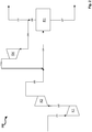
- Figure 1 shows a greatly simplified schematic block flow diagram of a production process for methanol with a recycle gas compressor stage in a synthesis cycle with a single reactor stage and a single compressor stage for fresh gas.
- a first fresh gas stream 101 at a pressure of 34 bar is fed to a first compressor stage K1.
- the fresh gas of the fresh gas stream 101 comes from a feed gas source which provides a feed gas that contains only carbon dioxide with regard to carbon oxides. Due to the molar ratio of carbon dioxide to hydrogen of 3 to 1, a stoichiometric number SN of 2.0 results for the fresh gas of the fresh gas flow 101.
- the fresh gas flow 101 is compressed by the first compressor stage K1, so that a second fresh gas flow 102 results on the pressure side of the compressor stage K1.
- the second fresh gas stream 102 is combined with the recirculation gas stream 104b, which results in a combined gas stream which is referred to here as synthesis gas stream 103.
- the compression by compressor stage K1 has the effect that synthesis gas stream 102 has a pressure of 85.0 bar at the inlet of reactor stage R1.
- Synthesis gas from synthesis gas stream 102 is converted in reactor stage R1 over a copper-based fixed bed catalyst with a catalyst volume of 16.8 m 3 to form methanol.
- the pressure at the reactor outlet of the reactor of R1 is 81.2 bar.
- the conversion is incomplete, as a result of which a stream of unreacted synthesis gas 105 is obtained, which is partially fed as recycle gas stream 104a to recycle gas compressor stage RK and compressed so that recycle gas stream 104b is obtained on the pressure side of recycle gas compressor stage RK.
- reactor stage R1 also has a heat exchanger for cooling the product stream and a separator. By cooling the product stream and condensing methanol in the separator, a product stream 106 comprising methanol is obtained.
- the methanol is in the form of crude methanol and is fed to a suitable work-up depending on the required purity to obtain pure methanol (not shown).
- the carbon dioxide conversion is in the comparative example Figure 1 98.5% and the hydrogen conversion is 98.8%.
- the amount of recirculation gas to be compressed by the recirculation gas compressor stage thus corresponds to three and a half times the amount of fresh gas, in each case based on the standard volume flows of recirculation gas and fresh gas.
- Figure 2 shows a greatly simplified schematic block flow diagram of a production process for methanol with a recycle gas compressor stage in a synthesis cycle with a reactor stage and two series-connected compressor stages for fresh gas.
- the procedure of Figure 2 differs from the procedure of Figure 1 thus exclusively in the use of an additional compressor stage for fresh gas.
- a first fresh gas stream 201 at a pressure of 34 bar is fed to a first compressor stage K1.
- the fresh gas of the fresh gas stream 201 comes from a feed gas source which provides a feed gas that contains only carbon dioxide with regard to carbon oxides. Due to the molar ratio of carbon dioxide to hydrogen of 3 to 1, a stoichiometric number SN of 2.0 results for the fresh gas of the fresh gas flow 101.
- the fresh gas stream 201 is compressed by the first compressor stage K1, so that a second fresh gas stream 202 with a pressure of 65.0 bar results on the pressure side of the compressor stage K1.
- the second fresh gas flow 202 is compressed by the second compressor stage K2, a third fresh gas flow 203 resulting on the pressure side of K2.
- the third fresh gas stream 203 is combined with the recirculation gas stream 206b, which results in a combined gas stream, which here is the synthesis gas stream 204 referred to as.
- the compression by compressor stage K2 has the effect that synthesis gas stream 204 has a pressure of 85.0 bar at the inlet of reactor stage R1.
- Synthesis gas from synthesis gas stream 204 is converted in reactor stage R1 over a copper-based fixed bed catalyst with a catalyst volume of 16.8 m 3 to form methanol.
- the pressure at the reactor outlet is 81.2 bar.
- reactor stage R1 also has a heat exchanger for cooling the product stream and a separator. By cooling the product stream and condensing methanol in the separator, a product stream 207 comprising methanol is obtained.
- the methanol is in the form of raw methanol and, depending on the required purity, is fed to a suitable work-up to obtain pure methanol (not shown).
- the carbon dioxide conversion is in the comparative example Figure 2 likewise 98.5% and the hydrogen conversion is likewise 98.8%.
- t / d crude methanol per day
- a compressor output of 1090 kW for K1 and K2 together and 325 kW for RK are required, which corresponds to a total compressor output of 1415 kW.
- the total compressor output is thus somewhat lower than in the comparative example of Figure 1 , however, three compressor stages K1, K2 and RK are required, which increases the CAPEX of the system.
- Figure 3 shows a greatly simplified schematic block flow diagram of a production process according to the invention for methanol without a recycle gas compressor stage Synthesis circuit, the synthesis circuit comprising a plurality of reactor stages arranged in series.
- a first fresh gas stream 301 at a pressure of 34.0 bar is fed to a first compressor stage K1.
- the fresh gas of the fresh gas stream 301 comes from a feed gas source which, with regard to carbon oxides, provides feed gas containing only carbon dioxide. Due to the molar ratio of carbon dioxide to hydrogen of 3 to 1, a stoichiometric number SN of 2.0 results for the fresh gas of the fresh gas stream 301.
- the first fresh gas stream 301 is compressed by the first compressor stage K1, so that a second fresh gas stream 302 with a pressure of 65.0 bar is obtained on the pressure side of the compressor stage K1.
- the second fresh gas flow 302 is combined with recirculation gas flow 305, resulting in a combined gas flow 303 which is introduced into a second compressor stage K2 and is compressed to a pressure of 85.0 bar.
- a gas flow with synthesis pressure which is referred to here as synthesis gas flow 304, results on the pressure side of the second compressor stage.
- the synthesis gas stream 304 is introduced into a first of a total of four reactor stages R1 to R4 arranged in series.
- synthesis gas 304 is converted to methanol over a copper-based fixed bed catalyst with a catalyst volume of 4.2 m 3.
- the reactor stages R2, R3 and R4 each have a catalyst volume of 4.2 m 3 of the same copper-based catalyst, so that a total catalyst volume of 16.8 m 3 results, which is the catalyst volume of the individual reactor stage in the comparative examples Figure 1 and Figure 2 corresponds.
- a stream of unreacted synthesis gas 306a is obtained, which is introduced into the following reactor stages arranged in series, here in reactor stage R2.
- Reactor stage R1 and further reactor stages R2 to R4 have, in addition to the actual reactor, also a heat exchanger for cooling the product stream and a separator. By cooling the product stream and condensing methanol in the separator, a product stream 307a is obtained in R1.
- unreacted synthesis gas 306a is converted into methanol and by-products in reactor stage R2, whereby a further product stream 307b is obtained.
- Synthesis gas not reacted in the reaction on the copper-based catalyst of R2 is again introduced into the following reactor stage R3, a product stream 307c and unreacted synthesis gas 306c being obtained.
- a small proportion of unreacted synthesis gas R2 is always dissolved in the condensate (methanol) and is not available for the next reactor stage.
- Unreacted synthesis gas 306c is introduced into the last of the reactor stages R4 arranged in series, a further product stream 307d being obtained.
- the product streams 307a to 307d are combined to form a total product stream 307.
- Total product stream 307 has crude methanol which, depending on the required purity, is fed to a suitable work-up for obtaining pure methanol (not shown).
- the pressure at the reactor outlet of reactor stage R4 is 74.9 bar.
- the pressure loss over all reactor stages is thus 10.1 bar.
- Synthesis gas 306d which has not reacted in the last reactor stage is returned directly as recycle gas stream 305 to the second fresh gas stream 302 and is combined with it.
- a part of the unreacted synthesis gas withdrawn in the last reactor stage R4 is used in the example according to Figure 3 branched off as a purge gas stream in order to avoid the accumulation of inert components and by-products in the recycle gas stream 305.
- the carbon dioxide conversion is in the example Figure 3 98.3% and the hydrogen conversion is 98.6%.
- the sales are thus with the sales according to the comparative examples (setup of Figures 1 and 2 ) comparable.
- the recirculation gas amount 305 thus corresponds to 90% of the fresh gas amount 302, in each case based on the standard volume flows of recirculation gas and fresh gas.
- the recirculation rate is therefore lower by a factor of about 3.9 with the same carbon and hydrogen conversion than in the comparative examples, which is due to the higher conversion and the intermediate condensation of products in the majority of the reactor stages (R1 to R4).
- the recirculation rate Due to the substoichiometric fresh gas (H 2 in deficit and carbon dioxide in excess), the recirculation rate surprisingly drops to 0.41, i.e. less than half of the recirculation gas 305 in relation to the fresh gas 302 is required to produce the same amount of raw methanol 307 of 344 tons per day (of which 217.5 t / d methanol, the remainder essentially water) with simultaneously high hydrogen conversion.
- the lower recycle gas amount 305 also leads to a lower amount of purge gas required, which in turn means savings in hydrogen recovery.
- the hydrogen conversion is 98.8% and is therefore comparable with all previous examples.
- the carbon conversion is slightly lower at 89.5%, but this has no impact on the overall economy of the process in view of the low costs of this raw material, especially if it comes from exhaust gas sources.
Landscapes
- Chemical & Material Sciences (AREA)
- Organic Chemistry (AREA)
- Chemical Kinetics & Catalysis (AREA)
- Organic Low-Molecular-Weight Compounds And Preparation Thereof (AREA)
Abstract
Description
- Die Erfindung betrifft ein Verfahren zur Herstellung von Methanol, eine Anlage zur Herstellung von Methanol sowie die Verwendung der erfindungsgemäßen Anlage in einem erfindungsgemäßen Verfahren.
- Methanol wird heute üblicherweise aus Synthesegas, einem Gemisch aus vorwiegend Wasserstoff (H2), Kohlenmonoxid (CO) sowie Kohlendioxid (CO2) im sogenannten Niederdruckverfahren bei Drücken zwischen 60 und 120 bar hergestellt. Je nach Technologie und Anlagenkapazität kommen bezogen auf die Reaktorsektion des Verfahrens entweder einstufige oder zweistufige Verfahren zur Anwendung, um das Synthesegas mit hoher Ausbeute zu Methanol umzusetzen.
- Bei den verwendeten Verfahren wird das Synthesegas, welches meist bei Drücken zwischen 20 und 40 bar erzeugt wird, zunächst über einen Gaskompressor (Synthesegaskompressor) auf den für die Reaktion erforderlichen Druck von größer als 60 bar gebracht. Die Verfahren arbeiten ferner meist mit hohen Gaskreisläufen in einem sogenannten Synthesekreislauf, auch als Syntheseloop bezeichnet, in dem nicht im ersten Reaktordurchgang (per-pass) zu Methanol umgesetztes Synthesegas als Rückführgas, auch als Recyclegas bezeichnet, zum Reaktoreingang zurückgeführt wird. Der Synthesekreislauf ist erforderlich, um trotz der niedrigen per-pass Umsätze ausreichend hohe Synthesegasumsätze und damit Gesamtausbeuten zu erzielen.
- Die Rückführgasmenge liegt dabei je nach Technologie, Frischgaszusammensetzung und Reaktorsystem bis zu 5 mal höher als die zugeführte Frischgasmenge aus der Synthesegaserzeugung. Dies ist vor allem bei Synthesegas- bzw. Frischgaszusammensetzungen mit hohem CO2-Gehalt der Fall, bei denen im Vergleich zu eher CO-reichen Synthesegasen ein deutlich niedrigerer thermodynamischer Gleichgewichtsumsatz vorliegt. Zur Förderung und Verdichtung der hohen Gaskreislaufmengen kommt üblicherweise ein dedizierter Kreislaufgaskompressor zum Einsatz.
- Ein Nachteil dieser hohen Rezirkulationsraten ist die Akkumulation von inerten, das heißt unter den Bedingungen der Methanolsynthese nicht umsetzbaren Bestandteilen wie Methan und Stickstoff, welche als Spülgas, auch als Purgegas bezeichnet, aus dem Synthesekreislauf zu entfernen sind. Dabei wird üblicherweise auch Wasserstoff mitentfernt, welcher anschließend aufwändig zurückgewonnen werden muss, was meist mit Hilfe einer Wechseldruckabsorptionsvorrichtung geschieht.
- Beispiele für Verfahren mit Synthesekreislauf sind in der
WO 2015/193440 A1 , derWO 2017/167642 A1 sowie derEP 2 116 295 A1 offenbart. - Durch das Hinzufügen von zusätzlichen Reaktorstufen inklusive Zwischenkondensation des je Reaktorstufe erzeugten Methanols kann der per-pass Umsatz über die Gesamtzahl der Reaktorstufen erhöht werden und dadurch die Rezirkulationsrate verringert werden.
- Bei der Verwendung eines Synthesekreislaufs, welcher große Mengen nicht reagierten Synthesegases fördert, müssen die einzelnen Komponenten der betreffenden Produktionsanlage für die großen Rückführgasflüsse entsprechend groß dimensioniert werden. Dies hat zur Folge, dass die gesamten Investitionskosten (CAPEX) der Anlage ansteigen und/oder bei hohen erforderlichen Kapazitäten die Abmessungen der Reaktoren, insbesondere der äußere Durchmesser, an die Transportlimitierungen des jeweiligen Anlagenprojekts kommen können. Zusätzlich wird für die Rückverdichtung des Rückführgases auf Reaktionsdruck eine zusätzliche KompressorEinheit (Rückführgas- oder Recyclegas-Kompressor) benötigt, womit nicht nur die Investitionskosten (CAPEX) erhöht werden, sondern auch die gesamte erforderliche Kompressorleistung und damit die Betriebskosten der Anlage (OPEX).
- Ein hoher Anteil von CO2 und unter den Bedingungen der Methanolsynthese inerter Bestandteile wie Methan (CH4) und Stickstoff (N2) verstärken diesen negativen Effekt zusätzlich. Durch die Verwendung mehrerer hintereinandergeschalteter Reaktorstufen inklusive Zwischenkondensation kann zwar der Anteil des Rückführgases (Recycle-Gases) verringert werden, es erhöht sich jedoch gleichzeitig die Anzahl der erforderlichen Prozesseinheiten, wodurch die Investitionskosten (CAPEX) üblicherweise auch steigen. Wird auf einen Synthesekreislauf vollständig verzichtet ("oncethrough"-Prozess), so erhöht sich die Anzahl der erforderlichen Reaktoren weiter, so dass der Verzicht auf den Synthesekreislauf wiederum negativ kompensiert wird.
- Im Zuge der Diskussion über den vom Menschen verursachten Klimawandel sind Synthesegase mit hohem CO2-Gehalt verstärkt in den Fokus gerückt. So wird beispielsweise in Erwägung gezogen, hochkohlendioxidhaltige Abgase für die Erzeugung von Synthesegasen zu nutzen, anstatt diese Abgase beispielsweise zu sequestrieren. So ist beispielsweise die Erzeugung von Synthesegasen aus Kohlendioxid aus Abgasquellen durch Kombination mit Wasserstoff aus einer Wasserelektrolyse denkbar, wobei der Strom für die Wasserelektrolyse aus regenerierbaren Energiequellen stammen könnte. Ein solches Synthesegas ist als klimaneutral zu betrachten, enthält jedoch nur sehr wenig bis gar kein Kohlenmonoxid.
- Wie oben erwähnt führen hohe Kohlendioxidanteile im Synthesegas zu hohen Rezirkulationsraten in Bezug auf den Synthesekreislauf, was CAPEX und OPEX der Anlage erhöht. Eine Kompensation durch Einführung mehrerer Reaktionsstufen ist nur teilweise möglich, weil auch diese Vorgehensweise den CAPEX erhöht.
- Bei der Synthese von Methanol aus Kohlendioxid und Wasserstoff fällt weiterhin Wasser gemäß der Reaktionsgleichung
CO2 + 3 H2 ⇄ CH3OH + H2O
an, was bei der Umsetzung von Kohlenmonoxid mit Wasserstoff zu Methanol gemäß der Reaktionsgleichung
CO + 2 H2 ⇄ CH3OH
nicht der Fall ist. - Die Akkumulation von Wasser im Reaktor führt gerade bei der Verwendung von hohen Rezirkulationsraten zu einer sukzessiven Deaktivierung des bei der Methanolsynthese verwendeten, meist Kupfer-basierten, Katalysators. Durch Verwendung mehrerer in Serie geschalteter Reaktorstufen mit Zwischenkondensation von Methanol und Wasser kann dieser Effekt durch Senkung des Wasser-Partialdrucks im Katalysatorbett verringert werden. Jedoch, wie bereits oben erwähnt, steigen durch die Verwendung mehrerer Reaktor-Stufen die Investitionskosten der betreffenden Anlage.
- Für Synthesegase mit ausschließlich oder hauptsächlich Kohlendioxid als reaktiver Kohlenstoff-Komponente und Wasserstoff wird üblicherweise ein stöchiometrisches oder leicht überstöchiometrisches Verhältnis beim Frischgas angesetzt. Die Stöchiometriezahl SN, definiert als

- Im Hinblick auf die Herstellung von Methanol aus Synthesegasen mit hohem Kohlendioxid-Anteil besteht somit Bedarf für die Verbesserung bestehender Verfahren.
- Eine Aufgabe der vorliegenden Erfindung besteht darin ein Verfahren zur Herstellung von Methanol bereitzustellen, welches die Nachteile des Standes der Technik zumindest teilweise überwindet.
- Eine weitere Aufgabe der vorliegenden Erfindung besteht darin ein Verfahren zur Herstellung von Methanol bereitzustellen, welches Einsparungen bezüglich der für das Verfahren aufzuwendenden Energie, insbesondere zum Betrieb von Gaskompressoren, ermöglicht.
- Eine weitere Aufgabe der vorliegenden Erfindung besteht darin ein Verfahren zur Herstellung von Methanol bereitzustellen, welches Einsparungen bezüglich der für das Verfahren bereitzustellenden Anlagenteile, insbesondere im Hinblick auf die Zahl erforderlicher Kompressorstufen, ermöglicht.
- Eine weitere Aufgabe der vorliegenden Erfindung besteht darin ein Verfahren zur Herstellung von Methanol bereitzustellen, welches Wasserstoff-Verluste über einen Purgegas-Strom (Spülgas-Strom) weitestgehend vermeidet.
- Eine weitere Aufgabe der vorliegenden Erfindung besteht darin ein Verfahren zur Herstellung von Methanol bereitzustellen, welches die Katalysator-Belastung durch einen hohen Wasser-Partialdruck im Katalysatorbett verringert und die Lebensdauer der verwendeten Katalysatoren verlängert.
- Eine weitere Aufgabe der vorliegenden Erfindung besteht darin ein Verfahren zur Herstellung von Methanol bereitzustellen, welches die Menge an in einem Synthesekreislauf rückzuführenden Synthesegas so weit wie möglich verringert.
- Eine weitere Aufgabe der vorliegenden Erfindung besteht darin eine Anlage zur Herstellung von Methanol bereitzustellen, welche zumindest eine der vorgenannten Aufgaben zumindest teilweise löst.
- Ein Beitrag zur mindestens teilweisen Erfüllung mindestens einer der obigen Aufgaben wird durch die unabhängigen Ansprüche geleistet. Die abhängigen Ansprüche stellen bevorzugte Ausführungsformen bereit, die zur mindestens teilweisen Erfüllung mindestens einer der Aufgaben beitragen. Bevorzugte Ausgestaltungen von Bestandteilen einer erfindungsgemäßen Kategorie sind, soweit zutreffend, ebenso bevorzugt für gleichnamige oder entsprechende Bestandteile einer jeweils anderen erfindungsgemäßen Kategorie.
- Die Ausdrücke "aufweisend", "umfassend" oder "beinhaltend" etc. schließen nicht aus, dass weitere Elemente, Inhaltsstoffe etc. enthalten sein können. Der unbestimmte Artikel "ein" schließt nicht aus, dass eine Mehrzahl vorhanden sein kann.
- Die vorgenannten Aufgaben werden zumindest teilweise gelöst durch ein Verfahren zur Herstellung von Methanol, umfassend folgende Prozessschritte, wobei diese nicht zwingend in der angegebenen Reihenfolge auszuführen sind:
- a) Bereitstellen eines Kohlenstoffoxide und Wasserstoff (H2) aufweisenden Einsatzgases, wobei der Anteil an Kohlendioxid (CO2) im Einsatzgas, in Bezug auf die Gesamtmenge der Kohlenstoffoxide, wenigstens 80 Vol.-% beträgt;
- b) Einschleusen des Einsatzgases als einen ersten Frischgasstrom in eine erste Kompressorstufe zur Vorverdichtung des ersten Frischgasstroms, wobei ein zweiter Frischgasstrom erhalten wird;
- c) Einschleusen eines Rückführgasstroms und des zweiten Frischgasstroms in eine zweite Kompressorstufe zur Verdichtung des Rückführgasstroms und des zweiten Frischgasstroms auf Synthesedruck, wobei ein Synthesegasstrom erhalten wird;
- d) Katalytisches Umsetzen des Synthesegases des Synthesegasstroms in einer Mehrzahl in Serie angeordneter Reaktorstufen bei Synthesedruck, wobei je Reaktorstufe ein Methanol und nicht reagiertes Synthesegas aufweisender Produktstrom erhalten wird;
- e) Kühlung des je Reaktorstufe erhaltenen Produktstroms zur Kondensation und Abtrennung von Methanol von nicht reagiertem Synthesegas und Einschleusen von nicht reagiertem Synthesegases in eine jeweils folgende der in Serie angeordneten Reaktorstufen;
- f) Abziehen von nicht reagiertem Synthesegas aus zumindest einer der Reaktorstufen als Rückführgasstrom zum Einschleusen des Rückführgasstroms in die zweite Kompressorstufe gemäß Schritt c).
- Erfindungsgemäß wird das Rückführgas zusammen mit dem vorverdichteten zweiten Frischgasstrom in die zweite Kompressorstufe eingeschleust. Durch die katalytische Umsetzung des Synthesegases in einer Mehrzahl in Serie angeordneter Reaktorstufen wird die Rückführgasmenge reduziert. Dadurch kann aus einer oder mehreren Reaktorstufen abgezogener Rückführgasstrom unmittelbar der zweiten Kompressorstufe (zusammen mit dem zweiten Frischgasstrom) zugeführt werden, wodurch die für das Verfahren gesamte erforderliche Kompressorleistung überraschenderweise sinkt.
- Je Reaktorstufe wird Synthesegas zu einem Produktstrom umgesetzt, welcher Methanol aufweist. Dabei handelt es sich um ein Rohmethanol, welches außer Methanol als Solchem auch Wasser und weitere kondensierbare Nebenprodukt enthalten kann. Der Wassergehalt des Rohmethanols steigt dabei mit der Konzentration von Kohlendioxid im Einsatzgas.
- Methanol wird durch Kühlung und dadurch erfolgende Kondensation vom verbleibenden Synthesegasstrom abgetrennt, womit überwiegend nicht reagiertes Synthesegas in der Gasphase verbleibt. Dieses wird in die jeweils folgende der in Serie angeordneten Reaktorstufen eingeschleust. Wie für den Fachmann offensichtlich bildet dabei die letzte der in Serie angeordneten Reaktorstufen eine Ausnahme. Aus der letzten der in Serie angeordneten Reaktorstufen abgezogenes nicht reagiertes Synthesegas wird als Rückführgasstrom in die zweite Kompressorstufe eingeschleust. Optional wird ein bestimmter Anteil des Rückführgasstroms als Purge-Gasstrom vom Rückführgasstrom abgetrennt. Nicht reagiertes Synthesegas wird in diesem Fall zumindest teilweise aus zumindest einer der Reaktorstufen als Rückführgasstrom zum Einschleusen des Rückführgasstroms in die zweite Kompressorstufe gemäß Schritt c) abgezogen.
- Gemäß Schritt e) wird Methanol durch Kühlung und Kondensation aus dem erhaltenen Produktstrom zumindest teilweise von nicht reagiertem Synthesegas abgetrennt. Dabei wird eine vollständige Abtrennung von Methanol durch Kühlung und Kondensation von nicht reagiertem Synthesegas angestrebt, um das Reaktionsgleichgewicht auf die Seite des Produkts (Methanol) zu verschieben.
- Eine bevorzugte Ausführungsform des erfindungsgemäßen Verfahrens ist dadurch gekennzeichnet, dass der Rückführgasstrom nach dem Abziehen gemäß Schritt f) ohne vorhergehende Verdichtung in die zweite Kompressorstufe eingeschleust wird.
- Vorzugsweise wird der Rückführgasstrom unmittelbar und ohne den Einsatz eines Rückführgas-Kompressors (Recyclegas-Kompressor), das heißt ohne den Einsatz einer weiteren Kompressorstufe zur Verdichtung des Rückführgases, der zweiten Kompressorstufe zugeführt. Dadurch sinkt nicht nur die gesamte erforderliche Kompressorleistung des Verfahrens (Rückgang des OPEX). Es kann zusätzlich auch auf die Anschaffung eines Rückführgas-Kompressors verzichtet werden, wodurch auch die Investitionskosten (CAPEX) für das Verfahren sinken. Für die gesamte Methanolsynthese sind in diesem Fall lediglich zwei Kompressorstufen erforderlich, nämlich die erste Kompressorstufe zur Verdichtung des ersten Frischgases zur Erzeugung des zweiten Frischgases, sowie die zweite Kompressorstufe zur Verdichtung des zweiten Frischgases zusammen mit dem Rückführgas auf Synthesedruck, zur Erzeugung des Synthesegases.
- Eine bevorzugte Ausführungsform des erfindungsgemäßen Verfahrens ist dadurch gekennzeichnet, dass gemäß Schritt e) nicht reagiertes Synthesegas vollständig in die jeweils folgende der in Serie angeordneten Reaktorstufen eingeschleust wird. Dabei wird die maximal mögliche Menge an nicht reagiertem Synthesegas in die jeweils folgende der in Serie angeordneten Reaktorstufen eingeschleust, was hier unter "vollständig" zu verstehen ist. Wie dem Fachmann in diesem Fall bekannt, wird stets ein kleiner Teil des nicht reagierten Synthesegases im Kondensat (Methanol) gelöst. Dieser kleine Teil kann dementsprechend nicht in die folgende Reaktorstufe eingeschleust werden.
- Gemäß dieser Ausführungsform fällt nicht reagiertes Synthesegas nur in der letzten der in Serie angeordneten Reaktorstufen an und die Menge des Rückführgasstroms wird auf ein Minimum reduziert.
- Eine bevorzugte Ausführungsform des erfindungsgemäßen Verfahrens ist somit ferner dadurch gekennzeichnet, dass gemäß Schritt f) nicht reagiertes Synthesegas aus der letzten der Mehrzahl in Serie angeordneten Reaktorstufen als Rückführgasstrom abgezogen wird, insbesondere ausschließlich aus der letzten der Mehrzahl in Serie angeordneten Reaktorstufen abgezogen wird.
- Eine bevorzugte Ausführungsform des erfindungsgemäßen Verfahrens ist dadurch gekennzeichnet, dass der Rückführgasstrom und der zweite Frischgasstrom zusammengeführt und als kombinierter Gasstrom in die zweite Kompressorstufe eingeschleust werden.
- Beide Ströme werden in diesem Fall nach der Zusammenführung zunächst gemischt und anschließend als kombinierter Gasstrom in die zweite Kompressorstufe eingeschleust.
- Eine bevorzugte Ausführungsform des erfindungsgemäßen Verfahrens ist dadurch gekennzeichnet, dass das Einsatzgas eine Stöchiometriezahl SN, wobei gilt

- Das erfindungsgemäße Verfahren eignet sich insbesondere für stark unterstöchiometrische hochkohlendioxidhaltige Synthesegase bis leicht überstöchiometrische hochkohlendioxidhaltige Einsatzgase.
- Dabei wird bevorzugt, dass das Einsatzgas eine Stöchiometriezahl SN von 1,5 bis 1,9 aufweist, vorzugsweise von 1,6 bis 1,8 aufweist.
- Überraschenderweise haben Untersuchungen gezeigt, dass Zusammensetzungen gemäß vorgenannter Stöchiometriezahl eine weitere Reduzierung der gesamten erforderlichen Kompressorleistung des erfindungsgemäßen Verfahrens ermöglichen. Liegt die Stöchiometriezahl niedriger als 2, und weist das Einsatzgas in Bezug auf die Kohlenstoffoxide beispielsweise ausschließlich Kohlendioxid auf, so ist das Verhältnis von Wasserstoff zu Kohlendioxid kleiner als das (ideale) stöchiometrische Verhältnis von 3 zu 1. Kohlendioxid liegt somit im Überschuss vor. Dadurch wird der Wasserstoff-Umsatz verbessert, was sich zusätzlich positiv auf die Gesamtökonomie des Verfahrens auswirkt. Denn es ist davon auszugehen, dass Wasserstoff im Vergleich zu Kohlendioxid stets der teurere Rohstoff ist, wodurch Wasserstoff die Wirtschaftlichkeit des Verfahrens entscheidend beeinflusst.
- Eine bevorzugte Ausführungsform des erfindungsgemäßen Verfahrens ist dadurch gekennzeichnet, dass für eine Rezirkulationsrate R, definiert als

- Dabei werden unter den Volumenströmen jeweils die genormten Volumenströme, bezogen auf den physikalischen Normzustand des jeweiligen Gases bei 0 °C und 1,01325 bar Absolutdruck (Normvolumenstrom), verstanden.
- Im Vergleich zu bekannten Verfahren sind die Rezirkulationsraten gemäß erfindungsgemäßem Verfahren durch die Verwendung einer Mehrzahl in Serie angeordneter Reaktionsstufen mit Zwischenkondensation sehr niedrig.
- Dabei ist weiter bevorzugt, dass für die Rezirkulationsrate R gilt: 0,1 ≤ R ≤ 0,5.
- Insbesondere bei der Verwendung unterstöchiometrischer Einsatzgase, also Einsatzgasen mit einer Stöchiometriezahl von kleiner als 2, kann die Rezirkulationsrate bei konstant hohem Wasserstoffumsatz weiter reduziert werden, wie Untersuchungen überraschenderweise gezeigt haben. Wird die Menge des Rückführgasstroms weiter reduziert, insbesondere auf Werte deutlich kleiner als 1, sinkt entsprechend auch die gesamte erforderliche Kompressorleistung.
- Eine bevorzugte Ausführungsform des erfindungsgemäßen Verfahrens ist dadurch gekennzeichnet, dass über die Gesamtheit der Mehrzahl der in Serie angeordneten Reaktorstufen, ausgehend vom Einsatzgas, ein Kohlendioxid-Umsatz von wenigstens 80 mol-% erzielt wird.
- Ausgehend vom Einsatzgas liegt der Anteil des über alle Reaktorstufen umgesetzten Kohlendioxids, unter Berücksichtigung des Rückführgasstroms und somit als Gesamtbilanz betrachtet, vorzugsweise bei mindestens 80 mol-%. Besonders bevorzugt liegt der Kohlendioxid-Umsatz bei mindestens 90 mol-%, weiter bevorzugt bei wenigstens 95 mol-% und weiter bevorzugt bei mindestens 98 mol-%.
- Da Kohlendioxid in den meisten Fällen ein billiger Rohstoff ist, sind Umsätze von zumindest 80 mol-% ökonomisch akzeptabel und damit bevorzugt, wobei höhere Umsätze weiter bevorzugt sind, da sich dann umso weniger die Frage bezüglich der Verwertung von nicht umgesetztem Kohlendioxid stellt.
- Vorzugsweise liegt der Wasserstoff-Umsatz bei mindestens 95 mol-%, weiter bevorzugt bei mindestens 98 mol-% oder mindestens 99 mol-%. Vorzugsweise ist ein möglichst hoher Wasserstoff-Umsatz zu erzielen, da in vielen Fällen Wasserstoff im Gegensatz zu Kohlendioxid die wesentlich teurere Rohstoffquelle darstellt.
- Eine bevorzugte Ausführungsform des erfindungsgemäßen Verfahrens ist dadurch gekennzeichnet, dass die Mehrzahl der in Serie angeordneten Reaktorstufen eine Anzahl von 2 bis 8 Reaktorstufen umfasst.
- Die optimale Anzahl der Reaktorstufen hängt von einer Vielzahl von Faktoren wie der zu produzierenden Methanol-Menge, des Umsatzes pro Reaktorstufen, Zusammensetzung des Einsatzgases sowie gegebenenfalls weiterer Faktoren ab. Allgemein steigen die Investitionskosten mit der Anzahl der Reaktorstufen an und die Menge des Rückführgasstroms nimmt ab, wodurch Einsparungen bezüglich der Kompressorleistung besonders hoch sind. Umgekehrt sinken die Investitionskosten mit der Verringerung der Anzahl an Reaktionsstufen, jedoch steigt die Menge des Rückführgasstrom an, wodurch die Einsparungen bezüglich der Kompressorleistung geringer ausfallen.
- Vorzugsweise umfasst die Mehrzahl der in Serie angeordneten Reaktorstufen daher eine Anzahl von 3 bis 5 Reaktorstufen, besonders bevorzugt eine Anzahl von 4 Reaktorstufen. Dadurch wird ein optimaler Kompromiss im Hinblick auf Investitionskosten und Einsparung von Kompressorleistung erzielt.
- Die Aufgaben der Erfindung werden ferner zumindest teilweise gelöst durch eine Anlage für die Herstellung von Methanol, aufweisend folgende miteinander in Fluidverbindung stehende Anlagenelemente:
- Eine erste Kompressorstufe zum Vorverdichten eines Kohlenstoffoxide und Wasserstoff (H2) aufweisenden ersten Frischgases zur Erzeugung eines zweiten Frischgases;
- eine stromabwärts zur ersten Kompressorstufe angeordnete zweite Kompressorstufe zur Verdichtung des zweiten Frischgases und eines Rückführgases zu einem Synthesegas bei Synthesedruck;
- eine stromabwärts zur zweiten Kompressorstufe angeordnete Mehrzahl in Serie angeordneter Reaktoreinheiten zur Erzeugung eines Methanol und nicht reagiertes Synthesegas aufweisenden Produktstroms aus Synthesegas, wobei jede der Reaktoreinheiten
- einen ein Katalysatorbett aufweisenden Reaktor,
- einen Wärmeaustauscher zur Kühlung des Produktstroms, sowie
- einen Abscheider zur Abtrennung von Methanol von nicht reagiertem Synthesegas
- Der erfindungsgemäßen Anlage ist eine Produktionseinheit zur Erzeugung eines Wasserstoff (H2) und Kohlenstoffoxide aufweisenden Einsatzgases vorgeschaltet. Das Einsatzgas weist in Bezug auf die Gesamtmenge der Kohlenstoffoxide einen Anteil von wenigstens 80 Vol.-% Kohlendioxid (CO2) auf. Das Einsatzgas wird der erfindungsgemäßen Anlage als erstes Frischgas zugeführt.
- Eine bevorzugte Ausführungsform der erfindungsgemäßen Anlage ist dadurch gekennzeichnet, dass zwischen dem Auslass zum Zuführen von nicht reagiertem Synthesegas als Rückführgas zur zweiten Kompressorstufe und der Zuführung zum Einschleusen des Rückführgases in die zweite Kompressorstufe keine Kompressorstufe zur vorherigen Verdichtung des Rückführgases vor dem Einschleusen in die zweite Kompressorstufe angeordnet ist.
- Vorzugsweise wird das nicht reagierte Synthesegas nach Abziehen aus einer Reaktoreinheit als Rückführgas unmittelbar der zweiten Kompressorstufe zugeführt. In diesem Fall ist zwischen dem Auslass der Reaktoreinheit und der Zuführung zur zweiten Kompressoreinheit keine zusätzliche Kompressorstufe zur Verdichtung des Rückführgases vor dem Zuführen zur zweiten Kompressorstufe vorgesehen.
- Eine bevorzugte Ausführungsform der erfindungsgemäßen Anlage ist dadurch gekennzeichnet, dass ein Auslass zum Zuführen von nicht reagiertem Synthesegas als Rückführgas zur zweiten Kompressorstufe an der letzten der Mehrzahl in Serie angeordneten Reaktoreinheiten angeordnet ist, vorzugsweise ausschließlich an der letzten der Mehrzahl in Serie angeordneten Reaktoreinheiten angeordnet ist.
- Vorzugsweise weisen alle Reaktoreinheiten, mit Ausnahme der letzten der in Serie angeordneten Reaktoreinheiten, einen Auslass zum Zuführen von nicht reagiertem Synthesegas einer Reaktoreinheit zu einer jeweils nachfolgend angeordneten Reaktoreinheit auf. Nur die letzte der in Serie angeordneten Reaktoreinheiten weist einen Auslass zum Zuführen von nicht reagiertem Synthesegas einer Reaktoreinheit als Rückführgas zur zweiten Kompressorstufe auf. Dadurch wird die Menge des Rückführgases auf ein Minimum reduziert.
- Die Aufgaben der Erfindung werden ferner zumindest teilweise gelöst durch die Verwendung der erfindungsgemäßen Anlage in einem Verfahren gemäß der Erfindung.
- Das Einsatzgas weist zumindest Wasserstoff (H2) und Kohlenstoffoxide auf. Unter dem Begriff "Kohlenstoffoxide" werden die Verbindungen Kohlenmonoxid (CO) sowie Kohlendioxid (CO2) subsummiert. In Bezug auf die Gesamtmenge der Kohlenstoffoxide weist das Einsatzgas einen Kohlendioxid-Anteil von wenigstens 80 Vol.-% auf. Das Einsatzgas ist somit hochkohlendioxidhaltig. In einem Beispiel weist das Einsatzgas in Bezug auf die Kohlenstoffoxide wenigstens 90 Vol.-% Kohlendioxid auf, oder zumindest 95 Vol.-%, oder zumindest 98 Vol.-%, oder zumindest 99 Vol.-%. In einem Beispiel weist das Einsatzgas in Bezug auf die Kohlenstoffoxide ausschließlich Kohlendioxid auf. Ein solches Einsatzgases weist kein Kohlenmonoxid auf, oder es weist Kohlenmonoxid nur in Spuren auf.
- Das Einsatzgas kann aus jeder dem Fachmann bekannten Quelle stammen. Vorzugsweise stammt das Kohlendioxid des Einsatzgases aus einer Abgasquelle. Vorzugsweise stammt der Wasserstoff des Einsatzgases aus einer Wasserelektrolyse-Anlage, wobei der elektrische Strom für diese Anlage vorzugsweise durch eine regenerative Energiequelle wie Wasserkraft, Windkraft oder Photovoltaik erzeugt wurde. In einem weiteren Beispiel stammt das Einsatzgas aus einem Reformierungsverfahren. Dabei wird das Wasserstoff und Kohlenstoffoxide aufweisende Einsatzgas durch Reformierung eines Kohlenwasserstoffe aufweisenden Rohmaterials wie Methan oder Erdgas erzeugt. Der Reformierungsprozess kann einen oder mehrere Schritte wie Dampfreformierung, partielle Oxidation oder autotherme Reformierung aufweisen. Vorzugsweise wurde das Reformierungsprodukt in einer Wassergas-Shift-Reaktion weiter umgesetzt. Dabei werden Kohlenmonoxid und Wasser zu Kohlendioxid und Wasserstoff umgesetzt werden und dadurch das hochkohlendioxidhaltige Einsatzgas erhalten.
- Das Einsatzgas kann, unabhängig von der Quelle aus der es stammt, bei einer Temperatur zwischen 400 °C und 1200 °C und/oder bei einem Druck zwischen 10 und 60 bar erzeugt werden. Das Einsatzgas kann außer den vorgenannten Bestandteilen auch unterschiedliche Mengen inerter Bestandteile wie Methan oder Stickstoff enthalten. Unter inerten Bestanteilen sind dabei insbesondere unter den Bedingungen der Methanolsynthese inerte Bestandteile zu verstehen, das heißt Bestandteile welche unter den Bedingungen der Methanolsynthese nicht zu Methanol oder (unerwünschten) Nebenprodukten umgesetzt werden.
- Das Einsatzgas wird üblicherweise unter den Taupunkt von Dampf zur Auskondensation von Wasser abgekühlt, bevor es als erstes Frischgas im erfindungsgemäßen Verfahren verwendet wird. Insbesondere wird das Einsatzgas auf unter 100 °C, vorzugsweise auf unter 60 °C, und weiter bevorzugt auf 40 °C oder weniger abgekühlt, um Wasser nach Kondensation vom Einsatzgas abzutrennen. Das erste Frischgas ist somit insbesondere frei oder weitgehend frei von Wasser.
- Ist in Zusammenhang mit Gegenständen der Erfindung von "Methanol" die Rede, so ist damit in der Regel ein Rohmethanol gemeint, welches außer Methanol als Solchem auch Wasser und weitere kondensierbare Nebenprodukte enthalten kann. Dieses Rohmethanol wird in dem erfindungsgemäßen Verfahren oder der erfindungsgemäßen Anlage nachgeschalteten Verfahren oder Anlagen einer Aufreinigung zur Gewinnung von Reinmethanol zugeführt.
- Ist in Zusammenhang mit Gegenständen der Erfindung von einer "Kompressorstufe" die Rede, so ist darunter entweder ein Verfahrensschritt zu verstehen, bei dem eine Gasmenge von einem Ausgangsdruck p1 auf einen Enddruck p2 in einem Schritt verdichtet wird (mit p2 > p1) oder eine apparative Einheit, die zur Verdichtung einer Gasmenge von einem Ausgangsdruck p1 auf einen Enddruck p2 (mit p2 > p1) in einem Schritt geeignet ist. Der Quotient aus p2 und p1 beschreibt dabei das Kompressionsverhältnis der jeweiligen Kompressorstufe.
- Ein "Kompressor" oder eine "Kompressoreinheit" kann dabei mehrere Kompressorstufen umfassen, wobei die Verdichtung von p1 auf p2 dann in mehreren Schritten erfolgt, wobei jeder der Schritte ein definiertes Kompressionsverhältnis aufweist.
- In einem Beispiel können mehrere Kompressorstufen in einen Kompressor integriert sein, wobei dieser Kompressor vorzugsweise eine Zwischenkühlung nach der ersten und/oder zweiten Kompressorstufe aufweist. In einem weiteren Beispiel umfassen zwei hintereinandergeschaltete Kompressoren jeweils nur eine Kompressorstufe.
- Das erste Frischgas wird der ersten Kompressorstufe zugeführt. In der ersten Kompressorstufe findet eine Verdichtung des ersten Frischgases statt, wobei ein zweites Frischgas erhalten wird. Das zweite Frischgas weist gegenüber dem ersten Frischgas einen höheren Druck auf.
- In einem Beispiel weist das erste Frischgas einen Druck auf, der zumindest weitgehend dem Druck des Einsatzgases entspricht, beispielsweise einen Druck von 10 bis 60 bar, vorzugsweise einen Druck von 25 bis 45 bar und weiter bevorzugt einen Druck von 20 bis 40 bar.
- Das zweite Frischgas weist in einem Beispiel einen Druck von 50 bis 70 bar auf, und vorzugsweise einen Druck von 60 bis 70 bar.
- Das zweite Frischgas wird, zusammen mit dem Rückführgas, der zweiten Kompressorstufe zugeführt und verdichtet, wobei das für die katalytische Umsetzung zu Methanol erforderliche Synthesegas erhalten wird. Das Synthesegas weist gegenüber dem zweiten Frischgas und/oder dem Rückführgas einen höheren Druck auf.
- In einem Beispiel weist das Synthesegas einen Druck von 60 bis 120 bar, vorzugsweise einen Druck von 70 bis 100 bar und weiter bevorzugt einen Druck von 80 bis 90 bar.
- In der zweiten Kompressorstufe werden das zweite Frischgas und das Rückführgas insbesondere als kombinierter Gasstrom auf Synthesedruck verdichtet. Synthesedruck ist der für die Methanolsynthese erforderliche Druck, den das Synthesegas beispielsweise beim Einschleusen in die erste der Mehrzahl von Reaktorstufen aufweisen sollte. In einem Beispiel entspricht der Synthesedruck im Wesentlichen dem Druck des Synthesegases von beispielsweise 60 bis 120 bar, vorzugweise von 70 bis 100 bar und weiter bevorzugt von 80 bis 90 bar.
- Das Synthesegas wird in den Reaktorstufen katalytisch zu Methanol umgesetzt
- Die Temperatur des Synthesekatalysators beläuft sich in geeigneter Weise auf 180 bis 300 °C, vorzugsweise mit einer Spitzentemperatur von nicht mehr als 280 °C. Das Synthesegas tritt in eine Reaktorstufe vorzugsweise mit einer Temperatur von 200 °C bis 250 °C ein und tritt aus einer Reaktorstufe vorzugsweise mit einer Temperatur von 220 °C bis 270 °C wieder aus.
- Der für die Methanolsynthese verwendete Festbett-Katalysator ist vorzugsweise ein kupferbasierter Katalysator. Insbesondere geeignet sind hierbei kupferbasierte Katalysatoren welche Verbindungen wie Zinkoxid, Aluminiumoxid, Chromoxid, Titanoxid, Zirkoniumoxid (Zirkon) und/oder Magnesiumoxid aufweisen.
- Geeignete Reaktortypen sind wassergekühlte Reaktoren, welche siedendes Kesselspeisewasser zur Kühlung verwenden oder gasgekühlte Reaktoren, in denen die Kühlung durch nicht umgesetztes Synthesegas erfolgt, welches dabei erwärmt und vorgeheizt in die nächste Reaktorstufe eingeschleust werden kann.
- Grundsätzlich wird im Zusammenhang mit Gegenständen der Erfindung unter einer "Reaktorstufe" ein Verfahrensschritt und/oder eine Vorrichtung verstanden, welcher/welche zur Durchführung einer chemischen Reaktion geeignet ist. Unter einer "Reaktoreinheit" wird in Zusammenhang mit Gegenständen der Erfindung eine apparative Vorrichtung verstanden, welche zur Durchführung einer chemischen Reaktion geeignet ist.
- Eine Reaktorstufe oder eine Reaktoreinheit kann außer dem eigentlichen Reaktor insbesondere einen dem Reaktor nachgeschalteten Wärmeaustauscher zum Kühlen des Produktstroms, insbesondere zur Kondensation von Methanol, umfassen. Ferner umfasst eine Reaktorstufe oder eine Reaktoreinheit insbesondere einen Abscheider, beispielsweise zur Abtrennung von kondensiertem Methanol von nicht umgesetztem Synthesegas. Auslässe einer Reaktorstufe oder einer Reaktoreinheit zum Abziehen von nicht reagiertem Synthesegas, welches in weiteren Schritten der folgenden Reaktorstufe oder Reaktoreinheit zugeführt oder der zweiten Kompressorstufe als Rückführgas zugeführt wird, befinden sich insbesondere am Abscheider-Teil der Reaktorstufe oder Reaktoreinheit.
- Der Produktstrom wird durch Wärmeaustauscher vorzugsweise auf eine Temperatur von kleiner als 50 °C gekühlt, um Methanol zu kondensieren und im Abscheider von nicht reagiertem Synthesegas zu trennen.
- Durch die katalytische Umsetzung des Synthesegases an einem Festbett-Katalysator bei erhöhter Temperatur wird ein Produktstrom erhalten, der Methanol (Rohmethanol, aufweisend Methanol, Wasser und kondensierbare Nebenprodukte) und nicht reagiertes Synthesegas umfasst. Bei Verwendung eines hochkohlendioxidhaltigen Einsatzgases wird Wasser zwangsläufig als signifikanter Bestandteil im Rohmethanol erhalten. Da Wasserdampf insbesondere bei hohen Partialdrücken zu einer sukzessiven Deaktivierung des Synthesekatalysators führt, wird dieses zusammen mit Methanol als Solchem sowie kondensierbaren Nebenprodukten durch Kühlung und Abscheidung von nicht reagiertem Synthesegas getrennt. Kondensierbare Nebenprodukte sind beispielsweise Dimethylether, Methylformiat, Aceton, Ethanol sowie höhere Alkohole.
- Der jeweiligen Reaktorstufe zugeführtes Synthesegas wird in Abhängigkeit von der thermodynamischen Gleichgewichtskonstante, welche ein Funktion der Temperatur ist, stets nur teilweise zu Methanol umgesetzt. Nicht umgesetztes Synthesegas ist nicht reagiertes Synthesegas. Dieses wird entweder einer folgenden der Mehrzahl in Serie angeordneten Reaktorstufen zugeführt oder als Rückführgas der zweiten Kompressorstufe zugeführt.
- Derjenige Anteil des nicht reagierten Synthesegases, der nach Austritt aus einer Reaktorstufe nicht einer folgenden der Mehrzahl von Reaktorstufen zugeführt wird, wird insbesondere als Rückführgas zur zweiten Kompressorstufe zurückgeführt.
- Dabei kann ein Teil des Rückführgasstroms als Spülstrom, auch als Purgestrom bezeichnet, vom Rückführgasstrom abgezweigt werden. Bei der Methanolsynthese werden am Katalysatorbett einer Reaktorstufe Wasserstoff sowie Kohlenstoffoxide verbraucht. Unter den Bedingungen der Methanolsynthese inerte Bestandteile wie Stickstoff, Argon oder Methan werden jedoch nicht verbraucht und können sich über einen längeren Zeitraum im Synthesekreislauf anreichern. Die Anreicherung inerter Gasbestandteile ist nicht erwünscht, weswegen insbesondere ein Teil des Rückführgasstroms als Spülstrom aus dem Synthesekreislauf abgezweigt wird. Der Synthesekreislauf wird zumindest durch die zweite Kompressorstufe, die Mehrzahl der Reaktorstufen sowie den Gasströmen zwischen diesen Elementen gebildet.
- Üblicherweise wird aus dem Spülstrom Wasserstoff zurückgewonnen, beispielsweise durch eine Wechseldruckabsorptionsvorrichtung oder mit Hilfe eines Membransystems. Aus dem Spülstrom zurückgewonnener Wasserstoff kann beispielsweise dem ersten Frischgasstrom zugeführt werden.
- Vorzugsweise wird das Rückführgas nicht verdichtet, nachdem es aus zumindest einer der Reaktorstufen abgezogen wurde und bevor es der zweiten Kompressorstufe zugeführt wird. Das Rückführgas weist in einem Beispiel einen Druck von 60 bis 80 bar auf, vorzugsweise einen Druck von 65 bar bis 75 bar.
- Die Erfindung wird im Folgenden durch Vergleichsbeispiele und erfindungsgemäße Beispiele näher erläutert, ohne den Gegenstand der Erfindung dadurch zu beschränken. Weitere Merkmale, Vorteile und Anwendungsmöglichkeiten der Erfindung ergeben sich aus der nachfolgenden Beschreibung der Ausführungsbeispiele in Zusammenhang mit den Zeichnungen und den Zahlenbeispielen.
- Es zeigt
- Figur 1
- ein schematisches Blockfließbild eines Herstellverfahrens für Methanol mit Rückführgaskompressorstufe im Synthesekreislauf gemäß Stand der Technik,
- Figur 2
- ein schematisches Blockfließbild eines Herstellverfahrens für Methanol mit Rückführgaskompressorstufe im Synthesekreislauf gemäß Stand der Technik,
- Figur 3
- ein schematisches Blockfließbild eines erfindungsgemäßen Herstellverfahrens für Methanol mit einer Mehrzahl in Serie angeordneter Reaktorstufen ohne Rückführgaskompressorstufe im Synthesekreislauf.
-
Figur 1 zeigt ein stark vereinfachtes schematisches Blockfließbild eines Herstellverfahrens für Methanol mit einer Rückführgaskompressorstufe in einem Synthesekreislauf mit einer einzigen Reaktorstufe und einer einzigen Kompressorstufe für Frischgas. - Einer ersten Kompressorstufe K1 wird ein erster Frischgasstrom 101 mit einem Druck von 34 bar zugeführt. Das Frischgas des Frischgasstroms 101 stammt aus einer Einsatzgasquelle, welche ein in Bezug auf Kohlenstoffoxide ausschließlich Kohlendioxid aufweisendes Einsatzgas bereitstellt. Aufgrund des molaren Verhältnisses von Kohlendioxid zu Wasserstoff von 3 zu 1 ergibt sich für das Frischgas des Frischgasstroms 101 eine Stöchiometriezahl SN von 2,0. Der Frischgasstrom 101 wird durch die erste Kompressorstufe K1 verdichtet, so dass auf der Druckseite der Kompressorstufe K1 ein zweiter Frischgasstrom 102 resultiert. Der zweite Frischgasstrom 102 wird mit dem Rückführgasstrom 104b zusammengeführt, wodurch ein kombinierter Gasstrom resultiert, der hier als Synthesegasstrom 103 bezeichnet wird. Die Verdichtung durch Kompressorstufe K1 bewirkt, dass der Synthesegasstrom 102 am Eintritt der Reaktorstufe R1 einen Druck von 85,0 bar aufweist. Synthesegas des Synthesegasstroms 102 wird in Reaktorstufe R1 an einem Kupfer basierten Festbettkatalysator mit einem Katalysatorvolumen von 16,8 m3 zu Methanol umgesetzt. Der Druck am Reaktoraustritt des Reaktors von R1 beträgt 81,2 bar. Die Umsetzung ist unvollständig, wodurch ein Strom nicht reagierten Synthesegases 105 erhalten wird, der teilweise als Rückführgasstrom 104a zur Rückführgaskompressorstufe RK geführt und verdichtet wird, so dass Rückführgasstrom 104b auf der Druckseite der Rückführgaskompressorstufe RK erhalten wird. Ein Teil des nicht reagierten Synthesegases 105 wird als Purgestrom 107 aus dem Synthesekreislauf entfernt, um die Akkumulation von inerten Bestandteilen und von Nebenprodukten der Methanolsynthese zu vermeiden. Reaktorstufe R1 weist außer dem eigentlichen Reaktor auch einen Wärmeaustauscher zur Kühlung des Produktstroms sowie einen Abscheider auf. Durch Kühlung des Produktstroms und Kondensation von Methanol im Abscheider wird ein Methanol aufweisender Produktstrom 106 erhalten. Das Methanol liegt als Rohmethanol vor und wird zur Gewinnung von Reinmethanol einer in Abhängigkeit von der erforderlichen Reinheit geeigneten Aufarbeitung zugeführt (nicht gezeigt).
- Der Kohlendioxid-Umsatz beträgt im Vergleichsbeispiel der
Figur 1 98,5 %, und der Wasserstoff-Umsatz beträgt 98,8 %. - Die Rezirkulationsrate R, das heißt das Verhältnis der Menge an Rückführgas 104a oder 104b zu Frischgas 102, beträgt im Vergleichsbeispiel der
Figur 1 R = 3,5. Somit entspricht die von der Rückführgaskompressorstufe zu verdichtende Rückführgasmenge dem dreieinhalbfachen der Frischgasmenge, jeweils bezogen auf die Normvolumenströme von Rückführgas und Frischgas. Bei einer Produktion von 344 Tonnen Rohmethanol pro Tag (t/d) (davon 217,5 t/d Methanol, Rest im Wesentlichen Wasser) ist im Vergleichsbeispiel derFigur 1 eine Kompressorleistung von 1162 kW für K1 und 325 kW für RK erforderlich, was einer Gesamtkompressorleistung von 1487 kW entspricht. -
Figur 2 zeigt ein stark vereinfachtes schematisches Blockfließbild eines Herstellverfahrens für Methanol mit einer Rückführgaskompressorstufe in einem Synthesekreislauf mit einer Reaktorstufe und zwei in Serie geschalteten Kompressorstufen für Frischgas. Das Verfahren derFigur 2 unterscheidet sich von dem Verfahren derFigur 1 somit ausschließlich in der Verwendung einer zusätzlichen Kompressorstufe für Frischgas. - Einer ersten Kompressorstufe K1 wird ein erster Frischgasstrom 201 mit einem Druck von 34 bar zugeführt. Das Frischgas des Frischgasstroms 201 stammt aus einer Einsatzgasquelle, welche ein in Bezug auf Kohlenstoffoxide ausschließlich Kohlendioxid aufweisendes Einsatzgas bereitstellt. Aufgrund des molaren Verhältnisses von Kohlendioxid zu Wasserstoff von 3 zu 1 ergibt sich für das Frischgas des Frischgasstroms 101 eine Stöchiometriezahl SN von 2,0. Der Frischgasstrom 201 wird durch die erste Kompressorstufe K1 verdichtet, so dass auf der Druckseite der Kompressorstufe K1 ein zweiter Frischgasstrom 202 mit einem Druck von 65,0 bar resultiert. Der zweite Frischgasstrom 202 wird durch die zweite Kompressorstufe K2 verdichtet, wobei ein dritter Frischgasstrom 203 auf der Druckseite von K2 resultiert. Der dritte Frischgasstrom 203 wird mit Rückführgasstrom 206b zusammengeführt, wodurch ein kombinierter Gasstrom resultiert, der hier als Synthesegasstrom 204 bezeichnet wird. Die Verdichtung durch Kompressorstufe K2 bewirkt, dass der Synthesegasstrom 204 am Eintritt der Reaktorstufe R1 einen Druck von 85,0 bar aufweist. Synthesegas des Synthesegasstroms 204 wird in Reaktorstufe R1 an einem Kupfer basierten Festbettkatalysator mit einem Katalysatorvolumen von 16,8 m3 zu Methanol umgesetzt. Der Druck am Reaktoraustritt beträgt 81,2 bar. Die Umsetzung ist unvollständig, wodurch ein Strom nicht reagierten Synthesegases 205 erhalten wird, der teilweise als Rückführgasstrom 206a zur Rückführgaskompressorstufe RK geführt und verdichtet wird, so dass Rückführgasstrom 206b auf der Druckseite der Rückführgaskompressorstufe RK erhalten wird. Ein Teil des nicht reagierten Synthesegases 205 wird als Purgestrom 208 aus dem Kreislauf entfernt, um die Akkumulation von inerten Bestandteilen zu vermeiden. Reaktorstufe R1 weist außer dem eigentlichen Reaktor auch einen Wärmeaustauscher zur Kühlung des Produktstroms sowie einen Abscheider auf. Durch Kühlung des Produktstroms und Kondensation von Methanol im Abscheider wird ein Methanol aufweisender Produktstrom 207 erhalten. Das Methanol liegt als Rohmethanol vor und wird in Abhängigkeit von der geforderten Reinheit einer geeigneten Aufarbeitung zur Gewinnung von Reinmethanol zugeführt (nicht gezeigt).
- Der Kohlendioxid-Umsatz beträgt im Vergleichsbeispiel der
Figur 2 ebenfalls 98,5 % und der Wasserstoff-Umsatz beträgt ebenfalls 98,8 %. - Die Rezirkulationsrate R, das heißt das Verhältnis der Menge an Rückführgas 206a oder 206b zu Frischgas 203 beträgt im Vergleichsbeispiel der
Figur 2 ebenfalls R = 3,5. Bei einer Produktion von 344 Tonnen Rohmethanol pro Tag (t/d) (davon 217,5 t/d Methanol, Rest im Wesentlichen Wasser) ist im Vergleichsbeispiel derFigur 2 eine Kompressorleistung von 1090 kW für K1 und K2 zusammen sowie von 325 kW für RK erforderlich, was einer Gesamtkompressorleistung von 1415 kW entspricht. Die Gesamtkompressorleistung ist damit etwas niedriger als im Vergleichsbeispiel derFigur 1 , jedoch werden dafür drei Kompressorstufen K1, K2 sowie RK benötigt, was den CAPEX der Anlage erhöht. -
Figur 3 zeigt ein stark vereinfachtes schematisches Blockfließbild eines erfindungsgemäßen Herstellverfahrens für Methanol ohne Rückführgaskompressorstufe im Synthesekreislauf, wobei der Synthesekreislauf eine Mehrzahl in Serie angeordneter Reaktorstufen umfasst. - Einer ersten Kompressorstufe K1 wird ein erster Frischgasstrom 301 mit einem Druck von 34,0 bar zugeführt. Das Frischgas des Frischgasstroms 301 stammt aus einer Einsatzgasquelle, welche in Bezug auf Kohlenstoffoxide ausschließlich Kohlendioxid aufweisendes Einsatzgas bereitstellt. Aufgrund des molaren Verhältnisses von Kohlendioxid zu Wasserstoff von 3 zu 1 ergibt sich für das Frischgas des Frischgasstroms 301 eine Stöchiometriezahl SN von 2,0. Der erste Frischgasstrom 301 wird durch die erste Kompressorstufe K1 verdichtet, so dass auf der Druckseite der Kompressorstufe K1 ein zweiter Frischgasstrom 302 mit einem Druck von 65,0 bar erhalten wird. Der zweite Frischgasstrom 302 wird mit Rückführgasstrom 305 zusammengeführt, wodurch ein kombinierter Gasstrom 303 resultiert, welcher in eine zweite Kompressorstufe K2 eingeschleust und dabei auf einen Druck von 85,0 bar verdichtet wird. Es resultiert auf der Druckseite der zweiten Kompressorstufe ein Gasstrom mit Synthesedruck, der hier als Synthesegasstrom 304 bezeichnet wird.
- Der Synthesegasstrom 304 wird in eine erste von insgesamt vier in Serie angeordneten Reaktorstufen R1 bis R4 eingeschleust. In der ersten Reaktorstufe R1 wird Synthesegas 304 an einem Kupfer basierten Festbettkatalysator mit einem Katalysatorvolumen von 4,2 m3 zu Methanol umgesetzt.
- Die Reaktorstufen R2, R3 und R4 verfügen jeweils über ein Katalysatorvolumen von 4,2 m3 desselben Kupfer basierten Katalysators, so dass sich ein Gesamtkatalysatorvolumen von 16,8 m3 ergibt, was dem Katalysatorvolumen der Einzelreaktorstufe in den Vergleichsbeispielen gemäß
Figur 1 undFigur 2 entspricht. - Durch die nicht vollständige Umsetzung des Synthesegases 304 in Reaktorstufe R1 wird ein Strom nicht reagierten Synthesegases 306a erhalten, der in die folgende der in Serie angeordneten Reaktorstufen eingeschleust wird, hier in Reaktorstufe R2. Reaktorstufe R1 und weitere Reaktorstufen R2 bis R4 weisen außer dem eigentlichen Reaktor auch einen Wärmeaustauscher zur Kühlung des Produktstroms sowie einen Abscheider auf. Durch Kühlung des Produktstroms und Kondensation von Methanol im Abscheider wird in R1 ein Produktstrom 307a erhalten.
- Analog der katalytischen Umsetzung in R1 wird nicht reagiertes Synthesegas 306a in Reaktorstufe R2 zu Methanol und Nebenprodukten umgesetzt, wodurch ein weiterer Produktstrom 307b erhalten wird. Nicht bei der Umsetzung am Kupfer basierten Katalysator von R2 reagiertes Synthesegas wird wiederum in die folgende Reaktorstufe R3 eingeschleust, wobei ein Produktstrom 307c und nicht reagiertes Synthesegas 306c erhalten werden. Ein kleiner Anteil nicht reagierten Synthesegases R2 wird dabei stets im Kondensat (Methanol) gelöst und steht nicht für die nächste Reaktorstufe zur Verfügung. Nicht reagiertes Synthesegas 306c wird in die letzte der in Serie angeordneten Reaktorstufen R4 eingeschleust, wobei ein weiterer Produktstrom 307d erhalten wird. Die Produktströme 307a bis 307d werden zu einem Gesamtproduktstrom 307 zusammengeführt. Gesamtproduktstrom 307 weist Rohmethanol auf, das in Abhängigkeit von der geforderten Reinheit einer geeigneten Aufarbeitung zur Gewinnung von Reinmethanol zugeführt wird (nicht gezeigt).
- Der Druck am Reaktoraustritt der Reaktorstufe R4 beträgt 74,9 bar. Der Druckverlust über alle Reaktorstufen beträgt somit 10,1 bar. In der letzten Reaktorstufe nicht reagiertes Synthesegas 306d wird unmittelbar als Rückführgasstrom 305 zum zweiten Frischgasstrom 302 zurückgeführt und mit diesem zusammengeführt. Ein Teil des in der letzten Reaktorstufe R4 abgezogenen nicht reagierten Synthesegases wird im Beispiel gemäß
Figur 3 als Purgegasstrom abgezweigt, um die Akkumulation von inerten Bestandteilen und Nebenprodukten im Rückführgasstrom 305 zu vermeiden. - Der Kohlendioxid-Umsatz beträgt im Beispiel der
Figur 3 98,3 %, und der Wasserstoff-Umsatz beträgt 98,6 %. Die Umsätze sind damit mit den Umsätzen gemäß der Vergleichsbeispiele (setup derFiguren 1 und2 ) vergleichbar. - Die Rezirkulationsrate R, das heißt das Verhältnis der Menge an Rückführgas 305 zu Frischgas 302 beträgt im Beispiel der
Figur 3 R = 0,9. Somit entspricht die Rückführgasmenge 305 90% der Frischgasmenge 302, jeweils bezogen auf die Normvolumenströme von Rückführgas und Frischgas. Die Rezirkulationsrate ist damit bei gleichem Kohlenstoff- und Wasserstoffumsatz um einen Faktor von etwa 3,9 kleiner als in den Vergleichsbeispielen, was durch den höheren Umsatz und die Zwischenkondensation von Produkten in der Mehrzahl der Reaktorstufen (R1 bis R4) begründet ist. - Bei einer Produktion von 344 Tonnen Rohmethanol pro Tag (t/d) (davon 217,5 t/d Methanol, Rest im Wesentlichen Wasser) ist im Beispiel der
Figur 3 eine Kompressorleistung von 783 kW für K1 und 601 kW für K2 erforderlich, was einer Gesamtkompressorleistung von 1384 kW entspricht. Die Gesamtkompressorleistung ist damit signifikant niedriger als im Vergleichsbeispiel gemäßFigur 1 und auch etwas niedriger als im Vergleichsbeispiel gemäßFigur 2 . Die Konfiguration gemäß Beispiel derFigur 3 erfordert jedoch insgesamt nur zwei Kompressorstufen im Vergleich zur Konfiguration des Vergleichsbeispiels derFigur 2 . Im Vergleichsbeispiel derFigur 1 wiederum ist die Gesamtkompressorleistung bei gleicher Anzahl an Kompressorstufen signifikant höher. - Der durch die Konfiguration gemäß Beispiel der
Figur 3 erzielte überraschende Effekt kommt nochmals deutlicher zum Tragen, wenn das Einsatzgas einen Stöchiometriezahl SN von unter 2 aufweist, was im Folgenden für eine Stöchiometriezahl SN = 1,7 gezeigt wird. Auch in diesem zweiten Beispiel weist das Einsatzgas in Bezug auf Kohlenstoffoxide ausschließlich Kohlendioxid auf. Zur Erzielung einer niedrigeren Stöchiometriezahl ist der Volumenstrom an Kohlendioxid im Vergleich zu den vorherigen Beispielen höher, wodurch das Frischgas einen Kohlendioxid-Überschuss aufweist. - In diesem zweiten Beispiel, in dem ansonsten die Konfiguration des Beispiels der
Figur 3 Anwendung findet, liegt die Gesamtkompressorleistung bei 1251 kW, und damit um 133 kW niedriger als im ersten erfindungsgemäßen Beispiel mit SN = 2,0. Durch das unterstöchiometrische Frischgas (H2 im Unterschuss und Kohlendioxid im Überschuss) sinkt ferner die Rezirkulationsrate überraschend auf 0,41 ab, das heißt weniger als die Hälfte an Rückführgas 305 im Verhältnis zum Frischgas 302 ist erforderlich, um die gleiche Rohmethanolmenge 307 von 344 Tonnen pro Tag (davon 217,5 t/d Methanol, Rest im Wesentlichen Wasser) bei gleichzeitig hohem Wasserstoff-Umsatz zu produzieren. Die niedrigere Rückführgasmenge 305 führt auch zu einer niedrigeren erforderlichen Purgasgasmenge, was wiederum Einsparungen bei der Wasserstoff-Rückgewinnung bedeutet. Im zweiten Beispiel liegt der WasserstoffUmsatz bei 98,8 % und ist damit mit allen vorherigen Beispielen vergleichbar. Der Kohlenstoffumsatz ist mit 89,5 % etwas niedriger, was jedoch im Hinblick auf die niedrigen Kosten dieses Rohstoffs, insbesondere wenn dieser aus Abgasquellen stammt, keinen Einfluss auf die Gesamtökonomie des Verfahrens hat. - In der folgenden Tabelle sind die oben dargestellten Ergebnisse als Gesamtübersicht zusammengefasst.
Vergleichsbeispiel 1 ( Figur 1 )Vergleichsbeispiel 2 ( Figur 2 )Beispiel 1 ( Figur 3 )Beispiel 2 ( Figur 3 )H2 Volumenstrom / kmol/h 862,5 862,5 862,5 862,5 CO2 Volumenstrom / kmol/h 287,5 287,5 287,5 319 SN (Frischgas) 2,00 2,00 2,00 1,70 Druck erstes Frischgas / bar 34,0 34,0 34,0 34,0 Druck zweites Frischgas / bar n/a 65,0 65,0 65,0 Druck Synthesegas / bar 85,0 85,0 85,0 85,0 Druck Austritt Reaktoreinheit (am Abscheider) / bar 81,2 81,2 74,9 78,5 Volumen Katalysator / m3 16,8 16,8 4 x 4,2 4 x 4,2 Produziertes Methanol im Rohmethanol / t/d 217,5 217,5 217,5 217,5 CO2 Umsatz / % 98,5 98,5 98,3 89,5 H2 Umsatz / % 98,8 98,8 98,6 98,8 Rezirkulationrate (Rückführgas/Frischgas) / kmol/kmol 3,5 3,5 0,9 0,41 Leistung K1 / kW 1162 783 783 803 Leistung K2 / kW n/a 307 601 448 Leistung RK / kW 325 325 n/a n/a Kompressorleistung gesamt / kW 1487 1415 1384 1251 - Ausführungsformen der Erfindung werden unter Bezugnahme auf verschiedene Arten von Gegenständen beschrieben. Insbesondere werden bestimmte Ausführungsformen unter Bezugnahme auf Ansprüche des Verfahrenstyps beschrieben, während andere Ausführungsformen unter Bezugnahme auf die Ansprüche des Vorrichtungstyps beschrieben werden. Ein Fachmann wird jedoch aus der obigen und der folgenden Beschreibung entnehmen, dass, außer anders angegeben, zusätzlich zu irgendeiner Kombination von Merkmalen, die zu einer Art von Anspruchstyp gehören, auch jede Kombination von Merkmalen in Bezug auf verschiedene Arten von Gegenständen oder Anspruchstypen in Betracht gezogen werden kann. Alle Merkmale können kombiniert werden um synergetische Effekte zu erzielen, welche über die einfache Summierung der technischen Merkmale hinausgehen.
- Während die Erfindung im Detail in der Zeichnung und der vorhergehenden Beschreibung dargestellt und beschrieben wurde, sollen eine solche Darstellung und Beschreibung als veranschaulichend oder beispielhaft und nicht einschränkend betrachtet werden. Die Erfindung ist nicht auf die offenbarten Ausführungsformen beschränkt. Andere Variationen der offenbarten Ausführungsformen können von einem Fachmann auf dem Gebiet der beanspruchten Erfindung aus einem Studium der Zeichnung, der Offenbarung und der abhängigen Ansprüche verstanden und ausgeführt werden.
- In den Ansprüchen schließt das Wort "aufweisend" oder "umfassend" weitere Elemente oder Schritte nicht aus, und der unbestimmte Artikel "ein" oder "eine" schließt eine Mehrzahl nicht aus. Bezugszeichen in den Ansprüchen sollten nicht so ausgelegt werden, dass sie den Umfang der Ansprüche einschränken.
-
- K1
- Erste Kompressorstufe
- K2
- Zweite Kompressorstufe
- RK
- Rückführgaskompressorstufe
- R1, R2, R3, R4
- Reaktorstufe, Reaktoreinheit
- 101
- Erster Frischgasstrom
- 102
- Zweiter Frischgasstrom
- 103
- Synthesegasstrom
- 104a,b
- Rückführgasstrom
- 105
- nicht reagiertes Synthesegas
- 106
- Produktstrom (Rohmethanol)
- 107
- Purgegasstrom
- 201
- Erster Frischgasstrom
- 202
- Zweiter Frischgasstrom
- 203
- Dritter Frischgasstrom
- 204
- Synthesegasstrom
- 205
- nicht reagiertes Synthesegas
- 206a,b
- Rückführgasstrom
- 207
- Produktstrom (Rohmethanol)
- 208
- Purgegasstrom
- 301
- Erster Frischgasstrom
- 302
- Zweiter Frischgasstrom
- 303
- Kombinierter Gasstrom
- 304
- Synthesegasstrom
- 305
- Rückführgasstrom
- 306a,b,c,d
- nicht reagiertes Synthesegas
- 307
- Gesamtproduktstrom (Rohmethanol)
- 307a,b,c,d
- Produktstrom (Rohmethanol)
- 308
- Purgegasstrom
jede der Reaktoreinheiten einen Auslass zum Abziehen von Methanol umfasst und
jede der Reaktoreinheiten einen Auslass zum Zuführen von nicht reagiertem Synthesegas zu einer jeweils nachfolgend angeordneten Reaktoreinheit und/oder
einen Auslass zum Zuführen von nicht reagiertem Synthesegas als Rückführgas zur zweiten Kompressorstufe umfasst, wobei
eine Zuführung zum Einschleusen des Rückführgases in die zweite Kompressorstufe zwischen der ersten und zweiten Kompressorstufe angeordnet ist.
Claims (15)
- Verfahren zur Herstellung von Methanol, umfassend folgende Prozessschritte:a) Bereitstellen eines Kohlenstoffoxide und Wasserstoff (H2) aufweisenden Einsatzgases, wobei der Anteil an Kohlendioxid (CO2) im Einsatzgas, in Bezug auf die Gesamtmenge der Kohlenstoffoxide, wenigstens 80 Vol.-% beträgt;b) Einschleusen des Einsatzgases als einen ersten Frischgasstrom in eine erste Kompressorstufe zur Vorverdichtung des ersten Frischgasstroms, wobei ein zweiter Frischgasstrom erhalten wird;c) Einschleusen eines Rückführgasstroms und des zweiten Frischgasstroms in eine zweite Kompressorstufe zur Verdichtung des Rückführgasstroms und des zweiten Frischgasstroms auf Synthesedruck, wobei ein Synthesegasstrom erhalten wird;d) Katalytisches Umsetzen des Synthesegases des Synthesegasstroms in einer Mehrzahl in Serie angeordneter Reaktorstufen bei Synthesedruck, wobei je Reaktorstufe ein Methanol und nicht reagiertes Synthesegas aufweisender Produktstrom erhalten wird;e) Kühlung des je Reaktorstufe erhaltenen Produktstroms zur Kondensation und Abtrennung von Methanol von nicht reagiertem Synthesegas und Einschleusen von nicht reagiertem Synthesegases in eine jeweils folgende der in Serie angeordneten Reaktorstufen;f) Abziehen von nicht reagiertem Synthesegas aus zumindest einer der Reaktorstufen als Rückführgasstrom zum Einschleusen des Rückführgasstroms in die zweite Kompressorstufe gemäß Schritt c).
- Verfahren nach Anspruch 1, dadurch gekennzeichnet, dass der Rückführgasstrom nach dem Abziehen gemäß Schritt f) ohne vorhergehende Verdichtung in die zweite Kompressorstufe eingeschleust wird.
- Verfahren nach Anspruch 1 oder 2, dadurch gekennzeichnet, dass gemäß Schritt e) nicht reagiertes Synthesegas vollständig in die jeweils folgende der in Serie angeordneten Reaktorstufen eingeschleust wird.
- Verfahren nach einem der vorherigen Ansprüche, dadurch gekennzeichnet, dass gemäß Schritt f) nicht reagiertes Synthesegas aus der letzten der Mehrzahl in Serie angeordneten Reaktorstufen als Rückführgasstrom abgezogen wird, insbesondere ausschließlich aus der letzten der Mehrzahl in Serie angeordneten Reaktorstufen abgezogen wird.
- Verfahren nach einem der vorherigen Ansprüche, dadurch gekennzeichnet, dass der Rückführgasstrom und der zweite Frischgasstrom zusammengeführt und als kombinierter Gasstrom in die zweite Kompressorstufe eingeschleust werden.
- Verfahren nach einem der vorherigen Ansprüche, dadurch gekennzeichnet, dass das Einsatzgas eine Stöchiometriezahl SN, wobei gilt

- Verfahren nach Anspruch 6, dadurch gekennzeichnet, dass das Einsatzgas eine Stöchiometriezahl SN von 1,5 bis 1,9 aufweist, vorzugsweise von 1,6 bis 1,8 aufweist.
- Verfahren nach einem der vorherigen Ansprüche, dadurch gekennzeichnet, dass für eine Rezirkulationsrate R, definiert als

- Verfahren nach Anspruch 8, dadurch gekennzeichnet, dass für die Rezirkulationsrate R gilt: 0,1 ≤ R ≤ 0,5
- Verfahren nach einem der vorherigen Ansprüche, dadurch gekennzeichnet, dass über die Gesamtheit der Mehrzahl der in Serie angeordneten Reaktorstufen, ausgehend vom Einsatzgas, ein Kohlendioxid-Umsatz von wenigstens 80 mol-% erzielt wird.
- Verfahren nach einem der vorherigen Ansprüche, dadurch gekennzeichnet, dass die Mehrzahl der in Serie angeordneten Reaktorstufen eine Anzahl von 2 bis 8 Reaktorstufen umfasst.
- Anlage für die Herstellung von Methanol, aufweisend folgende miteinander in Fluidverbindung stehende Anlagenelemente:Eine erste Kompressorstufe zum Vorverdichten eines Kohlenstoffoxide und Wasserstoff (H2) aufweisenden ersten Frischgases zur Erzeugung eines zweiten Frischgases;eine stromabwärts zur ersten Kompressorstufe angeordnete zweite Kompressorstufe zur Verdichtung des zweiten Frischgases und eines Rückführgases zu einem Synthesegas bei Synthesedruck;eine stromabwärts zur zweiten Kompressorstufe angeordnete Mehrzahl in Serie angeordneter Reaktoreinheiten zur Erzeugung eines Methanol und nicht reagiertes Synthesegas aufweisenden Produktstroms aus Synthesegas, wobei jede der Reaktoreinheitenumfasst, wobei- einen ein Katalysatorbett aufweisenden Reaktor,- einen Wärmeaustauscher zur Kühlung des Produktstroms, sowie- einen Abscheider zur Abtrennung von Methanol von nicht reagiertem Synthesegas
jede der Reaktoreinheiten einen Auslass zum Abziehen von Methanol umfasst und
jede der Reaktoreinheiten einen Auslass zum Zuführen von nicht reagiertem Synthesegas zu einer jeweils nachfolgend angeordneten Reaktoreinheit und/oder
einen Auslass zum Zuführen von nicht reagiertem Synthesegas als Rückführgas zur zweiten Kompressorstufe umfasst, wobei
eine Zuführung zum Einschleusen des Rückführgases in die zweite Kompressorstufe zwischen der ersten und zweiten Kompressorstufe angeordnet ist. - Anlage nach Anspruch 12, dadurch gekennzeichnet, dass zwischen dem Auslass zum Zuführen von nicht reagiertem Synthesegas als Rückführgas zur zweiten Kompressorstufe und der Zuführung zum Einschleusen des Rückführgases in die zweite Kompressorstufe keine Kompressorstufe zur vorherigen Verdichtung des Rückführgases vor dem Einschleusen in die zweite Kompressorstufe angeordnet ist.
- Anlage nach einem der Ansprüche 12 oder 13, dadurch gekennzeichnet, dass ein Auslass zum Zuführen von nicht reagiertem Synthesegas als Rückführgas zur zweiten Kompressorstufe an der letzten der Mehrzahl in Serie angeordneten Reaktoreinheiten angeordnet ist, vorzugsweise ausschließlich an der letzten der Mehrzahl in Serie angeordneten Reaktoreinheiten angeordnet ist.
- Verwendung der Anlage nach einem der Ansprüche 12 bis 14 in einem Verfahren nach einem der Ansprüche 1 bis 11.
Priority Applications (3)
| Application Number | Priority Date | Filing Date | Title |
|---|---|---|---|
| EP19020480.0A EP3782974B1 (de) | 2019-08-19 | 2019-08-19 | Verfahren und anlage zur herstellung von methanol aus synthesegasen mit hohem kohlendioxid-anteil |
| CN202010747689.XA CN112390703B (zh) | 2019-08-19 | 2020-07-28 | 用于从具有高比例的二氧化碳的合成气生产甲醇的方法和设备 |
| US16/996,185 US11078142B2 (en) | 2019-08-19 | 2020-08-18 | Process and plant for producing methanol from synthesis gases having a high proportion of carbon dioxide |
Applications Claiming Priority (1)
| Application Number | Priority Date | Filing Date | Title |
|---|---|---|---|
| EP19020480.0A EP3782974B1 (de) | 2019-08-19 | 2019-08-19 | Verfahren und anlage zur herstellung von methanol aus synthesegasen mit hohem kohlendioxid-anteil |
Publications (2)
| Publication Number | Publication Date |
|---|---|
| EP3782974A1 true EP3782974A1 (de) | 2021-02-24 |
| EP3782974B1 EP3782974B1 (de) | 2023-03-01 |
Family
ID=67850932
Family Applications (1)
| Application Number | Title | Priority Date | Filing Date |
|---|---|---|---|
| EP19020480.0A Active EP3782974B1 (de) | 2019-08-19 | 2019-08-19 | Verfahren und anlage zur herstellung von methanol aus synthesegasen mit hohem kohlendioxid-anteil |
Country Status (3)
| Country | Link |
|---|---|
| US (1) | US11078142B2 (de) |
| EP (1) | EP3782974B1 (de) |
| CN (1) | CN112390703B (de) |
Cited By (2)
| Publication number | Priority date | Publication date | Assignee | Title |
|---|---|---|---|---|
| CN115253941A (zh) * | 2022-03-23 | 2022-11-01 | 中石化宁波工程有限公司 | 一种提高二氧化碳制甲醇转化率的装置及方法 |
| WO2026041662A1 (de) * | 2024-08-22 | 2026-02-26 | Linde Gmbh | Verfahren und anlage zur herstellung von methanol |
Families Citing this family (2)
| Publication number | Priority date | Publication date | Assignee | Title |
|---|---|---|---|---|
| EP3782973B1 (de) * | 2019-08-19 | 2023-03-01 | L'air Liquide, Société Anonyme Pour L'Étude Et L'exploitation Des Procédés Georges Claude | Verfahren und anlage zur herstellung von methanol |
| EP4703343A1 (de) * | 2024-08-30 | 2026-03-04 | L'air Liquide, Societe Anonyme Pour L'etude Et L'exploitation Des Procedes Georges Claude | Verfahren zur herstellung von methanol |
Citations (3)
| Publication number | Priority date | Publication date | Assignee | Title |
|---|---|---|---|---|
| EP2116295A1 (de) | 2008-04-16 | 2009-11-11 | Methanol Casale S.A. | Verfahren zur Herstellung von Methanol aus Dampfreformierung |
| WO2015193440A1 (en) | 2014-06-20 | 2015-12-23 | Haldor Topsøe A/S | Serial methanol reactors |
| WO2017167642A1 (en) | 2016-03-30 | 2017-10-05 | Haldor Topsøe A/S | A methanol synthesis process layout for large production capacity |
Family Cites Families (2)
| Publication number | Priority date | Publication date | Assignee | Title |
|---|---|---|---|---|
| EP3205622B1 (de) * | 2016-02-11 | 2018-05-09 | Ulrich Wagner | Verfahren zur synthese von methanol |
| EP3782973B1 (de) * | 2019-08-19 | 2023-03-01 | L'air Liquide, Société Anonyme Pour L'Étude Et L'exploitation Des Procédés Georges Claude | Verfahren und anlage zur herstellung von methanol |
-
2019
- 2019-08-19 EP EP19020480.0A patent/EP3782974B1/de active Active
-
2020
- 2020-07-28 CN CN202010747689.XA patent/CN112390703B/zh active Active
- 2020-08-18 US US16/996,185 patent/US11078142B2/en active Active
Patent Citations (3)
| Publication number | Priority date | Publication date | Assignee | Title |
|---|---|---|---|---|
| EP2116295A1 (de) | 2008-04-16 | 2009-11-11 | Methanol Casale S.A. | Verfahren zur Herstellung von Methanol aus Dampfreformierung |
| WO2015193440A1 (en) | 2014-06-20 | 2015-12-23 | Haldor Topsøe A/S | Serial methanol reactors |
| WO2017167642A1 (en) | 2016-03-30 | 2017-10-05 | Haldor Topsøe A/S | A methanol synthesis process layout for large production capacity |
Cited By (2)
| Publication number | Priority date | Publication date | Assignee | Title |
|---|---|---|---|---|
| CN115253941A (zh) * | 2022-03-23 | 2022-11-01 | 中石化宁波工程有限公司 | 一种提高二氧化碳制甲醇转化率的装置及方法 |
| WO2026041662A1 (de) * | 2024-08-22 | 2026-02-26 | Linde Gmbh | Verfahren und anlage zur herstellung von methanol |
Also Published As
| Publication number | Publication date |
|---|---|
| US11078142B2 (en) | 2021-08-03 |
| US20210053898A1 (en) | 2021-02-25 |
| CN112390703B (zh) | 2024-12-13 |
| CN112390703A (zh) | 2021-02-23 |
| EP3782974B1 (de) | 2023-03-01 |
Similar Documents
| Publication | Publication Date | Title |
|---|---|---|
| EP3782974B1 (de) | Verfahren und anlage zur herstellung von methanol aus synthesegasen mit hohem kohlendioxid-anteil | |
| EP2281793B1 (de) | Verfahren und Anlage zur Herstellung von Methanol | |
| EP3426601B1 (de) | Verfahren sowie anlage zur herstellung eines produktgases unter wechselnden lastbedingungen | |
| DE2549439C2 (de) | ||
| EP3307675B1 (de) | Mehrdruckverfahren zur herstellung von ammoniak | |
| DE10057863C2 (de) | Mehrdruckverfahren zur Herstellung von Ammoniak | |
| EP1773483B1 (de) | Verfahren zur durchführung heterogen katalytischer exothermer gasphasenreaktionen | |
| EP4324815A1 (de) | Verfahren und anlage zur herstellung von methanol und synthesegas | |
| EP2539307A1 (de) | Verfahren zur herstellung von methanol | |
| DE102016213668A1 (de) | Verfahren und Anlage zur Herstellung von Alkoholen oder Kohlenwasserstoffen | |
| EP3219697B1 (de) | Methanolsynthese aus synthesegasen mit wasserstoffmangel | |
| EP3741738B1 (de) | Verfahren zur herstellung von methanol | |
| WO2020229261A1 (de) | Verfahren und anlage zur synthese von methanol | |
| EP4197994A1 (de) | Verfahren und anlage zur herstellung von methanol | |
| EP3816145B1 (de) | Verfahren und anlage zur herstellung von methanol aus wasserstoffreichem synthesegas | |
| EP3782973B1 (de) | Verfahren und anlage zur herstellung von methanol | |
| EP3020696B1 (de) | Verfahren zur herstellung eines oder mehrerer oxygenate | |
| DE3521304A1 (de) | Verfahren zur erzeugung eines synthesegases | |
| EP4324786A1 (de) | Verfahren und anlage zur bereitstellung von synthesegas und zur herstellung von methanol | |
| WO2023156444A1 (de) | Elektrochemische und chemische synthese von ammoniak | |
| DE2904008C2 (de) | ||
| DE102015208128A1 (de) | Asymmetrische Kreislaufkaskaden in der Gaskatalyse | |
| EP4606764A1 (de) | Bereitstellung und reformierung von methanol | |
| EP4635908A1 (de) | Verfahren und anlage zur gewinnung eines wasserstoffprodukts unter verwendung von ammoniak | |
| DE102023108298A1 (de) | Mengenmäßig optimierte Herstellung von Methanol und daraus Formaldehyd-Harnstoff in einer kombinierten Ammoniak-Harnstoff-Anlage |
Legal Events
| Date | Code | Title | Description |
|---|---|---|---|
| PUAI | Public reference made under article 153(3) epc to a published international application that has entered the european phase |
Free format text: ORIGINAL CODE: 0009012 |
|
| STAA | Information on the status of an ep patent application or granted ep patent |
Free format text: STATUS: THE APPLICATION HAS BEEN PUBLISHED |
|
| AK | Designated contracting states |
Kind code of ref document: A1 Designated state(s): AL AT BE BG CH CY CZ DE DK EE ES FI FR GB GR HR HU IE IS IT LI LT LU LV MC MK MT NL NO PL PT RO RS SE SI SK SM TR |
|
| AX | Request for extension of the european patent |
Extension state: BA ME |
|
| STAA | Information on the status of an ep patent application or granted ep patent |
Free format text: STATUS: REQUEST FOR EXAMINATION WAS MADE |
|
| 17P | Request for examination filed |
Effective date: 20210824 |
|
| RBV | Designated contracting states (corrected) |
Designated state(s): AL AT BE BG CH CY CZ DE DK EE ES FI FR GB GR HR HU IE IS IT LI LT LU LV MC MK MT NL NO PL PT RO RS SE SI SK SM TR |
|
| GRAP | Despatch of communication of intention to grant a patent |
Free format text: ORIGINAL CODE: EPIDOSNIGR1 |
|
| STAA | Information on the status of an ep patent application or granted ep patent |
Free format text: STATUS: GRANT OF PATENT IS INTENDED |
|
| RIC1 | Information provided on ipc code assigned before grant |
Ipc: C07C 31/04 20060101ALI20220901BHEP Ipc: C07C 29/151 20060101AFI20220901BHEP |
|
| INTG | Intention to grant announced |
Effective date: 20220921 |
|
| GRAS | Grant fee paid |
Free format text: ORIGINAL CODE: EPIDOSNIGR3 |
|
| GRAA | (expected) grant |
Free format text: ORIGINAL CODE: 0009210 |
|
| STAA | Information on the status of an ep patent application or granted ep patent |
Free format text: STATUS: THE PATENT HAS BEEN GRANTED |
|
| AK | Designated contracting states |
Kind code of ref document: B1 Designated state(s): AL AT BE BG CH CY CZ DE DK EE ES FI FR GB GR HR HU IE IS IT LI LT LU LV MC MK MT NL NO PL PT RO RS SE SI SK SM TR |
|
| REG | Reference to a national code |
Ref country code: GB Ref legal event code: FG4D Free format text: NOT ENGLISH |
|
| REG | Reference to a national code |
Ref country code: CH Ref legal event code: EP Ref country code: AT Ref legal event code: REF Ref document number: 1550881 Country of ref document: AT Kind code of ref document: T Effective date: 20230315 |
|
| REG | Reference to a national code |
Ref country code: DE Ref legal event code: R096 Ref document number: 502019007062 Country of ref document: DE |
|
| REG | Reference to a national code |
Ref country code: IE Ref legal event code: FG4D Free format text: LANGUAGE OF EP DOCUMENT: GERMAN |
|
| REG | Reference to a national code |
Ref country code: NO Ref legal event code: T2 Effective date: 20230301 |
|
| REG | Reference to a national code |
Ref country code: NL Ref legal event code: FP |
|
| REG | Reference to a national code |
Ref country code: LT Ref legal event code: MG9D |
|
| PG25 | Lapsed in a contracting state [announced via postgrant information from national office to epo] |
Ref country code: RS Free format text: LAPSE BECAUSE OF FAILURE TO SUBMIT A TRANSLATION OF THE DESCRIPTION OR TO PAY THE FEE WITHIN THE PRESCRIBED TIME-LIMIT Effective date: 20230301 Ref country code: LV Free format text: LAPSE BECAUSE OF FAILURE TO SUBMIT A TRANSLATION OF THE DESCRIPTION OR TO PAY THE FEE WITHIN THE PRESCRIBED TIME-LIMIT Effective date: 20230301 Ref country code: LT Free format text: LAPSE BECAUSE OF FAILURE TO SUBMIT A TRANSLATION OF THE DESCRIPTION OR TO PAY THE FEE WITHIN THE PRESCRIBED TIME-LIMIT Effective date: 20230301 Ref country code: HR Free format text: LAPSE BECAUSE OF FAILURE TO SUBMIT A TRANSLATION OF THE DESCRIPTION OR TO PAY THE FEE WITHIN THE PRESCRIBED TIME-LIMIT Effective date: 20230301 Ref country code: ES Free format text: LAPSE BECAUSE OF FAILURE TO SUBMIT A TRANSLATION OF THE DESCRIPTION OR TO PAY THE FEE WITHIN THE PRESCRIBED TIME-LIMIT Effective date: 20230301 |
|
| PG25 | Lapsed in a contracting state [announced via postgrant information from national office to epo] |
Ref country code: SE Free format text: LAPSE BECAUSE OF FAILURE TO SUBMIT A TRANSLATION OF THE DESCRIPTION OR TO PAY THE FEE WITHIN THE PRESCRIBED TIME-LIMIT Effective date: 20230301 Ref country code: PL Free format text: LAPSE BECAUSE OF FAILURE TO SUBMIT A TRANSLATION OF THE DESCRIPTION OR TO PAY THE FEE WITHIN THE PRESCRIBED TIME-LIMIT Effective date: 20230301 Ref country code: GR Free format text: LAPSE BECAUSE OF FAILURE TO SUBMIT A TRANSLATION OF THE DESCRIPTION OR TO PAY THE FEE WITHIN THE PRESCRIBED TIME-LIMIT Effective date: 20230602 Ref country code: FI Free format text: LAPSE BECAUSE OF FAILURE TO SUBMIT A TRANSLATION OF THE DESCRIPTION OR TO PAY THE FEE WITHIN THE PRESCRIBED TIME-LIMIT Effective date: 20230301 |
|
| PG25 | Lapsed in a contracting state [announced via postgrant information from national office to epo] |
Ref country code: SM Free format text: LAPSE BECAUSE OF FAILURE TO SUBMIT A TRANSLATION OF THE DESCRIPTION OR TO PAY THE FEE WITHIN THE PRESCRIBED TIME-LIMIT Effective date: 20230301 Ref country code: RO Free format text: LAPSE BECAUSE OF FAILURE TO SUBMIT A TRANSLATION OF THE DESCRIPTION OR TO PAY THE FEE WITHIN THE PRESCRIBED TIME-LIMIT Effective date: 20230301 Ref country code: PT Free format text: LAPSE BECAUSE OF FAILURE TO SUBMIT A TRANSLATION OF THE DESCRIPTION OR TO PAY THE FEE WITHIN THE PRESCRIBED TIME-LIMIT Effective date: 20230703 Ref country code: EE Free format text: LAPSE BECAUSE OF FAILURE TO SUBMIT A TRANSLATION OF THE DESCRIPTION OR TO PAY THE FEE WITHIN THE PRESCRIBED TIME-LIMIT Effective date: 20230301 Ref country code: CZ Free format text: LAPSE BECAUSE OF FAILURE TO SUBMIT A TRANSLATION OF THE DESCRIPTION OR TO PAY THE FEE WITHIN THE PRESCRIBED TIME-LIMIT Effective date: 20230301 |
|
| PG25 | Lapsed in a contracting state [announced via postgrant information from national office to epo] |
Ref country code: SK Free format text: LAPSE BECAUSE OF FAILURE TO SUBMIT A TRANSLATION OF THE DESCRIPTION OR TO PAY THE FEE WITHIN THE PRESCRIBED TIME-LIMIT Effective date: 20230301 Ref country code: IS Free format text: LAPSE BECAUSE OF FAILURE TO SUBMIT A TRANSLATION OF THE DESCRIPTION OR TO PAY THE FEE WITHIN THE PRESCRIBED TIME-LIMIT Effective date: 20230701 |
|
| REG | Reference to a national code |
Ref country code: DE Ref legal event code: R097 Ref document number: 502019007062 Country of ref document: DE |
|
| PLBE | No opposition filed within time limit |
Free format text: ORIGINAL CODE: 0009261 |
|
| STAA | Information on the status of an ep patent application or granted ep patent |
Free format text: STATUS: NO OPPOSITION FILED WITHIN TIME LIMIT |
|
| PG25 | Lapsed in a contracting state [announced via postgrant information from national office to epo] |
Ref country code: SI Free format text: LAPSE BECAUSE OF FAILURE TO SUBMIT A TRANSLATION OF THE DESCRIPTION OR TO PAY THE FEE WITHIN THE PRESCRIBED TIME-LIMIT Effective date: 20230301 Ref country code: DK Free format text: LAPSE BECAUSE OF FAILURE TO SUBMIT A TRANSLATION OF THE DESCRIPTION OR TO PAY THE FEE WITHIN THE PRESCRIBED TIME-LIMIT Effective date: 20230301 |
|
| 26N | No opposition filed |
Effective date: 20231204 |
|
| PG25 | Lapsed in a contracting state [announced via postgrant information from national office to epo] |
Ref country code: MC Free format text: LAPSE BECAUSE OF FAILURE TO SUBMIT A TRANSLATION OF THE DESCRIPTION OR TO PAY THE FEE WITHIN THE PRESCRIBED TIME-LIMIT Effective date: 20230301 |
|
| REG | Reference to a national code |
Ref country code: CH Ref legal event code: PL |
|
| PG25 | Lapsed in a contracting state [announced via postgrant information from national office to epo] |
Ref country code: MC Free format text: LAPSE BECAUSE OF FAILURE TO SUBMIT A TRANSLATION OF THE DESCRIPTION OR TO PAY THE FEE WITHIN THE PRESCRIBED TIME-LIMIT Effective date: 20230301 |
|
| PG25 | Lapsed in a contracting state [announced via postgrant information from national office to epo] |
Ref country code: LU Free format text: LAPSE BECAUSE OF NON-PAYMENT OF DUE FEES Effective date: 20230819 |
|
| GBPC | Gb: european patent ceased through non-payment of renewal fee |
Effective date: 20230819 |
|
| PG25 | Lapsed in a contracting state [announced via postgrant information from national office to epo] |
Ref country code: LU Free format text: LAPSE BECAUSE OF NON-PAYMENT OF DUE FEES Effective date: 20230819 Ref country code: CH Free format text: LAPSE BECAUSE OF NON-PAYMENT OF DUE FEES Effective date: 20230831 |
|
| REG | Reference to a national code |
Ref country code: IE Ref legal event code: MM4A |
|
| PG25 | Lapsed in a contracting state [announced via postgrant information from national office to epo] |
Ref country code: IT Free format text: LAPSE BECAUSE OF FAILURE TO SUBMIT A TRANSLATION OF THE DESCRIPTION OR TO PAY THE FEE WITHIN THE PRESCRIBED TIME-LIMIT Effective date: 20230301 |
|
| PG25 | Lapsed in a contracting state [announced via postgrant information from national office to epo] |
Ref country code: IE Free format text: LAPSE BECAUSE OF NON-PAYMENT OF DUE FEES Effective date: 20230819 |
|
| PG25 | Lapsed in a contracting state [announced via postgrant information from national office to epo] |
Ref country code: GB Free format text: LAPSE BECAUSE OF NON-PAYMENT OF DUE FEES Effective date: 20230819 |
|
| PG25 | Lapsed in a contracting state [announced via postgrant information from national office to epo] |
Ref country code: IE Free format text: LAPSE BECAUSE OF NON-PAYMENT OF DUE FEES Effective date: 20230819 Ref country code: GB Free format text: LAPSE BECAUSE OF NON-PAYMENT OF DUE FEES Effective date: 20230819 |
|
| PG25 | Lapsed in a contracting state [announced via postgrant information from national office to epo] |
Ref country code: BG Free format text: LAPSE BECAUSE OF FAILURE TO SUBMIT A TRANSLATION OF THE DESCRIPTION OR TO PAY THE FEE WITHIN THE PRESCRIBED TIME-LIMIT Effective date: 20230301 |
|
| PG25 | Lapsed in a contracting state [announced via postgrant information from national office to epo] |
Ref country code: BG Free format text: LAPSE BECAUSE OF FAILURE TO SUBMIT A TRANSLATION OF THE DESCRIPTION OR TO PAY THE FEE WITHIN THE PRESCRIBED TIME-LIMIT Effective date: 20230301 |
|
| PG25 | Lapsed in a contracting state [announced via postgrant information from national office to epo] |
Ref country code: CY Free format text: LAPSE BECAUSE OF FAILURE TO SUBMIT A TRANSLATION OF THE DESCRIPTION OR TO PAY THE FEE WITHIN THE PRESCRIBED TIME-LIMIT; INVALID AB INITIO Effective date: 20190819 |
|
| PG25 | Lapsed in a contracting state [announced via postgrant information from national office to epo] |
Ref country code: HU Free format text: LAPSE BECAUSE OF FAILURE TO SUBMIT A TRANSLATION OF THE DESCRIPTION OR TO PAY THE FEE WITHIN THE PRESCRIBED TIME-LIMIT; INVALID AB INITIO Effective date: 20190819 |
|
| PGFP | Annual fee paid to national office [announced via postgrant information from national office to epo] |
Ref country code: NL Payment date: 20250821 Year of fee payment: 7 |
|
| PGFP | Annual fee paid to national office [announced via postgrant information from national office to epo] |
Ref country code: DE Payment date: 20250820 Year of fee payment: 7 |
|
| PGFP | Annual fee paid to national office [announced via postgrant information from national office to epo] |
Ref country code: NO Payment date: 20250826 Year of fee payment: 7 |
|
| PGFP | Annual fee paid to national office [announced via postgrant information from national office to epo] |
Ref country code: BE Payment date: 20250820 Year of fee payment: 7 |
|
| PGFP | Annual fee paid to national office [announced via postgrant information from national office to epo] |
Ref country code: AT Payment date: 20250821 Year of fee payment: 7 Ref country code: FR Payment date: 20250828 Year of fee payment: 7 |
|
| PG25 | Lapsed in a contracting state [announced via postgrant information from national office to epo] |
Ref country code: TR Free format text: LAPSE BECAUSE OF FAILURE TO SUBMIT A TRANSLATION OF THE DESCRIPTION OR TO PAY THE FEE WITHIN THE PRESCRIBED TIME-LIMIT Effective date: 20230301 |