EP3782974A1 - Procédé et installation de fabrication de méthanol à partir de gaz de synthèse à teneur augmentée en dioxyde de carbone - Google Patents
Procédé et installation de fabrication de méthanol à partir de gaz de synthèse à teneur augmentée en dioxyde de carbone Download PDFInfo
- Publication number
- EP3782974A1 EP3782974A1 EP19020480.0A EP19020480A EP3782974A1 EP 3782974 A1 EP3782974 A1 EP 3782974A1 EP 19020480 A EP19020480 A EP 19020480A EP 3782974 A1 EP3782974 A1 EP 3782974A1
- Authority
- EP
- European Patent Office
- Prior art keywords
- gas
- reactor
- methanol
- compressor stage
- stream
- Prior art date
- Legal status (The legal status is an assumption and is not a legal conclusion. Google has not performed a legal analysis and makes no representation as to the accuracy of the status listed.)
- Granted
Links
Images


Classifications
-
- C—CHEMISTRY; METALLURGY
- C07—ORGANIC CHEMISTRY
- C07C—ACYCLIC OR CARBOCYCLIC COMPOUNDS
- C07C29/00—Preparation of compounds having hydroxy or O-metal groups bound to a carbon atom not belonging to a six-membered aromatic ring
- C07C29/15—Preparation of compounds having hydroxy or O-metal groups bound to a carbon atom not belonging to a six-membered aromatic ring by reduction of oxides of carbon exclusively
- C07C29/151—Preparation of compounds having hydroxy or O-metal groups bound to a carbon atom not belonging to a six-membered aromatic ring by reduction of oxides of carbon exclusively with hydrogen or hydrogen-containing gases
- C07C29/152—Preparation of compounds having hydroxy or O-metal groups bound to a carbon atom not belonging to a six-membered aromatic ring by reduction of oxides of carbon exclusively with hydrogen or hydrogen-containing gases characterised by the reactor used
-
- C—CHEMISTRY; METALLURGY
- C07—ORGANIC CHEMISTRY
- C07C—ACYCLIC OR CARBOCYCLIC COMPOUNDS
- C07C29/00—Preparation of compounds having hydroxy or O-metal groups bound to a carbon atom not belonging to a six-membered aromatic ring
- C07C29/15—Preparation of compounds having hydroxy or O-metal groups bound to a carbon atom not belonging to a six-membered aromatic ring by reduction of oxides of carbon exclusively
- C07C29/151—Preparation of compounds having hydroxy or O-metal groups bound to a carbon atom not belonging to a six-membered aromatic ring by reduction of oxides of carbon exclusively with hydrogen or hydrogen-containing gases
- C07C29/1516—Multisteps
- C07C29/1518—Multisteps one step being the formation of initial mixture of carbon oxides and hydrogen for synthesis
-
- B—PERFORMING OPERATIONS; TRANSPORTING
- B01—PHYSICAL OR CHEMICAL PROCESSES OR APPARATUS IN GENERAL
- B01J—CHEMICAL OR PHYSICAL PROCESSES, e.g. CATALYSIS OR COLLOID CHEMISTRY; THEIR RELEVANT APPARATUS
- B01J19/00—Chemical, physical or physico-chemical processes in general; Their relevant apparatus
- B01J19/24—Stationary reactors without moving elements inside
- B01J19/245—Stationary reactors without moving elements inside placed in series
-
- B—PERFORMING OPERATIONS; TRANSPORTING
- B01—PHYSICAL OR CHEMICAL PROCESSES OR APPARATUS IN GENERAL
- B01J—CHEMICAL OR PHYSICAL PROCESSES, e.g. CATALYSIS OR COLLOID CHEMISTRY; THEIR RELEVANT APPARATUS
- B01J19/00—Chemical, physical or physico-chemical processes in general; Their relevant apparatus
- B01J19/24—Stationary reactors without moving elements inside
- B01J19/248—Reactors comprising multiple separated flow channels
-
- B—PERFORMING OPERATIONS; TRANSPORTING
- B01—PHYSICAL OR CHEMICAL PROCESSES OR APPARATUS IN GENERAL
- B01J—CHEMICAL OR PHYSICAL PROCESSES, e.g. CATALYSIS OR COLLOID CHEMISTRY; THEIR RELEVANT APPARATUS
- B01J2219/00—Chemical, physical or physico-chemical processes in general; Their relevant apparatus
- B01J2219/00002—Chemical plants
- B01J2219/00004—Scale aspects
- B01J2219/00006—Large-scale industrial plants
-
- B—PERFORMING OPERATIONS; TRANSPORTING
- B01—PHYSICAL OR CHEMICAL PROCESSES OR APPARATUS IN GENERAL
- B01J—CHEMICAL OR PHYSICAL PROCESSES, e.g. CATALYSIS OR COLLOID CHEMISTRY; THEIR RELEVANT APPARATUS
- B01J2219/00—Chemical, physical or physico-chemical processes in general; Their relevant apparatus
- B01J2219/00002—Chemical plants
- B01J2219/00027—Process aspects
- B01J2219/00033—Continuous processes
-
- B—PERFORMING OPERATIONS; TRANSPORTING
- B01—PHYSICAL OR CHEMICAL PROCESSES OR APPARATUS IN GENERAL
- B01J—CHEMICAL OR PHYSICAL PROCESSES, e.g. CATALYSIS OR COLLOID CHEMISTRY; THEIR RELEVANT APPARATUS
- B01J2219/00—Chemical, physical or physico-chemical processes in general; Their relevant apparatus
- B01J2219/00002—Chemical plants
- B01J2219/00027—Process aspects
- B01J2219/0004—Processes in series
-
- C—CHEMISTRY; METALLURGY
- C07—ORGANIC CHEMISTRY
- C07C—ACYCLIC OR CARBOCYCLIC COMPOUNDS
- C07C31/00—Saturated compounds having hydroxy or O-metal groups bound to acyclic carbon atoms
- C07C31/02—Monohydroxylic acyclic alcohols
- C07C31/04—Methanol
Definitions
- the invention relates to a method for producing methanol, a plant for producing methanol and the use of the plant according to the invention in a method according to the invention.
- methanol is usually produced from synthesis gas, a mixture of predominantly hydrogen (H 2 ), carbon monoxide (CO) and carbon dioxide (CO 2 ) in the so-called low-pressure process at pressures between 60 and 120 bar.
- synthesis gas a mixture of predominantly hydrogen (H 2 ), carbon monoxide (CO) and carbon dioxide (CO 2 ) in the so-called low-pressure process at pressures between 60 and 120 bar.
- CO carbon monoxide
- CO 2 carbon dioxide
- either one-stage or two-stage processes are used in relation to the reactor section of the process in order to convert the synthesis gas into methanol with a high yield.
- the synthesis gas which is usually generated at pressures between 20 and 40 bar, is first brought to the pressure of greater than 60 bar required for the reaction using a gas compressor (synthesis gas compressor).
- synthesis gas compressor gas compressor
- the processes also mostly work with high gas cycles in a so-called synthesis cycle, also known as a synthesis loop, in which synthesis gas not converted into methanol in the first reactor pass (per-pass) is returned to the reactor inlet as recycle gas, also known as recycle gas becomes.
- the synthesis cycle is necessary in order to achieve sufficiently high synthesis gas conversions and thus overall yields despite the low per-pass conversions.
- the amount of recirculated gas is up to 5 times higher than the amount of fresh gas supplied from the synthesis gas production, depending on the technology, fresh gas composition and reactor system. This is especially the case with synthesis gas or fresh gas compositions with a high CO 2 content, in which there is a significantly lower thermodynamic equilibrium conversion compared to more CO-rich synthesis gases.
- a dedicated cycle gas compressor is usually used to convey and compress the high gas cycle quantities.
- a disadvantage of these high recirculation rates is the accumulation of inert constituents, i.e. constituents that cannot be converted under the conditions of methanol synthesis, such as methane and nitrogen, which have to be removed from the synthesis cycle as purge gas, also known as purge gas. Hydrogen is usually also removed, which then has to be recovered in a complex manner, which is usually done with the help of an alternating pressure absorption device.
- the per-pass conversion can be increased over the total number of reactor stages and the recirculation rate can be reduced as a result.
- methane (CH 4 ) and nitrogen (N 2 ) further intensify this negative effect.
- the proportion of recycle gas can be reduced, but at the same time the number of process units required increases, which usually also increases investment costs (CAPEX). If a synthesis cycle is completely dispensed with ("oncethrough" process), the number of reactors required increases further, so that the absence of the synthesis cycle is again negatively compensated.
- synthesis gases with a high CO 2 content have increasingly come into focus.
- the generation of synthesis gases from carbon dioxide from exhaust gas sources by combining with hydrogen from water electrolysis is conceivable, whereby the electricity for the water electrolysis could come from renewable energy sources.
- Such a synthesis gas can be regarded as climate neutral, but contains very little or no carbon monoxide.
- a stoichiometric or slightly overstoichiometric ratio is usually set for the fresh gas.
- SN n H 2 - n CO 2 n CO + n CO 2 , with n in mol
- H 2 3 to 3.05 mol of hydrogen
- CO 2 carbon dioxide
- hydrogen comes from renewable energy sources and carbon dioxide from an exhaust gas source, hydrogen has the greatest impact on the economy of the process in question.
- One object of the present invention is to provide a method for producing methanol which at least partially overcomes the disadvantages of the prior art.
- Another object of the present invention is to provide a method for the production of methanol which enables savings in terms of the energy to be expended for the method, in particular for the operation of gas compressors.
- a further object of the present invention is to provide a method for the production of methanol which enables savings in terms of the plant parts to be provided for the method, in particular with regard to the number of compressor stages required.
- Another object of the present invention is to provide a method for producing methanol which largely avoids hydrogen losses via a purge gas flow (purge gas flow).
- a further object of the present invention is to provide a process for the production of methanol which reduces the catalyst load by a high partial pressure of water in the catalyst bed and extends the life of the catalysts used.
- Another object of the present invention is to provide a process for the production of methanol which reduces the amount of synthesis gas to be recycled in a synthesis cycle as far as possible.
- a further object of the present invention is to provide a plant for the production of methanol which at least partially solves at least one of the aforementioned objects.
- the recirculation gas is introduced into the second compressor stage together with the pre-compressed second fresh gas stream.
- the amount of recirculated gas is reduced by the catalytic conversion of the synthesis gas in a plurality of reactor stages arranged in series.
- recycle gas stream withdrawn from one or more reactor stages can be fed directly to the second compressor stage (together with the second fresh gas stream), which surprisingly reduces the overall compressor output required for the process.
- synthesis gas is converted into a product stream which contains methanol.
- This is a raw methanol which, in addition to methanol as such, can also contain water and other condensable by-products.
- the water content of the raw methanol increases with the concentration of carbon dioxide in the feed gas.
- Methanol is separated from the remaining synthesis gas stream by cooling and the resulting condensation, so that predominantly unreacted synthesis gas remains in the gas phase.
- This is fed into the following reactor stages arranged in series.
- the last of the reactor stages arranged in series is an exception.
- Unreacted synthesis gas withdrawn from the last of the reactor stages arranged in series is introduced into the second compressor stage as a recycle gas stream.
- a certain proportion of the recycle gas stream is separated off from the recycle gas stream as a purge gas stream.
- unreacted synthesis gas is at least partially withdrawn from at least one of the reactor stages as a recycle gas stream for introducing the recycle gas stream into the second compressor stage in accordance with step c).
- step e) methanol is at least partially separated from unreacted synthesis gas by cooling and condensation from the product stream obtained. A complete separation of methanol by cooling and condensation of unreacted synthesis gas is sought in order to shift the reaction equilibrium to the side of the product (methanol).
- a preferred embodiment of the method according to the invention is characterized in that the recycle gas stream is introduced into the second compressor stage after being drawn off according to step f) without prior compression.
- the return gas stream is preferably fed to the second compressor stage directly and without the use of a return gas compressor (recycle gas compressor), that is to say without the use of a further compressor stage for compressing the return gas.
- a return gas compressor recycle gas compressor
- This not only reduces the total required compressor output of the process (decrease in OPEX).
- CAEX investment costs
- only two compressor stages are required for the entire methanol synthesis, namely the first compressor stage to compress the first fresh gas to generate the second fresh gas, and the second compressor stage to compress the second fresh gas together with the recycle gas to synthesis pressure to generate the synthesis gas.
- a preferred embodiment of the process according to the invention is characterized in that, according to step e), unreacted synthesis gas is completely introduced into the respectively following reactor stages arranged in series.
- the maximum possible amount of unreacted synthesis gas is introduced into each of the following reactor stages arranged in series, which is to be understood here by "complete”.
- a small part of the unreacted synthesis gas is always dissolved in the condensate (methanol). Accordingly, this small part cannot be introduced into the following reactor stage.
- unreacted synthesis gas is only obtained in the last of the reactor stages arranged in series, and the amount of the recycle gas stream is reduced to a minimum.
- a preferred embodiment of the method according to the invention is thus further characterized in that, according to step f), unreacted synthesis gas is withdrawn from the last of the plurality of reactor stages arranged in series as a recycle gas stream, in particular is withdrawn exclusively from the last of the plurality of reactor stages arranged in series.
- a preferred embodiment of the method according to the invention is characterized in that the recycle gas stream and the second fresh gas stream are brought together and introduced into the second compressor stage as a combined gas stream.
- both streams are first mixed after they have been combined and then fed into the second compressor stage as a combined gas stream.
- the process according to the invention is particularly suitable for highly substoichiometric, high-carbon dioxide-containing synthesis gases to slightly above-stoichiometric high-carbon dioxide-containing feed gases.
- the feed gas has a stoichiometric number SN of 1.5 to 1.9, preferably 1.6 to 1.8.
- compositions according to the aforementioned stoichiometric number enable a further reduction in the overall required compressor output of the method according to the invention. If the stoichiometric number is lower than 2, and if the feed gas contains only carbon dioxide with regard to the carbon oxides, for example, the ratio of hydrogen to carbon dioxide is less than the (ideal) stoichiometric ratio of 3 to 1. Carbon dioxide is therefore in excess. This improves the hydrogen conversion, which also has a positive effect on the overall economy of the process. It can be assumed that compared to carbon dioxide, hydrogen is always the more expensive raw material, which means that hydrogen has a decisive influence on the cost-effectiveness of the process.
- the volume flows are understood to mean the standardized volume flows based on the physical standard state of the respective gas at 0 ° C and 1.01325 bar absolute pressure (standard volume flow).
- the recirculation rates according to the process according to the invention are very low due to the use of a plurality of reaction stages arranged in series with intermediate condensation.
- the recirculation rate can be further reduced with a constantly high hydrogen conversion, as studies have surprisingly shown. If the amount of the return gas flow is reduced further, in particular to values significantly less than 1, the total required compressor output also decreases accordingly.
- a preferred embodiment of the process according to the invention is characterized in that a carbon dioxide conversion of at least 80 mol% is achieved over the entirety of the plurality of reactor stages arranged in series, starting from the feed gas.
- the proportion of carbon dioxide converted over all reactor stages is preferably at least 80 mol%.
- the carbon dioxide conversion is particularly preferably at least 90 mol%, more preferably at least 95 mol% and further preferably at least 98 mol%.
- the hydrogen conversion is preferably at least 95 mol%, more preferably at least 98 mol% or at least 99 mol%.
- the highest possible hydrogen conversion should preferably be achieved, since in many cases hydrogen, in contrast to carbon dioxide, is the much more expensive raw material source.
- a preferred embodiment of the process according to the invention is characterized in that the majority of the reactor stages arranged in series comprises a number of 2 to 8 reactor stages.
- the optimum number of reactor stages depends on a large number of factors such as the amount of methanol to be produced, the conversion per reactor stage, composition of the feed gas and, if necessary, other factors.
- the investment costs increase with the number of reactor stages and the amount of the recycle gas stream decreases, as a result of which savings in terms of compressor power are particularly high.
- the investment costs decrease with the reduction in the number of reaction stages, but the amount of recycle gas flow increases, which means that the savings in terms of compressor power are lower.
- the plurality of reactor stages arranged in series therefore preferably comprises a number of 3 to 5 reactor stages, particularly preferably a number of 4 reactor stages. This achieves an optimal compromise in terms of investment costs and savings in compressor performance.
- the plant according to the invention is preceded by a production unit for generating a feed gas containing hydrogen (H 2 ) and carbon oxides.
- the feed gas has a proportion of at least 80% by volume of carbon dioxide (CO 2 ).
- the feed gas is fed to the system according to the invention as the first fresh gas.
- a preferred embodiment of the system according to the invention is characterized in that between the outlet for supplying unreacted synthesis gas as recirculation gas to the second compressor stage and the supply for introducing the recirculation gas into the second compressor stage, there is no compressor stage for previous compression of the recirculation gas before it is introduced into the second compressor stage is arranged.
- the unreacted synthesis gas after being drawn off from a reactor unit, is fed directly to the second compressor stage as recycle gas.
- no additional compressor stage is provided between the outlet of the reactor unit and the feed to the second compressor unit for compressing the recycle gas before it is fed to the second compressor stage.
- a preferred embodiment of the plant according to the invention is characterized in that an outlet for supplying unreacted synthesis gas as Recycle gas to the second compressor stage is arranged on the last of the plurality of reactor units arranged in series, preferably arranged exclusively on the last of the plurality of reactor units arranged in series.
- All reactor units with the exception of the last of the reactor units arranged in series, preferably have an outlet for supplying unreacted synthesis gas from a reactor unit to a respective subsequent reactor unit. Only the last of the reactor units arranged in series has an outlet for supplying unreacted synthesis gas from a reactor unit as recycle gas to the second compressor stage. This reduces the amount of return gas to a minimum.
- the objects of the invention are also at least partially achieved by using the system according to the invention in a method according to the invention.
- the feed gas has at least hydrogen (H 2 ) and carbon oxides.
- carbon oxides subsumes the compounds carbon monoxide (CO) and carbon dioxide (CO 2).
- the feed gas has a carbon dioxide content of at least 80% by volume.
- the feed gas is therefore high in carbon dioxide.
- the feed gas comprises at least 90% by volume of carbon dioxide, or at least 95% by volume, or at least 98% by volume, or at least 99% by volume.
- the feed gas comprises carbon dioxide only. Such a feed gas has no carbon monoxide or it has only traces of carbon monoxide.
- the feed gas can come from any source known to those skilled in the art.
- the carbon dioxide of the feed gas preferably originates from an exhaust gas source.
- the hydrogen in the feed gas preferably comes from a water electrolysis system, the electrical current for this system preferably being generated by a regenerative energy source such as water power, wind power or photovoltaics.
- the feed gas comes from a reforming process.
- the feed gas containing hydrogen and carbon oxides is generated by reforming a raw material containing hydrocarbons, such as methane or natural gas.
- the reforming process can include one or more steps such as steam reforming, partial oxidation or autothermal reforming.
- the reforming product was preferably reacted further in a water-gas shift reaction. In the process, carbon monoxide and water are converted into carbon dioxide and hydrogen and the feed gas with high carbon dioxide content is thereby obtained.
- the feed gas regardless of the source from which it comes, can be generated at a temperature between 400 ° C. and 1200 ° C. and / or at a pressure between 10 and 60 bar.
- the feed gas can also contain different amounts of inert constituents such as methane or nitrogen.
- inert constituents are to be understood as meaning in particular constituents which are inert under the conditions of methanol synthesis, that is to say constituents which are not converted to methanol or (undesired) by-products under the conditions of methanol synthesis.
- the feed gas is usually cooled to below the dew point of steam to condense out water before it is used as the first fresh gas in the process according to the invention.
- the feed gas is cooled to below 100 ° C., preferably to below 60 ° C., and more preferably to 40 ° C. or less, in order to separate water from the feed gas after condensation.
- the first fresh gas is therefore in particular free or largely free of water.
- methanol When “methanol” is used in connection with the subject matter of the invention, this generally means a crude methanol which, in addition to methanol as such, can also contain water and other condensable by-products. This raw methanol is fed to a purification for the production of pure methanol in the process or systems downstream of the process or systems according to the invention.
- a "compressor stage” is mentioned in connection with the subject matter of the invention, this is either to be understood as a process step in which a gas quantity is compressed from an initial pressure p 1 to an end pressure p 2 in one step (with p 2 > p 1 ) or an apparatus unit which is suitable for compressing a quantity of gas from an initial pressure p 1 to a final pressure p 2 (with p 2 > p 1 ) in one step.
- the quotient of p 2 and p 1 describes the compression ratio of the respective compressor stage.
- a “compressor” or a “compressor unit” can comprise several compressor stages, the compression from p 1 to p 2 then taking place in several steps, each of the steps having a defined compression ratio.
- compressor stages can be integrated into a compressor, this compressor preferably having intermediate cooling after the first and / or second compressor stage.
- two compressors connected in series each comprise only one compressor stage.
- the first fresh gas is fed to the first compressor stage.
- the first fresh gas is compressed, a second fresh gas being obtained.
- the second fresh gas has a higher pressure than the first fresh gas.
- the first fresh gas has a pressure which at least largely corresponds to the pressure of the feed gas, for example a pressure of 10 to 60 bar, preferably a pressure of 25 to 45 bar and more preferably a pressure of 20 to 40 bar.
- the second fresh gas has a pressure of 50 to 70 bar, and preferably a pressure of 60 to 70 bar.
- the second fresh gas together with the recycle gas, is fed to the second compressor stage and compressed, the synthesis gas required for the catalytic conversion to methanol being obtained.
- the synthesis gas has a higher pressure than the second fresh gas and / or the return gas.
- the synthesis gas has a pressure of 60 to 120 bar, preferably a pressure of 70 to 100 bar and more preferably a pressure of 80 to 90 bar.
- the second fresh gas and the return gas are compressed to synthesis pressure, in particular as a combined gas stream.
- Synthesis pressure is the pressure required for methanol synthesis that the synthesis gas should have, for example when it is introduced into the first of the plurality of reactor stages.
- the synthesis pressure essentially corresponds to the pressure of the synthesis gas, for example from 60 to 120 bar, preferably from 70 to 100 bar and more preferably from 80 to 90 bar.
- the synthesis gas is catalytically converted into methanol in the reactor stages
- the temperature of the synthesis catalyst is suitably 180 to 300 ° C, preferably with a peak temperature of not more than 280 ° C.
- the synthesis gas enters a reactor stage preferably at a temperature of 200 ° C to 250 ° C and exits a reactor stage preferably at a temperature of 220 ° C to 270 ° C.
- the fixed bed catalyst used for the methanol synthesis is preferably a copper-based catalyst.
- Copper-based catalysts which have compounds such as zinc oxide, aluminum oxide, chromium oxide, titanium oxide, zirconium oxide (zirconium) and / or magnesium oxide are particularly suitable here.
- Suitable reactor types are water-cooled reactors, which use boiling boiler feed water for cooling, or gas-cooled reactors, in which the cooling is carried out by unconverted synthesis gas, which can be heated and preheated into the next reactor stage.
- a “reactor stage” is basically understood to mean a process step and / or a device which is suitable for carrying out a chemical reaction.
- a “reactor unit” is understood to mean an apparatus which is suitable for carrying out a chemical reaction.
- a reactor stage or a reactor unit can in particular comprise a heat exchanger connected downstream of the reactor for cooling the product stream, in particular for the condensation of methanol.
- a reactor stage or a reactor unit comprises in particular a separator, for example for separating condensed methanol from unconverted synthesis gas. Outlets of a reactor stage or a reactor unit for drawing off unreacted synthesis gas, which is fed in further steps to the following reactor stage or reactor unit or fed to the second compressor stage as recycle gas, are located in particular on the separator part of the reactor stage or reactor unit.
- the product stream is preferably cooled to a temperature of less than 50 ° C. by means of heat exchangers in order to condense methanol and separate it from unreacted synthesis gas in the separator.
- methanol crude methanol, comprising methanol, water and condensable by-products
- unreacted synthesis gas methanol
- methanol crude methanol, comprising methanol, water and condensable by-products
- water is inevitably obtained as a significant component in the raw methanol. Since water vapor leads to a gradual deactivation of the synthesis catalyst, especially at high partial pressures, it is separated together with methanol as such and condensable by-products by cooling and separation of unreacted synthesis gas.
- Condensable by-products are, for example, dimethyl ether, methyl formate, acetone, ethanol and higher alcohols.
- Synthesis gas fed to the respective reactor stage is always only partially converted to methanol, depending on the thermodynamic equilibrium constant, which is a function of the temperature. Unreacted synthesis gas is unreacted synthesis gas. This is either fed to one of the following of the plurality of reactor stages arranged in series or fed as recycle gas to the second compressor stage.
- a part of the return gas flow can be branched off from the return gas flow as a purge flow, also referred to as a purge flow.
- a purge flow also referred to as a purge flow.
- hydrogen and carbon oxides are consumed on the catalyst bed of a reactor stage.
- Components inert under the conditions of methanol synthesis such as nitrogen, argon or methane are not consumed and can accumulate in the synthesis cycle over a longer period of time.
- the enrichment of inert gas constituents is not desired, which is why part of the recycle gas stream in particular is branched off from the synthesis cycle as a flushing stream.
- the synthesis cycle is formed at least by the second compressor stage, the majority of the reactor stages and the gas flows between these elements.
- Hydrogen is usually recovered from the flushing stream, for example by means of an alternating pressure absorption device or with the aid of a membrane system. Hydrogen recovered from the purge stream can be fed to the first fresh gas stream, for example.
- the recycle gas is not compressed after it has been withdrawn from at least one of the reactor stages and before it is fed to the second compressor stage.
- the return gas has a pressure of 60 to 80 bar, preferably a pressure of 65 bar to 75 bar.
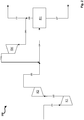
- Figure 1 shows a greatly simplified schematic block flow diagram of a production process for methanol with a recycle gas compressor stage in a synthesis cycle with a single reactor stage and a single compressor stage for fresh gas.
- a first fresh gas stream 101 at a pressure of 34 bar is fed to a first compressor stage K1.
- the fresh gas of the fresh gas stream 101 comes from a feed gas source which provides a feed gas that contains only carbon dioxide with regard to carbon oxides. Due to the molar ratio of carbon dioxide to hydrogen of 3 to 1, a stoichiometric number SN of 2.0 results for the fresh gas of the fresh gas flow 101.
- the fresh gas flow 101 is compressed by the first compressor stage K1, so that a second fresh gas flow 102 results on the pressure side of the compressor stage K1.
- the second fresh gas stream 102 is combined with the recirculation gas stream 104b, which results in a combined gas stream which is referred to here as synthesis gas stream 103.
- the compression by compressor stage K1 has the effect that synthesis gas stream 102 has a pressure of 85.0 bar at the inlet of reactor stage R1.
- Synthesis gas from synthesis gas stream 102 is converted in reactor stage R1 over a copper-based fixed bed catalyst with a catalyst volume of 16.8 m 3 to form methanol.
- the pressure at the reactor outlet of the reactor of R1 is 81.2 bar.
- the conversion is incomplete, as a result of which a stream of unreacted synthesis gas 105 is obtained, which is partially fed as recycle gas stream 104a to recycle gas compressor stage RK and compressed so that recycle gas stream 104b is obtained on the pressure side of recycle gas compressor stage RK.
- reactor stage R1 also has a heat exchanger for cooling the product stream and a separator. By cooling the product stream and condensing methanol in the separator, a product stream 106 comprising methanol is obtained.
- the methanol is in the form of crude methanol and is fed to a suitable work-up depending on the required purity to obtain pure methanol (not shown).
- the carbon dioxide conversion is in the comparative example Figure 1 98.5% and the hydrogen conversion is 98.8%.
- the amount of recirculation gas to be compressed by the recirculation gas compressor stage thus corresponds to three and a half times the amount of fresh gas, in each case based on the standard volume flows of recirculation gas and fresh gas.
- Figure 2 shows a greatly simplified schematic block flow diagram of a production process for methanol with a recycle gas compressor stage in a synthesis cycle with a reactor stage and two series-connected compressor stages for fresh gas.
- the procedure of Figure 2 differs from the procedure of Figure 1 thus exclusively in the use of an additional compressor stage for fresh gas.
- a first fresh gas stream 201 at a pressure of 34 bar is fed to a first compressor stage K1.
- the fresh gas of the fresh gas stream 201 comes from a feed gas source which provides a feed gas that contains only carbon dioxide with regard to carbon oxides. Due to the molar ratio of carbon dioxide to hydrogen of 3 to 1, a stoichiometric number SN of 2.0 results for the fresh gas of the fresh gas flow 101.
- the fresh gas stream 201 is compressed by the first compressor stage K1, so that a second fresh gas stream 202 with a pressure of 65.0 bar results on the pressure side of the compressor stage K1.
- the second fresh gas flow 202 is compressed by the second compressor stage K2, a third fresh gas flow 203 resulting on the pressure side of K2.
- the third fresh gas stream 203 is combined with the recirculation gas stream 206b, which results in a combined gas stream, which here is the synthesis gas stream 204 referred to as.
- the compression by compressor stage K2 has the effect that synthesis gas stream 204 has a pressure of 85.0 bar at the inlet of reactor stage R1.
- Synthesis gas from synthesis gas stream 204 is converted in reactor stage R1 over a copper-based fixed bed catalyst with a catalyst volume of 16.8 m 3 to form methanol.
- the pressure at the reactor outlet is 81.2 bar.
- reactor stage R1 also has a heat exchanger for cooling the product stream and a separator. By cooling the product stream and condensing methanol in the separator, a product stream 207 comprising methanol is obtained.
- the methanol is in the form of raw methanol and, depending on the required purity, is fed to a suitable work-up to obtain pure methanol (not shown).
- the carbon dioxide conversion is in the comparative example Figure 2 likewise 98.5% and the hydrogen conversion is likewise 98.8%.
- t / d crude methanol per day
- a compressor output of 1090 kW for K1 and K2 together and 325 kW for RK are required, which corresponds to a total compressor output of 1415 kW.
- the total compressor output is thus somewhat lower than in the comparative example of Figure 1 , however, three compressor stages K1, K2 and RK are required, which increases the CAPEX of the system.
- Figure 3 shows a greatly simplified schematic block flow diagram of a production process according to the invention for methanol without a recycle gas compressor stage Synthesis circuit, the synthesis circuit comprising a plurality of reactor stages arranged in series.
- a first fresh gas stream 301 at a pressure of 34.0 bar is fed to a first compressor stage K1.
- the fresh gas of the fresh gas stream 301 comes from a feed gas source which, with regard to carbon oxides, provides feed gas containing only carbon dioxide. Due to the molar ratio of carbon dioxide to hydrogen of 3 to 1, a stoichiometric number SN of 2.0 results for the fresh gas of the fresh gas stream 301.
- the first fresh gas stream 301 is compressed by the first compressor stage K1, so that a second fresh gas stream 302 with a pressure of 65.0 bar is obtained on the pressure side of the compressor stage K1.
- the second fresh gas flow 302 is combined with recirculation gas flow 305, resulting in a combined gas flow 303 which is introduced into a second compressor stage K2 and is compressed to a pressure of 85.0 bar.
- a gas flow with synthesis pressure which is referred to here as synthesis gas flow 304, results on the pressure side of the second compressor stage.
- the synthesis gas stream 304 is introduced into a first of a total of four reactor stages R1 to R4 arranged in series.
- synthesis gas 304 is converted to methanol over a copper-based fixed bed catalyst with a catalyst volume of 4.2 m 3.
- the reactor stages R2, R3 and R4 each have a catalyst volume of 4.2 m 3 of the same copper-based catalyst, so that a total catalyst volume of 16.8 m 3 results, which is the catalyst volume of the individual reactor stage in the comparative examples Figure 1 and Figure 2 corresponds.
- a stream of unreacted synthesis gas 306a is obtained, which is introduced into the following reactor stages arranged in series, here in reactor stage R2.
- Reactor stage R1 and further reactor stages R2 to R4 have, in addition to the actual reactor, also a heat exchanger for cooling the product stream and a separator. By cooling the product stream and condensing methanol in the separator, a product stream 307a is obtained in R1.
- unreacted synthesis gas 306a is converted into methanol and by-products in reactor stage R2, whereby a further product stream 307b is obtained.
- Synthesis gas not reacted in the reaction on the copper-based catalyst of R2 is again introduced into the following reactor stage R3, a product stream 307c and unreacted synthesis gas 306c being obtained.
- a small proportion of unreacted synthesis gas R2 is always dissolved in the condensate (methanol) and is not available for the next reactor stage.
- Unreacted synthesis gas 306c is introduced into the last of the reactor stages R4 arranged in series, a further product stream 307d being obtained.
- the product streams 307a to 307d are combined to form a total product stream 307.
- Total product stream 307 has crude methanol which, depending on the required purity, is fed to a suitable work-up for obtaining pure methanol (not shown).
- the pressure at the reactor outlet of reactor stage R4 is 74.9 bar.
- the pressure loss over all reactor stages is thus 10.1 bar.
- Synthesis gas 306d which has not reacted in the last reactor stage is returned directly as recycle gas stream 305 to the second fresh gas stream 302 and is combined with it.
- a part of the unreacted synthesis gas withdrawn in the last reactor stage R4 is used in the example according to Figure 3 branched off as a purge gas stream in order to avoid the accumulation of inert components and by-products in the recycle gas stream 305.
- the carbon dioxide conversion is in the example Figure 3 98.3% and the hydrogen conversion is 98.6%.
- the sales are thus with the sales according to the comparative examples (setup of Figures 1 and 2 ) comparable.
- the recirculation gas amount 305 thus corresponds to 90% of the fresh gas amount 302, in each case based on the standard volume flows of recirculation gas and fresh gas.
- the recirculation rate is therefore lower by a factor of about 3.9 with the same carbon and hydrogen conversion than in the comparative examples, which is due to the higher conversion and the intermediate condensation of products in the majority of the reactor stages (R1 to R4).
- the recirculation rate Due to the substoichiometric fresh gas (H 2 in deficit and carbon dioxide in excess), the recirculation rate surprisingly drops to 0.41, i.e. less than half of the recirculation gas 305 in relation to the fresh gas 302 is required to produce the same amount of raw methanol 307 of 344 tons per day (of which 217.5 t / d methanol, the remainder essentially water) with simultaneously high hydrogen conversion.
- the lower recycle gas amount 305 also leads to a lower amount of purge gas required, which in turn means savings in hydrogen recovery.
- the hydrogen conversion is 98.8% and is therefore comparable with all previous examples.
- the carbon conversion is slightly lower at 89.5%, but this has no impact on the overall economy of the process in view of the low costs of this raw material, especially if it comes from exhaust gas sources.
Landscapes
- Chemical & Material Sciences (AREA)
- Organic Chemistry (AREA)
- Chemical Kinetics & Catalysis (AREA)
- Organic Low-Molecular-Weight Compounds And Preparation Thereof (AREA)
Priority Applications (3)
| Application Number | Priority Date | Filing Date | Title |
|---|---|---|---|
| EP19020480.0A EP3782974B1 (fr) | 2019-08-19 | 2019-08-19 | Procédé et installation de fabrication de méthanol à partir de gaz de synthèse à teneur augmentée en dioxyde de carbone |
| CN202010747689.XA CN112390703B (zh) | 2019-08-19 | 2020-07-28 | 用于从具有高比例的二氧化碳的合成气生产甲醇的方法和设备 |
| US16/996,185 US11078142B2 (en) | 2019-08-19 | 2020-08-18 | Process and plant for producing methanol from synthesis gases having a high proportion of carbon dioxide |
Applications Claiming Priority (1)
| Application Number | Priority Date | Filing Date | Title |
|---|---|---|---|
| EP19020480.0A EP3782974B1 (fr) | 2019-08-19 | 2019-08-19 | Procédé et installation de fabrication de méthanol à partir de gaz de synthèse à teneur augmentée en dioxyde de carbone |
Publications (2)
| Publication Number | Publication Date |
|---|---|
| EP3782974A1 true EP3782974A1 (fr) | 2021-02-24 |
| EP3782974B1 EP3782974B1 (fr) | 2023-03-01 |
Family
ID=67850932
Family Applications (1)
| Application Number | Title | Priority Date | Filing Date |
|---|---|---|---|
| EP19020480.0A Active EP3782974B1 (fr) | 2019-08-19 | 2019-08-19 | Procédé et installation de fabrication de méthanol à partir de gaz de synthèse à teneur augmentée en dioxyde de carbone |
Country Status (3)
| Country | Link |
|---|---|
| US (1) | US11078142B2 (fr) |
| EP (1) | EP3782974B1 (fr) |
| CN (1) | CN112390703B (fr) |
Cited By (2)
| Publication number | Priority date | Publication date | Assignee | Title |
|---|---|---|---|---|
| CN115253941A (zh) * | 2022-03-23 | 2022-11-01 | 中石化宁波工程有限公司 | 一种提高二氧化碳制甲醇转化率的装置及方法 |
| WO2026041662A1 (fr) * | 2024-08-22 | 2026-02-26 | Linde Gmbh | Procédé et système de production de méthanol |
Families Citing this family (2)
| Publication number | Priority date | Publication date | Assignee | Title |
|---|---|---|---|---|
| EP3782973B1 (fr) * | 2019-08-19 | 2023-03-01 | L'air Liquide, Société Anonyme Pour L'Étude Et L'exploitation Des Procédés Georges Claude | Procédé et installation de fabrication de méthanol |
| EP4703343A1 (fr) * | 2024-08-30 | 2026-03-04 | L'air Liquide, Societe Anonyme Pour L'etude Et L'exploitation Des Procedes Georges Claude | Procédé de préparation de méthanol |
Citations (3)
| Publication number | Priority date | Publication date | Assignee | Title |
|---|---|---|---|---|
| EP2116295A1 (fr) | 2008-04-16 | 2009-11-11 | Methanol Casale S.A. | Procédé de production de méthanol à partir du reformage à la vapeur |
| WO2015193440A1 (fr) | 2014-06-20 | 2015-12-23 | Haldor Topsøe A/S | Réacteurs de méthanol en série |
| WO2017167642A1 (fr) | 2016-03-30 | 2017-10-05 | Haldor Topsøe A/S | Conception de processus de synthèse de méthanol pour grande capacité de production |
Family Cites Families (2)
| Publication number | Priority date | Publication date | Assignee | Title |
|---|---|---|---|---|
| EP3205622B1 (fr) * | 2016-02-11 | 2018-05-09 | Ulrich Wagner | Procede de synthese de methanol |
| EP3782973B1 (fr) * | 2019-08-19 | 2023-03-01 | L'air Liquide, Société Anonyme Pour L'Étude Et L'exploitation Des Procédés Georges Claude | Procédé et installation de fabrication de méthanol |
-
2019
- 2019-08-19 EP EP19020480.0A patent/EP3782974B1/fr active Active
-
2020
- 2020-07-28 CN CN202010747689.XA patent/CN112390703B/zh active Active
- 2020-08-18 US US16/996,185 patent/US11078142B2/en active Active
Patent Citations (3)
| Publication number | Priority date | Publication date | Assignee | Title |
|---|---|---|---|---|
| EP2116295A1 (fr) | 2008-04-16 | 2009-11-11 | Methanol Casale S.A. | Procédé de production de méthanol à partir du reformage à la vapeur |
| WO2015193440A1 (fr) | 2014-06-20 | 2015-12-23 | Haldor Topsøe A/S | Réacteurs de méthanol en série |
| WO2017167642A1 (fr) | 2016-03-30 | 2017-10-05 | Haldor Topsøe A/S | Conception de processus de synthèse de méthanol pour grande capacité de production |
Cited By (2)
| Publication number | Priority date | Publication date | Assignee | Title |
|---|---|---|---|---|
| CN115253941A (zh) * | 2022-03-23 | 2022-11-01 | 中石化宁波工程有限公司 | 一种提高二氧化碳制甲醇转化率的装置及方法 |
| WO2026041662A1 (fr) * | 2024-08-22 | 2026-02-26 | Linde Gmbh | Procédé et système de production de méthanol |
Also Published As
| Publication number | Publication date |
|---|---|
| US11078142B2 (en) | 2021-08-03 |
| US20210053898A1 (en) | 2021-02-25 |
| CN112390703B (zh) | 2024-12-13 |
| CN112390703A (zh) | 2021-02-23 |
| EP3782974B1 (fr) | 2023-03-01 |
Similar Documents
| Publication | Publication Date | Title |
|---|---|---|
| EP3782974B1 (fr) | Procédé et installation de fabrication de méthanol à partir de gaz de synthèse à teneur augmentée en dioxyde de carbone | |
| EP2281793B1 (fr) | Procédé et installation destinés à la fabrication de méthanol | |
| EP3426601B1 (fr) | Procédé et installation pour la production d'un produit gazeux sous des conditions de charge variables | |
| DE2549439C2 (fr) | ||
| EP3307675B1 (fr) | Procédé multipression pour la production d'ammoniac | |
| DE10057863C2 (de) | Mehrdruckverfahren zur Herstellung von Ammoniak | |
| EP1773483B1 (fr) | Procede pour effectuer des reaction en phase gazeuse exothermiques catalytiques heterogenes | |
| EP4324815A1 (fr) | Procédé et installation de production de méthanol et de gaz de synthèse | |
| EP2539307A1 (fr) | Procédé de production de méthanol | |
| DE102016213668A1 (de) | Verfahren und Anlage zur Herstellung von Alkoholen oder Kohlenwasserstoffen | |
| EP3219697B1 (fr) | Synthese de methanol a partir de gaz de synthese ayant un manque d'hydrogene | |
| EP3741738B1 (fr) | Procédé de fabrication de méthanol | |
| WO2020229261A1 (fr) | Procédé et installation de synthèse de méthanol | |
| EP4197994A1 (fr) | Procédé et installation de production de méthanol | |
| EP3816145B1 (fr) | Procédé et système de fabrication de méthanol à partir de gaz de synthèse riche en hydrogène | |
| EP3782973B1 (fr) | Procédé et installation de fabrication de méthanol | |
| EP3020696B1 (fr) | Procede de fabrication d'un ou plusieurs produits de reaction | |
| DE3521304A1 (de) | Verfahren zur erzeugung eines synthesegases | |
| EP4324786A1 (fr) | Procédé et installation pour la préparation de gaz de synthèse et pour la production de méthanol | |
| WO2023156444A1 (fr) | Synthèse électrochimique et chimique d'ammoniac | |
| DE2904008C2 (fr) | ||
| DE102015208128A1 (de) | Asymmetrische Kreislaufkaskaden in der Gaskatalyse | |
| EP4606764A1 (fr) | Fourniture et reformage de méthanol | |
| EP4635908A1 (fr) | Procédé et installation de production d'un produit d'hydrogène à l'aide d'ammoniac | |
| DE102023108298A1 (de) | Mengenmäßig optimierte Herstellung von Methanol und daraus Formaldehyd-Harnstoff in einer kombinierten Ammoniak-Harnstoff-Anlage |
Legal Events
| Date | Code | Title | Description |
|---|---|---|---|
| PUAI | Public reference made under article 153(3) epc to a published international application that has entered the european phase |
Free format text: ORIGINAL CODE: 0009012 |
|
| STAA | Information on the status of an ep patent application or granted ep patent |
Free format text: STATUS: THE APPLICATION HAS BEEN PUBLISHED |
|
| AK | Designated contracting states |
Kind code of ref document: A1 Designated state(s): AL AT BE BG CH CY CZ DE DK EE ES FI FR GB GR HR HU IE IS IT LI LT LU LV MC MK MT NL NO PL PT RO RS SE SI SK SM TR |
|
| AX | Request for extension of the european patent |
Extension state: BA ME |
|
| STAA | Information on the status of an ep patent application or granted ep patent |
Free format text: STATUS: REQUEST FOR EXAMINATION WAS MADE |
|
| 17P | Request for examination filed |
Effective date: 20210824 |
|
| RBV | Designated contracting states (corrected) |
Designated state(s): AL AT BE BG CH CY CZ DE DK EE ES FI FR GB GR HR HU IE IS IT LI LT LU LV MC MK MT NL NO PL PT RO RS SE SI SK SM TR |
|
| GRAP | Despatch of communication of intention to grant a patent |
Free format text: ORIGINAL CODE: EPIDOSNIGR1 |
|
| STAA | Information on the status of an ep patent application or granted ep patent |
Free format text: STATUS: GRANT OF PATENT IS INTENDED |
|
| RIC1 | Information provided on ipc code assigned before grant |
Ipc: C07C 31/04 20060101ALI20220901BHEP Ipc: C07C 29/151 20060101AFI20220901BHEP |
|
| INTG | Intention to grant announced |
Effective date: 20220921 |
|
| GRAS | Grant fee paid |
Free format text: ORIGINAL CODE: EPIDOSNIGR3 |
|
| GRAA | (expected) grant |
Free format text: ORIGINAL CODE: 0009210 |
|
| STAA | Information on the status of an ep patent application or granted ep patent |
Free format text: STATUS: THE PATENT HAS BEEN GRANTED |
|
| AK | Designated contracting states |
Kind code of ref document: B1 Designated state(s): AL AT BE BG CH CY CZ DE DK EE ES FI FR GB GR HR HU IE IS IT LI LT LU LV MC MK MT NL NO PL PT RO RS SE SI SK SM TR |
|
| REG | Reference to a national code |
Ref country code: GB Ref legal event code: FG4D Free format text: NOT ENGLISH |
|
| REG | Reference to a national code |
Ref country code: CH Ref legal event code: EP Ref country code: AT Ref legal event code: REF Ref document number: 1550881 Country of ref document: AT Kind code of ref document: T Effective date: 20230315 |
|
| REG | Reference to a national code |
Ref country code: DE Ref legal event code: R096 Ref document number: 502019007062 Country of ref document: DE |
|
| REG | Reference to a national code |
Ref country code: IE Ref legal event code: FG4D Free format text: LANGUAGE OF EP DOCUMENT: GERMAN |
|
| REG | Reference to a national code |
Ref country code: NO Ref legal event code: T2 Effective date: 20230301 |
|
| REG | Reference to a national code |
Ref country code: NL Ref legal event code: FP |
|
| REG | Reference to a national code |
Ref country code: LT Ref legal event code: MG9D |
|
| PG25 | Lapsed in a contracting state [announced via postgrant information from national office to epo] |
Ref country code: RS Free format text: LAPSE BECAUSE OF FAILURE TO SUBMIT A TRANSLATION OF THE DESCRIPTION OR TO PAY THE FEE WITHIN THE PRESCRIBED TIME-LIMIT Effective date: 20230301 Ref country code: LV Free format text: LAPSE BECAUSE OF FAILURE TO SUBMIT A TRANSLATION OF THE DESCRIPTION OR TO PAY THE FEE WITHIN THE PRESCRIBED TIME-LIMIT Effective date: 20230301 Ref country code: LT Free format text: LAPSE BECAUSE OF FAILURE TO SUBMIT A TRANSLATION OF THE DESCRIPTION OR TO PAY THE FEE WITHIN THE PRESCRIBED TIME-LIMIT Effective date: 20230301 Ref country code: HR Free format text: LAPSE BECAUSE OF FAILURE TO SUBMIT A TRANSLATION OF THE DESCRIPTION OR TO PAY THE FEE WITHIN THE PRESCRIBED TIME-LIMIT Effective date: 20230301 Ref country code: ES Free format text: LAPSE BECAUSE OF FAILURE TO SUBMIT A TRANSLATION OF THE DESCRIPTION OR TO PAY THE FEE WITHIN THE PRESCRIBED TIME-LIMIT Effective date: 20230301 |
|
| PG25 | Lapsed in a contracting state [announced via postgrant information from national office to epo] |
Ref country code: SE Free format text: LAPSE BECAUSE OF FAILURE TO SUBMIT A TRANSLATION OF THE DESCRIPTION OR TO PAY THE FEE WITHIN THE PRESCRIBED TIME-LIMIT Effective date: 20230301 Ref country code: PL Free format text: LAPSE BECAUSE OF FAILURE TO SUBMIT A TRANSLATION OF THE DESCRIPTION OR TO PAY THE FEE WITHIN THE PRESCRIBED TIME-LIMIT Effective date: 20230301 Ref country code: GR Free format text: LAPSE BECAUSE OF FAILURE TO SUBMIT A TRANSLATION OF THE DESCRIPTION OR TO PAY THE FEE WITHIN THE PRESCRIBED TIME-LIMIT Effective date: 20230602 Ref country code: FI Free format text: LAPSE BECAUSE OF FAILURE TO SUBMIT A TRANSLATION OF THE DESCRIPTION OR TO PAY THE FEE WITHIN THE PRESCRIBED TIME-LIMIT Effective date: 20230301 |
|
| PG25 | Lapsed in a contracting state [announced via postgrant information from national office to epo] |
Ref country code: SM Free format text: LAPSE BECAUSE OF FAILURE TO SUBMIT A TRANSLATION OF THE DESCRIPTION OR TO PAY THE FEE WITHIN THE PRESCRIBED TIME-LIMIT Effective date: 20230301 Ref country code: RO Free format text: LAPSE BECAUSE OF FAILURE TO SUBMIT A TRANSLATION OF THE DESCRIPTION OR TO PAY THE FEE WITHIN THE PRESCRIBED TIME-LIMIT Effective date: 20230301 Ref country code: PT Free format text: LAPSE BECAUSE OF FAILURE TO SUBMIT A TRANSLATION OF THE DESCRIPTION OR TO PAY THE FEE WITHIN THE PRESCRIBED TIME-LIMIT Effective date: 20230703 Ref country code: EE Free format text: LAPSE BECAUSE OF FAILURE TO SUBMIT A TRANSLATION OF THE DESCRIPTION OR TO PAY THE FEE WITHIN THE PRESCRIBED TIME-LIMIT Effective date: 20230301 Ref country code: CZ Free format text: LAPSE BECAUSE OF FAILURE TO SUBMIT A TRANSLATION OF THE DESCRIPTION OR TO PAY THE FEE WITHIN THE PRESCRIBED TIME-LIMIT Effective date: 20230301 |
|
| PG25 | Lapsed in a contracting state [announced via postgrant information from national office to epo] |
Ref country code: SK Free format text: LAPSE BECAUSE OF FAILURE TO SUBMIT A TRANSLATION OF THE DESCRIPTION OR TO PAY THE FEE WITHIN THE PRESCRIBED TIME-LIMIT Effective date: 20230301 Ref country code: IS Free format text: LAPSE BECAUSE OF FAILURE TO SUBMIT A TRANSLATION OF THE DESCRIPTION OR TO PAY THE FEE WITHIN THE PRESCRIBED TIME-LIMIT Effective date: 20230701 |
|
| REG | Reference to a national code |
Ref country code: DE Ref legal event code: R097 Ref document number: 502019007062 Country of ref document: DE |
|
| PLBE | No opposition filed within time limit |
Free format text: ORIGINAL CODE: 0009261 |
|
| STAA | Information on the status of an ep patent application or granted ep patent |
Free format text: STATUS: NO OPPOSITION FILED WITHIN TIME LIMIT |
|
| PG25 | Lapsed in a contracting state [announced via postgrant information from national office to epo] |
Ref country code: SI Free format text: LAPSE BECAUSE OF FAILURE TO SUBMIT A TRANSLATION OF THE DESCRIPTION OR TO PAY THE FEE WITHIN THE PRESCRIBED TIME-LIMIT Effective date: 20230301 Ref country code: DK Free format text: LAPSE BECAUSE OF FAILURE TO SUBMIT A TRANSLATION OF THE DESCRIPTION OR TO PAY THE FEE WITHIN THE PRESCRIBED TIME-LIMIT Effective date: 20230301 |
|
| 26N | No opposition filed |
Effective date: 20231204 |
|
| PG25 | Lapsed in a contracting state [announced via postgrant information from national office to epo] |
Ref country code: MC Free format text: LAPSE BECAUSE OF FAILURE TO SUBMIT A TRANSLATION OF THE DESCRIPTION OR TO PAY THE FEE WITHIN THE PRESCRIBED TIME-LIMIT Effective date: 20230301 |
|
| REG | Reference to a national code |
Ref country code: CH Ref legal event code: PL |
|
| PG25 | Lapsed in a contracting state [announced via postgrant information from national office to epo] |
Ref country code: MC Free format text: LAPSE BECAUSE OF FAILURE TO SUBMIT A TRANSLATION OF THE DESCRIPTION OR TO PAY THE FEE WITHIN THE PRESCRIBED TIME-LIMIT Effective date: 20230301 |
|
| PG25 | Lapsed in a contracting state [announced via postgrant information from national office to epo] |
Ref country code: LU Free format text: LAPSE BECAUSE OF NON-PAYMENT OF DUE FEES Effective date: 20230819 |
|
| GBPC | Gb: european patent ceased through non-payment of renewal fee |
Effective date: 20230819 |
|
| PG25 | Lapsed in a contracting state [announced via postgrant information from national office to epo] |
Ref country code: LU Free format text: LAPSE BECAUSE OF NON-PAYMENT OF DUE FEES Effective date: 20230819 Ref country code: CH Free format text: LAPSE BECAUSE OF NON-PAYMENT OF DUE FEES Effective date: 20230831 |
|
| REG | Reference to a national code |
Ref country code: IE Ref legal event code: MM4A |
|
| PG25 | Lapsed in a contracting state [announced via postgrant information from national office to epo] |
Ref country code: IT Free format text: LAPSE BECAUSE OF FAILURE TO SUBMIT A TRANSLATION OF THE DESCRIPTION OR TO PAY THE FEE WITHIN THE PRESCRIBED TIME-LIMIT Effective date: 20230301 |
|
| PG25 | Lapsed in a contracting state [announced via postgrant information from national office to epo] |
Ref country code: IE Free format text: LAPSE BECAUSE OF NON-PAYMENT OF DUE FEES Effective date: 20230819 |
|
| PG25 | Lapsed in a contracting state [announced via postgrant information from national office to epo] |
Ref country code: GB Free format text: LAPSE BECAUSE OF NON-PAYMENT OF DUE FEES Effective date: 20230819 |
|
| PG25 | Lapsed in a contracting state [announced via postgrant information from national office to epo] |
Ref country code: IE Free format text: LAPSE BECAUSE OF NON-PAYMENT OF DUE FEES Effective date: 20230819 Ref country code: GB Free format text: LAPSE BECAUSE OF NON-PAYMENT OF DUE FEES Effective date: 20230819 |
|
| PG25 | Lapsed in a contracting state [announced via postgrant information from national office to epo] |
Ref country code: BG Free format text: LAPSE BECAUSE OF FAILURE TO SUBMIT A TRANSLATION OF THE DESCRIPTION OR TO PAY THE FEE WITHIN THE PRESCRIBED TIME-LIMIT Effective date: 20230301 |
|
| PG25 | Lapsed in a contracting state [announced via postgrant information from national office to epo] |
Ref country code: BG Free format text: LAPSE BECAUSE OF FAILURE TO SUBMIT A TRANSLATION OF THE DESCRIPTION OR TO PAY THE FEE WITHIN THE PRESCRIBED TIME-LIMIT Effective date: 20230301 |
|
| PG25 | Lapsed in a contracting state [announced via postgrant information from national office to epo] |
Ref country code: CY Free format text: LAPSE BECAUSE OF FAILURE TO SUBMIT A TRANSLATION OF THE DESCRIPTION OR TO PAY THE FEE WITHIN THE PRESCRIBED TIME-LIMIT; INVALID AB INITIO Effective date: 20190819 |
|
| PG25 | Lapsed in a contracting state [announced via postgrant information from national office to epo] |
Ref country code: HU Free format text: LAPSE BECAUSE OF FAILURE TO SUBMIT A TRANSLATION OF THE DESCRIPTION OR TO PAY THE FEE WITHIN THE PRESCRIBED TIME-LIMIT; INVALID AB INITIO Effective date: 20190819 |
|
| PGFP | Annual fee paid to national office [announced via postgrant information from national office to epo] |
Ref country code: NL Payment date: 20250821 Year of fee payment: 7 |
|
| PGFP | Annual fee paid to national office [announced via postgrant information from national office to epo] |
Ref country code: DE Payment date: 20250820 Year of fee payment: 7 |
|
| PGFP | Annual fee paid to national office [announced via postgrant information from national office to epo] |
Ref country code: NO Payment date: 20250826 Year of fee payment: 7 |
|
| PGFP | Annual fee paid to national office [announced via postgrant information from national office to epo] |
Ref country code: BE Payment date: 20250820 Year of fee payment: 7 |
|
| PGFP | Annual fee paid to national office [announced via postgrant information from national office to epo] |
Ref country code: AT Payment date: 20250821 Year of fee payment: 7 Ref country code: FR Payment date: 20250828 Year of fee payment: 7 |
|
| PG25 | Lapsed in a contracting state [announced via postgrant information from national office to epo] |
Ref country code: TR Free format text: LAPSE BECAUSE OF FAILURE TO SUBMIT A TRANSLATION OF THE DESCRIPTION OR TO PAY THE FEE WITHIN THE PRESCRIBED TIME-LIMIT Effective date: 20230301 |