EP3783294A1 - Zielfernrohr-montagesystem mit verriegelungshebel - Google Patents
Zielfernrohr-montagesystem mit verriegelungshebel Download PDFInfo
- Publication number
- EP3783294A1 EP3783294A1 EP20186863.5A EP20186863A EP3783294A1 EP 3783294 A1 EP3783294 A1 EP 3783294A1 EP 20186863 A EP20186863 A EP 20186863A EP 3783294 A1 EP3783294 A1 EP 3783294A1
- Authority
- EP
- European Patent Office
- Prior art keywords
- housing
- locking lever
- mounting system
- telescopic sight
- flank
- Prior art date
- Legal status (The legal status is an assumption and is not a legal conclusion. Google has not performed a legal analysis and makes no representation as to the accuracy of the status listed.)
- Granted
Links
Images




Classifications
-
- F—MECHANICAL ENGINEERING; LIGHTING; HEATING; WEAPONS; BLASTING
- F41—WEAPONS
- F41G—WEAPON SIGHTS; AIMING
- F41G11/00—Details of sighting or aiming apparatus; Accessories
- F41G11/001—Means for mounting tubular or beam shaped sighting or aiming devices on firearms
- F41G11/003—Mountings with a dove tail element, e.g. "Picatinny rail systems"
Definitions
- the present invention relates to a telescopic sight mounting system which can be clamped onto a standardized Picatinny rail by means of an adjustable lever system and which can be used for transport purposes.
- devices such as a telescopic sight, laser sight and lamp are attached to the Picatinny rail with the necessary locking steps.
- the devices used for the various purposes for example in areas such as hunting, shooting sports or the like, vary depending on the area of application. Therefore, the attachment to the rifle requires different locking methods for each application.
- the telescopic sight clamps or similar parts are attached to the Picatinny rail by means of clamping screws. As soon as the riflescope is optimally placed, further assembly processes are carried out. However, this is difficult and time consuming to use.
- the components of the generic telescopic sight mounting systems are positioned so that they can be moved forwards and backwards. The locking levers used in this position require an additional safety system to absorb the recoil force that arises after the shot. For this reason, additional setup is required.
- the object of this invention is to provide a telescopic sight mounting system which enables locking via a self-adjusting lever only by pressing a finger.
- the other object of this invention is to provide a telescopic sight mounting system which can be mounted in a short time.
- the telescopic sight With the telescopic sight mounting system, the telescopic sight is positioned inside the housing (1). It is then fastened inside the housing (1) by tightening the screws (8) on the housing (1).
- the channel which is arranged on the underside of the housing (1) is first arranged on the Picatinny rail. The housing protrusion (10) on one side of the channel engages in the Picatinny rail.
- the flank (2) is attached to the recess that is made perpendicular to the channel.
- the springs (7) are positioned between the flank (2) and the housing (1).
- the threaded end of the locking screw (3) runs through the recess through the hole made in the flank (2) and then emerges outward from the housing (1).
- An adjusting nut (4) is attached to this threaded end of the locking screw (3), which protrudes outward from the housing (1). Tightening the adjusting nut (4) enables the flank (2) to be fastened to the housing (1).
- the specially designed adjusting nut (4) controls how much force the flank (2) exerts on the edge of the Picatinny rail. This adjusting nut (4) is designed so that it has 12 steps in the form of teeth and a distance of 30 degrees is between all steps. While the adjusting nut is being tightened, pressure is exerted on the springs (7).
- the locking lever (5) is attached to the head-shaped end of the locking screw (3) with a pin (6).
- the pin (6) runs through the hole in the locking lever (12) and through the hole in the locking screw (3) at the head-shaped end.
- a rotary movement of the locking lever (5) at the head-shaped end of the locking screw (3) can be implemented by means of this pin (6).
- the distance between the side surface of the locking lever (13) and the hole in the locking lever (12) is smaller than the distance between the surface of the locking lever (11) and the hole in the locking lever (12).
- the side surface of the locking lever (13) comes to rest on the flank (2), while the locking lever (5) is not active.
- the locking lever (5) is moved in a rotating manner, the surface of the locking lever (11) begins to come into contact with the flank (2). Since the bore of the locking lever (12) remains fixed with respect to the head-shaped end, the flank (2) is shifted in the direction of the housing projection (10) and the locking is made possible.
- connection (locking) of the riflescope mounting system with the Picatinny rail can be carried out entirely by hand and no additional equipment (such as keys, screwdrivers and the like) is necessary. Unlocking or releasing the lock, including locking on large-caliber weapons, of the specially designed locking lever (5), which secures itself during its locked state, is not possible, with the exception of unlocking by external intervention by hand (finger).
- the specially designed locking lever (5) is unlocked by turning it through 68 degrees. Therefore, the product is advantageous over other generic systems which require a 180 degree rotation.
- the specially designed locking lever (5) can be moved up and down. In this way, increased aesthetics and more practical usability are provided.
- This telescopic sight mounting system ensures precise adjustment of the mounting product without the use of an additional tool.
- the locking lever (5) secures itself thanks to its design without the need for an additional component and enables quick and practical locking in a small installation space. Since the The locking lever (5) is positioned horizontally (not parallel) with respect to the direction of the shot (with respect to the recoil force that occurs after the shot), it is self-locking.
- the ball (14) is arranged in the housing between the outer circumference of the adjusting nut (4) and an adjusting screw (15). In this way, the ball (14) can be secured in the housing and a force can be applied to the ball (14) by means of the adjusting screw (15) so that the ball (14) slides into the recesses of the adjusting nut (4).
- the adjusting screw (15) is preferably arranged in a recess in the housing such that the axis of rotation of the adjusting screw (15) is arranged perpendicular to the axis of rotation of the adjusting nut (4).
- the ball (14) By tightening the adjusting screw (15), the ball (14) can be fixed in a recess and the adjusting nut (4) can also be fixed in its position, since a further rotary movement is caused by the engagement of the fixed ball (14) in a recess in the adjusting nut (4 ) is prevented.
- an adjusting spring (16) between the ball (14) and the adjusting screw (15), as in Fig. 6 and Fig. 7 shown, is arranged.
- This adjusting spring (16) can apply a spring force to the ball (14), with the ball (14) sliding into the recesses of the adjusting nut (4) due to the spring force without fixing the ball (14) in a recess and thus the rotation the adjusting nut (4), as the adjusting nut (4) can be turned further against the resistance of the spring force of the adjusting spring (16).
- the operator receives both a direct haptic feedback via the adjusting nut (4) during the adjustment of the telescopic sight mounting system, caused by overcoming the spring force necessary to set the next level, as well as an acoustic feedback due to the audible click with every turn of the adjusting nut (4) by one step.
- the step setting with the proposed solution can be done in a simple manner, without additional tools, while at the same time minimizing errors due to the direct feedback via the adjusting nut (4) during the setting.
Landscapes
- Engineering & Computer Science (AREA)
- General Engineering & Computer Science (AREA)
- Aiming, Guidance, Guns With A Light Source, Armor, Camouflage, And Targets (AREA)
- Mutual Connection Of Rods And Tubes (AREA)
- Clamps And Clips (AREA)
Abstract
Description
- Die vorliegende Erfindung betrifft ein Zielfernrohr-Montagesystem, das mittels eines einstellbaren Hebelsystems auf einer standardisierten Picatinny-Schiene durch Einklemmen montiert werden kann und das für Transportzwecke verwendet werden kann.
- Gemäß dem Stand der Technik werden Einrichtungen wie Zielfernrohr, Laservisier und Lampe mit den erforderlichen Verriegelungsschritten auf der Picatinny-Schiene befestigt. Die für die verschiedenen Verwendungszwecke, beispielsweise in Bereichen wie Jagdsport, Schießsport oder dergleichen, verwendeten Einrichtungen variieren je nach Einsatzgebiet. Daher erfordert die Befestigung auf dem Gewehr unterschiedliche Verriegelungsverfahren für jedes Einsatzgebiet.
- Gemäß Stand der Technik wurden verschiedene Verbesserungen bezüglich der Zielfernrohr-Montagesysteme vorgenommen.
- Aus dem im Stand der Technik vorhandenen Patentdokument
US 7,559,167 B1 sind Vorrichtungen, Systeme und Verfahren zum Verwenden und Installieren von Zubehörhalterungen, insbesondere mit Picatinny-Schiene, an Griffen von Schusswaffen bekannt, wobei die Zubehörhalterungen z.B. Leuchten, Laser, Bajonette oder ähnliches tragen können. - In dem im Stand der Technik vorhandenen Patentdokument
US 6,931,779 B1 werden Visiereinrichtungen für Feuerwaffen und insbesondere eine Montageeinrichtung für Feuerwaffen, die die Montage eines Zielfernrohrs oder eines Nachtsichtgeräts ermöglicht und die ein niedriges Profil in Bezug auf das Gehäuse aufweist, erwähnt. - In dem im Stand der Technik vorhandenen Patentdokument
US 5,533,267 A wird ein verbessertes Montageverfahren für ein Zielfernrohr auf einer Pistole erwähnt. - Aus dem im Stand der Technik vorhandenen Patentdokument
DE 41 33 242 C1 ist eine lösbar an einem Gewehr anbringbare Montagevorrichtung für ein Zielfernrohr bekannt, deren hintere Füße in einer hinteren Ausnehmung verriegelbar sind. - Jedoch werden bei den im Stand der Technik vorhandenen Montagesystemen die Zielfernrohrschellen oder ähnliche Teile mittels Klemmschrauben auf der Picatinny-Schiene befestigt. Sobald das Zielfernrohr optimal platziert ist, werden weitere Montagevorgänge durchgeführt. Dies ist jedoch schwierig und zeitaufwendig hinsichtlich der Verwendung. Außerdem sind die Bauteile der gattungsgemäßen Zielfernrohr-Montagesysteme so positioniert, dass sie vorwärts und rückwärts beweglich sind. Die in dieser Position verwendeten Verriegelungshebel benötigen ein zusätzliches Sicherungssystem, um die Rückstoßkraft zu absorbieren, die nach dem Schuss entsteht. Aus diesem Grund ist eine zusätzliche Einrichtung erforderlich.
- Die Aufgabe dieser Erfindung ist es, ein Zielfernrohr-Montagesystem bereitzustellen, das über einen selbsteinstellenden Hebel nur mittels eines Fingerdruckes eine Verriegelung ermöglicht.
- Die andere Aufgabe dieser Erfindung ist es, ein Zielfernrohr-Montagesystem bereitzustellen, das in kurzer Zeit montiert werden kann.
- Das zur Lösung der Aufgabe dieser Erfindung bereitgestellte Zielfernrohr-Montagesystem wird anhand der beigefügten Figuren dargestellt.
- Es zeigen:
- Fig. 1
- eine schematische Seitenansicht des Zielfernrohr-Montagesystems;
- Fig. 2
- eine Explosionsdarstellung des Gehäuses in Ansicht von unten;
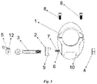
- Fig. 3
- eine Explosionsdarstellung des Zielfernrohr-Montagesystems in Seitenansicht;
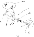
- Fig. 4
- eine Explosionsdarstellung des Zielfernrohr-Montagesystems in perspektivischer Ansicht;
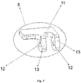
- Fig. 5
- eine schematische Ansicht des Verriegelungshebels;
- Fig. 6
- eine alternative Ausführungsform des Zielfernrohr-Montagesystems in seitlicher Ansicht;
- Fig. 7
- eine Explosionsdarstellung des Zielfernrohr-Montagesystems gemäß
Fig. 6 in perspektivischer Ansicht. - Die Teile, die in den Zeichnungen vorhanden sind, sind einzeln nummeriert und die entsprechenden Bezeichnungen werden nachfolgend angegeben.
- 1. Gehäuse
- 2. Flanke
- 3. Verriegelungsschraube
- 4. Stellmutter
- 5. Verriegelungshebel
- 6. Stift
- 7. Feder
- 8. Schraube
- 9. Flankenvorsprung
- 10. Gehäusevorsprung
- 11. Oberfläche des Verriegelungshebels
- 12. Bohrung des Verriegelungshebels
- 13. Seitenfläche des Verriegelungshebels
- 14. Kugel
- 15. Stellschraube
- 16. Stellfeder
- Das erfindungsgemäße Zielfernrohr-Montagesystem umfasst:
- ein Gehäuse (1), das an der Picatinny-Schiene anbringbar ist, indem der an dessen Unterseite vorhandene Kanal an der Picatinny-Schiene befestigbar ist, und an dessen einer Seite sich eine Ausnehmung vertikal zum Kanal befindet, einen Gehäusevorsprung (10), der an einer Seite des Kanals an der Unterseite des Gehäuses (1) angeordnet ist,
- eine Flanke (2), welche in der Ausnehmung, die vertikal zum an der Unterseite des Gehäuses (1) befindlichen Kanal angeordnet ist, in Richtung des Gehäusevorsprungs (10) vorwärts und rückwärts beweglich ist,
- eine Verriegelungsschraube (3) mit einem mit einem Gewinde versehenen Ende und mit einem anderen kopfförmigen Ende, die zuerst durch die Flanke (2) und danach durch das Gehäuse (1) verläuft, wobei sich das mit einem Gewinde versehene Ende aus dem Gehäuse (1) heraus erstreckt,
- eine an dem sich aus dem Gehäuse (1) heraus erstreckenden mit einem Gewinde versehenen Ende der Verriegelungsschraube (3) anbringbare Stellmutter (4),
- ein Verriegelungshebel (5) mit einer Bohrung des Verriegelungshebels (12) zur Verbindung mit dem kopfförmigen Ende der Verriegelungsschraube (3) mittels eines Stiftes (6), mit einer Oberfläche des Verriegelungshebels (11) und einer Seitenfläche des Verriegelungshebels (13), wobei der Abstand der Bohrung des Verriegelungshebels (12) zu der Oberfläche des Verriegelungshebels (11) größer ist als der Abstand zu der Seitenfläche des Verriegelungshebels (13),
- eine Feder (7), die in der vertikal zum Kanal angeordneten Ausnehmung angeordnet ist und deren eines Ende an dem Gehäuse (1) anliegt und deren anderes Ende an der Flanke (2) anliegt,
- eine Schraube (8), die in die Hohlräume an der Oberseite des Gehäuses (1) passt und mittels der der Zielfernrohr-Tubus mit dem Gehäuse (1) verbindbar ist,
- ein Flankenvorsprung (9), der an der Flanke (2) angeordnet ist und dem Gehäusevorsprung (10) entspricht, wobei mittels des Flankenvorsprungs (9) die Flanke (2) und somit das mit der Flanke (2) verbundene Gehäuse (1) auf der Picatinny-Schiene befestigbar ist.
- Beim Zielfernrohr-Montagesystem wird das Zielfernrohr innerhalb des Gehäuses (1) positioniert. Anschließend wird es durch Anziehen der Schrauben (8), die am Gehäuse (1) vorhanden sind, innerhalb des Gehäuses (1) befestigt. Um das Gehäuse (1) an der Picatinny-Schiene zu befestigen, wird zuerst der Kanal, der an der Unterseite des Gehäuses (1) angeordnet ist, an der Picatinny-Schiene angeordnet. Der an einer Seite des Kanals befindliche Gehäusevorsprung (10) greift in die Picatinny-Schiene ein.
- Die Flanke (2) wird an der Ausnehmung angebracht, die senkrecht zum Kanal eingebracht ist. Gleichzeitig werden die Federn (7) zwischen der Flanke (2) und dem Gehäuse (1) positioniert. Das mit einem Gewinde versehene Ende der Verriegelungsschraube (3) wird durch die Ausnehmung verlaufend durch die Bohrung, die in die Flanke (2) eingebracht ist, geführt und tritt dann nach außen aus dem Gehäuse (1) aus. An diesem mit einem Gewinde versehenen Ende der Verriegelungsschraube (3), das nach außen aus dem Gehäuse (1) heraustritt, wird eine Stellmutter (4) angebracht. Mit dem Anziehen der Stellmutter (4) wird die Befestigung der Flanke (2) an dem Gehäuse (1) ermöglicht. Die speziell gestaltete Stellmutter (4) steuert, wie viel Kraft die Flanke (2) auf den Rand der Picatinny-Schiene ausübt. Diese Stellmutter (4) ist so ausgebildet, dass sie 12 Stufen in Form von Zähnen aufweist und ein Abstand von 30 Grad zwischen allen Stufen liegt. Während des Anziehens der Stellmutter wird auf die Federn (7) ein Druck ausgeübt.
- Der Verriegelungshebel (5) wird mit einem Stift (6) an dem kopfförmigen Ende der Verriegelungsschraube (3) angebracht. Zur Befestigung des Verriegelungshebels (5) an der Verriegelungsschraube (3) verläuft der Stift (6) durch die Bohrung des Verriegelungshebels (12) und durch die an dem kopfförmigen Ende vorhandene Bohrung der Verriegelungsschraube (3). Mittels dieses Stiftes (6) kann eine Drehbewegung des Verriegelungshebels (5) an dem kopfförmigen Ende der Verriegelungsschraube (3) realisiert werden.
- Der Abstand der Seitenfläche des Verriegelungshebels (13) zur Bohrung des Verriegelungshebels (12) ist kleiner als der Abstand der Oberfläche des Verriegelungshebels (11) zur Bohrung des Verriegelungshebels (12). Die Seitenfläche des Verriegelungshebels (13) kommt an der Flanke (2) zur Anlage, während der Verriegelungshebel (5) nicht aktiv ist. Wenn der Verriegelungshebel (5) in einer rotierenden Weise bewegt wird, beginnt die Oberfläche des Verriegelungshebels (11) an der Flanke (2) zur Anlage zu kommen. Da die Bohrung des Verriegelungshebels (12) bezüglich des kopfförmigen Endes fixiert bleibt, wird die Flanke (2) in Richtung des Gehäusevorsprungs (10) verschoben und die Verriegelung ermöglicht.
- Das Verbinden (Arretieren) des Zielfernrohr-Montagesystems mit der Picatinny-Schiene ist vollständig händisch ausführbar und es ist keine zusätzliche Ausrüstung (wie z.B. Schlüssel, Schraubenzieher und dergleichen) notwendig. Die Entriegelung oder die Freigabe der Verriegelung, einschließlich der Verriegelung an großkalibrigen Waffen, des speziell gestalteten Verriegelungshebels (5), der sich selbst während seines Verriegelungszustandes sichert, ist, abgesehen von der Entriegelung durch Eingriff von außen per Hand (Finger), nicht möglich. Die Entriegelung des speziell gestalteten Verriegelungshebels (5) erfolgt durch eine Drehung um 68 Grad. Daher ist das Produkt gegenüber anderer gattungsgemäßer Systeme, welche eine Drehung um 180 Grad erfordern, von Vorteil. Der speziell gestaltete Verriegelungshebel (5) kann beweglich nach oben und nach unten positioniert werden. Auf diese Weise wird eine gesteigerte Ästhetik und praktischere Benutzerfreundlichkeit vorgesehen.
- Dieses Zielfernrohr-Montagesystem gewährleistet eine präzise Einstellung des Montageprodukts ohne die Verwendung eines zusätzlichen Werkzeugs. Der Verriegelungshebel (5) sichert sich selbst dank seines Aufbaus ohne die Notwendigkeit eines weiteren Bauteils und ermöglicht ein schnelles und praktisches Verriegeln auf kleinem Bauraum. Da der Verriegelungshebel (5) bezüglich der Schussrichtung (bezüglich der Rückstoßkraft, die nach dem Schuss auftritt) horizontal (nicht parallel) positioniert ist, ist er selbstsichernd.
- Innerhalb der Stellmutter (4) ist zumindest eine Ausnehmung vorhanden, in die eine Kugel (14) zumindest teilweise, wie in
Fig. 6 dargestellt, eingreifen kann. Mittels dieser Kugel (14) wird ein hörbares Klicken bei jeder Drehung der Stellmutter (4) um eine Stufe erzeugt, wobei die Stufeneinstellung festgelegt ist, wenn die Kugel (14) so positioniert ist, dass sie verrastet innerhalb einer Ausnehmung sitzt. - Als vorteilhaft hat es sich erwiesen, wenn die Kugel (14) im Gehäuse zwischen dem Außenumfang der Stellmutter (4) und einer Stellschraube (15) angeordnet ist. Dadurch kann einerseits die Kugel (14) im Gehäuse gesichert werden und andererseits mittels der Stellschraube (15) eine Kraft auf die Kugel (14) aufgebracht werden, so dass die Kugel (14) in die Ausnehmungen der Stellmutter (4) gleitet. Bevorzugt ist die Stellschraube (15) derart in einer Ausnehmung im Gehäuse angeordnet, dass die Rotationsachse der Stellschraube (15) senkrecht zur Rotationsachse der Stellmutter (4) angeordnet ist. Durch Anziehen der Stellschraube (15) kann die Kugel (14) in einer Ausnehmung fixiert und auch die Stellmutter (4) in ihrer Stellung fixiert werden, da eine weitere Drehbewegung durch den Eingriff der fixierten Kugel (14) in eine Ausnehmung der Stellmutter (4) verhindert wird.
- Weiterhin ist es besonders vorteilhaft, wenn zwischen der Kugel (14) und der Stellschraube (15) eine Stellfeder (16), wie in
Fig. 6 undFig. 7 dargestellt, angeordnet ist. Diese Stellfeder (16) kann eine Federkraft auf die Kugel (14) aufbringen, wobei die Kugel (14) aufgrund der Federkraft in die Ausnehmungen der Stellmutter (4) gleitet, ohne die Kugel (14) in einer Ausnehmung zu fixieren und somit die Rotation der Stellmutter (4) zu blockieren, da die Stellmutter (4) gegen den Widerstand der Federkraft der Stellfeder (16) weitergedreht werden kann. Vorteilhafterweise erhält der Bediener somit über die Stellmutter (4) während der Einstellung des Zielfernrohr-Montagesystems sowohl eine direkte haptische Rückmeldung, hervorgerufen durch die zur Einstellung der nächstliegenden Stufe notwendige Überwindung der Federkraft, als auch eine akustische Rückmeldung aufgrund des hörbaren Klickens bei jeder Drehung der Stellmutter (4) um eine Stufe. Im Ergebnis kann die Stufeneinstellung mit der vorgeschlagenen Lösung auf einfache Art und Weise, ohne zusätzliches Werkzeug bei gleichzeitiger Minimierung von Fehlern aufgrund der direkten Rückmeldung über die Stellmutter (4) während der Einstellung erfolgen.
Claims (10)
- Zielfernrohr-Montagesystem, umfassend- ein Gehäuse (1), das an einer Picatinny-Schiene anbringbar ist, indem ein an dessen Unterseite vorhandener Kanal an der Picatinny-Schiene befestigbar ist, und an dessen einer Seite eine Ausnehmung vertikal zum Kanal eingebracht ist,- einen Gehäusevorsprung (10), der an einer Seite des an der Unterseite des Gehäuses (1) vorhandenen Kanals angeordnet ist,dadurch gekennzeichnet,
dass das Zielfernrohr-Montagsystem- eine Flanke (2), welche in der Ausnehmung, die vertikal zum an der Unterseite des Gehäuses (1) befindlichen Kanals angeordnet ist, in Richtung des Gehäusevorsprungs (10) vorwärts und rückwärts beweglich ist,- eine Verriegelungsschraube (3), die ein mit einem Gewinde versehenes Ende und ein anderes kopfförmiges Ende aufweist und die zuerst durch die Flanke (2) und danach durch das Gehäuse (1) verläuft, wobei sich das mit einem Gewinde versehene Ende aus dem Gehäuse (1) heraus erstreckt,- einen Verriegelungshebel (5) mit einer Bohrung des Verriegelungshebels (12) zur Verbindung mit dem kopfförmigen Ende der Verriegelungsschraube (3) mittels eines Stiftes (6) und mit einer Oberfläche des Verriegelungshebels (11) und mit einer Seitenfläche (13) des Verriegelungshebels, wobei der Abstand der Bohrung des Verriegelungshebels (12) zu der Oberfläche des Verriegelungshebels (11) größer ist als der Abstand zu der Seitenfläche des Verriegelungshebels (13),umfasst. - Zielfernrohr-Montagesystem nach Anspruch 1,
dadurch gekennzeichnet,
dass ein Flankenvorsprung (9) umfasst ist, der an der Flanke (2) angeordnet ist und dem Gehäusevorsprung (10) entspricht, wobei mittels des Flankenvorsprungs (9) die Flanke (2) und somit das mit der Flanke (2) verbundene Gehäuse (1) auf der Picatinny-Schiene befestigbar ist. - Zielfernrohr-Montagesystem nach Anspruch 1 oder 2,
dadurch gekennzeichnet,
dass die Verriegelungsschraube (3) eine an dem sich aus dem Gehäuse (1) heraus erstreckenden, mit einem Gewinde versehenen Ende anbringbare Stellmutter (4) aufweist. - Zielfernrohr-Montagesystem nach einem der vorhergehenden Ansprüche,
dadurch gekennzeichnet,
dass eine Feder (7) umfasst ist, die in der vertikal zum Kanal angeordneten Ausnehmung angeordnet ist und deren eines Ende an dem Gehäuse (1) anliegt und deren anderes Ende an der Flanke (2) anliegt. - Zielfernrohr-Montagesystem nach einem der vorhergehenden Ansprüche,
dadurch gekennzeichnet,
dass eine Schraube (8) umfasst ist, welche in an einer Oberseite des Gehäuses (1) angeordnete Hohlräume passt und mittels welcher ein Zielfernrohr-Tubus mit dem Gehäuse (1) verbindbar ist. - Zielfernrohr-Montagesystem nach einem der vorhergehenden Ansprüche,
dadurch gekennzeichnet,
dass am Außenumfang der Stellmutter (4) zumindest eine Ausnehmung vorhanden ist, in die eine Kugel (14) zumindest teilweise eingreifen kann. - Zielfernrohr-Montagesystem nach einem der vorhergehenden Ansprüche,
dadurch gekennzeichnet,
dass mittels dieser Kugel (14) ein hörbares Klicken bei jeder Drehung der Stellmutter (4) um eine Stufe erzeugbar ist. - Zielfernrohr-Montagesystem nach einem der vorhergehenden Ansprüche,
dadurch gekennzeichnet,
dass eine Stufeneinstellung festgelegt ist, wenn die Kugel (14) so positioniert ist, dass sie innerhalb der Ausnehmung der Stellmutter arretiert ist. - Zielfernrohr-Montagesystem nach einem der vorhergehenden Ansprüche,
dadurch gekennzeichnet,
dass die Kugel (14) im Gehäuse (1) zwischen dem Außenumfang der Stellmutter (4) und einer Stellschraube (15) angeordnet ist, wobei zur Sicherung der Kugel (14) mittels der Stellschraube (15) eine Kraft auf die Kugel (14) aufbringbar ist. - Zielfernrohr-Montagesystem nach einem der vorhergehenden Ansprüche,
dadurch gekennzeichnet,
dass zwischen der Kugel (14) und der Stellschraube (15) eine Stellfeder (16) angeordnet ist, wobei mittels der Stellfeder (16) eine Federkraft auf die Kugel(14) aufbringbar ist.
Applications Claiming Priority (2)
| Application Number | Priority Date | Filing Date | Title |
|---|---|---|---|
| TR201912480 | 2019-08-20 | ||
| DE202019106611.3U DE202019106611U1 (de) | 2019-08-20 | 2019-11-27 | Zielfernrohr-Montagesystem mit Verriegelungshebel |
Publications (2)
| Publication Number | Publication Date |
|---|---|
| EP3783294A1 true EP3783294A1 (de) | 2021-02-24 |
| EP3783294B1 EP3783294B1 (de) | 2022-11-16 |
Family
ID=69148537
Family Applications (1)
| Application Number | Title | Priority Date | Filing Date |
|---|---|---|---|
| EP20186863.5A Active EP3783294B1 (de) | 2019-08-20 | 2020-07-21 | Zielfernrohr-montagesystem mit verriegelungshebel |
Country Status (3)
| Country | Link |
|---|---|
| EP (1) | EP3783294B1 (de) |
| DE (1) | DE202019106611U1 (de) |
| PL (1) | PL3783294T3 (de) |
Cited By (1)
| Publication number | Priority date | Publication date | Assignee | Title |
|---|---|---|---|---|
| EP4116664A1 (de) * | 2021-07-09 | 2023-01-11 | Michael Ali Kilic | Montagesystem für zieleinrichtung und zusatzeinrichtung |
Families Citing this family (1)
| Publication number | Priority date | Publication date | Assignee | Title |
|---|---|---|---|---|
| DE202023000163U1 (de) | 2023-01-25 | 2023-03-15 | Recknagel Gmbh & Co. Kg | Klemmsystem für Zusatzgeräte auf einer Picatinny-Schiene |
Citations (10)
| Publication number | Priority date | Publication date | Assignee | Title |
|---|---|---|---|---|
| DE4133242C1 (en) | 1991-10-08 | 1992-10-22 | Horst Blaser Jagdwaffenfabrik, 7972 Isny, De | Telescopic sight mounting on rifle - has fixed front foot and linear sliding rear foot |
| US5533267A (en) | 1995-03-01 | 1996-07-09 | Haight, Jr.; Sidney C. | Flexible one-piece scope ring |
| DE20203745U1 (de) * | 2002-03-08 | 2002-09-05 | Kilic, Ali, 97534 Waigolshausen | Vorrichtung zur Befestigung einer Zieleinrichtung an einer Waffe |
| US6931779B1 (en) | 2003-06-05 | 2005-08-23 | Daniel Galuppo, Jr. | Mounting device for attaching an auxiliary sight to a firearm |
| US20080216380A1 (en) * | 2006-11-01 | 2008-09-11 | Teetzel James W | Three-Point Clamp for Firearm Mounting Rail |
| US7559167B1 (en) | 2003-12-02 | 2009-07-14 | Grip Pod Systems, Llc | Dual light rails and accessory rail mounts for vertical foregrips |
| US20100122485A1 (en) * | 2008-11-20 | 2010-05-20 | Abrams Airborne Inc. | Firearm mounting mechanism |
| WO2012027872A1 (zh) * | 2010-08-31 | 2012-03-08 | 珠海市春秋光学仪器有限公司 | 一种偏心手柄装置 |
| US20140237880A1 (en) * | 2013-02-22 | 2014-08-28 | Norman E. Clifton | Cam lever mount |
| GB2515549A (en) * | 2013-06-27 | 2014-12-31 | Paul Oglesby | Mount for a firearm |
-
2019
- 2019-11-27 DE DE202019106611.3U patent/DE202019106611U1/de active Active
-
2020
- 2020-07-21 EP EP20186863.5A patent/EP3783294B1/de active Active
- 2020-07-21 PL PL20186863.5T patent/PL3783294T3/pl unknown
Patent Citations (10)
| Publication number | Priority date | Publication date | Assignee | Title |
|---|---|---|---|---|
| DE4133242C1 (en) | 1991-10-08 | 1992-10-22 | Horst Blaser Jagdwaffenfabrik, 7972 Isny, De | Telescopic sight mounting on rifle - has fixed front foot and linear sliding rear foot |
| US5533267A (en) | 1995-03-01 | 1996-07-09 | Haight, Jr.; Sidney C. | Flexible one-piece scope ring |
| DE20203745U1 (de) * | 2002-03-08 | 2002-09-05 | Kilic, Ali, 97534 Waigolshausen | Vorrichtung zur Befestigung einer Zieleinrichtung an einer Waffe |
| US6931779B1 (en) | 2003-06-05 | 2005-08-23 | Daniel Galuppo, Jr. | Mounting device for attaching an auxiliary sight to a firearm |
| US7559167B1 (en) | 2003-12-02 | 2009-07-14 | Grip Pod Systems, Llc | Dual light rails and accessory rail mounts for vertical foregrips |
| US20080216380A1 (en) * | 2006-11-01 | 2008-09-11 | Teetzel James W | Three-Point Clamp for Firearm Mounting Rail |
| US20100122485A1 (en) * | 2008-11-20 | 2010-05-20 | Abrams Airborne Inc. | Firearm mounting mechanism |
| WO2012027872A1 (zh) * | 2010-08-31 | 2012-03-08 | 珠海市春秋光学仪器有限公司 | 一种偏心手柄装置 |
| US20140237880A1 (en) * | 2013-02-22 | 2014-08-28 | Norman E. Clifton | Cam lever mount |
| GB2515549A (en) * | 2013-06-27 | 2014-12-31 | Paul Oglesby | Mount for a firearm |
Cited By (1)
| Publication number | Priority date | Publication date | Assignee | Title |
|---|---|---|---|---|
| EP4116664A1 (de) * | 2021-07-09 | 2023-01-11 | Michael Ali Kilic | Montagesystem für zieleinrichtung und zusatzeinrichtung |
Also Published As
| Publication number | Publication date |
|---|---|
| EP3783294B1 (de) | 2022-11-16 |
| PL3783294T3 (pl) | 2023-06-12 |
| DE202019106611U1 (de) | 2019-12-18 |
Similar Documents
| Publication | Publication Date | Title |
|---|---|---|
| DE102011013575B4 (de) | Vorrichtung zum Befestigen eines Zusatzgerätes an einer Schusswaffe | |
| EP2122292B1 (de) | Anschlussstück und anschlussstück mit visierelement | |
| EP1716383B1 (de) | Montageeinrichtung für feuerwaffen | |
| CH654908A5 (de) | Schusswaffe fuer das praezisionsschiessen. | |
| EP2956732B1 (de) | Universelle zielfernrohrmontage für handfeuerwaffen | |
| DE2057995B2 (de) | Laufhalterung für Wechselläufe an Handfeuerwaffen | |
| DE2157420A1 (de) | Waffenlauf-befestigungs- und auswechselvorrichtung an handfeuerwaffen | |
| AT519355A4 (de) | Vorrichtung zur Einstellung der Ausrichtung eines Hinterschafts einer Handfeuerwaffe | |
| EP3783294B1 (de) | Zielfernrohr-montagesystem mit verriegelungshebel | |
| EP4407271B1 (de) | Klemmsystem für zusatzgeräte auf einer picatinny-schiene | |
| EP3973244B1 (de) | Obergehäuse für eine feuerwaffe | |
| DE102007005142B4 (de) | Anschlussstück | |
| EP4116664A1 (de) | Montagesystem für zieleinrichtung und zusatzeinrichtung | |
| DE102006024508B4 (de) | Halterung für Zusatzgeräte an Feuerwaffen | |
| DE102013003908A1 (de) | Seitenmontage zur Befestigung einer Zusatzeinrichtung an einer Waffe | |
| DE3204152C2 (de) | Vorrichtung zur Befestigung eines Zielfernrohres an einer Schußwaffe | |
| DE3128848A1 (de) | Schusswaffe, insbesondere langwaffe | |
| WO2007087866A1 (de) | Adapter für ein gewehr | |
| DE406610C (de) | Befestigung des Laufes am Schlossgehaeuse von Schusswaffen | |
| DE4007530C1 (en) | Telescopic sight for rifle - has front foot with bayonet coupling and rear foot with locking device | |
| EP3303979B1 (de) | Halterung für zusatzgeräte an handwaffen | |
| EP4682460A1 (de) | Montagevorrichtung zur befestigung eines zusatzteils an einer kurzwaffe | |
| DE29805865U1 (de) | Klemmhebelverschlußsystem zur Montage von verschiedenen Ausführungen von Zielfernrohrhalterungen auf Jagd - und Sportwaffen mit Eigeneinstellsystem | |
| EP3719437A1 (de) | Haltevorrichtung | |
| DE202019106701U1 (de) | Kompakte Montagevorrichtung |
Legal Events
| Date | Code | Title | Description |
|---|---|---|---|
| PUAI | Public reference made under article 153(3) epc to a published international application that has entered the european phase |
Free format text: ORIGINAL CODE: 0009012 |
|
| STAA | Information on the status of an ep patent application or granted ep patent |
Free format text: STATUS: THE APPLICATION HAS BEEN PUBLISHED |
|
| AK | Designated contracting states |
Kind code of ref document: A1 Designated state(s): AL AT BE BG CH CY CZ DE DK EE ES FI FR GB GR HR HU IE IS IT LI LT LU LV MC MK MT NL NO PL PT RO RS SE SI SK SM TR |
|
| AX | Request for extension of the european patent |
Extension state: BA ME |
|
| STAA | Information on the status of an ep patent application or granted ep patent |
Free format text: STATUS: REQUEST FOR EXAMINATION WAS MADE |
|
| 17P | Request for examination filed |
Effective date: 20210409 |
|
| RBV | Designated contracting states (corrected) |
Designated state(s): AL AT BE BG CH CY CZ DE DK EE ES FI FR GB GR HR HU IE IS IT LI LT LU LV MC MK MT NL NO PL PT RO RS SE SI SK SM TR |
|
| STAA | Information on the status of an ep patent application or granted ep patent |
Free format text: STATUS: EXAMINATION IS IN PROGRESS |
|
| 17Q | First examination report despatched |
Effective date: 20211007 |
|
| GRAP | Despatch of communication of intention to grant a patent |
Free format text: ORIGINAL CODE: EPIDOSNIGR1 |
|
| STAA | Information on the status of an ep patent application or granted ep patent |
Free format text: STATUS: GRANT OF PATENT IS INTENDED |
|
| INTG | Intention to grant announced |
Effective date: 20220621 |
|
| GRAS | Grant fee paid |
Free format text: ORIGINAL CODE: EPIDOSNIGR3 |
|
| GRAA | (expected) grant |
Free format text: ORIGINAL CODE: 0009210 |
|
| STAA | Information on the status of an ep patent application or granted ep patent |
Free format text: STATUS: THE PATENT HAS BEEN GRANTED |
|
| AK | Designated contracting states |
Kind code of ref document: B1 Designated state(s): AL AT BE BG CH CY CZ DE DK EE ES FI FR GB GR HR HU IE IS IT LI LT LU LV MC MK MT NL NO PL PT RO RS SE SI SK SM TR |
|
| REG | Reference to a national code |
Ref country code: GB Ref legal event code: FG4D Free format text: NOT ENGLISH |
|
| REG | Reference to a national code |
Ref country code: CH Ref legal event code: EP |
|
| REG | Reference to a national code |
Ref country code: IE Ref legal event code: FG4D Free format text: LANGUAGE OF EP DOCUMENT: GERMAN |
|
| REG | Reference to a national code |
Ref country code: DE Ref legal event code: R096 Ref document number: 502020001995 Country of ref document: DE |
|
| REG | Reference to a national code |
Ref country code: AT Ref legal event code: REF Ref document number: 1531996 Country of ref document: AT Kind code of ref document: T Effective date: 20221215 |
|
| REG | Reference to a national code |
Ref country code: LT Ref legal event code: MG9D |
|
| REG | Reference to a national code |
Ref country code: NL Ref legal event code: MP Effective date: 20221116 |
|
| PG25 | Lapsed in a contracting state [announced via postgrant information from national office to epo] |
Ref country code: SE Free format text: LAPSE BECAUSE OF FAILURE TO SUBMIT A TRANSLATION OF THE DESCRIPTION OR TO PAY THE FEE WITHIN THE PRESCRIBED TIME-LIMIT Effective date: 20221116 Ref country code: PT Free format text: LAPSE BECAUSE OF FAILURE TO SUBMIT A TRANSLATION OF THE DESCRIPTION OR TO PAY THE FEE WITHIN THE PRESCRIBED TIME-LIMIT Effective date: 20230316 Ref country code: NO Free format text: LAPSE BECAUSE OF FAILURE TO SUBMIT A TRANSLATION OF THE DESCRIPTION OR TO PAY THE FEE WITHIN THE PRESCRIBED TIME-LIMIT Effective date: 20230216 Ref country code: LT Free format text: LAPSE BECAUSE OF FAILURE TO SUBMIT A TRANSLATION OF THE DESCRIPTION OR TO PAY THE FEE WITHIN THE PRESCRIBED TIME-LIMIT Effective date: 20221116 Ref country code: FI Free format text: LAPSE BECAUSE OF FAILURE TO SUBMIT A TRANSLATION OF THE DESCRIPTION OR TO PAY THE FEE WITHIN THE PRESCRIBED TIME-LIMIT Effective date: 20221116 Ref country code: ES Free format text: LAPSE BECAUSE OF FAILURE TO SUBMIT A TRANSLATION OF THE DESCRIPTION OR TO PAY THE FEE WITHIN THE PRESCRIBED TIME-LIMIT Effective date: 20221116 |
|
| PG25 | Lapsed in a contracting state [announced via postgrant information from national office to epo] |
Ref country code: RS Free format text: LAPSE BECAUSE OF FAILURE TO SUBMIT A TRANSLATION OF THE DESCRIPTION OR TO PAY THE FEE WITHIN THE PRESCRIBED TIME-LIMIT Effective date: 20221116 Ref country code: LV Free format text: LAPSE BECAUSE OF FAILURE TO SUBMIT A TRANSLATION OF THE DESCRIPTION OR TO PAY THE FEE WITHIN THE PRESCRIBED TIME-LIMIT Effective date: 20221116 Ref country code: IS Free format text: LAPSE BECAUSE OF FAILURE TO SUBMIT A TRANSLATION OF THE DESCRIPTION OR TO PAY THE FEE WITHIN THE PRESCRIBED TIME-LIMIT Effective date: 20230316 Ref country code: HR Free format text: LAPSE BECAUSE OF FAILURE TO SUBMIT A TRANSLATION OF THE DESCRIPTION OR TO PAY THE FEE WITHIN THE PRESCRIBED TIME-LIMIT Effective date: 20221116 Ref country code: GR Free format text: LAPSE BECAUSE OF FAILURE TO SUBMIT A TRANSLATION OF THE DESCRIPTION OR TO PAY THE FEE WITHIN THE PRESCRIBED TIME-LIMIT Effective date: 20230217 |
|
| P01 | Opt-out of the competence of the unified patent court (upc) registered |
Effective date: 20230517 |
|
| PG25 | Lapsed in a contracting state [announced via postgrant information from national office to epo] |
Ref country code: NL Free format text: LAPSE BECAUSE OF FAILURE TO SUBMIT A TRANSLATION OF THE DESCRIPTION OR TO PAY THE FEE WITHIN THE PRESCRIBED TIME-LIMIT Effective date: 20221116 |
|
| PG25 | Lapsed in a contracting state [announced via postgrant information from national office to epo] |
Ref country code: SM Free format text: LAPSE BECAUSE OF FAILURE TO SUBMIT A TRANSLATION OF THE DESCRIPTION OR TO PAY THE FEE WITHIN THE PRESCRIBED TIME-LIMIT Effective date: 20221116 Ref country code: RO Free format text: LAPSE BECAUSE OF FAILURE TO SUBMIT A TRANSLATION OF THE DESCRIPTION OR TO PAY THE FEE WITHIN THE PRESCRIBED TIME-LIMIT Effective date: 20221116 Ref country code: EE Free format text: LAPSE BECAUSE OF FAILURE TO SUBMIT A TRANSLATION OF THE DESCRIPTION OR TO PAY THE FEE WITHIN THE PRESCRIBED TIME-LIMIT Effective date: 20221116 Ref country code: DK Free format text: LAPSE BECAUSE OF FAILURE TO SUBMIT A TRANSLATION OF THE DESCRIPTION OR TO PAY THE FEE WITHIN THE PRESCRIBED TIME-LIMIT Effective date: 20221116 Ref country code: CZ Free format text: LAPSE BECAUSE OF FAILURE TO SUBMIT A TRANSLATION OF THE DESCRIPTION OR TO PAY THE FEE WITHIN THE PRESCRIBED TIME-LIMIT Effective date: 20221116 |
|
| REG | Reference to a national code |
Ref country code: DE Ref legal event code: R097 Ref document number: 502020001995 Country of ref document: DE |
|
| PG25 | Lapsed in a contracting state [announced via postgrant information from national office to epo] |
Ref country code: SK Free format text: LAPSE BECAUSE OF FAILURE TO SUBMIT A TRANSLATION OF THE DESCRIPTION OR TO PAY THE FEE WITHIN THE PRESCRIBED TIME-LIMIT Effective date: 20221116 Ref country code: AL Free format text: LAPSE BECAUSE OF FAILURE TO SUBMIT A TRANSLATION OF THE DESCRIPTION OR TO PAY THE FEE WITHIN THE PRESCRIBED TIME-LIMIT Effective date: 20221116 |
|
| PGFP | Annual fee paid to national office [announced via postgrant information from national office to epo] |
Ref country code: PL Payment date: 20230630 Year of fee payment: 4 |
|
| PLBE | No opposition filed within time limit |
Free format text: ORIGINAL CODE: 0009261 |
|
| STAA | Information on the status of an ep patent application or granted ep patent |
Free format text: STATUS: NO OPPOSITION FILED WITHIN TIME LIMIT |
|
| 26N | No opposition filed |
Effective date: 20230817 |
|
| PGFP | Annual fee paid to national office [announced via postgrant information from national office to epo] |
Ref country code: CH Payment date: 20230801 Year of fee payment: 4 |
|
| PG25 | Lapsed in a contracting state [announced via postgrant information from national office to epo] |
Ref country code: SI Free format text: LAPSE BECAUSE OF FAILURE TO SUBMIT A TRANSLATION OF THE DESCRIPTION OR TO PAY THE FEE WITHIN THE PRESCRIBED TIME-LIMIT Effective date: 20221116 |
|
| PGFP | Annual fee paid to national office [announced via postgrant information from national office to epo] |
Ref country code: FR Payment date: 20230724 Year of fee payment: 4 |
|
| PG25 | Lapsed in a contracting state [announced via postgrant information from national office to epo] |
Ref country code: MC Free format text: LAPSE BECAUSE OF FAILURE TO SUBMIT A TRANSLATION OF THE DESCRIPTION OR TO PAY THE FEE WITHIN THE PRESCRIBED TIME-LIMIT Effective date: 20221116 |
|
| PG25 | Lapsed in a contracting state [announced via postgrant information from national office to epo] |
Ref country code: MC Free format text: LAPSE BECAUSE OF FAILURE TO SUBMIT A TRANSLATION OF THE DESCRIPTION OR TO PAY THE FEE WITHIN THE PRESCRIBED TIME-LIMIT Effective date: 20221116 |
|
| REG | Reference to a national code |
Ref country code: BE Ref legal event code: MM Effective date: 20230731 |
|
| PG25 | Lapsed in a contracting state [announced via postgrant information from national office to epo] |
Ref country code: LU Free format text: LAPSE BECAUSE OF NON-PAYMENT OF DUE FEES Effective date: 20230721 |
|
| PG25 | Lapsed in a contracting state [announced via postgrant information from national office to epo] |
Ref country code: LU Free format text: LAPSE BECAUSE OF NON-PAYMENT OF DUE FEES Effective date: 20230721 |
|
| REG | Reference to a national code |
Ref country code: IE Ref legal event code: MM4A |
|
| PG25 | Lapsed in a contracting state [announced via postgrant information from national office to epo] |
Ref country code: IT Free format text: LAPSE BECAUSE OF FAILURE TO SUBMIT A TRANSLATION OF THE DESCRIPTION OR TO PAY THE FEE WITHIN THE PRESCRIBED TIME-LIMIT Effective date: 20221116 Ref country code: BE Free format text: LAPSE BECAUSE OF NON-PAYMENT OF DUE FEES Effective date: 20230731 |
|
| PG25 | Lapsed in a contracting state [announced via postgrant information from national office to epo] |
Ref country code: IE Free format text: LAPSE BECAUSE OF NON-PAYMENT OF DUE FEES Effective date: 20230721 |
|
| PG25 | Lapsed in a contracting state [announced via postgrant information from national office to epo] |
Ref country code: IE Free format text: LAPSE BECAUSE OF NON-PAYMENT OF DUE FEES Effective date: 20230721 |
|
| PGFP | Annual fee paid to national office [announced via postgrant information from national office to epo] |
Ref country code: DE Payment date: 20240923 Year of fee payment: 5 |
|
| PG25 | Lapsed in a contracting state [announced via postgrant information from national office to epo] |
Ref country code: BG Free format text: LAPSE BECAUSE OF FAILURE TO SUBMIT A TRANSLATION OF THE DESCRIPTION OR TO PAY THE FEE WITHIN THE PRESCRIBED TIME-LIMIT Effective date: 20221116 |
|
| PG25 | Lapsed in a contracting state [announced via postgrant information from national office to epo] |
Ref country code: BG Free format text: LAPSE BECAUSE OF FAILURE TO SUBMIT A TRANSLATION OF THE DESCRIPTION OR TO PAY THE FEE WITHIN THE PRESCRIBED TIME-LIMIT Effective date: 20221116 |
|
| REG | Reference to a national code |
Ref country code: CH Ref legal event code: PL |
|
| GBPC | Gb: european patent ceased through non-payment of renewal fee |
Effective date: 20240721 |
|
| PG25 | Lapsed in a contracting state [announced via postgrant information from national office to epo] |
Ref country code: CH Free format text: LAPSE BECAUSE OF NON-PAYMENT OF DUE FEES Effective date: 20240731 |
|
| PG25 | Lapsed in a contracting state [announced via postgrant information from national office to epo] |
Ref country code: FR Free format text: LAPSE BECAUSE OF NON-PAYMENT OF DUE FEES Effective date: 20240731 |
|
| PG25 | Lapsed in a contracting state [announced via postgrant information from national office to epo] |
Ref country code: GB Free format text: LAPSE BECAUSE OF NON-PAYMENT OF DUE FEES Effective date: 20240721 |
|
| PG25 | Lapsed in a contracting state [announced via postgrant information from national office to epo] |
Ref country code: CY Free format text: LAPSE BECAUSE OF FAILURE TO SUBMIT A TRANSLATION OF THE DESCRIPTION OR TO PAY THE FEE WITHIN THE PRESCRIBED TIME-LIMIT; INVALID AB INITIO Effective date: 20200721 |
|
| PG25 | Lapsed in a contracting state [announced via postgrant information from national office to epo] |
Ref country code: HU Free format text: LAPSE BECAUSE OF FAILURE TO SUBMIT A TRANSLATION OF THE DESCRIPTION OR TO PAY THE FEE WITHIN THE PRESCRIBED TIME-LIMIT; INVALID AB INITIO Effective date: 20200721 |
|
| PGFP | Annual fee paid to national office [announced via postgrant information from national office to epo] |
Ref country code: AT Payment date: 20251020 Year of fee payment: 5 |
|
| PG25 | Lapsed in a contracting state [announced via postgrant information from national office to epo] |
Ref country code: TR Free format text: LAPSE BECAUSE OF FAILURE TO SUBMIT A TRANSLATION OF THE DESCRIPTION OR TO PAY THE FEE WITHIN THE PRESCRIBED TIME-LIMIT Effective date: 20221116 |
|
| PG25 | Lapsed in a contracting state [announced via postgrant information from national office to epo] |
Ref country code: PL Free format text: LAPSE BECAUSE OF NON-PAYMENT OF DUE FEES Effective date: 20240721 |
|
| REG | Reference to a national code |
Ref country code: DE Ref legal event code: R119 Ref document number: 502020001995 Country of ref document: DE |
|
| PG25 | Lapsed in a contracting state [announced via postgrant information from national office to epo] |
Ref country code: DE Free format text: LAPSE BECAUSE OF NON-PAYMENT OF DUE FEES Effective date: 20260203 |