EP3783712A1 - Entladevorrichtung - Google Patents
Entladevorrichtung Download PDFInfo
- Publication number
- EP3783712A1 EP3783712A1 EP20189696.6A EP20189696A EP3783712A1 EP 3783712 A1 EP3783712 A1 EP 3783712A1 EP 20189696 A EP20189696 A EP 20189696A EP 3783712 A1 EP3783712 A1 EP 3783712A1
- Authority
- EP
- European Patent Office
- Prior art keywords
- rack
- unit
- rotary drive
- unloading apparatus
- drive mechanism
- Prior art date
- Legal status (The legal status is an assumption and is not a legal conclusion. Google has not performed a legal analysis and makes no representation as to the accuracy of the status listed.)
- Granted
Links
Images


Classifications
-
- B—PERFORMING OPERATIONS; TRANSPORTING
- B65—CONVEYING; PACKING; STORING; HANDLING THIN OR FILAMENTARY MATERIAL
- B65G—TRANSPORT OR STORAGE DEVICES, e.g. CONVEYORS FOR LOADING OR TIPPING, SHOP CONVEYOR SYSTEMS OR PNEUMATIC TUBE CONVEYORS
- B65G47/00—Article or material-handling devices associated with conveyors; Methods employing such devices
- B65G47/74—Feeding, transfer, or discharging devices of particular kinds or types
- B65G47/90—Devices for picking-up and depositing articles or materials
-
- H—ELECTRICITY
- H01—ELECTRIC ELEMENTS
- H01M—PROCESSES OR MEANS, e.g. BATTERIES, FOR THE DIRECT CONVERSION OF CHEMICAL ENERGY INTO ELECTRICAL ENERGY
- H01M10/00—Secondary cells; Manufacture thereof
- H01M10/04—Construction or manufacture in general
- H01M10/0404—Machines for assembling batteries
-
- B—PERFORMING OPERATIONS; TRANSPORTING
- B65—CONVEYING; PACKING; STORING; HANDLING THIN OR FILAMENTARY MATERIAL
- B65D—CONTAINERS FOR STORAGE OR TRANSPORT OF ARTICLES OR MATERIALS, e.g. BAGS, BARRELS, BOTTLES, BOXES, CANS, CARTONS, CRATES, DRUMS, JARS, TANKS, HOPPERS, FORWARDING CONTAINERS; ACCESSORIES, CLOSURES, OR FITTINGS THEREFOR; PACKAGING ELEMENTS; PACKAGES
- B65D57/00—Internal frames or supports for flexible articles, e.g. stiffeners; Separators for articles packaged in stacks or groups, e.g. for preventing adhesion of sticky articles
- B65D57/002—Separators for articles packaged in stacks or groups, e.g. stacked or nested
- B65D57/003—Separators for articles packaged in stacks or groups, e.g. stacked or nested for horizontally placed articles, i.e. for stacked or nested articles
-
- B—PERFORMING OPERATIONS; TRANSPORTING
- B65—CONVEYING; PACKING; STORING; HANDLING THIN OR FILAMENTARY MATERIAL
- B65G—TRANSPORT OR STORAGE DEVICES, e.g. CONVEYORS FOR LOADING OR TIPPING, SHOP CONVEYOR SYSTEMS OR PNEUMATIC TUBE CONVEYORS
- B65G47/00—Article or material-handling devices associated with conveyors; Methods employing such devices
- B65G47/74—Feeding, transfer, or discharging devices of particular kinds or types
- B65G47/90—Devices for picking-up and depositing articles or materials
- B65G47/902—Devices for picking-up and depositing articles or materials provided with drive systems incorporating rotary and rectilinear movements
-
- B—PERFORMING OPERATIONS; TRANSPORTING
- B65—CONVEYING; PACKING; STORING; HANDLING THIN OR FILAMENTARY MATERIAL
- B65G—TRANSPORT OR STORAGE DEVICES, e.g. CONVEYORS FOR LOADING OR TIPPING, SHOP CONVEYOR SYSTEMS OR PNEUMATIC TUBE CONVEYORS
- B65G65/00—Loading or unloading
- B65G65/02—Loading or unloading machines comprising essentially a conveyor for moving the loads associated with a device for picking-up the loads
-
- H—ELECTRICITY
- H01—ELECTRIC ELEMENTS
- H01M—PROCESSES OR MEANS, e.g. BATTERIES, FOR THE DIRECT CONVERSION OF CHEMICAL ENERGY INTO ELECTRICAL ENERGY
- H01M10/00—Secondary cells; Manufacture thereof
- H01M10/06—Lead-acid accumulators
- H01M10/12—Construction or manufacture
-
- H—ELECTRICITY
- H01—ELECTRIC ELEMENTS
- H01M—PROCESSES OR MEANS, e.g. BATTERIES, FOR THE DIRECT CONVERSION OF CHEMICAL ENERGY INTO ELECTRICAL ENERGY
- H01M10/00—Secondary cells; Manufacture thereof
- H01M10/06—Lead-acid accumulators
- H01M10/12—Construction or manufacture
- H01M10/14—Assembling a group of electrodes or separators
-
- B—PERFORMING OPERATIONS; TRANSPORTING
- B65—CONVEYING; PACKING; STORING; HANDLING THIN OR FILAMENTARY MATERIAL
- B65G—TRANSPORT OR STORAGE DEVICES, e.g. CONVEYORS FOR LOADING OR TIPPING, SHOP CONVEYOR SYSTEMS OR PNEUMATIC TUBE CONVEYORS
- B65G47/00—Article or material-handling devices associated with conveyors; Methods employing such devices
- B65G47/74—Feeding, transfer, or discharging devices of particular kinds or types
- B65G47/90—Devices for picking-up and depositing articles or materials
- B65G47/907—Devices for picking-up and depositing articles or materials with at least two picking-up heads
-
- B—PERFORMING OPERATIONS; TRANSPORTING
- B65—CONVEYING; PACKING; STORING; HANDLING THIN OR FILAMENTARY MATERIAL
- B65G—TRANSPORT OR STORAGE DEVICES, e.g. CONVEYORS FOR LOADING OR TIPPING, SHOP CONVEYOR SYSTEMS OR PNEUMATIC TUBE CONVEYORS
- B65G61/00—Use of pick-up or transfer devices or of manipulators for stacking or de-stacking articles not otherwise provided for
-
- Y—GENERAL TAGGING OF NEW TECHNOLOGICAL DEVELOPMENTS; GENERAL TAGGING OF CROSS-SECTIONAL TECHNOLOGIES SPANNING OVER SEVERAL SECTIONS OF THE IPC; TECHNICAL SUBJECTS COVERED BY FORMER USPC CROSS-REFERENCE ART COLLECTIONS [XRACs] AND DIGESTS
- Y02—TECHNOLOGIES OR APPLICATIONS FOR MITIGATION OR ADAPTATION AGAINST CLIMATE CHANGE
- Y02E—REDUCTION OF GREENHOUSE GAS [GHG] EMISSIONS, RELATED TO ENERGY GENERATION, TRANSMISSION OR DISTRIBUTION
- Y02E60/00—Enabling technologies; Technologies with a potential or indirect contribution to GHG emissions mitigation
- Y02E60/10—Energy storage using batteries
-
- Y—GENERAL TAGGING OF NEW TECHNOLOGICAL DEVELOPMENTS; GENERAL TAGGING OF CROSS-SECTIONAL TECHNOLOGIES SPANNING OVER SEVERAL SECTIONS OF THE IPC; TECHNICAL SUBJECTS COVERED BY FORMER USPC CROSS-REFERENCE ART COLLECTIONS [XRACs] AND DIGESTS
- Y02—TECHNOLOGIES OR APPLICATIONS FOR MITIGATION OR ADAPTATION AGAINST CLIMATE CHANGE
- Y02P—CLIMATE CHANGE MITIGATION TECHNOLOGIES IN THE PRODUCTION OR PROCESSING OF GOODS
- Y02P70/00—Climate change mitigation technologies in the production process for final industrial or consumer products
- Y02P70/50—Manufacturing or production processes characterised by the final manufactured product
Definitions
- This invention relates generally to a cast-on-strap machine unloading apparatus, and related system. More generally, the unloading apparatus of the present invention can be configured to pick up a group of battery plates output from a cast-on-strap machine, and transfer them into a battery container.
- cast-on-strap machines are used to cast connectors known as straps onto the lugs of battery plates, for the purpose of providing a connection between a set of plates within a cell of the battery.
- straps are cast-on across a pack or group comprising a plurality of battery plates.
- the lugs of the negative plates within a group are connected via a first cast-on strap, whereas the lugs of the positive plates within the group are connected via a second cast-on strap.
- Battery containers typically comprise a housing, usually made of plastic. Within the housing are a series of partitions which divide the housing into individual cells. Each cell normally receives a single group of cast-on battery plates.
- the groups of battery plates are usually transported from the cast-on strap machine to the battery container using an unloading apparatus, which comprises several gripper mechanisms.
- the gripper mechanisms are driven linearly along a rack by a motor, between the output from the cast-on strap machine where they pick up the groups of battery plates, and the battery container where they release the groups of battery plates into the appropriate cell within the container.
- each gripper mechanism will do this simultaneously, and as such, it is important to set the spacing between each gripper mechanism so that they are all correctly placed to pick up and release their respective group of battery plates.
- a battery cast-on-strap machine unloading apparatus comprising:
- the apparatus can comprise a plurality of units.
- the units can be split into a first array and a second array.
- the first array can be offset along the length of the rack with respect to the second array.
- Adjacent units of the first array can be interleaved between adjacent units of the second array.
- the rotary drive mechanisms and pinions of the first array can be located on the first side of the rack.
- the rotary drive mechanisms and pinions of the second array can be located on the second side of the rack.
- Adjacent interleaved units can be spaced apart by a gap.
- the width of each gap can be less than the width of each unit.
- Each rotary drive mechanism in the first array can be configured to overlap with an adjacent rotary drive mechanism in the second array.
- the centreline of each unit is defined as the axis of the unit perpendicular to the rack. Placing rotary drive mechanisms along the same side of the rack places a limit on how close the centrelines can be. That is, they are limited by the size (the width) of the rotary drive mechanisms. However, it may be an advantage of embodiments of the present invention that placing adjacent rotary drive mechanisms on opposing sides of the rack, and interleaving rotary drive mechanisms along the first side of the rack with adjacent with rotary drive mechanisms located along the second side of the rack, can allow the centrelines of each unit to be closer together. Reducing the centreline spacing in this way can allow the cast-on-strap machine and unloading apparatus of the present invention to handle smaller groups of battery plates, and produce smaller batteries.
- Each unit can further comprise:
- Each actuator and corresponding mechanical gripper can be located on the same side of the rack.
- Each mechanical gripper can be configured to pick up a group of battery plates output from the cast-on-strap machine, and transfer them into a battery container.
- the apparatus can further comprise a control module.
- Each rotary drive mechanism can comprise a position control mechanism configured to detect the position of the unit along the rack.
- the position control mechanism can be an absolute encoder.
- the control module can be configured to:
- Each mechanical gripper can be configured to place their respective group of battery plates directly into the appropriate cell within the battery container.
- the required distance between the centrelines of each unit can be at least 50% of the width of the rotary drive mechanism.
- the width of the rotary drive mechanism can be at least 63 mm.
- the required distance between the centrelines of each unit can be at least 31.5 mm. For example, at least 40 mm, or at least 50 mm.
- Rotary drive mechanisms with a 63 mm width and which are not interleaved will limit the minimum distance between the centrelines to at least 63 mm (typically it will be greater than this). However, interleaving the rotary drive mechanisms, as described by the present invention, will allow them to overlap with each other to an extent, and thus the centrelines can be brought closer together.
- rotary drive mechanisms with a width of 63 mm can permit a centreline spacing of at least 31.5 mm, for example.
- the cast-on-strap machine and unloading apparatus of the present invention can therefore handle groups of battery plates having much smaller dimensions, without the need to have smaller (and less powerful) rotary drive mechanisms. The resulting batteries will also have much smaller dimensions.
- the unloading apparatus of the present invention can therefore produce a much wider range of battery sizes, particularly smaller battery sizes, without the need to modify the machinery (such as switch the rotary drive mechanism for a smaller one) or provide any specialised equipment.
- the pinion can be a toothed gear.
- the pinion can be a spur gear.
- Each rotary drive mechanism can be a motor.
- each rotary drive mechanism can be a servo motor.
- the battery container can be partitioned into individual cells.
- the unloading apparatus can be configured to pick up the battery plates or groups from the output, and transfer them into the appropriate cell within the battery container.
- the distance between the centre points of adjacent cells can be at least 50% of the width of the rotary drive mechanism. As such, if the rotary drive mechanism has a width of 63 mm, the distance between the centre points of adjacent cells can be at least 31.5 mm. For example, at least 40 mm, or at least 50 mm.
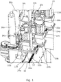
- Fig. 1 shows a close up view of a cast-on-strap machine unloading apparatus 10.
- Figs. 3 and 4 show that the apparatus 10 comprises six units 20a, 20b, 20c, 20d, 20e, and 20f, four of which are shown in the close-up view in Fig. 1 .
- Units 20a, 20c and 20e are the same, and units 20b, 20d and 20f are the same.
- the overall design of adjacent units differs slightly in order for the components to interleave along a rack, as will be described in more detail below, but the components and functionality are the exactly same, and so only one unit will be described in detail here.
- Fig. 2 shows unit 20a in more detail.
- Unit 20a comprises a rotary drive mechanism 22a and a pinion 24a.
- the rotary drive mechanism 22a and the pinion 24a are co-axial.
- the rotary drive mechanism 22a is in the form of a servo motor, and the pinion 24a is a toothed wheel-shaped gear.
- the pinion 24a is driveable by the servo motor 22a.
- the unloading apparatus 10 also comprises an elongate rack 12.
- the rack 12 comprises teeth 14 extending along a first side 12a and an opposing second side 12b.
- the units 20a-f are mounted adjacent to each other along the rack 12. Adjacent pinions 24a - f mesh with opposing sides of the rack 12.
- adjacent pinions 24a - d mesh with opposite sides 12a, 12b of the rack 12. That is, pinions 24a and 24c form part of a first array and mesh with the first side 12a of the rack 12, whereas pinions 24b and 24d form part of a second array and mesh with the second side 12b of the rack 12.
- pinions 24a - f form part of a first array and mesh with the first side 12a of the rack 12
- pinions 24b and 24d form part of a second array and mesh with the second side 12b of the rack 12.
- servo motors 22a and 22c are located on the first side 12a of the rack, and servo motors 22b and 22d are located on the second side 12b of the rack 12.
- the units comprising servo motors 22a and 22c are interleaved with the units comprising servo motors 22b and 22d.
- adjacent interleaved units, such as 20a and 20b are separated by a gap. The width of this gap can be less than the width of each servo motor.
- each unit 20a - f is defined as the axis of the unit perpendicular to the rack.
- Each servo motor 22a -f has a width of around 63 mm, which is the smallest size of standard motor which can interface to an Allen Bradley (RTM) servo drive.
- RTM Allen Bradley
- the minimum distance between the centrelines of adjacent units is at least 63 mm. This places a lower limit on the size of battery plate groups that can be processed by the unloading apparatus.
- the distance between the centrelines of adjacent interleaved units 20a - f can be much closer together.
- the distance between the centrelines of each unit can be at least 50% of the width of the rotary drive mechanism.
- the distance between adjacent centrelines is at least 50 mm.
- the distance between the centrelines of adjacent interleaved units 20a - f can be as little as 31.5 mm, thus allowing the apparatus 10 to process even smaller sized groups of battery plates, and produce even smaller batteries.
- each unit 20a - f also comprises an actuator 30a - f and a mechanical gripper 32a - f.
- Each actuator 30a - f is co-axial with its respective gripper 32a - f.
- Each gripper 32a - f is moveable between an open and closed position by its respective actuator 30a - f.
- Each actuator 30a - f and gripper mechanism 32a - f is located on the second side 12b of the rack 12. Placing the gripper mechanisms 32a - f on the same side of the rack makes it easier for the gripper mechanisms 32a - f to pick up a group of battery plates output from the cast-on-strap machine, and transfer them into a battery container.
- each gripper mechanism 32a - f can be configured to transfer its group of battery plates directly into an appropriate cell within the battery container.
- the apparatus 10 comprises a control module (not shown) which controls the operation of the unloading apparatus 10.
- Each servo motor 22a - f is located within an enclosure along with a position control mechanism 26a - f, in the form of an absolute encoder.
- Each absolute encoder 26a - f is located above its respective servo motor 22a - f, and is configured to detect the position of its respective unit 20a - f along the rack 12.
- groups of battery plates are processed by the cast-on-strap machine, and then delivered to the output section of the machine.
- the control module then receives a signal to indicate that there are groups of battery plates at the output from the cast-on-strap machine which need to be transferred into a battery container.
- the dimensions and structural information of the battery container is pre-programmed into the control module by an operator before the unloading apparatus 10 is operated.
- the control module then instructs each servo motor 22a - f to move its respective unit 20a- f along the length of the rack 12, so that its respective mechanical gripper 32a - f can pick up the groups of battery plates from the output from the cast-on-strap machine.
- the operation of each servo motor 22a - f causes rotation of its respective pinion 24a - f to be converted into linear motion of its respective unit along the rack 12.
- each actuator 30a - f is instructed to move the gripper mechanism 32a - f from the open to the closed position, so that each gripper mechanism 32a - f clamps and picks-up a group of battery plates.
- the control module can then calculate the required distance between the centrelines of each unit 20a - f. For example, if each cell within the container is 50 mm in width (that is, the centre points of adjacent cells are 50 mm apart), then the centrelines of adjacent units will need to be 50 mm apart.
- the control module also determines the required position of each unit 20a - f along the rack 12, based on the location of the battery container with respect to the rack 12. It is important that the units are placed at the correct location along the rack 12 and at the correct distance from each other, so that the gripper mechanisms 32a - f can accurately and precisely transfer the groups of battery plates into the correct cell.
- the control module instructs each servo motor 22a - f to move its respective unit 20a - f along the length of the rack 12 until its respective absolute encoder detects that the required position has been reached, both with respect to the rack 12 and adjacent units 20a - f.
- Each gripper mechanism 32a - f is now located above the appropriate cell of the battery container.
- the control module then instructs each actuator 30a - f to move the gripper mechanism 32a -f from the closed to the open position, so that each gripper mechanism 32a - f releases its respective group of battery plates into the appropriate cell of the battery container.
Landscapes
- Engineering & Computer Science (AREA)
- Manufacturing & Machinery (AREA)
- Mechanical Engineering (AREA)
- Chemical & Material Sciences (AREA)
- Chemical Kinetics & Catalysis (AREA)
- Electrochemistry (AREA)
- General Chemical & Material Sciences (AREA)
- Specific Conveyance Elements (AREA)
- Battery Mounting, Suspending (AREA)
- Basic Packing Technique (AREA)
Applications Claiming Priority (1)
| Application Number | Priority Date | Filing Date | Title |
|---|---|---|---|
| GB1911949.4A GB2586483B (en) | 2019-08-20 | 2019-08-20 | Unloading apparatus |
Publications (4)
| Publication Number | Publication Date |
|---|---|
| EP3783712A1 true EP3783712A1 (de) | 2021-02-24 |
| EP3783712C0 EP3783712C0 (de) | 2024-03-13 |
| EP3783712B1 EP3783712B1 (de) | 2024-03-13 |
| EP3783712B8 EP3783712B8 (de) | 2024-04-24 |
Family
ID=68099606
Family Applications (1)
| Application Number | Title | Priority Date | Filing Date |
|---|---|---|---|
| EP20189696.6A Active EP3783712B8 (de) | 2019-08-20 | 2020-08-05 | Entladevorrichtung |
Country Status (5)
| Country | Link |
|---|---|
| US (1) | US11597611B2 (de) |
| EP (1) | EP3783712B8 (de) |
| ES (1) | ES2980446T3 (de) |
| GB (1) | GB2586483B (de) |
| PL (1) | PL3783712T3 (de) |
Cited By (2)
| Publication number | Priority date | Publication date | Assignee | Title |
|---|---|---|---|---|
| CN113734786A (zh) * | 2021-09-22 | 2021-12-03 | 深圳市大成精密设备股份有限公司 | 一种电池夹取装置及其工作方法 |
| EP4583221A2 (de) | 2024-01-03 | 2025-07-09 | TBS Engineering Limited | Batterieplattenhandhabungsvorrichtung und -verfahren |
Families Citing this family (6)
| Publication number | Priority date | Publication date | Assignee | Title |
|---|---|---|---|---|
| IT202000008080A1 (it) * | 2020-04-16 | 2021-10-16 | A C M I Spa | Testa di manipolazione per oggetti |
| CN113955484A (zh) * | 2021-10-22 | 2022-01-21 | 苏州德睿联自动化科技有限公司 | 一种光伏领域电池串移栽搬运机械手 |
| CN114132749A (zh) * | 2022-01-10 | 2022-03-04 | 广东白云学院 | 电芯上下料系统 |
| CN114772264A (zh) * | 2022-04-29 | 2022-07-22 | 永康中奥自动化科技有限公司 | 一种带取放机械手的保温杯加工液压拉伸整形设备 |
| CN115383742A (zh) * | 2022-08-16 | 2022-11-25 | 江苏烽禾升智能科技有限公司 | 一种基于ctp的电芯柔性夹取摆放装置 |
| CN116986268A (zh) * | 2023-05-22 | 2023-11-03 | 深圳市益鸿智能科技有限公司 | 智能缩距机构 |
Citations (3)
| Publication number | Priority date | Publication date | Assignee | Title |
|---|---|---|---|---|
| JPH03214560A (ja) * | 1990-01-16 | 1991-09-19 | Furukawa Battery Co Ltd:The | 鉛蓄電池用cos式鋳型装置、極板群列の電槽への組込み法並に組込み装置 |
| US5459922A (en) * | 1993-05-29 | 1995-10-24 | Tbs Engineering Limited | Loading apparatus and methods |
| US20070266553A1 (en) * | 2004-11-22 | 2007-11-22 | Gd Technologies Maschinebau Gmbh | Process And System For Joining Battery Plates To Form Packs And For Inserting These Packs Into Cassettes |
Family Cites Families (14)
| Publication number | Priority date | Publication date | Assignee | Title |
|---|---|---|---|---|
| US4168772A (en) * | 1974-10-01 | 1979-09-25 | General Battery Corporation | Apparatus and method for stacking battery plates and separators |
| US4534401A (en) * | 1982-05-21 | 1985-08-13 | Gnb Batteries Inc. | Apparatus and method for casting straps on battery cell elements |
| US4583286A (en) * | 1983-03-28 | 1986-04-22 | Gnb Batteries Inc. | Apparatus and method for processing and transferring battery cell elements |
| GB8700906D0 (en) * | 1987-01-16 | 1987-02-18 | Tbs Eng Cheltenham | Handling apparatus |
| US4982482A (en) * | 1989-02-24 | 1991-01-08 | Caltec International, Inc. | Method for the manufacture of lead-acid batteries and an associated apparatus and associated lead-acid battery |
| US5079111A (en) * | 1989-02-24 | 1992-01-07 | Caltec International, Inc. | Method for the manufacture of lead-acid batteries and an associated apparatus and associated lead-acid battery |
| US4998340A (en) * | 1989-02-24 | 1991-03-12 | Cal-Tec International, Inc. | Method for the manufacture of lead-acid batteries and an associated apparatus and associated lead-acid battery |
| US5044067A (en) * | 1989-02-24 | 1991-09-03 | Caltec International, Inc. | Method for the manufacture of lead acid batteries and an associated apparatus and associated lead-acid battery |
| GB9610441D0 (en) * | 1996-05-17 | 1996-07-24 | Tbs Eng Ltd | Loading apparatus |
| TWI496732B (zh) * | 2009-07-31 | 2015-08-21 | 村田機械股份有限公司 | 供工具利用之緩衝儲存和運輸裝置 |
| WO2012118306A2 (ko) * | 2011-02-28 | 2012-09-07 | Kang Tae In | 배터리 터미널 플레이트의 제조장치 및 제조방법 |
| US9397331B2 (en) * | 2012-09-24 | 2016-07-19 | Wirtz Manufacturing Company, Inc. | Battery grid pasting machine and system |
| US10446877B2 (en) * | 2013-08-19 | 2019-10-15 | Sasit Industrietechnik Gmbh | Installation for producing both AGM and wet-cell batteries for passenger-car and commercial-vehicle battery types |
| KR20180083484A (ko) * | 2017-01-13 | 2018-07-23 | (주)홍익 하이엠 | 컨베이어 상의 극판집속체 이송장치 |
-
2019
- 2019-08-20 GB GB1911949.4A patent/GB2586483B/en active Active
-
2020
- 2020-08-04 US US16/984,703 patent/US11597611B2/en active Active
- 2020-08-05 PL PL20189696.6T patent/PL3783712T3/pl unknown
- 2020-08-05 EP EP20189696.6A patent/EP3783712B8/de active Active
- 2020-08-05 ES ES20189696T patent/ES2980446T3/es active Active
Patent Citations (3)
| Publication number | Priority date | Publication date | Assignee | Title |
|---|---|---|---|---|
| JPH03214560A (ja) * | 1990-01-16 | 1991-09-19 | Furukawa Battery Co Ltd:The | 鉛蓄電池用cos式鋳型装置、極板群列の電槽への組込み法並に組込み装置 |
| US5459922A (en) * | 1993-05-29 | 1995-10-24 | Tbs Engineering Limited | Loading apparatus and methods |
| US20070266553A1 (en) * | 2004-11-22 | 2007-11-22 | Gd Technologies Maschinebau Gmbh | Process And System For Joining Battery Plates To Form Packs And For Inserting These Packs Into Cassettes |
Cited By (3)
| Publication number | Priority date | Publication date | Assignee | Title |
|---|---|---|---|---|
| CN113734786A (zh) * | 2021-09-22 | 2021-12-03 | 深圳市大成精密设备股份有限公司 | 一种电池夹取装置及其工作方法 |
| EP4583221A2 (de) | 2024-01-03 | 2025-07-09 | TBS Engineering Limited | Batterieplattenhandhabungsvorrichtung und -verfahren |
| EP4583221A3 (de) * | 2024-01-03 | 2025-08-13 | TBS Engineering Limited | Batterieplattenhandhabungsvorrichtung und -verfahren |
Also Published As
| Publication number | Publication date |
|---|---|
| EP3783712C0 (de) | 2024-03-13 |
| US11597611B2 (en) | 2023-03-07 |
| GB2586483A (en) | 2021-02-24 |
| US20210053771A1 (en) | 2021-02-25 |
| EP3783712B1 (de) | 2024-03-13 |
| GB2586483B (en) | 2021-09-08 |
| ES2980446T3 (es) | 2024-10-01 |
| PL3783712T3 (pl) | 2024-07-15 |
| EP3783712B8 (de) | 2024-04-24 |
| GB201911949D0 (en) | 2019-10-02 |
Similar Documents
| Publication | Publication Date | Title |
|---|---|---|
| EP3783712A1 (de) | Entladevorrichtung | |
| US4509252A (en) | Method and apparatus for assembling battery components | |
| US20250278075A1 (en) | Product changeover method and system for production line | |
| CN211729156U (zh) | 一种上下料的机械手 | |
| CN112794061A (zh) | 一种自动上料装置 | |
| EP4603427A1 (de) | Klemmanordnung, greifvorrichtung, batterieherstellungslinie, klemmverfahren und übertragungsverfahren | |
| CN1262040C (zh) | 矩形锂离子动力电池极片叠垛机 | |
| JP5656804B2 (ja) | 組立ロボット装置 | |
| US5802967A (en) | Arrangement for transferring workpieces through a succession of machining stations | |
| KR102525643B1 (ko) | 배터리셀 활성화용 가압/가열장치 | |
| EP4583221A2 (de) | Batterieplattenhandhabungsvorrichtung und -verfahren | |
| US3199653A (en) | Article transfer and stacking device for power-driven conveyors | |
| CN218808905U (zh) | 一种复合物流分发机器人及系统 | |
| CN219859252U (zh) | 一种电芯批量上下料设备 | |
| US6834787B2 (en) | Feeding devices for taped electric components | |
| CN117427895A (zh) | 一种叠片电芯在线检测设备及检测方法 | |
| CN210619508U (zh) | 一种移料装置 | |
| CN221473978U (zh) | 供料系统及电池顶盖焊接设备 | |
| CN223280116U (zh) | 一种自动化电芯理料码垛装置 | |
| CN213230158U (zh) | 一种兼容同步带的叠片极片搬运驱动模组 | |
| JP6557053B2 (ja) | 移送装置 | |
| CN223338846U (zh) | 保险盒的保险片组装设备 | |
| CN223990213U (zh) | 一种推钞机构 | |
| US20250372724A1 (en) | Method for producing accumulators and corresponding stacking device for producing accumulators | |
| CN109911564A (zh) | 一种汽车电池传感器自动上料设备 |
Legal Events
| Date | Code | Title | Description |
|---|---|---|---|
| PUAI | Public reference made under article 153(3) epc to a published international application that has entered the european phase |
Free format text: ORIGINAL CODE: 0009012 |
|
| STAA | Information on the status of an ep patent application or granted ep patent |
Free format text: STATUS: REQUEST FOR EXAMINATION WAS MADE |
|
| 17P | Request for examination filed |
Effective date: 20200805 |
|
| AK | Designated contracting states |
Kind code of ref document: A1 Designated state(s): AL AT BE BG CH CY CZ DE DK EE ES FI FR GB GR HR HU IE IS IT LI LT LU LV MC MK MT NL NO PL PT RO RS SE SI SK SM TR |
|
| AX | Request for extension of the european patent |
Extension state: BA ME |
|
| GRAP | Despatch of communication of intention to grant a patent |
Free format text: ORIGINAL CODE: EPIDOSNIGR1 |
|
| STAA | Information on the status of an ep patent application or granted ep patent |
Free format text: STATUS: GRANT OF PATENT IS INTENDED |
|
| RIC1 | Information provided on ipc code assigned before grant |
Ipc: B65G 61/00 20060101ALI20231009BHEP Ipc: B65G 47/90 20060101ALI20231009BHEP Ipc: B65G 49/06 20060101ALI20231009BHEP Ipc: H01M 10/14 20060101ALI20231009BHEP Ipc: H01M 10/04 20060101AFI20231009BHEP |
|
| INTG | Intention to grant announced |
Effective date: 20231027 |
|
| GRAS | Grant fee paid |
Free format text: ORIGINAL CODE: EPIDOSNIGR3 |
|
| GRAA | (expected) grant |
Free format text: ORIGINAL CODE: 0009210 |
|
| STAA | Information on the status of an ep patent application or granted ep patent |
Free format text: STATUS: THE PATENT HAS BEEN GRANTED |
|
| AK | Designated contracting states |
Kind code of ref document: B1 Designated state(s): AL AT BE BG CH CY CZ DE DK EE ES FI FR GB GR HR HU IE IS IT LI LT LU LV MC MK MT NL NO PL PT RO RS SE SI SK SM TR |
|
| REG | Reference to a national code |
Ref country code: GB Ref legal event code: FG4D |
|
| REG | Reference to a national code |
Ref country code: CH Ref legal event code: EP |
|
| REG | Reference to a national code |
Ref country code: CH Ref legal event code: PK Free format text: BERICHTIGUNG B8 Ref country code: DE Ref legal event code: R096 Ref document number: 602020027076 Country of ref document: DE |
|
| RBV | Designated contracting states (corrected) |
Designated state(s): AL AT BE BG CH CY CZ DE DK EE ES FI FR GR HR HU IE IS IT LI LT LU LV MC MK MT NL NO PL PT RO RS SE SI SK SM TR |
|
| REG | Reference to a national code |
Ref country code: IE Ref legal event code: FG4D |
|
| REG | Reference to a national code |
Ref country code: CH Ref legal event code: PK Free format text: BERICHTIGUNG B8 Ref country code: CH Ref legal event code: PK Free format text: DIE PUBLIKATION VOM 27.03.2024 WURDE AM 24.04.2024 IRRTUEMLICHERWEISE ERNEUT PUBLIZIERT. LA PUBLICATION DU 27.03.2024 A ETE REPUBLIEE PAR ERREUR LE 24.04.2024. LA PUBBLICAZIONE DEL 27.03.2024 E STATA ERRONEAMENTE RIPUBBLICATA IL 24.04.2024. |
|
| U01 | Request for unitary effect filed |
Effective date: 20240412 |
|
| U07 | Unitary effect registered |
Designated state(s): AT BE BG DE DK EE FI FR IT LT LU LV MT NL PT SE SI Effective date: 20240508 |
|
| PG25 | Lapsed in a contracting state [announced via postgrant information from national office to epo] |
Ref country code: GR Free format text: LAPSE BECAUSE OF FAILURE TO SUBMIT A TRANSLATION OF THE DESCRIPTION OR TO PAY THE FEE WITHIN THE PRESCRIBED TIME-LIMIT Effective date: 20240614 |
|
| PG25 | Lapsed in a contracting state [announced via postgrant information from national office to epo] |
Ref country code: RS Free format text: LAPSE BECAUSE OF FAILURE TO SUBMIT A TRANSLATION OF THE DESCRIPTION OR TO PAY THE FEE WITHIN THE PRESCRIBED TIME-LIMIT Effective date: 20240613 Ref country code: HR Free format text: LAPSE BECAUSE OF FAILURE TO SUBMIT A TRANSLATION OF THE DESCRIPTION OR TO PAY THE FEE WITHIN THE PRESCRIBED TIME-LIMIT Effective date: 20240313 |
|
| PG25 | Lapsed in a contracting state [announced via postgrant information from national office to epo] |
Ref country code: RS Free format text: LAPSE BECAUSE OF FAILURE TO SUBMIT A TRANSLATION OF THE DESCRIPTION OR TO PAY THE FEE WITHIN THE PRESCRIBED TIME-LIMIT Effective date: 20240613 Ref country code: NO Free format text: LAPSE BECAUSE OF FAILURE TO SUBMIT A TRANSLATION OF THE DESCRIPTION OR TO PAY THE FEE WITHIN THE PRESCRIBED TIME-LIMIT Effective date: 20240613 Ref country code: HR Free format text: LAPSE BECAUSE OF FAILURE TO SUBMIT A TRANSLATION OF THE DESCRIPTION OR TO PAY THE FEE WITHIN THE PRESCRIBED TIME-LIMIT Effective date: 20240313 Ref country code: GR Free format text: LAPSE BECAUSE OF FAILURE TO SUBMIT A TRANSLATION OF THE DESCRIPTION OR TO PAY THE FEE WITHIN THE PRESCRIBED TIME-LIMIT Effective date: 20240614 |
|
| U20 | Renewal fee for the european patent with unitary effect paid |
Year of fee payment: 5 Effective date: 20240717 |
|
| REG | Reference to a national code |
Ref country code: ES Ref legal event code: FG2A Ref document number: 2980446 Country of ref document: ES Kind code of ref document: T3 Effective date: 20241001 |
|
| PG25 | Lapsed in a contracting state [announced via postgrant information from national office to epo] |
Ref country code: IS Free format text: LAPSE BECAUSE OF FAILURE TO SUBMIT A TRANSLATION OF THE DESCRIPTION OR TO PAY THE FEE WITHIN THE PRESCRIBED TIME-LIMIT Effective date: 20240713 |
|
| PG25 | Lapsed in a contracting state [announced via postgrant information from national office to epo] |
Ref country code: SM Free format text: LAPSE BECAUSE OF FAILURE TO SUBMIT A TRANSLATION OF THE DESCRIPTION OR TO PAY THE FEE WITHIN THE PRESCRIBED TIME-LIMIT Effective date: 20240313 |
|
| PG25 | Lapsed in a contracting state [announced via postgrant information from national office to epo] |
Ref country code: CZ Free format text: LAPSE BECAUSE OF FAILURE TO SUBMIT A TRANSLATION OF THE DESCRIPTION OR TO PAY THE FEE WITHIN THE PRESCRIBED TIME-LIMIT Effective date: 20240313 |
|
| PG25 | Lapsed in a contracting state [announced via postgrant information from national office to epo] |
Ref country code: SK Free format text: LAPSE BECAUSE OF FAILURE TO SUBMIT A TRANSLATION OF THE DESCRIPTION OR TO PAY THE FEE WITHIN THE PRESCRIBED TIME-LIMIT Effective date: 20240313 |
|
| PG25 | Lapsed in a contracting state [announced via postgrant information from national office to epo] |
Ref country code: SM Free format text: LAPSE BECAUSE OF FAILURE TO SUBMIT A TRANSLATION OF THE DESCRIPTION OR TO PAY THE FEE WITHIN THE PRESCRIBED TIME-LIMIT Effective date: 20240313 Ref country code: SK Free format text: LAPSE BECAUSE OF FAILURE TO SUBMIT A TRANSLATION OF THE DESCRIPTION OR TO PAY THE FEE WITHIN THE PRESCRIBED TIME-LIMIT Effective date: 20240313 Ref country code: RO Free format text: LAPSE BECAUSE OF FAILURE TO SUBMIT A TRANSLATION OF THE DESCRIPTION OR TO PAY THE FEE WITHIN THE PRESCRIBED TIME-LIMIT Effective date: 20240313 Ref country code: IS Free format text: LAPSE BECAUSE OF FAILURE TO SUBMIT A TRANSLATION OF THE DESCRIPTION OR TO PAY THE FEE WITHIN THE PRESCRIBED TIME-LIMIT Effective date: 20240713 Ref country code: CZ Free format text: LAPSE BECAUSE OF FAILURE TO SUBMIT A TRANSLATION OF THE DESCRIPTION OR TO PAY THE FEE WITHIN THE PRESCRIBED TIME-LIMIT Effective date: 20240313 |
|
| REG | Reference to a national code |
Ref country code: DE Ref legal event code: R097 Ref document number: 602020027076 Country of ref document: DE |
|
| PLBE | No opposition filed within time limit |
Free format text: ORIGINAL CODE: 0009261 |
|
| STAA | Information on the status of an ep patent application or granted ep patent |
Free format text: STATUS: NO OPPOSITION FILED WITHIN TIME LIMIT |
|
| 26N | No opposition filed |
Effective date: 20241216 |
|
| REG | Reference to a national code |
Ref country code: CH Ref legal event code: PL |
|
| PG25 | Lapsed in a contracting state [announced via postgrant information from national office to epo] |
Ref country code: MC Free format text: LAPSE BECAUSE OF FAILURE TO SUBMIT A TRANSLATION OF THE DESCRIPTION OR TO PAY THE FEE WITHIN THE PRESCRIBED TIME-LIMIT Effective date: 20240313 Ref country code: CH Free format text: LAPSE BECAUSE OF NON-PAYMENT OF DUE FEES Effective date: 20240831 |
|
| PGFP | Annual fee paid to national office [announced via postgrant information from national office to epo] |
Ref country code: PL Payment date: 20250612 Year of fee payment: 6 |
|
| PGFP | Annual fee paid to national office [announced via postgrant information from national office to epo] |
Ref country code: TR Payment date: 20250611 Year of fee payment: 6 |
|
| PG25 | Lapsed in a contracting state [announced via postgrant information from national office to epo] |
Ref country code: IE Free format text: LAPSE BECAUSE OF NON-PAYMENT OF DUE FEES Effective date: 20240805 |
|
| U20 | Renewal fee for the european patent with unitary effect paid |
Year of fee payment: 6 Effective date: 20250718 |
|
| PGFP | Annual fee paid to national office [announced via postgrant information from national office to epo] |
Ref country code: ES Payment date: 20250903 Year of fee payment: 6 |
|
| PG25 | Lapsed in a contracting state [announced via postgrant information from national office to epo] |
Ref country code: CY Free format text: LAPSE BECAUSE OF FAILURE TO SUBMIT A TRANSLATION OF THE DESCRIPTION OR TO PAY THE FEE WITHIN THE PRESCRIBED TIME-LIMIT; INVALID AB INITIO Effective date: 20200805 |
|
| PG25 | Lapsed in a contracting state [announced via postgrant information from national office to epo] |
Ref country code: HU Free format text: LAPSE BECAUSE OF FAILURE TO SUBMIT A TRANSLATION OF THE DESCRIPTION OR TO PAY THE FEE WITHIN THE PRESCRIBED TIME-LIMIT; INVALID AB INITIO Effective date: 20200805 |