EP3785502B1 - Provisioning data center server cooling equipment - Google Patents
Provisioning data center server cooling equipment Download PDFInfo
- Publication number
- EP3785502B1 EP3785502B1 EP19752835.9A EP19752835A EP3785502B1 EP 3785502 B1 EP3785502 B1 EP 3785502B1 EP 19752835 A EP19752835 A EP 19752835A EP 3785502 B1 EP3785502 B1 EP 3785502B1
- Authority
- EP
- European Patent Office
- Prior art keywords
- liquid
- data center
- cooling
- cooling apparatus
- outlet
- Prior art date
- Legal status (The legal status is an assumption and is not a legal conclusion. Google has not performed a legal analysis and makes no representation as to the accuracy of the status listed.)
- Active
Links
Images


Classifications
-
- H—ELECTRICITY
- H05—ELECTRIC TECHNIQUES NOT OTHERWISE PROVIDED FOR
- H05K—PRINTED CIRCUITS; CASINGS OR CONSTRUCTIONAL DETAILS OF ELECTRIC APPARATUS; MANUFACTURE OF ASSEMBLAGES OF ELECTRICAL COMPONENTS
- H05K7/00—Constructional details common to different types of electric apparatus
- H05K7/20—Modifications to facilitate cooling, ventilating, or heating
- H05K7/20218—Modifications to facilitate cooling, ventilating, or heating using a liquid coolant without phase change in electronic enclosures
- H05K7/20272—Accessories for moving fluid, for expanding fluid, for connecting fluid conduits, for distributing fluid, for removing gas or for preventing leakage, e.g. pumps, tanks or manifolds
-
- H—ELECTRICITY
- H05—ELECTRIC TECHNIQUES NOT OTHERWISE PROVIDED FOR
- H05K—PRINTED CIRCUITS; CASINGS OR CONSTRUCTIONAL DETAILS OF ELECTRIC APPARATUS; MANUFACTURE OF ASSEMBLAGES OF ELECTRICAL COMPONENTS
- H05K7/00—Constructional details common to different types of electric apparatus
- H05K7/20—Modifications to facilitate cooling, ventilating, or heating
- H05K7/20709—Modifications to facilitate cooling, ventilating, or heating for server racks or cabinets; for data centers, e.g. 19-inch computer racks
- H05K7/20763—Liquid cooling without phase change
- H05K7/20781—Liquid cooling without phase change within cabinets for removing heat from server blades
-
- H—ELECTRICITY
- H05—ELECTRIC TECHNIQUES NOT OTHERWISE PROVIDED FOR
- H05K—PRINTED CIRCUITS; CASINGS OR CONSTRUCTIONAL DETAILS OF ELECTRIC APPARATUS; MANUFACTURE OF ASSEMBLAGES OF ELECTRICAL COMPONENTS
- H05K7/00—Constructional details common to different types of electric apparatus
- H05K7/20—Modifications to facilitate cooling, ventilating, or heating
- H05K7/20009—Modifications to facilitate cooling, ventilating, or heating using a gaseous coolant in electronic enclosures
- H05K7/20136—Forced ventilation, e.g. by fans
- H05K7/20145—Means for directing air flow, e.g. ducts, deflectors, plenum or guides
-
- H—ELECTRICITY
- H05—ELECTRIC TECHNIQUES NOT OTHERWISE PROVIDED FOR
- H05K—PRINTED CIRCUITS; CASINGS OR CONSTRUCTIONAL DETAILS OF ELECTRIC APPARATUS; MANUFACTURE OF ASSEMBLAGES OF ELECTRICAL COMPONENTS
- H05K7/00—Constructional details common to different types of electric apparatus
- H05K7/20—Modifications to facilitate cooling, ventilating, or heating
- H05K7/20218—Modifications to facilitate cooling, ventilating, or heating using a liquid coolant without phase change in electronic enclosures
- H05K7/20281—Thermal management, e.g. liquid flow control
-
- H—ELECTRICITY
- H05—ELECTRIC TECHNIQUES NOT OTHERWISE PROVIDED FOR
- H05K—PRINTED CIRCUITS; CASINGS OR CONSTRUCTIONAL DETAILS OF ELECTRIC APPARATUS; MANUFACTURE OF ASSEMBLAGES OF ELECTRICAL COMPONENTS
- H05K7/00—Constructional details common to different types of electric apparatus
- H05K7/20—Modifications to facilitate cooling, ventilating, or heating
- H05K7/20709—Modifications to facilitate cooling, ventilating, or heating for server racks or cabinets; for data centers, e.g. 19-inch computer racks
- H05K7/20718—Forced ventilation of a gaseous coolant
- H05K7/20736—Forced ventilation of a gaseous coolant within cabinets for removing heat from server blades
-
- H—ELECTRICITY
- H05—ELECTRIC TECHNIQUES NOT OTHERWISE PROVIDED FOR
- H05K—PRINTED CIRCUITS; CASINGS OR CONSTRUCTIONAL DETAILS OF ELECTRIC APPARATUS; MANUFACTURE OF ASSEMBLAGES OF ELECTRICAL COMPONENTS
- H05K7/00—Constructional details common to different types of electric apparatus
- H05K7/20—Modifications to facilitate cooling, ventilating, or heating
- H05K7/20709—Modifications to facilitate cooling, ventilating, or heating for server racks or cabinets; for data centers, e.g. 19-inch computer racks
- H05K7/20836—Thermal management, e.g. server temperature control
-
- Y—GENERAL TAGGING OF NEW TECHNOLOGICAL DEVELOPMENTS; GENERAL TAGGING OF CROSS-SECTIONAL TECHNOLOGIES SPANNING OVER SEVERAL SECTIONS OF THE IPC; TECHNICAL SUBJECTS COVERED BY FORMER USPC CROSS-REFERENCE ART COLLECTIONS [XRACs] AND DIGESTS
- Y02—TECHNOLOGIES OR APPLICATIONS FOR MITIGATION OR ADAPTATION AGAINST CLIMATE CHANGE
- Y02D—CLIMATE CHANGE MITIGATION TECHNOLOGIES IN INFORMATION AND COMMUNICATION TECHNOLOGIES [ICT], I.E. INFORMATION AND COMMUNICATION TECHNOLOGIES AIMING AT THE REDUCTION OF THEIR OWN ENERGY USE
- Y02D10/00—Energy efficient computing, e.g. low power processors, power management or thermal management
Definitions
- This document relates to systems and methods for provisioning data center cooling equipment, such as liquid cooling apparatus for computer server racks and related equipment in computer data centers.
- US 2012/0180979 A1 discloses a leak-tolerant liquid cooling system with a backup air-cooling system for computers.
- the system may use a vacuum pump and a liquid pump and/or an air compressor in combination to provide negative fluid pressure so that liquid does not leak out of the system near electrical components.
- the system can use a single vacuum pump and a valve assembly to circulate coolant.
- the system distributes flow and pressure with a series of pressure regulating valves so that an array of computers can be serviced by a single cooling system.
- the system provides both air and liquid cooling so that if the liquid cooling system does not provide adequate cooling, the air cooling system will be automatically activated. The heat may be removed from the building efficiently with a cooling tower.
- a data center liquid cooling apparatus provisioning system includes a housing that defines a volume that is at least partially accessible through one or more openings of the housing, a cooling liquid flow circuit at least partially enclosed within the volume, and a control system communicably coupled to the cooling liquid flow circuit.
- the cooling liquid flow circuit includes a cooling liquid supply tank configured to store a volume of a cooling liquid; a pump coupled to the cooling liquid supply tank and coupled to an outlet configured to connect to a data center liquid cooling apparatus; a cooling liquid waste tank coupled to an inlet configured to connect to the data center liquid cooling apparatus; and a sensor in fluid communication with the cooling liquid flow circuit and configured to sense a liquid fill amount of the data center liquid cooling apparatus.
- the control system is configured to perform operations including operating the pump to circulate a volume of the cooling liquid from the cooling liquid supply tank to the data center liquid cooling apparatus sufficient to at least fill the data center liquid cooling apparatus; and based on the sensor indicating that the fill amount of the data center liquid cooling apparatus is above a threshold value, stopping operation of the pump, and a data center liquid cooling apparatus evacuation assembly fluidly coupled to the cooling liquid flow circuit, the data center liquid cooling apparatus evacuation assembly comprising:an air compressor;a pressurized air reservoir fluidly connected to the air compressor;an air outlet fluidly connected to the outlet of the cooling liquid flow circuit;and an air valve fluidly connected between the pressurized air reservoir and the air outlet,wherein an evacuation or decommissioning operation is configured such that said operation circulates a pressurized gas from a compressed gas evacuation sub-system to the liquid cooling apparatus.
- the cooling liquid flow circuit further includes at least one liquid filter positioned between the cooling liquid supply tank and the outlet.
- the data center liquid cooling apparatus includes a liquid cold plate or evaporator configured to thermally couple to one or more data center heat generating devices.
- the pump includes a peristaltic pump.
- the cooling liquid flow circuit further includes a first quick disconnect positioned at the outlet and a second quick disconnect positioned at the inlet.
- control system is configured to perform operations further including determining that the sensor indicates that the fill amount of the data center liquid cooling apparatus is below a threshold value; operating the pump to circulate at least a portion of the cooling liquid from the cooling liquid supply tank, through the data center liquid cooling apparatus, and into the cooling liquid waste tank; and based on the sensor indicating that the fill amount of the data center liquid cooling apparatus is above a threshold value, stopping operation of the pump.
- the senor includes a pressure sensor configured to measure a fluid pressure of the cooling liquid in at least one of the cooling liquid flow circuit or the data center cooling device.
- control system is configured to perform operations further including operating the pump to circulate the volume of the cooling liquid from the cooling liquid supply tank to the data center liquid cooling apparatus to evacuate at least a portion of a gas inside the data center liquid cooling apparatus into the cooling liquid waste tank.
- the cooling liquid flow circuit further includes one or more one-way check valves configured to permit a flow of the cooling liquid through the cooling liquid flow circuit in a single direction.
- a first check valve of the one or more check valves is positioned between a filter of the cooling liquid flow circuit and the inlet, and a second check valve of the one or more check valves is positioned between the inlet and the cooling liquid waste tank.
- the data center liquid cooling apparatus provisioning system further includes a data center liquid cooling apparatus evacuation assembly fluidly coupled to the cooling liquid flow circuit.
- the data center liquid cooling apparatus evacuation assembly includes an air compressor; a pressurized air reservoir fluidly connected to the air compressor; an air outlet fluidly connected to the outlet of the cooling liquid flow circuit; and an air valve fluidly connected between the pressurized air reservoir and the air outlet.
- control system is configured to perform operations further including operating the air compressor to circulate pressurized air into the pressurized air reservoir; operating the air valve to release pressurized air through the air outlet, through the outlet of the cooling liquid flow circuit, and into the data center liquid cooling apparatus.
- the cooling liquid waste tank is fluidly connected to the air outlet to receive a mixture of cooling liquid and pressurized air from the data center liquid cooling apparatus during flow of the released pressurized air.
- a method for provisioning a data center liquid cooling apparatus includes fluidly connecting a liquid inlet data center liquid cooling apparatus to an outlet of a data center liquid cooling apparatus provisioning system and fluidly connecting a liquid outlet of the data center liquid cooling apparatus to an inlet of the data center liquid cooling apparatus provisioning system.
- the data center liquid cooling apparatus provisioning system includes a cooling liquid supply tank, a pump coupled to the cooling liquid supply tank and coupled to the outlet, and a sensor in fluid communication with at least one of the inlet or the outlet.
- the method also includes operating the pump to circulate a volume of a cooling liquid from the cooling liquid supply tank to the data center liquid cooling apparatus sufficient to at least fill the data center liquid cooling apparatus and based on the sensor indicating that a fill amount of the data center liquid cooling apparatus is above a threshold value, stopping operation of the pump, and evacuating an amount of cooling liquid from the data center liquid cooling apparatus with an evacuation assembly of the data center liquid cooling apparatus provisioning system that is fluidly coupled to the outlet, the evacuation assembly comprising:an air compressor;a pressurized air reservoir fluidly connected to the air compressor;an air outlet fluidly connected to the outlet of the cooling liquid flow circuit; and an air valve fluidly connected between the pressurized air reservoir and the air outlet,wherein evacuating includes circulating a pressurized gas from a compressed gas evacuation sub-system to the liquid cooling apparatus.
- An aspect combinable with the example implementation further includes circulating the volume of the cooling liquid through at least one liquid filter prior to circulating the volume of the cooling liquid to the data center liquid cooling apparatus.
- the data center liquid cooling apparatus includes a liquid cold plate or evaporator configured to thermally couple to one or more data center heat generating devices.
- the pump includes a peristaltic pump.
- the data center liquid cooling apparatus provisioning system further includes a first quick disconnect positioned at the outlet and a second quick disconnect positioned at the inlet.
- An aspect combinable with any of the previous aspects further includes determining that the sensor indicates that the fill amount of the data center liquid cooling apparatus is below a threshold value; operating the pump to circulate at least a portion of the cooling liquid from the cooling liquid supply tank, through the data center liquid cooling apparatus, and into a cooling liquid waste tank of the data center liquid cooling apparatus provisioning system; and based on the sensor indicating that the fill amount of the data center liquid cooling apparatus is above a threshold value, stopping operation of the pump.
- the senor includes a pressure sensor.
- An aspect combinable with any of the previous aspects further includes measuring, with the sensor, a fluid pressure of the cooling liquid in at least one of the cooling liquid flow circuit or the data center cooling device; and determining the fill amount based on the measured fluid pressure.
- An aspect combinable with any of the previous aspects further includes operating the pump to circulate the volume of the cooling liquid from the cooling liquid supply tank to the data center liquid cooling apparatus to evacuate at least a portion of a gas inside the data center liquid cooling apparatus into the cooling liquid waste tank.
- the data center liquid cooling apparatus provisioning system further includes one or more one-way check valves configured to permit a flow of the cooling liquid in a single direction.
- a first check valve of the one or more check valves is positioned between a filter of the data center liquid cooling apparatus provisioning system and the inlet, and a second check valve of the one or more check valves is positioned between the inlet and a cooling liquid waste tank.
- the method further includes evacuating an amount of cooling liquid from the data center liquid cooling apparatus with an evacuation assembly of the data center liquid cooling apparatus provisioning system that is fluidly coupled to the outlet.
- the evacuation assembly includes an air compressor; a pressurized air reservoir fluidly connected to the air compressor; an air outlet fluidly connected to the outlet of the cooling liquid flow circuit; and an air valve fluidly connected between the pressurized air reservoir and the air outlet.
- An aspect combinable with any of the previous aspects further includes operating the air compressor to circulate pressurized air into the pressurized air reservoir; and operating the air valve to release pressurized air through the air outlet, through the outlet of the cooling liquid flow circuit, and into the data center liquid cooling apparatus.
- a cooling liquid waste tank is fluidly connected to the air outlet to receive a mixture of cooling liquid and pressurized air from the data center liquid cooling apparatus during flow of the released pressurized air.
- a data center cooling equipment provisioning system may include one, some, or all of the following features.
- a data center cooling equipment provisioning system may provide for an efficient system and process for charging (e.g., with a cooling liquid) a server liquid cooling system (e.g., a cold plate, evaporator, and other related equipment) at various stages to mitigate risks typically involved with preparing such equipment for operation.
- a data center cooling equipment provisioning system may allow for such cooling equipment to be pre-charged and pressurized with liquid prior to installation, e.g., in a server rack or in a server tray assembly.
- a data center cooling equipment provisioning system may mitigate air entrainment resulting in a loss of heat transfer capability, and pump damage through cavitation.
- a data center cooling equipment provisioning system may provide for both charging and discharging the liquid cooling equipment, for example, during commissioning and decommissioning, respectively.
- a data center cooling equipment provisioning system may mitigate air entrainment in the cooling system that can result in unwetted areas of the internal pipes, manifolds, and couplings that are susceptible to corrosion and bio-growth, e.g., contamination.
- FIG. 1 illustrates an isometric view of an example implementation of a data center liquid cooling apparatus provisioning system 100 ("system 100").
- the system 100 may operate or be operated to provision one or more data center liquid cooling apparatus, e.g., prior to such apparatus being put into service to a data center to cool data center devices, such as server trays (and more specifically, heat-generating devices such as processors, memories, voltage regulators, and other devices mounted on motherboards of the server trays).
- data center liquid cooling apparatus such as server trays (and more specifically, heat-generating devices such as processors, memories, voltage regulators, and other devices mounted on motherboards of the server trays).
- such liquid cooling apparatus include cold plates or evaporators that are mounted in thermal communication with the heat generating devices (in the server trays) and utilize a flow of a cooling liquid (e.g., water, glycol, refrigerant) to remove heat from the server tray (e.g., with or without a phase change of the cooling liquid).
- a cooling liquid e.g., water, glycol, refrigerant
- the cooling liquid is circulated, e.g., at a particular flow rate and fluid pressure, to cool the server tray.
- the system 100 may be operated to provision many (e.g., tens, hundreds, thousands, tens of thousands) liquid cooling apparatus by pre-filling each apparatus with a particular amount of cooling liquid at a particular fluid pressure such that initiation of the typical operation of the liquid cooling apparatus is more efficient with fewer issues.
- the system 100 may reduce an amount of air in each liquid cooling apparatus (and the overall data center cooling system that includes many such apparatus as well as return and supply manifolds, pumps, and other liquid carrying conduits). By reducing such air, cavitation of the pumps in the overall data center cooling system may be reduced as well.
- provisioning the liquid cooling apparatus by the system 100 may also include decommissioning the liquid cooling apparatus by removing any remaining cooling liquid present in the apparatus subsequent to shutdown of the apparatus (e.g., for maintenance, cleaning, or otherwise).
- the system 100 includes a housing 102 (in this example, a cart, with the top shown as “invisible” in the figure so as to illustrate components therewithin) that is mounted on one or more casters 104 (or other form of rollers or wheels) and includes a volume 103 in which one or more components of the system 100 are at least partially enclosed.
- a housing 102 in this example, a cart, with the top shown as “invisible” in the figure so as to illustrate components therewithin
- casters 104 or other form of rollers or wheels
- a volume 103 in which one or more components of the system 100 are at least partially enclosed.
- one or more doors may be mounted on sides of the housing 102 to allow access to the volume 103.
- cooling liquid supply tank 108 is mounted within the volume 103 and can store a volume of cooling liquid to be provisioned to one or more liquid cooling apparatus.
- the volume of cooling liquid stored in the tank 108 may be sufficient to fill tens or even hundreds of liquid cooling apparatus with cooling liquid during a commissioning process (described, e.g., with reference to FIG. 3 ).
- a cooling liquid waste tank 110 is also stored at least partially in the volume 103.
- the cooling liquid waste tank 110 can store a volume of waste cooling liquid, e.g., cooling liquid evacuated from one or more liquid cooling apparatus during a decommissioning process (described, e.g., with reference to FIG. 4 ).
- Waste cooling liquid can also include an amount of cooling liquid that flows through a liquid cooling apparatus and to the waste tank 110 during the commissioning process (e.g., overfill liquid).
- a drip pan 106 is positioned in the volume 103 underneath the tanks 108 and 110 to, for example, catch and contain any liquid leakage from the components in the volume 103.
- one or more load cells may be positioned under the tanks 108 and 110 (individually or both).
- a volume of liquid in one or both of the tanks 108 and 110 may be approximated by respective float-type sensors that are triggered when the volume of working fluid in the particular tank drops below a minimum volume (e.g., for the supply tank 108) or rises above a maximum value (e.g., for the waste tank 110).
- An enclosure 112 (e.g., a NEMA-rated enclosure), in this example implementation, is positioned in the volume 103.
- the pump 114 may be more than one pump.
- the pump 114 is a peristaltic pump that, for example, does not require priming before operation.
- the system 100 also includes an outlet 116 and an inlet 118, each of which is fluidly coupled to the pump 114, the cooling liquid supply tank 108, and the cooling liquid waste tank 110.
- the outlet 116 is connectable to a fluid inlet of the liquid cooling apparatus.
- the inlet 118 is connectable to a fluid outlet of the liquid cooling apparatus.
- One or both of the outlet 116 and the inlet 118 may include a fluid disconnect valve, such as a shut-off valve or quick disconnect.
- the quick disconnects may be dripless disconnects, such that upon disconnect between the outlet 116 (and fluid inlet) or the inlet 118 (and fluid outlet), no or negligible cooling liquid escapes the respective outlet 116 and inlet 118.
- a liquid filter 122 is enclosed in the volume 103 and fluidly coupled to the pump 114, tanks 108 and 110, the outlet 116, and the inlet 118.
- the filter 122 is between a 5-10 micron barrel filter that filters a flow of the cooling liquid stored in the supply tank 108 to the liquid cooling apparatus.
- the example implementation of the system 100 also includes a flow control enclosure 124.
- the flow control enclosure 124 may store or include, for example, flow control fittings and devices for the system 100, such as check valves, solenoid valves, pressure sensors, or other flow control devices.
- the flow control enclosure 124 may also include a compressed gas evacuation sub-system (not shown) of the system 100 (explained in more detail with reference to FIG. 2 ).
- the tanks 108 and 110, the pump 114, the filter 122, the outlet 118, the inlet 116, and possibly one or more flow control devices enclosed in the flow control enclosure 124 comprise a cooling liquid flow circuit. Operation of the components of the cooling liquid flow circuit may be controlled, e.g., by the HMI 120 shown in FIG. 1 .
- HMI 120 is or comprises a flow control system that is communicably coupled to the components of the cooling liquid flow circuit.
- HM 120 includes a micro-processor based control system that includes hardware, software, or firmware, or a combination thereof, to control operations of the cooling liquid flow circuit.
- the HMI 120 may be a mechanical, electro-mechanical, or pneumatic control system.
- parameters of the cooling liquid flow circuit that are available on or to the HMI 120 include cooling liquid pressure (e.g., in PSI), desired cooling liquid pressure, pump motor speed, historical data, and filter differential pressure (e.g., for filter maintenance or replacement purposes).
- a fill or commissioning operation for a liquid cooling apparatus may be performed.
- a fill operation will pressurize the liquid cooling apparatus until a desired fluid pressure (programmed into the HMI 120) is reached.
- the system 100 is powered on (e.g., with electrical power).
- the liquid cooling apparatus to be filled is fluidly coupled (e.g., to outlet 116 and inlet 118) of the system 100.
- a fill mode operation is engaged at the HMI 120, which circulates cooling liquid from the supply tank 108 to the liquid cooling apparatus.
- gas (such as air) in the liquid cooling apparatus is pushed out by the cooling liquid into the waste tank 110.
- the HMI 120 indicates that a fill operation is ongoing.
- a fill operation may run for several seconds during which time the cooling liquid (e.g., from tank 108) is circulated through the liquid cooling apparatus and air (from the apparatus) is expelled. The entrapped air and some small volume of cooling liquid is drained into the waste tank 110. After a pre-set time (e.g., set in the HMI 120), a solenoid which is positioned between the liquid cooling apparatus and the waste tank 108 is closed. The pump 114 continues to run during this time, increasing the pressure in this hydraulic segment which includes the liquid cooling apparatus.
- a pre-set time e.g., set in the HMI 120
- the HMI 120 prompts removal of the liquid cooling apparatus (from the outlet 116 and inlet 118).
- the operation can be halted engagement of a stop button on the HMI 120.
- an evacuation or decommissioning operation for a liquid cooling apparatus may be performed.
- an evacuation operation will remove any cooling liquid stored or remaining in the liquid cooling apparatus.
- the system 100 is powered on (e.g., with electrical power).
- the liquid cooling apparatus to be evacuated is fluidly coupled (e.g., to outlet 116 and inlet 118) of the system 100.
- an evacuation mode operation is engaged at the HMI 120, which circulates a pressurized gas from the compressed gas evacuation sub-system to the liquid cooling apparatus. Cooling liquid in the liquid cooling apparatus is pushed out by the compressed gas into the waste tank 110.
- the HMI 120 indicates that an evacuation operation is ongoing.
- the HMI 120 prompts removal of the liquid cooling apparatus (from the outlet 116 and inlet 118).
- the operation can be halted engagement of a stop button on the HMI 120.
- the evacuation operation is programmed (e.g., in the HMI 120) to run for a specified period of time.
- a continuous fill or commissioning operation for multiple liquid cooling apparatus may be performed.
- a continuous fill operation will pressurize multiple liquid cooling apparatus, fluidly connected one-by-one, until a desired fluid pressure (programmed into the HMI 120) is reached in each apparatus.
- the system 100 is powered on (e.g., with electrical power).
- the liquid cooling apparatus to be filled is fluidly coupled (e.g., to outlet 116 and inlet 118) of the system 100.
- a fill mode operation is engaged at the HMI 120, which circulates cooling liquid from the supply tank 108 to the multiple liquid cooling apparatus (fluidly connected in series).
- gas such as air
- the HMI 120 indicates that a continuous fill operation is ongoing. In the case of a problem during the continuous fill operation, the operation can be halted engagement of a stop button on the HMI 120.
- a continuous evacuation or decommissioning operation for multiple liquid cooling apparatus may be performed.
- a continuous evacuation operation will remove any cooling liquid stored or remaining in multiple, serially coupled, liquid cooling apparatus.
- the system 100 is powered on (e.g., with electrical power).
- the multiple liquid cooling apparatus to be evacuated are fluidly coupled in series and to (e.g., to outlet 116 and inlet 118) the system 100.
- a continuous evacuation mode operation is engaged at the HMI 120, which circulates a pressurized gas from the compressed gas evacuation sub-system to the multiple liquid cooling apparatus. Cooling liquid in the multiple liquid cooling apparatus is pushed out by the compressed gas into the waste tank 110.
- the HMI 120 indicates that a continuous evacuation operation is ongoing.
- the HMI 120 prompts removal of the liquid cooling apparatus (from the outlet 116 and inlet 118).
- the operation can be halted engagement of a stop button on the HMI 120.
- the continuous evacuation operation is programmed (e.g., in the HMI 120) to run for a specified period of time.
- the continuous evacuation operation may continue as long as an operator (e.g., of the HMI 120) allows.
- the operator can determine whether to terminate the continuous evacuation operation by visually inspecting the waste tank 110 to verify that cooling liquid is no longer being emptied into the tank 110.
- the operator can visually inspect to see if cooling liquid is still circulating through the hoses into the waste tank 110. The operator may then manually terminate the operation when there is no more cooling liquid flowing into the waste tank 110.
- FIG. 2 illustrates a schematic drawing of an example implementation of a data center liquid cooling apparatus provisioning system 200 ("system 200").
- the system 200 may operate or be operated to provision one or more data center liquid cooling apparatus, e.g., prior to such apparatus being put into service to a data center to cool data center devices, such as server trays (and more specifically, heat-generating devices such as processors, memories, voltage regulators, and other devices mounted on motherboards of the server trays).
- data center liquid cooling apparatus e.g., prior to such apparatus being put into service to a data center to cool data center devices, such as server trays (and more specifically, heat-generating devices such as processors, memories, voltage regulators, and other devices mounted on motherboards of the server trays).
- such liquid cooling apparatus include cold plates or evaporators that are mounted in thermal communication with the heat generating devices (in the server trays) and utilize a flow of a cooling liquid (e.g., water, glycol, refrigerant) to remove heat from the server tray (e.g., with or without a phase change of the cooling liquid).
- a cooling liquid e.g., water, glycol, refrigerant
- the cooling liquid is circulated, e.g., at a particular flow rate and fluid pressure, to cool the server tray.
- the system 100 may be operated to provision many (e.g., tens, hundreds, thousands, tens of thousands) liquid cooling apparatus by pre-filling each apparatus with a particular amount of cooling liquid at a particular fluid pressure such that initiation of the typical operation of the liquid cooling apparatus is more efficient with fewer issues.
- the system 100 may reduce an amount of air in each liquid cooling apparatus (and the overall data center cooling system that includes many such apparatus as well as return and supply manifolds, pumps, and other liquid carrying conduits). By reducing such air, cavitation of the pumps in the overall data center cooling system may be reduced as well.
- the system 200 is shown fluidly coupled to an example liquid cooling apparatus 906 that is mounted in thermal contact with one or more heat generating devices 904 (e.g., processors, memory modules, etc.) on a motherboard 902 of a server tray (or server tray package) 900.
- the liquid cooling apparatus 906 is a cold plate heat exchanger or evaporator in which a cooling liquid flows into the apparatus 906, receives heat generated by the devices 904, and flows out of the apparatus 906 (e.g., at a higher temperature and/or a different phase).
- control system 999 which is shown communicably coupled to the system 200 (and therefore communicably coupled to one or more components of each of the cooling liquid flow circuit 202 and the gas evacuation sub-assembly 250).
- control system 999 may be a mechanical or electro-mechanical control system.
- control system 999 may be a pneumatic control system.
- control system 999 may be a micro-processor based control system, with control instructions stored on computer-readable non-transitory media and operable to be executed by one or more hardware processors.
- the system 200 includes a cooling liquid flow circuit 202 (indicated by a dotted-dashed line) and a gas evacuation assembly 250 (shown by the dash-dash line).
- a cooling liquid flow circuit 202 indicated by a dotted-dashed line
- a gas evacuation assembly 250 shown by the dash-dash line.
- one or more components may be part of each of the flow circuit 202 and the gas evacuation assembly 250.
- other implementations of the system 200 may have a different combination of components in each of the flow circuit 202 and the gas evacuation sub-assembly 250 (or a number of components not delineated by either the flow circuit 202 or the gas evacuation sub-assembly 250).
- the flow circuit 202 includes: a cooling liquid supply tank 204, which is fluidly coupled to a pump 206, which is fluidly coupled to a liquid filter 208, which is fluidly coupled to a check valve 209, which is fluidly coupled to an outlet 210.
- the cooling liquid supply tank 204 can hold enough cooling liquid to sufficiently fill (e.g., commission), e.g., tens to hundreds, of liquid cooling apparatus 906 without refilling.
- the pump 206 is a centrifugal, electric submersible, or peristaltic pump.
- the liquid filter 208 is a 5-20 micron barrel-type filter.
- outlet 210 is fluidly connected to the liquid cooling apparatus 906 (e.g., either directly or through another fluid conduit).
- the outlet 210 may include or comprise a fluid disconnect, such as a dripless quick disconnect.
- the outlet 210 connects to an inlet of the liquid cooling apparatus 906.
- the flow circuit 202 also includes: an inlet 212, which is fluidly connected to a solenoid valve 218, which is fluidly connected to a cooling liquid waste tank 220. Further, a sensor 222 (e.g., a fill sensor, pressure sensor, or flow sensor) is fluidly coupled to a junction in which a bypass line 214 fluidly connects the outlet 210 and the inlet 212. The inlet 212 is fluidly coupled to an outlet of the liquid cooling apparatus 906. In some aspects, the inlet 212 may also include or comprise a fluid disconnect, such as a dripless quick disconnect.
- a fluid disconnect such as a dripless quick disconnect.
- the pressurized gas evacuation sub-assembly 250 includes: a compressor 252, which is fluidly coupled to a pressure regulator 254, which is fluidly coupled to a solenoid valve 256, which is fluidly coupled to a pressure relief valve 258 and gas pressure sensor 260, which is fluidly coupled to a pressurized gas reservoir 262, which is fluidly coupled to a check valve 264, which is fluidly coupled to a solenoid valve 266, which is fluidly coupled to the outlet 210 (through bypass line 214).
- the pressurized gas evacuation sub-assembly 250 also includes: the inlet 212, which is fluidly connected to the solenoid valve 218, which is fluidly connected to the cooling liquid waste tank 220.
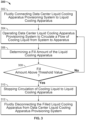
- FIG. 3 this figure illustrates an example method 300 performed with a data center liquid cooling apparatus provisioning system, such as the system 200.
- the method 300 may be performed by or with the control system 999.
- method 300 is an example of a fill or commissioning operation, in which the system 200 is operated to fill the liquid cooling apparatus 906 with a sufficient volume of cooling liquid prior to the apparatus 906 being placed into service in a data center.
- Method 300 may begin at step 302, which includes fluidly connecting the data center liquid cooling device provisioning system 200 to the liquid cooling apparatus 906.
- the dripless disconnect of the outlet 210 is connected to the fluid inlet of the apparatus 906, and the dripless disconnect of the inlet 212 is connected to the fluid outlet of the apparatus 906.
- Method 300 may continue at step 304, which includes operating the system 200 to circulate a flow of cooling liquid from the system 200 to the apparatus 906.
- control system 999 may be initiated to operate the pump 206 to flow cooling liquid from the supply tank 204 through the filter 208 and toward the outlet 210.
- the check valve 209 may prevent a backflow of the cooling liquid (or other fluid) from the outlet 210 toward the pump 206.
- the pumped cooling liquid flows from the outlet 210 into the liquid cooling apparatus 906.
- the solenoid valve labeled 218 is used during step 304. Initially in step 304, the solenoid valve 218 is left in an open position, thus allowing cooling liquid to flow into the waste tank 220 (e.g., from the supply tank 204, through the liquid cooling apparatus 906, and into the waste tank 220), thereby purging air from the liquid cooling apparatus 906. After a pre-determined time, for example, the solenoid labeled 218 is automatically closed. By closing the solenoid valve 218, and with the pump 206 continuing to run to flow cooling liquid into the liquid cooling apparatus 906, pressure increases in cooling liquid flow circuit 202.
- Method 300 may continue at step 306, which includes determining a fill amount of the liquid cooling apparatus 906.
- the sensor 222 may sense a fluid pressure at the inlet 212, which is in fluid communication with the liquid cooling device 906.
- the sensed fluid pressure at the inlet 212 may be the same as or substantially the same as the fluid pressure in the liquid cooling apparatus 906 during the fill operation.
- a particular fluid pressure measured by the sensor 222 may correspond to a particular fill level.
- Method 300 may continue at step 308, which includes a determination of whether the fill level of the liquid cooling apparatus 906 is sufficient.
- the pressure determined by the pressure sensor 222 may indicate (e.g., to the control system 999) that the liquid cooling apparatus 906 is sufficiently filled.
- the fluid pressure that corresponds to a sufficiently filled liquid cooling apparatus 906 is or is about a normal operating fluid pressure of the liquid cooling apparatus 906 in a data center cooling system. If the fill level is sufficient, method 300 proceeds to step 310. If the fill level is insufficient, then method 300 returns to step 304.
- Method step 310 includes stopping the circulation of cooling liquid to liquid cooling apparatus.
- the control system 999 may, based on the measured fluid pressure in step 306 indicating that the liquid cooling apparatus 906 is sufficiently filled, stop the pump 206 from flowing the cooling liquid from the supply tank 204 to the apparatus 906.
- Method 300 may continue at step 312, which includes fluidly disconnecting the filled liquid cooling apparatus 906 from data center liquid cooling apparatus provisioning system 200.
- the dripless disconnects on outlet 210 and inlet 212 may be disconnected from the liquid cooling apparatus 906.
- Cooling liquid that has been circulated into the liquid cooling apparatus 906 remains within the apparatus 906 (and the apparatus is now commissioned), while cooling liquid in the cooling liquid flow circuit 202 remains within the flow circuit 202.
- method 300 may include other steps as well.
- the liquid cooling apparatus 906 may become decoupled from the outlet 210 and/or the inlet 212 during the fill operations.
- the liquid cooling apparatus 906 may not have been properly secured to the outlet 210 and/or the inlet 212. In such cases, the dripless disconnects may not open to allow fluid flow therethrough.
- the pump 206 is circulating cooling liquid from the supply tank 204 toward the outlet 210 in such situations, fluid pressure may uncontrollably build up in the liquid cooling flow circuit 202.
- the check valve 216 may be set to a particular fluid pressure (e.g., 25 psi) that is indicative of this uncontrollable build up in the liquid cooling flow circuit 202. Upon reaching the set fluid pressure, check valve 216 allows cooling liquid to flow through the bypass line 214 to the cooling liquid waste tank 220 (e.g., a short circuit between supply tank 204 and waste tank 220).
- a particular fluid pressure e.g. 25 psi
- some cooling liquid may be circulated from the supply tank 204, through the liquid cooling apparatus 906, and into the waste tank 220 during a fill operation.
- air that resides within the liquid cooling apparatus 906 during a fill operation may be pushed out of the apparatus 906 and into the waste tank 220 by incoming cooling liquid circulated from the supply tank 204.
- some excess cooling liquid may be circulated into the waste tank 220 during the fill operation.
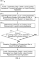
- FIG. 4 this figure illustrates another example method 400 performed with a data center liquid cooling apparatus provisioning system, such as the system 200.
- the method 400 may be performed by or with the control system 999.
- method 400 is an example of an evacuation or decommissioning operation, in which the system 200 is operated to evacuate the liquid cooling apparatus 906 of cooling liquid prior to the apparatus 906 being serviced or decommissioned.
- Method 400 may begin at step 402, which includes fluidly connecting the data center liquid cooling apparatus provisioning system 200 to the liquid cooling apparatus 906.
- the dripless disconnect of the outlet 210 is connected to the fluid inlet of the apparatus 906, and the dripless disconnect of the inlet 212 is connected to the fluid outlet of the apparatus 906.
- Method 400 may continue at step 404, which includes operating the data center liquid cooling apparatus provisioning system to circulate a flow of pressurized gas from the system 200 to the apparatus 906.
- control system 999 may be initiated to operate the compressor 252 to flow pressurized gas through the regulator 254 and into the reservoir 262.
- the reservoir 262 may already hold a sufficient supply of pressurized gas (e.g., air).
- a flow of pressurized gas is circulated through the check valve 264 (which prevents a backflow of gas and/or cooling liquid from the outlet 210) and through the outlet 210 into the liquid cooling apparatus 906.
- step 404 also includes the control system 999 opening the solenoid valve 266 to allow the flow of pressurized gas to the outlet 210.
- this solenoid valve 266 is closed during a fill operation to, e.g., prevent cooling liquid from entering the pressurized gas evacuation sub-assembly 250 through the bypass line 214.
- the pressure sensor 260 may sense that an over-pressurization situation is occurring in the pressurized gas evacuation sub-assembly 250 (e.g., a gas pressure above 40 psi between the solenoid valve 256 and the gas reservoir 262). In such cases, solenoid valve 254 may close to prevent further over-pressurization. Additionally, the regulator 254 may be set to shut down the gas compressor 252 at a particular set pressure (e.g., a gas pressure about 40 psi).
- pressure relief valve 258 may open (e.g., at 50 psi) to relieve the over-pressurization.
- the regulator 254 may include a pressure relief valve (not specifically shown) that operates to open (e.g., at a particular pressure) to relieve the over-pressurization.
- Method 400 may continue at step 406, which includes determining an amount of cooling liquid that remains in the liquid cooling apparatus 906. For example, as previously described, in some aspects, step 406 may continue until an operator visually determines if cooling liquid is flowing from the liquid cooling apparatus 906 to the waste tank 220.
- Method 400 may continue at step 408, which includes a determination of whether the determined amount of cooling liquid left in the liquid cooling apparatus exceeds a particular amount. For example, as previously described, in some aspects, step 408 may continue until an operator visually determines if cooling liquid is flowing from the liquid cooling apparatus 906 to the waste tank 220. If flow continues, i.e., the determined amount exceeds the threshold level, then method 400 returns to step 404. If the determined amount of cooling liquid is below the threshold level, then method 400 proceeds to step 410.
- Method step 410 includes stopping circulation of pressurized gas to the liquid cooling apparatus 906.
- the control system 999 may stop the operation of the compressor 252.
- the control system 999 may close the solenoid valve 266.
- step 408 includes the control system 999 closing the solenoid valve 266, closing the solenoid valve 256, and shutting off the gas compressor 252 (in that order or in another order).
- Method 400 may continue at step 412, which includes fluidly disconnecting the filled liquid cooling apparatus 906 from data center liquid cooling apparatus provisioning system 200.
- step 412 includes fluidly disconnecting the filled liquid cooling apparatus 906 from data center liquid cooling apparatus provisioning system 200.
- the dripless disconnects on outlet 210 and inlet 212 may be disconnected from the liquid cooling apparatus 906.
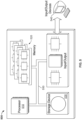
- FIG. 5 is a schematic diagram of a control system (or controller) 500 of a data center liquid cooling apparatus provisioning unit, such as the data center liquid cooling apparatus provisioning system 100 shown in FIG. 1 or the data center liquid cooling apparatus provisioning system 200 shown schematically in FIG. 2 .
- the system 500 can be used for the operations described in association with any of the computer-implemented methods described previously, for example as or as part of the HMI 120 or control system 999 or other controllers described herein.
- the system 500 is intended to include various forms of digital computers, such as laptops, desktops, workstations, personal digital assistants, servers, blade servers, mainframes, and other appropriate computers.
- the system 500 can also include mobile devices, such as personal digital assistants, cellular telephones, smartphones, and other similar computing devices.
- the system can include portable storage media, such as, Universal Serial Bus (USB) flash drives.
- USB flash drives may store operating systems and other applications.
- the USB flash drives can include input/output components, such as a wireless transmitter or USB connector that may be inserted into a USB port of another computing device.
- the system 500 includes a processor 510, a memory 520, a storage device 530, and an input/output device 540. Each of the components 510, 520, 530, and 540 are interconnected using a system bus 550.
- the processor 510 is capable of processing instructions for execution within the system 500.
- the processor may be designed using any of a number of architectures.
- the processor 510 may be a CISC (Complex Instruction Set Computers) processor, a RISC (Reduced Instruction Set Computer) processor, or a MISC (Minimal Instruction Set Computer) processor.
- the processor 510 is a single-threaded processor. In another implementation, the processor 510 is a multi-threaded processor.
- the processor 510 is capable of processing instructions stored in the memory 520 or on the storage device 530 to display graphical information for a user interface on the input/output device 540.
- the memory 520 stores information within the system 500.
- the memory 520 is a computer-readable medium.
- the memory 520 is a volatile memory unit.
- the memory 520 is a non-volatile memory unit.
- the storage device 530 is capable of providing mass storage for the system 500.
- the storage device 530 is a computer-readable medium.
- the storage device 530 may be a floppy disk device, a hard disk device, an optical disk device, or a tape device.
- the input/output device 540 provides input/output operations for the system 500.
- the input/output device 540 includes a keyboard and/or pointing device.
- the input/output device 540 includes a display unit for displaying graphical user interfaces.
- the features described can be implemented in digital electronic circuitry, or in computer hardware, firmware, software, or in combinations of them.
- the apparatus can be implemented in a computer program product tangibly embodied in an information carrier, e.g., in a machine-readable storage device for execution by a programmable processor; and method steps can be performed by a programmable processor executing a program of instructions to perform functions of the described implementations by operating on input data and generating output.
- the described features can be implemented advantageously in one or more computer programs that are executable on a programmable system including at least one programmable processor coupled to receive data and instructions from, and to transmit data and instructions to, a data storage system, at least one input device, and at least one output device.
- a computer program is a set of instructions that can be used, directly or indirectly, in a computer to perform a certain activity or bring about a certain result.
- a computer program can be written in any form of programming language, including compiled or interpreted languages, and it can be deployed in any form, including as a stand-alone program or as a module, component, subroutine, or other unit suitable for use in a computing environment.
- Suitable processors for the execution of a program of instructions include, by way of example, both general and special purpose microprocessors, and the sole processor or one of multiple processors of any kind of computer.
- a processor will receive instructions and data from a read-only memory or a random access memory or both.
- the essential elements of a computer are a processor for executing instructions and one or more memories for storing instructions and data.
- a computer will also include, or be operatively coupled to communicate with, one or more mass storage devices for storing data files; such devices include magnetic disks, such as internal hard disks and removable disks; magneto-optical disks; and optical disks.
- Storage devices suitable for tangibly embodying computer program instructions and data include all forms of non-volatile memory, including by way of example semiconductor memory devices, such as EPROM, EEPROM, and flash memory devices; magnetic disks such as internal hard disks and removable disks; magneto-optical disks; and CD-ROM and DVD-ROM disks.
- semiconductor memory devices such as EPROM, EEPROM, and flash memory devices
- magnetic disks such as internal hard disks and removable disks
- magneto-optical disks and CD-ROM and DVD-ROM disks.
- the processor and the memory can be supplemented by, or incorporated in, ASICs (application-specific integrated circuits).
- ASICs application-specific integrated circuits
- the features can be implemented on a computer having a display device such as a CRT (cathode ray tube) or LCD (liquid crystal display) monitor for displaying information to the user and a keyboard and a pointing device such as a mouse or a trackball by which the user can provide input to the computer. Additionally, such activities can be implemented via touchscreen flat-panel displays and other appropriate mechanisms.
- a display device such as a CRT (cathode ray tube) or LCD (liquid crystal display) monitor for displaying information to the user and a keyboard and a pointing device such as a mouse or a trackball by which the user can provide input to the computer.
- a keyboard and a pointing device such as a mouse or a trackball by which the user can provide input to the computer.
- activities can be implemented via touchscreen flat-panel displays and other appropriate mechanisms.
- the features can be implemented in a control system that includes a back-end component, such as a data server, or that includes a middleware component, such as an application server or an Internet server, or that includes a front-end component, such as a client computer having a graphical user interface or an Internet browser, or any combination of them.
- the components of the system can be connected by any form or medium of digital data communication such as a communication network. Examples of communication networks include a local area network (“LAN”), a wide area network (“WAN”), peer-to-peer networks (having ad-hoc or static members), grid computing infrastructures, and the Internet.
- LAN local area network
- WAN wide area network
- peer-to-peer networks having ad-hoc or static members
- grid computing infrastructures and the Internet.
Landscapes
- Engineering & Computer Science (AREA)
- Microelectronics & Electronic Packaging (AREA)
- Physics & Mathematics (AREA)
- Thermal Sciences (AREA)
- Computer Hardware Design (AREA)
- General Engineering & Computer Science (AREA)
- Cooling Or The Like Of Electrical Apparatus (AREA)
- Management, Administration, Business Operations System, And Electronic Commerce (AREA)
- Devices That Are Associated With Refrigeration Equipment (AREA)
Applications Claiming Priority (3)
| Application Number | Priority Date | Filing Date | Title |
|---|---|---|---|
| US201862775513P | 2018-12-05 | 2018-12-05 | |
| US16/250,418 US10869412B2 (en) | 2018-12-05 | 2019-01-17 | Provisioning data center server cooling equipment |
| PCT/US2019/044409 WO2020117326A1 (en) | 2018-12-05 | 2019-07-31 | Provisioning data center server cooling equipment |
Publications (2)
| Publication Number | Publication Date |
|---|---|
| EP3785502A1 EP3785502A1 (en) | 2021-03-03 |
| EP3785502B1 true EP3785502B1 (en) | 2023-04-12 |
Family
ID=70970699
Family Applications (1)
| Application Number | Title | Priority Date | Filing Date |
|---|---|---|---|
| EP19752835.9A Active EP3785502B1 (en) | 2018-12-05 | 2019-07-31 | Provisioning data center server cooling equipment |
Country Status (6)
| Country | Link |
|---|---|
| US (2) | US10869412B2 (da) |
| EP (1) | EP3785502B1 (da) |
| CN (2) | CN113170594B (da) |
| DK (1) | DK3785502T3 (da) |
| FI (1) | FI3785502T3 (da) |
| WO (1) | WO2020117326A1 (da) |
Families Citing this family (8)
| Publication number | Priority date | Publication date | Assignee | Title |
|---|---|---|---|---|
| US11229143B2 (en) * | 2019-10-29 | 2022-01-18 | Asia Vital Components Co., Ltd. | Liquid-cooling heat dissipation system capable of regulating water quality |
| US11445631B2 (en) * | 2020-03-19 | 2022-09-13 | Baidu Usa Llc | High performance computing based holistic liquid cooled rack cost optimization |
| CN114942868B (zh) * | 2022-04-08 | 2026-04-21 | 阿里巴巴(中国)有限公司 | 数据中心的测试设备、测试方法及数据中心测试系统 |
| US12520452B2 (en) | 2022-05-04 | 2026-01-06 | Hoffman Enclosures Inc. | Replaceable pump unit for cooling systems |
| WO2023215620A1 (en) * | 2022-05-05 | 2023-11-09 | Hoffman Enclosures Inc. | Liquid cooling system fill kit and method of use |
| US12349311B2 (en) * | 2022-07-28 | 2025-07-01 | Dell Products L.P. | Systems and methods for filling and draining liquid of a liquid cooling system |
| US20240314986A1 (en) * | 2023-03-14 | 2024-09-19 | Schneider Electric It Corporation | Manifold and methods to implement liquid cooling in an uninterruptible power supply |
| US20240373585A1 (en) * | 2023-05-07 | 2024-11-07 | Abdul Luke Gomez | GSGDG 7154 Computer System |
Family Cites Families (21)
| Publication number | Priority date | Publication date | Assignee | Title |
|---|---|---|---|---|
| US4513696A (en) | 1982-05-24 | 1985-04-30 | Toyo Kogyo Co., Ltd. | Apparatus for charging cooling liquid to engine cooling system |
| JP2748732B2 (ja) | 1991-07-19 | 1998-05-13 | 日本電気株式会社 | 液体冷媒循環システム |
| US6161578A (en) * | 1996-10-09 | 2000-12-19 | Colder Products Company | Low spill high flow quick coupling valve assembly |
| US6880351B2 (en) * | 2001-09-05 | 2005-04-19 | Be Intellectual Property, Inc. | Liquid galley refrigeration system for aircraft |
| US7043933B1 (en) | 2003-08-26 | 2006-05-16 | Isothermal Systems Research, Inc. | Spray coolant reservoir system |
| US7106590B2 (en) * | 2003-12-03 | 2006-09-12 | International Business Machines Corporation | Cooling system and method employing multiple dedicated coolant conditioning units for cooling multiple electronics subsystems |
| US7270174B2 (en) | 2003-12-16 | 2007-09-18 | International Business Machines Corporation | Method, system and program product for automatically checking coolant loops of a cooling system for a computing environment |
| US20070193721A1 (en) | 2006-02-21 | 2007-08-23 | Tilton Donald E | Automated Venting and Refilling of Multiple Liquid Cooling Systems |
| US7508665B1 (en) | 2006-10-18 | 2009-03-24 | Isothermal Systems Research, Inc. | Server farm liquid thermal management system |
| US10123463B2 (en) * | 2008-08-11 | 2018-11-06 | Green Revolution Cooling, Inc. | Liquid submerged, horizontal computer server rack and systems and method of cooling such a server rack |
| US8500419B2 (en) * | 2008-11-10 | 2013-08-06 | Schlumberger Technology Corporation | Subsea pumping system with interchangable pumping units |
| US9010141B2 (en) | 2010-04-19 | 2015-04-21 | Chilldyne, Inc. | Computer cooling system and method of use |
| US20110253347A1 (en) * | 2010-04-19 | 2011-10-20 | Steve Harrington | Vacuum Pumped Liquid Cooling System for Computers |
| JP6191104B2 (ja) * | 2012-09-07 | 2017-09-06 | 富士通株式会社 | 冷媒供給ユニット、冷却ユニット及び電子機器 |
| US9464854B2 (en) * | 2013-02-01 | 2016-10-11 | Dell Products, Lp | Techniques for controlling vapor pressure in an immersion cooling tank |
| US8820351B1 (en) * | 2013-06-25 | 2014-09-02 | Chilldyne, Inc. | No drip hot swap connector and method of use |
| WO2016012379A1 (de) * | 2014-07-21 | 2016-01-28 | Nidec Gpm Gmbh | Kühlmittelpumpe mit integrierter regelung |
| US9398731B1 (en) * | 2014-09-23 | 2016-07-19 | Google Inc. | Cooling electronic devices in a data center |
| US9713286B2 (en) * | 2015-03-03 | 2017-07-18 | International Business Machines Corporation | Active control for two-phase cooling |
| US9980415B2 (en) * | 2015-08-20 | 2018-05-22 | Toyota Motor Engineering & Manufacturing North America, Inc. | Configurable double-sided modular jet impingement assemblies for electronics cooling |
| US10342163B2 (en) * | 2015-12-02 | 2019-07-02 | Google Llc | Cooling a data center |
-
2019
- 2019-01-17 US US16/250,418 patent/US10869412B2/en active Active
- 2019-07-31 DK DK19752835.9T patent/DK3785502T3/da active
- 2019-07-31 CN CN201980036830.0A patent/CN113170594B/zh active Active
- 2019-07-31 CN CN202210439771.5A patent/CN114745926B/zh active Active
- 2019-07-31 WO PCT/US2019/044409 patent/WO2020117326A1/en not_active Ceased
- 2019-07-31 EP EP19752835.9A patent/EP3785502B1/en active Active
- 2019-07-31 FI FIEP19752835.9T patent/FI3785502T3/fi active
-
2020
- 2020-11-11 US US17/095,554 patent/US11197397B2/en active Active
Also Published As
| Publication number | Publication date |
|---|---|
| US20200187388A1 (en) | 2020-06-11 |
| CN113170594B (zh) | 2022-05-17 |
| CN114745926B (zh) | 2024-11-01 |
| DK3785502T3 (da) | 2023-07-10 |
| US20210068309A1 (en) | 2021-03-04 |
| FI3785502T3 (fi) | 2023-06-08 |
| EP3785502A1 (en) | 2021-03-03 |
| US11197397B2 (en) | 2021-12-07 |
| US10869412B2 (en) | 2020-12-15 |
| CN113170594A (zh) | 2021-07-23 |
| WO2020117326A1 (en) | 2020-06-11 |
| CN114745926A (zh) | 2022-07-12 |
Similar Documents
| Publication | Publication Date | Title |
|---|---|---|
| US11197397B2 (en) | Provisioning data center server cooling equipment | |
| US11602075B2 (en) | Cooling apparatus providing immersion cooling | |
| US9161480B2 (en) | Vacuum pumped liquid cooling system for computers | |
| US11754227B2 (en) | Gas charging device | |
| KR20230013245A (ko) | 극저온 유체를 전달하기 위한 장치 및 방법 | |
| US20180326463A1 (en) | Method for contamination prevention in fluid storage tank requiring temperature control, and device therefor | |
| US20100051253A1 (en) | Semiconductor processing heat exchanger system | |
| HK40076101A (en) | Provisioning data center server cooling equipment | |
| HK40054141A (en) | Provisioning data center server cooling equipment | |
| HK40054141B (en) | Provisioning data center server cooling equipment | |
| HK40076101B (zh) | 供应数据中心服务器冷却设备 | |
| JP2002181427A (ja) | 自動回収機構付き冷却液循環装置 | |
| JP6033321B2 (ja) | 給湯システム | |
| CN211926256U (zh) | 一种蒸发器的冷却循环系统 | |
| CN208752973U (zh) | 一种用于乏燃料运输容器的离线循环冷却装置 | |
| CN222911400U (zh) | 一种冷却液漏液处理装置及半导体设备 | |
| CN114501954A (zh) | 液冷系统及控制方法 | |
| CN217644090U (zh) | 补液装置与冷却系统 | |
| US12349311B2 (en) | Systems and methods for filling and draining liquid of a liquid cooling system | |
| CN119050554B (zh) | 热管理控制方法和装置 | |
| CN221444896U (zh) | 一种脉动真空压力蒸汽灭菌器的废热利用系统 | |
| CN221486610U (zh) | 液体循环系统、液冷装置及储能装置 | |
| CN108922644A (zh) | 一种离线循环冷却装置及冷却方法 | |
| CN115045832A (zh) | 真空获得设备、磁共振系统及真空获得方法 | |
| CN119022241A (zh) | 一种冷却液漏液处理装置及方法 |
Legal Events
| Date | Code | Title | Description |
|---|---|---|---|
| STAA | Information on the status of an ep patent application or granted ep patent |
Free format text: STATUS: UNKNOWN |
|
| STAA | Information on the status of an ep patent application or granted ep patent |
Free format text: STATUS: THE INTERNATIONAL PUBLICATION HAS BEEN MADE |
|
| PUAI | Public reference made under article 153(3) epc to a published international application that has entered the european phase |
Free format text: ORIGINAL CODE: 0009012 |
|
| STAA | Information on the status of an ep patent application or granted ep patent |
Free format text: STATUS: REQUEST FOR EXAMINATION WAS MADE |
|
| 17P | Request for examination filed |
Effective date: 20201123 |
|
| AK | Designated contracting states |
Kind code of ref document: A1 Designated state(s): AL AT BE BG CH CY CZ DE DK EE ES FI FR GB GR HR HU IE IS IT LI LT LU LV MC MK MT NL NO PL PT RO RS SE SI SK SM TR |
|
| AX | Request for extension of the european patent |
Extension state: BA ME |
|
| DAV | Request for validation of the european patent (deleted) | ||
| DAX | Request for extension of the european patent (deleted) | ||
| GRAP | Despatch of communication of intention to grant a patent |
Free format text: ORIGINAL CODE: EPIDOSNIGR1 |
|
| STAA | Information on the status of an ep patent application or granted ep patent |
Free format text: STATUS: GRANT OF PATENT IS INTENDED |
|
| INTG | Intention to grant announced |
Effective date: 20221027 |
|
| GRAS | Grant fee paid |
Free format text: ORIGINAL CODE: EPIDOSNIGR3 |
|
| GRAA | (expected) grant |
Free format text: ORIGINAL CODE: 0009210 |
|
| STAA | Information on the status of an ep patent application or granted ep patent |
Free format text: STATUS: THE PATENT HAS BEEN GRANTED |
|
| AK | Designated contracting states |
Kind code of ref document: B1 Designated state(s): AL AT BE BG CH CY CZ DE DK EE ES FI FR GB GR HR HU IE IS IT LI LT LU LV MC MK MT NL NO PL PT RO RS SE SI SK SM TR |
|
| REG | Reference to a national code |
Ref country code: GB Ref legal event code: FG4D |
|
| REG | Reference to a national code |
Ref country code: CH Ref legal event code: EP |
|
| REG | Reference to a national code |
Ref country code: DE Ref legal event code: R096 Ref document number: 602019027494 Country of ref document: DE |
|
| REG | Reference to a national code |
Ref country code: IE Ref legal event code: FG4D |
|
| REG | Reference to a national code |
Ref country code: AT Ref legal event code: REF Ref document number: 1560521 Country of ref document: AT Kind code of ref document: T Effective date: 20230515 |
|
| REG | Reference to a national code |
Ref country code: FI Ref legal event code: FGE |
|
| P01 | Opt-out of the competence of the unified patent court (upc) registered |
Effective date: 20230518 |
|
| REG | Reference to a national code |
Ref country code: NL Ref legal event code: FP |
|
| REG | Reference to a national code |
Ref country code: DK Ref legal event code: T3 Effective date: 20230704 |
|
| REG | Reference to a national code |
Ref country code: SE Ref legal event code: TRGR |
|
| REG | Reference to a national code |
Ref country code: LT Ref legal event code: MG9D |
|
| REG | Reference to a national code |
Ref country code: AT Ref legal event code: MK05 Ref document number: 1560521 Country of ref document: AT Kind code of ref document: T Effective date: 20230412 |
|
| PG25 | Lapsed in a contracting state [announced via postgrant information from national office to epo] |
Ref country code: PT Free format text: LAPSE BECAUSE OF FAILURE TO SUBMIT A TRANSLATION OF THE DESCRIPTION OR TO PAY THE FEE WITHIN THE PRESCRIBED TIME-LIMIT Effective date: 20230814 Ref country code: NO Free format text: LAPSE BECAUSE OF FAILURE TO SUBMIT A TRANSLATION OF THE DESCRIPTION OR TO PAY THE FEE WITHIN THE PRESCRIBED TIME-LIMIT Effective date: 20230712 Ref country code: ES Free format text: LAPSE BECAUSE OF FAILURE TO SUBMIT A TRANSLATION OF THE DESCRIPTION OR TO PAY THE FEE WITHIN THE PRESCRIBED TIME-LIMIT Effective date: 20230412 Ref country code: AT Free format text: LAPSE BECAUSE OF FAILURE TO SUBMIT A TRANSLATION OF THE DESCRIPTION OR TO PAY THE FEE WITHIN THE PRESCRIBED TIME-LIMIT Effective date: 20230412 |
|
| PG25 | Lapsed in a contracting state [announced via postgrant information from national office to epo] |
Ref country code: RS Free format text: LAPSE BECAUSE OF FAILURE TO SUBMIT A TRANSLATION OF THE DESCRIPTION OR TO PAY THE FEE WITHIN THE PRESCRIBED TIME-LIMIT Effective date: 20230412 Ref country code: PL Free format text: LAPSE BECAUSE OF FAILURE TO SUBMIT A TRANSLATION OF THE DESCRIPTION OR TO PAY THE FEE WITHIN THE PRESCRIBED TIME-LIMIT Effective date: 20230412 Ref country code: LV Free format text: LAPSE BECAUSE OF FAILURE TO SUBMIT A TRANSLATION OF THE DESCRIPTION OR TO PAY THE FEE WITHIN THE PRESCRIBED TIME-LIMIT Effective date: 20230412 Ref country code: LT Free format text: LAPSE BECAUSE OF FAILURE TO SUBMIT A TRANSLATION OF THE DESCRIPTION OR TO PAY THE FEE WITHIN THE PRESCRIBED TIME-LIMIT Effective date: 20230412 Ref country code: IS Free format text: LAPSE BECAUSE OF FAILURE TO SUBMIT A TRANSLATION OF THE DESCRIPTION OR TO PAY THE FEE WITHIN THE PRESCRIBED TIME-LIMIT Effective date: 20230812 Ref country code: HR Free format text: LAPSE BECAUSE OF FAILURE TO SUBMIT A TRANSLATION OF THE DESCRIPTION OR TO PAY THE FEE WITHIN THE PRESCRIBED TIME-LIMIT Effective date: 20230412 Ref country code: GR Free format text: LAPSE BECAUSE OF FAILURE TO SUBMIT A TRANSLATION OF THE DESCRIPTION OR TO PAY THE FEE WITHIN THE PRESCRIBED TIME-LIMIT Effective date: 20230713 |
|
| REG | Reference to a national code |
Ref country code: DE Ref legal event code: R097 Ref document number: 602019027494 Country of ref document: DE |
|
| PG25 | Lapsed in a contracting state [announced via postgrant information from national office to epo] |
Ref country code: SK Free format text: LAPSE BECAUSE OF FAILURE TO SUBMIT A TRANSLATION OF THE DESCRIPTION OR TO PAY THE FEE WITHIN THE PRESCRIBED TIME-LIMIT Effective date: 20230412 |
|
| PG25 | Lapsed in a contracting state [announced via postgrant information from national office to epo] |
Ref country code: SM Free format text: LAPSE BECAUSE OF FAILURE TO SUBMIT A TRANSLATION OF THE DESCRIPTION OR TO PAY THE FEE WITHIN THE PRESCRIBED TIME-LIMIT Effective date: 20230412 Ref country code: SK Free format text: LAPSE BECAUSE OF FAILURE TO SUBMIT A TRANSLATION OF THE DESCRIPTION OR TO PAY THE FEE WITHIN THE PRESCRIBED TIME-LIMIT Effective date: 20230412 Ref country code: RO Free format text: LAPSE BECAUSE OF FAILURE TO SUBMIT A TRANSLATION OF THE DESCRIPTION OR TO PAY THE FEE WITHIN THE PRESCRIBED TIME-LIMIT Effective date: 20230412 Ref country code: EE Free format text: LAPSE BECAUSE OF FAILURE TO SUBMIT A TRANSLATION OF THE DESCRIPTION OR TO PAY THE FEE WITHIN THE PRESCRIBED TIME-LIMIT Effective date: 20230412 Ref country code: CZ Free format text: LAPSE BECAUSE OF FAILURE TO SUBMIT A TRANSLATION OF THE DESCRIPTION OR TO PAY THE FEE WITHIN THE PRESCRIBED TIME-LIMIT Effective date: 20230412 |
|
| PLBE | No opposition filed within time limit |
Free format text: ORIGINAL CODE: 0009261 |
|
| STAA | Information on the status of an ep patent application or granted ep patent |
Free format text: STATUS: NO OPPOSITION FILED WITHIN TIME LIMIT |
|
| PG25 | Lapsed in a contracting state [announced via postgrant information from national office to epo] |
Ref country code: MC Free format text: LAPSE BECAUSE OF FAILURE TO SUBMIT A TRANSLATION OF THE DESCRIPTION OR TO PAY THE FEE WITHIN THE PRESCRIBED TIME-LIMIT Effective date: 20230412 |
|
| PG25 | Lapsed in a contracting state [announced via postgrant information from national office to epo] |
Ref country code: MC Free format text: LAPSE BECAUSE OF FAILURE TO SUBMIT A TRANSLATION OF THE DESCRIPTION OR TO PAY THE FEE WITHIN THE PRESCRIBED TIME-LIMIT Effective date: 20230412 |
|
| 26N | No opposition filed |
Effective date: 20240115 |
|
| PG25 | Lapsed in a contracting state [announced via postgrant information from national office to epo] |
Ref country code: LU Free format text: LAPSE BECAUSE OF NON-PAYMENT OF DUE FEES Effective date: 20230731 |
|
| PG25 | Lapsed in a contracting state [announced via postgrant information from national office to epo] |
Ref country code: LU Free format text: LAPSE BECAUSE OF NON-PAYMENT OF DUE FEES Effective date: 20230731 |
|
| PG25 | Lapsed in a contracting state [announced via postgrant information from national office to epo] |
Ref country code: SI Free format text: LAPSE BECAUSE OF FAILURE TO SUBMIT A TRANSLATION OF THE DESCRIPTION OR TO PAY THE FEE WITHIN THE PRESCRIBED TIME-LIMIT Effective date: 20230412 |
|
| PG25 | Lapsed in a contracting state [announced via postgrant information from national office to epo] |
Ref country code: SI Free format text: LAPSE BECAUSE OF FAILURE TO SUBMIT A TRANSLATION OF THE DESCRIPTION OR TO PAY THE FEE WITHIN THE PRESCRIBED TIME-LIMIT Effective date: 20230412 Ref country code: IT Free format text: LAPSE BECAUSE OF FAILURE TO SUBMIT A TRANSLATION OF THE DESCRIPTION OR TO PAY THE FEE WITHIN THE PRESCRIBED TIME-LIMIT Effective date: 20230412 |
|
| PG25 | Lapsed in a contracting state [announced via postgrant information from national office to epo] |
Ref country code: BG Free format text: LAPSE BECAUSE OF FAILURE TO SUBMIT A TRANSLATION OF THE DESCRIPTION OR TO PAY THE FEE WITHIN THE PRESCRIBED TIME-LIMIT Effective date: 20230412 |
|
| PG25 | Lapsed in a contracting state [announced via postgrant information from national office to epo] |
Ref country code: BG Free format text: LAPSE BECAUSE OF FAILURE TO SUBMIT A TRANSLATION OF THE DESCRIPTION OR TO PAY THE FEE WITHIN THE PRESCRIBED TIME-LIMIT Effective date: 20230412 |
|
| PG25 | Lapsed in a contracting state [announced via postgrant information from national office to epo] |
Ref country code: CY Free format text: LAPSE BECAUSE OF FAILURE TO SUBMIT A TRANSLATION OF THE DESCRIPTION OR TO PAY THE FEE WITHIN THE PRESCRIBED TIME-LIMIT; INVALID AB INITIO Effective date: 20190731 |
|
| PG25 | Lapsed in a contracting state [announced via postgrant information from national office to epo] |
Ref country code: HU Free format text: LAPSE BECAUSE OF FAILURE TO SUBMIT A TRANSLATION OF THE DESCRIPTION OR TO PAY THE FEE WITHIN THE PRESCRIBED TIME-LIMIT; INVALID AB INITIO Effective date: 20190731 |
|
| PGFP | Annual fee paid to national office [announced via postgrant information from national office to epo] |
Ref country code: NL Payment date: 20250726 Year of fee payment: 7 |
|
| PGFP | Annual fee paid to national office [announced via postgrant information from national office to epo] |
Ref country code: FI Payment date: 20250725 Year of fee payment: 7 |
|
| PGFP | Annual fee paid to national office [announced via postgrant information from national office to epo] |
Ref country code: DK Payment date: 20250725 Year of fee payment: 7 Ref country code: DE Payment date: 20250729 Year of fee payment: 7 |
|
| PGFP | Annual fee paid to national office [announced via postgrant information from national office to epo] |
Ref country code: BE Payment date: 20250728 Year of fee payment: 7 Ref country code: GB Payment date: 20250728 Year of fee payment: 7 |
|
| PGFP | Annual fee paid to national office [announced via postgrant information from national office to epo] |
Ref country code: FR Payment date: 20250728 Year of fee payment: 7 |
|
| PGFP | Annual fee paid to national office [announced via postgrant information from national office to epo] |
Ref country code: CH Payment date: 20250801 Year of fee payment: 7 Ref country code: SE Payment date: 20250727 Year of fee payment: 7 |
|
| PGFP | Annual fee paid to national office [announced via postgrant information from national office to epo] |
Ref country code: IE Payment date: 20250728 Year of fee payment: 7 |
|
| PG25 | Lapsed in a contracting state [announced via postgrant information from national office to epo] |
Ref country code: TR Free format text: LAPSE BECAUSE OF FAILURE TO SUBMIT A TRANSLATION OF THE DESCRIPTION OR TO PAY THE FEE WITHIN THE PRESCRIBED TIME-LIMIT Effective date: 20230412 |