EP3786003B1 - Appareil de coussin de sécurité gonflable destiné à un véhicule - Google Patents
Appareil de coussin de sécurité gonflable destiné à un véhicule Download PDFInfo
- Publication number
- EP3786003B1 EP3786003B1 EP19792081.2A EP19792081A EP3786003B1 EP 3786003 B1 EP3786003 B1 EP 3786003B1 EP 19792081 A EP19792081 A EP 19792081A EP 3786003 B1 EP3786003 B1 EP 3786003B1
- Authority
- EP
- European Patent Office
- Prior art keywords
- rider
- vehicle
- mounting board
- airbag
- airbag cushion
- Prior art date
- Legal status (The legal status is an assumption and is not a legal conclusion. Google has not performed a legal analysis and makes no representation as to the accuracy of the status listed.)
- Active
Links
Images




Classifications
-
- B—PERFORMING OPERATIONS; TRANSPORTING
- B60—VEHICLES IN GENERAL
- B60N—SEATS SPECIALLY ADAPTED FOR VEHICLES; VEHICLE PASSENGER ACCOMMODATION NOT OTHERWISE PROVIDED FOR
- B60N2/00—Seats specially adapted for vehicles; Arrangement or mounting of seats in vehicles
- B60N2/75—Arm-rests
- B60N2/78—Arm-rests post or panel mounted
-
- B—PERFORMING OPERATIONS; TRANSPORTING
- B60—VEHICLES IN GENERAL
- B60N—SEATS SPECIALLY ADAPTED FOR VEHICLES; VEHICLE PASSENGER ACCOMMODATION NOT OTHERWISE PROVIDED FOR
- B60N2/00—Seats specially adapted for vehicles; Arrangement or mounting of seats in vehicles
- B60N2/75—Arm-rests
-
- B—PERFORMING OPERATIONS; TRANSPORTING
- B60—VEHICLES IN GENERAL
- B60N—SEATS SPECIALLY ADAPTED FOR VEHICLES; VEHICLE PASSENGER ACCOMMODATION NOT OTHERWISE PROVIDED FOR
- B60N2/00—Seats specially adapted for vehicles; Arrangement or mounting of seats in vehicles
- B60N2/75—Arm-rests
- B60N2/753—Arm-rests movable to an inoperative position
-
- B—PERFORMING OPERATIONS; TRANSPORTING
- B60—VEHICLES IN GENERAL
- B60N—SEATS SPECIALLY ADAPTED FOR VEHICLES; VEHICLE PASSENGER ACCOMMODATION NOT OTHERWISE PROVIDED FOR
- B60N2/00—Seats specially adapted for vehicles; Arrangement or mounting of seats in vehicles
- B60N2/75—Arm-rests
- B60N2/763—Arm-rests adjustable
- B60N2/777—Transversal adjustment
-
- B—PERFORMING OPERATIONS; TRANSPORTING
- B60—VEHICLES IN GENERAL
- B60R—VEHICLES, VEHICLE FITTINGS, OR VEHICLE PARTS, NOT OTHERWISE PROVIDED FOR
- B60R21/00—Arrangements or fittings on vehicles for protecting or preventing injuries to occupants or pedestrians in case of accidents or other traffic risks
- B60R21/02—Occupant safety arrangements or fittings, e.g. crash pads
- B60R21/16—Inflatable occupant restraints or confinements designed to inflate upon impact or impending impact, e.g. air bags
- B60R21/20—Arrangements for storing inflatable members in their non-use or deflated condition; Arrangement or mounting of air bag modules or components
- B60R21/21—Arrangements for storing inflatable members in their non-use or deflated condition; Arrangement or mounting of air bag modules or components in vehicle side panels, e.g. doors
-
- B—PERFORMING OPERATIONS; TRANSPORTING
- B60—VEHICLES IN GENERAL
- B60R—VEHICLES, VEHICLE FITTINGS, OR VEHICLE PARTS, NOT OTHERWISE PROVIDED FOR
- B60R21/00—Arrangements or fittings on vehicles for protecting or preventing injuries to occupants or pedestrians in case of accidents or other traffic risks
- B60R21/02—Occupant safety arrangements or fittings, e.g. crash pads
- B60R21/16—Inflatable occupant restraints or confinements designed to inflate upon impact or impending impact, e.g. air bags
- B60R21/23—Inflatable members
- B60R21/231—Inflatable members characterised by their shape, construction or spatial configuration
- B60R21/23138—Inflatable members characterised by their shape, construction or spatial configuration specially adapted for side protection
-
- B—PERFORMING OPERATIONS; TRANSPORTING
- B60—VEHICLES IN GENERAL
- B60R—VEHICLES, VEHICLE FITTINGS, OR VEHICLE PARTS, NOT OTHERWISE PROVIDED FOR
- B60R21/00—Arrangements or fittings on vehicles for protecting or preventing injuries to occupants or pedestrians in case of accidents or other traffic risks
- B60R21/02—Occupant safety arrangements or fittings, e.g. crash pads
- B60R21/16—Inflatable occupant restraints or confinements designed to inflate upon impact or impending impact, e.g. air bags
- B60R21/23—Inflatable members
- B60R21/231—Inflatable members characterised by their shape, construction or spatial configuration
- B60R21/233—Inflatable members characterised by their shape, construction or spatial configuration comprising a plurality of individual compartments; comprising two or more bag-like members, one within the other
-
- B—PERFORMING OPERATIONS; TRANSPORTING
- B60—VEHICLES IN GENERAL
- B60R—VEHICLES, VEHICLE FITTINGS, OR VEHICLE PARTS, NOT OTHERWISE PROVIDED FOR
- B60R21/00—Arrangements or fittings on vehicles for protecting or preventing injuries to occupants or pedestrians in case of accidents or other traffic risks
- B60R21/02—Occupant safety arrangements or fittings, e.g. crash pads
- B60R21/16—Inflatable occupant restraints or confinements designed to inflate upon impact or impending impact, e.g. air bags
- B60R21/23—Inflatable members
- B60R21/231—Inflatable members characterised by their shape, construction or spatial configuration
- B60R21/2334—Expansion control features
- B60R21/2338—Tethers
-
- B—PERFORMING OPERATIONS; TRANSPORTING
- B60—VEHICLES IN GENERAL
- B60R—VEHICLES, VEHICLE FITTINGS, OR VEHICLE PARTS, NOT OTHERWISE PROVIDED FOR
- B60R21/00—Arrangements or fittings on vehicles for protecting or preventing injuries to occupants or pedestrians in case of accidents or other traffic risks
- B60R21/02—Occupant safety arrangements or fittings, e.g. crash pads
- B60R21/16—Inflatable occupant restraints or confinements designed to inflate upon impact or impending impact, e.g. air bags
- B60R21/23—Inflatable members
- B60R21/237—Inflatable members characterised by the way they are folded
-
- B—PERFORMING OPERATIONS; TRANSPORTING
- B60—VEHICLES IN GENERAL
- B60R—VEHICLES, VEHICLE FITTINGS, OR VEHICLE PARTS, NOT OTHERWISE PROVIDED FOR
- B60R21/00—Arrangements or fittings on vehicles for protecting or preventing injuries to occupants or pedestrians in case of accidents or other traffic risks
- B60R21/02—Occupant safety arrangements or fittings, e.g. crash pads
- B60R21/16—Inflatable occupant restraints or confinements designed to inflate upon impact or impending impact, e.g. air bags
- B60R21/26—Inflatable occupant restraints or confinements designed to inflate upon impact or impending impact, e.g. air bags characterised by the inflation fluid source or means to control inflation fluid flow
- B60R21/264—Inflatable occupant restraints or confinements designed to inflate upon impact or impending impact, e.g. air bags characterised by the inflation fluid source or means to control inflation fluid flow using instantaneous generation of gas, e.g. pyrotechnic
-
- B—PERFORMING OPERATIONS; TRANSPORTING
- B60—VEHICLES IN GENERAL
- B60R—VEHICLES, VEHICLE FITTINGS, OR VEHICLE PARTS, NOT OTHERWISE PROVIDED FOR
- B60R21/00—Arrangements or fittings on vehicles for protecting or preventing injuries to occupants or pedestrians in case of accidents or other traffic risks
- B60R21/02—Occupant safety arrangements or fittings, e.g. crash pads
- B60R21/16—Inflatable occupant restraints or confinements designed to inflate upon impact or impending impact, e.g. air bags
- B60R21/20—Arrangements for storing inflatable members in their non-use or deflated condition; Arrangement or mounting of air bag modules or components
- B60R21/217—Inflation fluid source retainers, e.g. reaction canisters; Connection of bags, covers, diffusers or inflation fluid sources therewith or together
- B60R2021/2173—Inflation fluid source retainers, e.g. reaction canisters; Connection of bags, covers, diffusers or inflation fluid sources therewith or together the module or part thereof being movably mounted on the vehicle
-
- B—PERFORMING OPERATIONS; TRANSPORTING
- B60—VEHICLES IN GENERAL
- B60R—VEHICLES, VEHICLE FITTINGS, OR VEHICLE PARTS, NOT OTHERWISE PROVIDED FOR
- B60R21/00—Arrangements or fittings on vehicles for protecting or preventing injuries to occupants or pedestrians in case of accidents or other traffic risks
- B60R21/02—Occupant safety arrangements or fittings, e.g. crash pads
- B60R21/16—Inflatable occupant restraints or confinements designed to inflate upon impact or impending impact, e.g. air bags
- B60R21/23—Inflatable members
- B60R21/231—Inflatable members characterised by their shape, construction or spatial configuration
- B60R2021/23107—Inflatable members characterised by their shape, construction or spatial configuration the bag being integrated in a multi-bag system
Definitions
- the present invention relates to an airbag apparatus for a vehicle, and more particularly, to an airbag apparatus for a vehicle, which is inflated and expanded between a frontal airbag and a rider when the vehicle collides, and protects the rider.
- an airbag apparatus for a vehicle is a safety device that protects the rider by rapidly inflating an airbag by injecting a gas into the airbag according to a signal of an impact detection sensor upon vehicle collision.
- Such an airbag apparatus is installed in a steering wheel, a dashboard, a seat, a sidewall, etc. provided in a vehicle, and is inflated toward the front or side of a rider upon collision of a vehicle, and protects the rider.
- a vehicle may be provided with a frontal airbag expanded in front of a driver seat and a passenger seat, a curtain airbag and a side airbag expanded from the side of a rider to protect the rider, and a knee airbag to protect the rider's knees.
- the autonomous vehicle detects states of respective devices provided in the vehicle and the surroundings of the vehicle by using a high-tech sensor for recognizing objects around the vehicle and a high-performance graphic processing device, and travels while controlling driving of the respective devices provided in the vehicle according to the result of the detection.
- the high-tech sensor measures the distance between objects like a human, and detects danger and helps a driver view all areas without a blind spot.
- the graphic processing device recognizes a surrounding environment of the vehicle through various cameras, and analyzes the images and helps the vehicle drive safely.
- a LiDAR device for example, a LiDAR device, a sound wave device, a 3D camera, a radar device, and etc. may be mounted in the autonomous vehicle.
- all seats including a driver seat can freely rotate and an angle of a back of a seat can be adjusted to be horizontal by a tilting operation.
- a rider can adjust the angle of the back of the seat variously, and may rotate the seat to have a meeting facing a rider on a back seat.
- Patent Document 1 and Patent Document 2 presented below disclose a passenger protection system configuration for vehicles.
- US 5 492 361 A discloses a vehicle with the features of the preamble of claim 1.
- JP 2007 083835 A discloses a further vehicle with an airbag apparatus.
- An airbag apparatus for a vehicle according to related-art technology may not effectively restrain a rider depending on a posture and an angle of the rider.
- FIGS. 1 and 2 are views illustrating a protection area of an airbag cushion according to a posture of a rider.
- a volume of an airbag cushion 1 is designed with reference to a posture of a rider sitting facing forward as shown in FIG. 1 .
- An object of the present invention is suggested for solution to the above-mentioned problem, and it is to provide an airbag apparatus for a vehicle, which can safely protect a rider upon vehicle collision, by compensating for a space between the rider and a frontal airbag cushion.
- Another object of the present invention is to provide an airbag apparatus for a vehicle, which can protect a rider by adding an airbag cushion inflated and expanded toward a space between a frontal airbag cushion and the rider and a side of the rider.
- Still another object of the present invention is to provide an airbag apparatus for a vehicle which can prevent a secondary accident caused by an object seated on a mounting board upon vehicle collision.
- an airbag apparatus for a vehicle includes the features of claim 1.
- the airbag cushion is inflated and expanded from the mounting board when the vehicle collides, so that the rider can safely be protected.
- the airbag cushion is installed in one or more of a center and an inner side end of the mounting board, so that the front and the inner side of the rider can be restrained and an injury of the rider can be minimized.
- the present invention is not limited thereto, and it should be noted that the prevent invention may be changed to compensate for a space between a related-art airbag cushion and a rider according to a posture of the rider in a normal vehicle.
- a direction facing the front surface of a vehicle with reference to a driver seat is referred to as 'front
- a direction facing the back surface of the vehicle is referred to as 'rear.
- terms indicating directions such as 'left side,' ⁇ right side,' 'upper' and 'lower' are defined to indicate respective directions with respect to the front and the rear.
- the airbag apparatus for the vehicle includes a mounting board installed on an inner side surface of a door of the vehicle to be expanded toward the front of a rider, and an airbag module installed on the mounting board to inflate and expand an airbag cushion toward the rider upon vehicle collision and to restrain and protect the rider along with a frontal airbag cushion.
- FIGS. 3 to 6 are views illustrating examples of the door and the mounting board to which the airbag apparatus for the vehicle according to preferred embodiments of the present invention is applied.
- FIGS. 3 to FIG. 6 illustrate the mounting board installed on the door
- views (b) and (c) of FIGS. 3 to FIG. 6 illustrate operation states of expanding of the mounting board.
- the mounting board 20 may be installed on the door 10 of the vehicle to hold a book for a rider to read, or to support food or an object.
- the mounting board 20 may be installed on an inner side surface of the door 10 to rotate in a vertical direction with reference to an upper end or a lower end.
- the mounting board 20 may be divided into a plurality of plates 21, 22, and may be expanded in a horizontal direction when in use.
- the respective plates 21, 22 may be configured to be folded to overlap each other on an inner surface of the door 10 to minimize a volume of the mounting board 20 when not in use.
- the mounting board 20 may be configured to make the plurality of plates 21, 22 slide in sequence and to expand the plates 21, 22 toward the front of a rider.
- the mounting board 20 may be configured to make a plurality of plates 21 to 24, received inside the door 10, slide in sequence and to expand the plates toward the front of the rider.
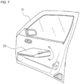
- FIG. 7 is a view illustrating a rotational operation of the mounting board
- FIG. 8 is a view illustrating a state in which the airbag cushion is inflated and expanded in the airbag apparatus for the vehicle according to the present invention.
- the mounting board 20 may be installed to rotate about a shaft coupled to the door 10 in forward and backward directions, so that a rider sitting on the seat can adjust an angle of the mounting board 20 in the forward and backward directions.
- a motor (not shown) may be installed inside the door 10 to generate a driving force to rotate the shaft on which the mounting board 20 is installed.
- a controller for controlling driving of the airbag module 30 may control the motor to rotate in a forward or reverse direction and to adjust the angle of the mounting board 20.
- the present invention may be configured to rotate the mounting board by manipulation of the rider without using a separate motor.
- the airbag module 20 may be installed on the mounting board 20 which is expanded from the door 10 toward the front of the rider in a horizontal direction, and may be inflated and expanded between a frontal airbag cushion 31 and the rider when the vehicle collides, and may restrain and safely protect the rider along with the front airbag cushion 31.
- the airbag module 30 may be inflated and expanded from an inner side end of the mounting board 20 to protect the side of the rider.
- the airbag module 30 may be installed inside or under the mounting board 20, and may be inflated and expanded toward rider's abdomen and may restrain the rider's abdomen when the vehicle collides.
- the frontal airbag cushion 30 may be inflated and expanded from the mounting board 20 toward the rider's abdomen or lower body, and may restrain the rider's abdomen or lower body, first, when the vehicle collides.
- the present invention inflates and expands the airbag cushion at the time of initial collision, and restrains the rider not to move toward the front of the vehicle, so that a collision between the rider and the vehicle caused by the movement of the rider can be prevented in advance.
- the mounting board 20 is installed to be expanded from the door 10 toward the front of the rider, the present invention is not necessarily limited thereto.
- FIGS. 9 and 10 are views illustrating a mounting board according to another embodiment of the present invention.
- Views (a) and (b) of FIG. 9 illustrate a state in which the mounting board is expanded from a seat toward the side of a rider
- views (a) and (b) of FIG. 10 illustrate a state in which the mounting board is expanded from a seat towards the side and the front of a rider.
- the mounting board 20 may be installed on one side of the back or left plate of the seat 11, and may be installed to be expanded toward the side of the rider.
- the mounting board 20 may be installed to protrude from a side surface of the seat 11, or the mounting board being received in the seat 11 may be expanded toward outside of the seat 11 to perform an armrest function.
- the mounting board 20 may be expanded toward the side and the front of the rider in the shape of 'L' when viewed from above, and may perform an armrest function and a function of the mounting board.
- the mounting board 20 may rotate in the horizontal direction along with the seat when the seat 11 is rotated by the rider.
- the mounting board 20 may be installed to have a second holding member 26 rotate in the horizontal direction or vertical direction with reference to a first holding member 25 which functions as an armrest.
- the mounting board 20 may be rotatably installed to be able to adjust an angle with reference to a portion connected to the seat 11 according to a posture of the rider.
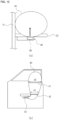
- FIGS. 11 and 12 are views illustrating a configuration of an airbag apparatus for a vehicle according to a first embodiment of the present invention.
- Views (a) and (b) of FIG. 11 are a front view and a side view illustrating a state in which the airbag module embedded in the mounting board is expanded
- views (a) and (b) of FIG. 12 are a front view and a side view illustrating a state in which the airbag module is expanded under the mounting board.
- the airbag module 30 according to the first embodiment of the present invention may be embedded in the mounting board 20 to be invisible from the outside when the mounting board is thicker than a thickness of the airbag module 30 as shown in views (a) and (b) of FIG. 11 .
- An airbag cushion 40 may protrude toward the outside of the mounting board 20 through a tear line formed on an upper surface, a rear surface, or a side surface of the mounting board 32, and may be inflated and expanded toward the front of the rider.
- the airbag module 30 may be installed on a lower surface of the mounting board 20 that has a thin thickness as shown in views (a) and (b) of FIG. 12 .
- the present invention may inflate the airbag cushion 40 of the airbag module 30 installed on the mounting board 20 towards rider's abdomen, and then, may inflate and expand the airbag cushion upwardly to protect the front of rider's abdomen, lower body, and chest.
- the airbag module 30 may include the airbag cushion 40 which is supplied with a gas and is inflated and expanded toward the rider, and an inflator 50 which generates a gas by an ignition signal and supplies the generated gas to the airbag cushion 40.
- the airbag cushion 40 and the inflator 50 of the airbag module 30 may be embedded in the mounting board 20 or installed on the lower surface of the mounting board 20, while being received in a separate housing.
- the airbag cushion 40 may be inflated and expanded to cover from rider's abdomen to rider's head, or may be inflated and expanded to cover from rider's lower body to rider's chest or head.
- the airbag cushion 40 may be formed to be extendable to rider's lower body and chest or head from rider's abdomen.
- the airbag cushion 40 may be formed to have an expansion thickness gradually increase from a lower end to an upper end (d1 ⁇ d2), and to achieve this, one or more tethers 41, 42 may be installed in the airbag cushion 40 to adjust an expansion shape of the airbag cushion 40.
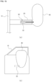
- FIG. 13 is a view illustrating a configuration of an airbag apparatus for a vehicle according to a second embodiment of the present invention.
- Views (a) and (b) of FIG. 13 are a front view and a side view illustrating a state in which the airbag cushion is expanded from a side surface of the mounting board toward the side of a rider.
- the airbag module 30 of the vehicle according to the second embodiment of the present invention is installed on an inner side end of the mounting board 20 as shown in views (a) and (b) of FIG. 13 , that is, on a right side end when viewed on view (a) of FIG. 13 .
- the airbag module 30 of the vehicle inflates and expands the airbag cushion 40 when the vehicle collides, and restrains the inner side of the rider, thereby performing a far side airbag function to protect the inner side of the rider.
- the airbag cushion 40 may be formed to be extendable to cover the side of rider's lower body and chest or head with reference to rider's abdomen.
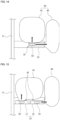
- FIGS. 14 and 15 are views illustrating a configuration of an airbag apparatus for a vehicle according to a third embodiment of the present invention.
- the airbag cushion expanded toward the front of the rider is referred to as a first airbag cushion 43
- the airbag cushion expanded toward the inner side of the rider is referred to as a second airbag cushion 44.
- the airbag module 30 of the vehicle includes the first and second airbag cushions 43, 44 installed on a center and an inner side end of the mounting board 20, respectively, which is expanded from the door 10 toward the front of the rider in a horizontal direction.
- first and second airbag cushions 43, 44 may be supplied with a gas from one inflator 50, or may be supplied with a gas from each of the two inflators 50 to correspond to the first and second airbag cushions 43, 44 as shown in FIG. 15 .
- the present invention may be changed to form the first and second airbag cushions 43, 44 as a plurality of chambers, and to apply a plurality of inflators 50.
- the controller may transmit an ignition signal only to some of the plurality of inflators 50 according to a direction of a collision of the vehicle, and may control only one of the first and second airbag cushions 43, 44 to be selectively inflated and expanded.
- the first airbag cushion 43 may be formed to be extendable to rider's lower body and chest or head from rider's abdomen.
- the second airbag cushion 44 may be formed to be extendable to cover the side of rider's lower body and chest or head from rider's abdomen.
- FIGS. 16 and 17 are views illustrating an expansion state of an airbag cushion in an airbag apparatus for a vehicle according to a fourth embodiment of the present invention.
- View (a) of FIG. 17 illustrates a flap member surrounding the outside of the airbag cushion
- view (b) of FIG. 17 illustrates a state in which the airbag cushion and the flap member are expanded.
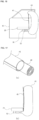
- the airbag cushion 40 in the airbag module 30 of the vehicle according to the fourth embodiment may be inflated and expanded in a curved shape of substantially ')' when viewed from the side, so that a book or an object held on the mounting board 20 can be prevented from flying toward the rider when the airbag cushion 40 is expanded.
- a tether 41 may be installed between an upper end of the airbag cushion 40 and the mounting board 20 to adjust an expansion shape of the airbag cushion 40.
- the present invention inflates and expands the airbag cushion toward the front of the rider, thereby preventing an injury of the rider caused by a flying object from the mounting board.
- the airbag module in the fourth embodiment of the present invention can prevent an object on the mounting board from flying by using the flap member 45 surrounding the outside of the airbag cushion 40 which is in a folding or rolling state as shown in view (a) of FIG. 17 .
- the flap member 45 is expanded when the airbag cushion 40 is inflated and expanded as shown in view (b) of FIG. 17 , and may perform a function of absorbing an impact primarily while an object on the mounting board 20 flies.
- the flap member 45 may have a lower end fixed to the mounting board 20, and may be expanded upwardly when the airbag cushion 40 is expanded.
- Such a flap member 45 may be installed not only on the first airbag cushion 41 corresponding to the front of the rider, but also on the second airbag cushion 42 to prevent an injury of another rider.
- the present invention can prevent an injury of a rider by absorbing an impact of a flying object primarily by using the flap member surrounding the outside of the airbag cushion.
- the present invention can prevent an injury of a rider caused by a flying book or object from the mounting board, by adjusting an expansion shape when the airbag cushion is expanded, or by using the flap member.
- the present invention is not necessarily limited thereto, and may be changed to compensate for a space between a related-art frontal airbag cushion and a rider according to a posture of the rider in a normal vehicle.
- the present invention is applied to airbag technology for a vehicle for safely protecting a rider by expanding an airbag cushion on a mounting board when the vehicle collides.
Landscapes
- Engineering & Computer Science (AREA)
- Mechanical Engineering (AREA)
- Aviation & Aerospace Engineering (AREA)
- Transportation (AREA)
- Physics & Mathematics (AREA)
- Fluid Mechanics (AREA)
- Air Bags (AREA)
Claims (13)
- Véhicule ayant un appareil de coussin de sécurité gonflable, l'appareil de coussin de sécurité gonflable comprenant : un panneau de montage (20) positionné à l'avant d'un usager assis sur un siège (11), dans lequel le panneau de montage (20) est installé pour être déployé à partir d'une portière (10) du véhicule en direction d'un avant de l'usager ou dans lequel le panneau de montage (20) est installé pour être déployé à partir de chaque siège fourni dans le véhicule en direction d'un côté de l'usager, et met en oeuvre une fonction d'accoudoir ou dans lequel le panneau de montage est installé pour être déployé à partir de chaque siège (11) fourni dans le véhicule en direction d'un avant et d'un côté de l'usager, et met en oeuvre une fonction d'accoudoir et une fonction de support ; etun module de coussin de sécurité gonflable (30) installé sur le panneau de montage (20), et conçu pour gonfler et déployer un sac de coussin de sécurité gonflable (40) en direction de l'usager lorsque le véhicule entre en collision, et pour retenir et protéger l'usager, dans lequelle véhicule comprend un coussin de sécurité gonflable frontal (31) etle sac de coussin de sécurité gonflable (40) est gonflé et déployé entre le coussin de sécurité gonflable frontal (31) et l'usager.
- Véhicule selon la revendication 1,
dans lequel le panneau de montage (20) comprend au moins une plaque (21, 22), et est installé sur une surface latérale interne de la portière (10) pour effectuer une rotation dans une direction verticale. - Véhicule selon la revendication 1, dans lequel le panneau de montage (20) est divisé en une pluralité de plaques (21 à 24), et est installé sur une surface latérale interne de la portière (10) pour effectuer une rotation dans une direction verticale, et
dans lequel la pluralité de plaques (21 à 24) coulissent à partir de la portière (10) en direction d'un intérieur du véhicule en séquence et sont déployées en direction de l'avant de l'usager lorsque le panneau de montage (20) est utilisé. - Véhicule selon la revendication 1,dans lequel le panneau de montage (20) est divisé en une pluralité de plaques (21 à 24), etdans lequel la pluralité de plaques (21 à 24) sont reçues à l'intérieur de la portière (10), et coulissent en séquence et sont déployées en direction de l'avant de l'usager lorsque le panneau de montage (20) est utilisé.
- Véhicule selon l'une quelconque des revendications 1 à 4, dans lequel le module de coussin de sécurité gonflable (30) comprend un premier sac de coussin de sécurité gonflable (43) qui est installé sur le panneau de montage (20) et est déployé en direction de l'avant de l'usager, et un gonfleur (50) conçu pour générer un gaz lorsque le véhicule entre en collision et pour alimenter le gaz au sac de coussin de sécurité gonflable (43).
- Véhicule selon l'une quelconque des revendications 1 à 4, dans lequel le module de coussin de sécurité gonflable (30) comprend un second sac de coussin de sécurité gonflable (44) qui est installé sur le panneau de montage (20) et est déployé en direction d'un côté interne de l'usager, et un gonfleur (50) conçu pour générer un gaz lorsque le véhicule entre en collision et pour alimenter le gaz au second sac de coussin de sécurité gonflable (44).
- Véhicule selon l'une quelconque des revendications 1 à 4, dans lequel le module de coussin de sécurité gonflable (30) comprend un premier sac de coussin de sécurité gonflable (43) qui est installé sur le panneau de montage (20) et est déployé en direction de l'avant de l'usager, un second sac de coussin de sécurité gonflable (44) déployé en direction d'un côté interne de l'usager, et un gonfleur (50) conçu pour générer un gaz lorsque le véhicule entre en collision et pour alimenter le gaz aux premier et second coussins de coussin de sécurité gonflable (43, 44).
- Véhicule selon la revendication 7,
dans lequel le premier sac de coussin de sécurité gonflable (43) est gonflé et déployé en direction de l'abdomen ou du bas du corps d'un usager pour retenir l'usager et pour empêcher un mouvement de l'usager au moment d'une collision initiale du véhicule. - Véhicule selon la revendication 7,
dans lequel le premier sac de coussin de sécurité gonflable (40) est formé pour être gonflé et déployé pour s'étendre vers le bas du corps et le thorax ou la tête de l'usager à partir de l'abdomen de l'usager. - Véhicule selon la revendication 7,
dans lequel le second sac de coussin de sécurité gonflable (44) est formé pour être gonflé et déployé pour couvrir un côté du bas du corps et du thorax ou de la tête de l'usager à partir de l'abdomen de l'usager. - Véhicule selon l'une quelconque des revendications 1 à 4,dans lequel le sac de coussin de sécurité gonflable (40) est formé pour avoir une épaisseur de déploiement qui augmente progressivement d'une extrémité inférieure à une extrémité supérieure, etdans lequel un ou plusieurs câbles d'attache (41) sont installés à l'intérieur du sac de coussin de sécurité gonflable (40) pour ajuster une forme de déploiement du sac de coussin de sécurité gonflable (40).
- Véhicule selon l'une quelconque des revendications 1 à 4,dans lequel le sac de coussin de sécurité gonflable (40) est installé sur le panneau de montage (20) dans un état enroulé ou plié, etdans lequel un élément de rabat (45) entourant un extérieur du sac de coussin de sécurité gonflable (40) est déployé en même temps que le sac de coussin de sécurité gonflable (40) pour empêcher un objet sur le panneau de montage (20) de s'envoler.
- Véhicule selon l'une quelconque des revendications 1 à 4,dans lequel le sac de coussin de sécurité gonflable (40) est déployé sous une forme de « ) » en coupe transversale pour empêcher un objet sur le panneau de montage (20) de s'envoler, etdans lequel un câble d'attache (41) est installé entre le panneau de montage (20) et une extrémité supérieure du sac de coussin de sécurité gonflable (40) pour ajuster une forme de déploiement du sac de coussin de sécurité gonflable (40).
Applications Claiming Priority (2)
| Application Number | Priority Date | Filing Date | Title |
|---|---|---|---|
| KR1020180046732A KR102064843B1 (ko) | 2018-04-23 | 2018-04-23 | 자동차의 에어백 장치 |
| PCT/KR2019/003861 WO2019208947A1 (fr) | 2018-04-23 | 2019-04-02 | Appareil de coussin de sécurité gonflable destiné à un véhicule |
Publications (3)
| Publication Number | Publication Date |
|---|---|
| EP3786003A1 EP3786003A1 (fr) | 2021-03-03 |
| EP3786003A4 EP3786003A4 (fr) | 2021-11-24 |
| EP3786003B1 true EP3786003B1 (fr) | 2024-07-24 |
Family
ID=68294134
Family Applications (1)
| Application Number | Title | Priority Date | Filing Date |
|---|---|---|---|
| EP19792081.2A Active EP3786003B1 (fr) | 2018-04-23 | 2019-04-02 | Appareil de coussin de sécurité gonflable destiné à un véhicule |
Country Status (5)
| Country | Link |
|---|---|
| US (1) | US11541837B2 (fr) |
| EP (1) | EP3786003B1 (fr) |
| KR (1) | KR102064843B1 (fr) |
| CN (1) | CN112088114B (fr) |
| WO (1) | WO2019208947A1 (fr) |
Families Citing this family (5)
| Publication number | Priority date | Publication date | Assignee | Title |
|---|---|---|---|---|
| US11364869B1 (en) * | 2021-02-19 | 2022-06-21 | GM Global Technology Operations LLC | Thorax and thigh airbag system for reclined passengers |
| KR20230030876A (ko) * | 2021-08-26 | 2023-03-07 | 현대자동차주식회사 | 파노라믹 윈도우 안전 시스템 및 차량 |
| CN115465218A (zh) * | 2022-09-26 | 2022-12-13 | 恒大恒驰新能源汽车研究院(上海)有限公司 | 车辆及其控制方法 |
| KR102920820B1 (ko) * | 2023-02-08 | 2026-01-30 | 아우토리브 디벨롭먼트 아베 | 자동차의 사이드 에어백 장치 |
| US12330577B2 (en) | 2023-10-12 | 2025-06-17 | Ford Global Technologies, Llc | Armrest pivotably supported by door side panel |
Family Cites Families (36)
| Publication number | Priority date | Publication date | Assignee | Title |
|---|---|---|---|---|
| US5224732A (en) * | 1991-07-16 | 1993-07-06 | Toyota Motor Co Ltd | Inflatable restraint system for side impact crash protection |
| US5746443A (en) * | 1992-07-13 | 1998-05-05 | Joalto Design, Inc. | Side impact air bag deployable between a vehicle body and an occupant |
| DE69532094T2 (de) * | 1994-09-08 | 2004-08-26 | Breed Automotive Technology, Inc., Lakeland | Luftsack zum Schützen von Kraftfahrzeuginsassen |
| US5492361A (en) * | 1995-01-26 | 1996-02-20 | Kim; Ki I. | Side airbag apparatus |
| KR970010318A (ko) * | 1995-08-18 | 1997-03-27 | 배순훈 | 측면 충격력을 완화할 수 있는 자동차용 운전석 팔걸이대 |
| KR19980052800A (ko) | 1996-12-24 | 1998-09-25 | 김광호 | 차량에서 휴대용 컴퓨터의 사용을 가능하게 하는 보조장치 |
| DE10253472A1 (de) * | 2002-11-16 | 2004-06-17 | Acts Gmbh & Co. Kg | Fahrzeugausstattungsanteil mit Airbagmodul |
| JP4172039B2 (ja) * | 2003-03-19 | 2008-10-29 | 関東自動車工業株式会社 | スライドドア用アームレスト装置 |
| US7178827B2 (en) * | 2004-02-10 | 2007-02-20 | Ford Global Technologies, Llc | Occupant ejection prevention assembly |
| EP1577172B1 (fr) * | 2004-03-17 | 2012-11-14 | Takata AG | Dispositif d'airbag |
| KR20060016398A (ko) | 2004-08-17 | 2006-02-22 | 현대모비스 주식회사 | 차량의 시트 벨트구조 |
| FR2876065B1 (fr) * | 2004-10-01 | 2008-02-15 | Peugeot Citroen Automobiles Sa | Porte coulissante pour vehicule automobile |
| JP4556817B2 (ja) * | 2005-09-21 | 2010-10-06 | 豊田合成株式会社 | サイドエアバッグ装置 |
| US7708308B2 (en) * | 2006-10-09 | 2010-05-04 | Delphi Technologies, Inc. | Side airbag cushion and method of manufacture |
| JP5034455B2 (ja) * | 2006-11-24 | 2012-09-26 | マツダ株式会社 | カーテンエアバッグ装置を備えた車両の内装構造 |
| EP2117882B1 (fr) * | 2007-02-14 | 2012-09-19 | Autoliv Development AB | Coussin gonflable pour véhicule à moteur |
| JP2009208566A (ja) * | 2008-03-03 | 2009-09-17 | Nissan Motor Co Ltd | 乗員膝保護装置付き回転テーブル |
| WO2011016107A1 (fr) * | 2009-08-03 | 2011-02-10 | トヨタ自動車株式会社 | Dispositif de coussin de sécurité gonflable latéral pour véhicule |
| US8596673B2 (en) * | 2011-01-31 | 2013-12-03 | Trw Vehicle Safety Systems Inc. | Anti-ejection inflatable vehicle occupant protection device |
| US20130088056A1 (en) * | 2011-10-11 | 2013-04-11 | Zodiac Aerospace | Tubular airbag |
| JP5263367B2 (ja) * | 2011-10-17 | 2013-08-14 | 日産自動車株式会社 | 乗り物の乗員保護装置 |
| JP5776519B2 (ja) * | 2011-11-29 | 2015-09-09 | トヨタ自動車株式会社 | 車両用乗員拘束装置 |
| US8480125B1 (en) * | 2012-02-07 | 2013-07-09 | Ford Global Technologies, Llc | Curtain air bag system |
| DE102014006862B4 (de) * | 2014-05-13 | 2026-02-05 | Zf Automotive Germany Gmbh | Fahrzeuginsassenschutzeinrichtung und Fahrzeugsitz |
| DE102014113277A1 (de) * | 2014-09-15 | 2016-03-17 | Recaro Aircraft Seating Gmbh & Co. Kg | Flugzeugsitzvorrichtung |
| JP6281462B2 (ja) * | 2014-10-02 | 2018-02-21 | トヨタ自動車株式会社 | サイドエアバッグを備えた可動式アームレスト付き車両用シート |
| KR101611087B1 (ko) | 2014-10-23 | 2016-04-11 | 현대자동차주식회사 | 차량용 승객 보호시스템 및 방법 |
| KR101655569B1 (ko) | 2014-11-12 | 2016-09-08 | 현대자동차주식회사 | 차량용 승객 보호시스템 및 방법 |
| US20170210329A1 (en) * | 2016-01-25 | 2017-07-27 | Ford Global Technologies, Llc | Door-mounted airbag assembly |
| KR101836601B1 (ko) * | 2016-03-04 | 2018-03-09 | 기아자동차주식회사 | 차량용 커튼 에어백 |
| DE112019001626A5 (de) * | 2018-03-27 | 2020-12-24 | Joyson Safety Systems Germany Gmbh | Gassackanordnung für ein fahrzeuginsassen-rückhaltesystem |
| US10759376B2 (en) * | 2018-08-06 | 2020-09-01 | Ford Global Technologies, Llc | Vehicle airbag |
| WO2020085304A1 (fr) * | 2018-10-23 | 2020-04-30 | テイ・エス テック株式会社 | Dispositif de protection d'occupant |
| CN109398049B (zh) * | 2018-10-30 | 2020-06-09 | 北京汽车研究总院有限公司 | 一种车门扶手和具有其的车辆 |
| KR102088495B1 (ko) * | 2020-01-29 | 2020-03-13 | 덕양산업 주식회사 | 도어 트림 |
| DE102020118337A1 (de) * | 2020-07-10 | 2022-01-13 | Zf Automotive Germany Gmbh | Fahrzeuginsassenrückhaltesystem |
-
2018
- 2018-04-23 KR KR1020180046732A patent/KR102064843B1/ko active Active
-
2019
- 2019-04-02 CN CN201980029727.3A patent/CN112088114B/zh active Active
- 2019-04-02 WO PCT/KR2019/003861 patent/WO2019208947A1/fr not_active Ceased
- 2019-04-02 EP EP19792081.2A patent/EP3786003B1/fr active Active
- 2019-04-02 US US17/049,501 patent/US11541837B2/en active Active
Also Published As
| Publication number | Publication date |
|---|---|
| US20210253054A1 (en) | 2021-08-19 |
| KR102064843B1 (ko) | 2020-01-10 |
| KR20190123051A (ko) | 2019-10-31 |
| US11541837B2 (en) | 2023-01-03 |
| EP3786003A1 (fr) | 2021-03-03 |
| WO2019208947A1 (fr) | 2019-10-31 |
| EP3786003A4 (fr) | 2021-11-24 |
| CN112088114B (zh) | 2022-11-15 |
| CN112088114A (zh) | 2020-12-15 |
Similar Documents
| Publication | Publication Date | Title |
|---|---|---|
| EP3786003B1 (fr) | Appareil de coussin de sécurité gonflable destiné à un véhicule | |
| US11312326B2 (en) | Airbag device for vehicle | |
| US10272865B2 (en) | Arm rest | |
| KR102154182B1 (ko) | 자동차의 에어백 장치 | |
| KR102005746B1 (ko) | 자율주행 자동차의 에어백 장치 | |
| CN110770073B (zh) | 车辆座椅 | |
| KR20200130765A (ko) | 자동차의 에어백 장치 | |
| KR102154195B1 (ko) | 자동차의 에어백 장치 | |
| KR102755190B1 (ko) | 자동차의 에어백 장치 | |
| EP4212396B1 (fr) | Dispositif coussin de sécurité gonflable pour véhicule | |
| KR102729837B1 (ko) | 자동차의 에어백 장치 | |
| CN110325408A (zh) | 车辆乘员约束设备和用于运行车辆乘员约束设备的方法 | |
| US20150274113A1 (en) | Airbag device | |
| GB2542936A (en) | Airbag assembly including depressed region below steering column | |
| KR102167457B1 (ko) | 자동차의 에어백 장치 | |
| KR102167448B1 (ko) | 자동차의 에어백 장치 | |
| KR20220033084A (ko) | 자동차의 에어백 장치 | |
| KR20210002883A (ko) | 자동차의 에어백 장치 | |
| EP3932753B1 (fr) | Dispositif de coussin gonflable de sécurité de véhicule | |
| EP4534361A1 (fr) | Dispositif de coussin de sécurité gonflable de véhicule | |
| KR102300446B1 (ko) | 자동차의 에어백 장치 | |
| KR20240071862A (ko) | 자동차의 에어백 장치 |
Legal Events
| Date | Code | Title | Description |
|---|---|---|---|
| STAA | Information on the status of an ep patent application or granted ep patent |
Free format text: STATUS: THE INTERNATIONAL PUBLICATION HAS BEEN MADE |
|
| PUAI | Public reference made under article 153(3) epc to a published international application that has entered the european phase |
Free format text: ORIGINAL CODE: 0009012 |
|
| STAA | Information on the status of an ep patent application or granted ep patent |
Free format text: STATUS: REQUEST FOR EXAMINATION WAS MADE |
|
| 17P | Request for examination filed |
Effective date: 20201111 |
|
| AK | Designated contracting states |
Kind code of ref document: A1 Designated state(s): AL AT BE BG CH CY CZ DE DK EE ES FI FR GB GR HR HU IE IS IT LI LT LU LV MC MK MT NL NO PL PT RO RS SE SI SK SM TR |
|
| AX | Request for extension of the european patent |
Extension state: BA ME |
|
| DAV | Request for validation of the european patent (deleted) | ||
| DAX | Request for extension of the european patent (deleted) | ||
| A4 | Supplementary search report drawn up and despatched |
Effective date: 20211022 |
|
| RIC1 | Information provided on ipc code assigned before grant |
Ipc: B60N 2/75 20180101ALI20211018BHEP Ipc: B60R 21/2338 20110101ALI20211018BHEP Ipc: B60R 21/231 20110101ALI20211018BHEP Ipc: B60R 21/264 20060101ALI20211018BHEP Ipc: B60R 21/21 20110101AFI20211018BHEP |
|
| STAA | Information on the status of an ep patent application or granted ep patent |
Free format text: STATUS: EXAMINATION IS IN PROGRESS |
|
| 17Q | First examination report despatched |
Effective date: 20230322 |
|
| GRAP | Despatch of communication of intention to grant a patent |
Free format text: ORIGINAL CODE: EPIDOSNIGR1 |
|
| STAA | Information on the status of an ep patent application or granted ep patent |
Free format text: STATUS: GRANT OF PATENT IS INTENDED |
|
| INTG | Intention to grant announced |
Effective date: 20240516 |
|
| GRAS | Grant fee paid |
Free format text: ORIGINAL CODE: EPIDOSNIGR3 |
|
| GRAA | (expected) grant |
Free format text: ORIGINAL CODE: 0009210 |
|
| STAA | Information on the status of an ep patent application or granted ep patent |
Free format text: STATUS: THE PATENT HAS BEEN GRANTED |
|
| AK | Designated contracting states |
Kind code of ref document: B1 Designated state(s): AL AT BE BG CH CY CZ DE DK EE ES FI FR GB GR HR HU IE IS IT LI LT LU LV MC MK MT NL NO PL PT RO RS SE SI SK SM TR |
|
| REG | Reference to a national code |
Ref country code: GB Ref legal event code: FG4D |
|
| REG | Reference to a national code |
Ref country code: CH Ref legal event code: EP |
|
| REG | Reference to a national code |
Ref country code: DE Ref legal event code: R096 Ref document number: 602019055790 Country of ref document: DE |
|
| REG | Reference to a national code |
Ref country code: IE Ref legal event code: FG4D |
|
| REG | Reference to a national code |
Ref country code: LT Ref legal event code: MG9D |
|
| REG | Reference to a national code |
Ref country code: NL Ref legal event code: MP Effective date: 20240724 |
|
| PG25 | Lapsed in a contracting state [announced via postgrant information from national office to epo] |
Ref country code: PT Free format text: LAPSE BECAUSE OF FAILURE TO SUBMIT A TRANSLATION OF THE DESCRIPTION OR TO PAY THE FEE WITHIN THE PRESCRIBED TIME-LIMIT Effective date: 20241125 |
|
| REG | Reference to a national code |
Ref country code: AT Ref legal event code: MK05 Ref document number: 1706038 Country of ref document: AT Kind code of ref document: T Effective date: 20240724 |
|
| PG25 | Lapsed in a contracting state [announced via postgrant information from national office to epo] |
Ref country code: NL Free format text: LAPSE BECAUSE OF FAILURE TO SUBMIT A TRANSLATION OF THE DESCRIPTION OR TO PAY THE FEE WITHIN THE PRESCRIBED TIME-LIMIT Effective date: 20240724 |
|
| PG25 | Lapsed in a contracting state [announced via postgrant information from national office to epo] |
Ref country code: PT Free format text: LAPSE BECAUSE OF FAILURE TO SUBMIT A TRANSLATION OF THE DESCRIPTION OR TO PAY THE FEE WITHIN THE PRESCRIBED TIME-LIMIT Effective date: 20241125 Ref country code: NL Free format text: LAPSE BECAUSE OF FAILURE TO SUBMIT A TRANSLATION OF THE DESCRIPTION OR TO PAY THE FEE WITHIN THE PRESCRIBED TIME-LIMIT Effective date: 20240724 |
|
| PG25 | Lapsed in a contracting state [announced via postgrant information from national office to epo] |
Ref country code: NO Free format text: LAPSE BECAUSE OF FAILURE TO SUBMIT A TRANSLATION OF THE DESCRIPTION OR TO PAY THE FEE WITHIN THE PRESCRIBED TIME-LIMIT Effective date: 20241024 |
|
| PG25 | Lapsed in a contracting state [announced via postgrant information from national office to epo] |
Ref country code: GR Free format text: LAPSE BECAUSE OF FAILURE TO SUBMIT A TRANSLATION OF THE DESCRIPTION OR TO PAY THE FEE WITHIN THE PRESCRIBED TIME-LIMIT Effective date: 20241025 Ref country code: PL Free format text: LAPSE BECAUSE OF FAILURE TO SUBMIT A TRANSLATION OF THE DESCRIPTION OR TO PAY THE FEE WITHIN THE PRESCRIBED TIME-LIMIT Effective date: 20240724 Ref country code: FI Free format text: LAPSE BECAUSE OF FAILURE TO SUBMIT A TRANSLATION OF THE DESCRIPTION OR TO PAY THE FEE WITHIN THE PRESCRIBED TIME-LIMIT Effective date: 20240724 |
|
| PG25 | Lapsed in a contracting state [announced via postgrant information from national office to epo] |
Ref country code: BG Free format text: LAPSE BECAUSE OF FAILURE TO SUBMIT A TRANSLATION OF THE DESCRIPTION OR TO PAY THE FEE WITHIN THE PRESCRIBED TIME-LIMIT Effective date: 20240724 |
|
| PG25 | Lapsed in a contracting state [announced via postgrant information from national office to epo] |
Ref country code: LV Free format text: LAPSE BECAUSE OF FAILURE TO SUBMIT A TRANSLATION OF THE DESCRIPTION OR TO PAY THE FEE WITHIN THE PRESCRIBED TIME-LIMIT Effective date: 20240724 |
|
| PG25 | Lapsed in a contracting state [announced via postgrant information from national office to epo] |
Ref country code: IS Free format text: LAPSE BECAUSE OF FAILURE TO SUBMIT A TRANSLATION OF THE DESCRIPTION OR TO PAY THE FEE WITHIN THE PRESCRIBED TIME-LIMIT Effective date: 20241124 Ref country code: AT Free format text: LAPSE BECAUSE OF FAILURE TO SUBMIT A TRANSLATION OF THE DESCRIPTION OR TO PAY THE FEE WITHIN THE PRESCRIBED TIME-LIMIT Effective date: 20240724 |
|
| PG25 | Lapsed in a contracting state [announced via postgrant information from national office to epo] |
Ref country code: HR Free format text: LAPSE BECAUSE OF FAILURE TO SUBMIT A TRANSLATION OF THE DESCRIPTION OR TO PAY THE FEE WITHIN THE PRESCRIBED TIME-LIMIT Effective date: 20240724 |
|
| PG25 | Lapsed in a contracting state [announced via postgrant information from national office to epo] |
Ref country code: RS Free format text: LAPSE BECAUSE OF FAILURE TO SUBMIT A TRANSLATION OF THE DESCRIPTION OR TO PAY THE FEE WITHIN THE PRESCRIBED TIME-LIMIT Effective date: 20241024 Ref country code: ES Free format text: LAPSE BECAUSE OF FAILURE TO SUBMIT A TRANSLATION OF THE DESCRIPTION OR TO PAY THE FEE WITHIN THE PRESCRIBED TIME-LIMIT Effective date: 20240724 |
|
| PG25 | Lapsed in a contracting state [announced via postgrant information from national office to epo] |
Ref country code: RS Free format text: LAPSE BECAUSE OF FAILURE TO SUBMIT A TRANSLATION OF THE DESCRIPTION OR TO PAY THE FEE WITHIN THE PRESCRIBED TIME-LIMIT Effective date: 20241024 Ref country code: PL Free format text: LAPSE BECAUSE OF FAILURE TO SUBMIT A TRANSLATION OF THE DESCRIPTION OR TO PAY THE FEE WITHIN THE PRESCRIBED TIME-LIMIT Effective date: 20240724 Ref country code: NO Free format text: LAPSE BECAUSE OF FAILURE TO SUBMIT A TRANSLATION OF THE DESCRIPTION OR TO PAY THE FEE WITHIN THE PRESCRIBED TIME-LIMIT Effective date: 20241024 Ref country code: LV Free format text: LAPSE BECAUSE OF FAILURE TO SUBMIT A TRANSLATION OF THE DESCRIPTION OR TO PAY THE FEE WITHIN THE PRESCRIBED TIME-LIMIT Effective date: 20240724 Ref country code: IS Free format text: LAPSE BECAUSE OF FAILURE TO SUBMIT A TRANSLATION OF THE DESCRIPTION OR TO PAY THE FEE WITHIN THE PRESCRIBED TIME-LIMIT Effective date: 20241124 Ref country code: HR Free format text: LAPSE BECAUSE OF FAILURE TO SUBMIT A TRANSLATION OF THE DESCRIPTION OR TO PAY THE FEE WITHIN THE PRESCRIBED TIME-LIMIT Effective date: 20240724 Ref country code: GR Free format text: LAPSE BECAUSE OF FAILURE TO SUBMIT A TRANSLATION OF THE DESCRIPTION OR TO PAY THE FEE WITHIN THE PRESCRIBED TIME-LIMIT Effective date: 20241025 Ref country code: FI Free format text: LAPSE BECAUSE OF FAILURE TO SUBMIT A TRANSLATION OF THE DESCRIPTION OR TO PAY THE FEE WITHIN THE PRESCRIBED TIME-LIMIT Effective date: 20240724 Ref country code: ES Free format text: LAPSE BECAUSE OF FAILURE TO SUBMIT A TRANSLATION OF THE DESCRIPTION OR TO PAY THE FEE WITHIN THE PRESCRIBED TIME-LIMIT Effective date: 20240724 Ref country code: BG Free format text: LAPSE BECAUSE OF FAILURE TO SUBMIT A TRANSLATION OF THE DESCRIPTION OR TO PAY THE FEE WITHIN THE PRESCRIBED TIME-LIMIT Effective date: 20240724 Ref country code: AT Free format text: LAPSE BECAUSE OF FAILURE TO SUBMIT A TRANSLATION OF THE DESCRIPTION OR TO PAY THE FEE WITHIN THE PRESCRIBED TIME-LIMIT Effective date: 20240724 |
|
| PG25 | Lapsed in a contracting state [announced via postgrant information from national office to epo] |
Ref country code: SM Free format text: LAPSE BECAUSE OF FAILURE TO SUBMIT A TRANSLATION OF THE DESCRIPTION OR TO PAY THE FEE WITHIN THE PRESCRIBED TIME-LIMIT Effective date: 20240724 Ref country code: DK Free format text: LAPSE BECAUSE OF FAILURE TO SUBMIT A TRANSLATION OF THE DESCRIPTION OR TO PAY THE FEE WITHIN THE PRESCRIBED TIME-LIMIT Effective date: 20240724 Ref country code: RO Free format text: LAPSE BECAUSE OF FAILURE TO SUBMIT A TRANSLATION OF THE DESCRIPTION OR TO PAY THE FEE WITHIN THE PRESCRIBED TIME-LIMIT Effective date: 20240724 |
|
| PG25 | Lapsed in a contracting state [announced via postgrant information from national office to epo] |
Ref country code: EE Free format text: LAPSE BECAUSE OF FAILURE TO SUBMIT A TRANSLATION OF THE DESCRIPTION OR TO PAY THE FEE WITHIN THE PRESCRIBED TIME-LIMIT Effective date: 20240724 |
|
| PG25 | Lapsed in a contracting state [announced via postgrant information from national office to epo] |
Ref country code: CZ Free format text: LAPSE BECAUSE OF FAILURE TO SUBMIT A TRANSLATION OF THE DESCRIPTION OR TO PAY THE FEE WITHIN THE PRESCRIBED TIME-LIMIT Effective date: 20240724 |
|
| REG | Reference to a national code |
Ref country code: DE Ref legal event code: R097 Ref document number: 602019055790 Country of ref document: DE |
|
| PG25 | Lapsed in a contracting state [announced via postgrant information from national office to epo] |
Ref country code: SK Free format text: LAPSE BECAUSE OF FAILURE TO SUBMIT A TRANSLATION OF THE DESCRIPTION OR TO PAY THE FEE WITHIN THE PRESCRIBED TIME-LIMIT Effective date: 20240724 Ref country code: IT Free format text: LAPSE BECAUSE OF FAILURE TO SUBMIT A TRANSLATION OF THE DESCRIPTION OR TO PAY THE FEE WITHIN THE PRESCRIBED TIME-LIMIT Effective date: 20240724 |
|
| PLBE | No opposition filed within time limit |
Free format text: ORIGINAL CODE: 0009261 |
|
| STAA | Information on the status of an ep patent application or granted ep patent |
Free format text: STATUS: NO OPPOSITION FILED WITHIN TIME LIMIT |
|
| 26N | No opposition filed |
Effective date: 20250425 |
|
| PGFP | Annual fee paid to national office [announced via postgrant information from national office to epo] |
Ref country code: DE Payment date: 20250428 Year of fee payment: 7 |
|
| PGFP | Annual fee paid to national office [announced via postgrant information from national office to epo] |
Ref country code: GB Payment date: 20250422 Year of fee payment: 7 |
|
| PGFP | Annual fee paid to national office [announced via postgrant information from national office to epo] |
Ref country code: FR Payment date: 20250424 Year of fee payment: 7 |
|
| PG25 | Lapsed in a contracting state [announced via postgrant information from national office to epo] |
Ref country code: SE Free format text: LAPSE BECAUSE OF FAILURE TO SUBMIT A TRANSLATION OF THE DESCRIPTION OR TO PAY THE FEE WITHIN THE PRESCRIBED TIME-LIMIT Effective date: 20240724 |
|
| REG | Reference to a national code |
Ref country code: CH Ref legal event code: H13 Free format text: ST27 STATUS EVENT CODE: U-0-0-H10-H13 (AS PROVIDED BY THE NATIONAL OFFICE) Effective date: 20251125 |
|
| PG25 | Lapsed in a contracting state [announced via postgrant information from national office to epo] |
Ref country code: LU Free format text: LAPSE BECAUSE OF NON-PAYMENT OF DUE FEES Effective date: 20250402 |
|
| PG25 | Lapsed in a contracting state [announced via postgrant information from national office to epo] |
Ref country code: MC Free format text: LAPSE BECAUSE OF FAILURE TO SUBMIT A TRANSLATION OF THE DESCRIPTION OR TO PAY THE FEE WITHIN THE PRESCRIBED TIME-LIMIT Effective date: 20240724 |
|
| REG | Reference to a national code |
Ref country code: BE Ref legal event code: MM Effective date: 20250430 |
|
| PG25 | Lapsed in a contracting state [announced via postgrant information from national office to epo] |
Ref country code: BE Free format text: LAPSE BECAUSE OF NON-PAYMENT OF DUE FEES Effective date: 20250430 |
|
| PG25 | Lapsed in a contracting state [announced via postgrant information from national office to epo] |
Ref country code: CH Free format text: LAPSE BECAUSE OF NON-PAYMENT OF DUE FEES Effective date: 20250430 |
|
| PG25 | Lapsed in a contracting state [announced via postgrant information from national office to epo] |
Ref country code: IE Free format text: LAPSE BECAUSE OF NON-PAYMENT OF DUE FEES Effective date: 20250402 |