EP3786100B1 - Drehkranzkran mit begrenzter rotation - Google Patents
Drehkranzkran mit begrenzter rotation Download PDFInfo
- Publication number
- EP3786100B1 EP3786100B1 EP20185576.4A EP20185576A EP3786100B1 EP 3786100 B1 EP3786100 B1 EP 3786100B1 EP 20185576 A EP20185576 A EP 20185576A EP 3786100 B1 EP3786100 B1 EP 3786100B1
- Authority
- EP
- European Patent Office
- Prior art keywords
- respect
- wheel
- pedestal
- stationary body
- slewing ring
- Prior art date
- Legal status (The legal status is an assumption and is not a legal conclusion. Google has not performed a legal analysis and makes no representation as to the accuracy of the status listed.)
- Active
Links
Images


Classifications
-
- B—PERFORMING OPERATIONS; TRANSPORTING
- B66—HOISTING; LIFTING; HAULING
- B66C—CRANES; LOAD-ENGAGING ELEMENTS OR DEVICES FOR CRANES, CAPSTANS, WINCHES, OR TACKLES
- B66C23/00—Cranes comprising essentially a beam, boom, or triangular structure acting as a cantilever and mounted for translatory of swinging movements in vertical or horizontal planes or a combination of such movements, e.g. jib-cranes, derricks, tower cranes
- B66C23/88—Safety gear
- B66C23/94—Safety gear for limiting slewing movements
-
- B—PERFORMING OPERATIONS; TRANSPORTING
- B66—HOISTING; LIFTING; HAULING
- B66C—CRANES; LOAD-ENGAGING ELEMENTS OR DEVICES FOR CRANES, CAPSTANS, WINCHES, OR TACKLES
- B66C13/00—Other constructional features or details
- B66C13/18—Control systems or devices
- B66C13/46—Position indicators for suspended loads or for crane elements
-
- B—PERFORMING OPERATIONS; TRANSPORTING
- B66—HOISTING; LIFTING; HAULING
- B66C—CRANES; LOAD-ENGAGING ELEMENTS OR DEVICES FOR CRANES, CAPSTANS, WINCHES, OR TACKLES
- B66C23/00—Cranes comprising essentially a beam, boom, or triangular structure acting as a cantilever and mounted for translatory of swinging movements in vertical or horizontal planes or a combination of such movements, e.g. jib-cranes, derricks, tower cranes
- B66C23/16—Cranes comprising essentially a beam, boom, or triangular structure acting as a cantilever and mounted for translatory of swinging movements in vertical or horizontal planes or a combination of such movements, e.g. jib-cranes, derricks, tower cranes with jibs supported by columns, e.g. towers having their lower end mounted for slewing movements
- B66C23/163—Cranes comprising essentially a beam, boom, or triangular structure acting as a cantilever and mounted for translatory of swinging movements in vertical or horizontal planes or a combination of such movements, e.g. jib-cranes, derricks, tower cranes with jibs supported by columns, e.g. towers having their lower end mounted for slewing movements where only part of the column rotates, i.e. at least the bottom part is fixed
-
- B—PERFORMING OPERATIONS; TRANSPORTING
- B66—HOISTING; LIFTING; HAULING
- B66C—CRANES; LOAD-ENGAGING ELEMENTS OR DEVICES FOR CRANES, CAPSTANS, WINCHES, OR TACKLES
- B66C23/00—Cranes comprising essentially a beam, boom, or triangular structure acting as a cantilever and mounted for translatory of swinging movements in vertical or horizontal planes or a combination of such movements, e.g. jib-cranes, derricks, tower cranes
- B66C23/18—Cranes comprising essentially a beam, boom, or triangular structure acting as a cantilever and mounted for translatory of swinging movements in vertical or horizontal planes or a combination of such movements, e.g. jib-cranes, derricks, tower cranes specially adapted for use in particular purposes
- B66C23/36—Cranes comprising essentially a beam, boom, or triangular structure acting as a cantilever and mounted for translatory of swinging movements in vertical or horizontal planes or a combination of such movements, e.g. jib-cranes, derricks, tower cranes specially adapted for use in particular purposes mounted on road or rail vehicles; Manually-movable jib-cranes for use in workshops; Floating cranes
- B66C23/42—Cranes comprising essentially a beam, boom, or triangular structure acting as a cantilever and mounted for translatory of swinging movements in vertical or horizontal planes or a combination of such movements, e.g. jib-cranes, derricks, tower cranes specially adapted for use in particular purposes mounted on road or rail vehicles; Manually-movable jib-cranes for use in workshops; Floating cranes with jibs of adjustable configuration, e.g. foldable
-
- B—PERFORMING OPERATIONS; TRANSPORTING
- B66—HOISTING; LIFTING; HAULING
- B66C—CRANES; LOAD-ENGAGING ELEMENTS OR DEVICES FOR CRANES, CAPSTANS, WINCHES, OR TACKLES
- B66C23/00—Cranes comprising essentially a beam, boom, or triangular structure acting as a cantilever and mounted for translatory of swinging movements in vertical or horizontal planes or a combination of such movements, e.g. jib-cranes, derricks, tower cranes
- B66C23/62—Constructional features or details
- B66C23/84—Slewing gear
Definitions
- the present invention refers to a limited rotation slewing ring crane, particularly a limited rotation slewing ring crane provided with a sensor of the rotation of the column with respect to the pedestal.
- Slewing ring cranes are a particular type of loading cranes, which differ from the rack cranes by the way the column and pedestal are rotatively coupled to each other.
- the slewing ring cranes comprise a bearing coupling (the slewing ring) for providing such relative rotation.
- the slewing ring cranes in comparison with the rack cranes, although are structurally complex, provide more power to the rotation.
- the slewing ring cranes are divided in unlimited rotation slewing ring cranes and limited rotation slewing ring cranes.
- the first ones are characterized by the fact that the column rotation with respect to the pedestal is unlimited, while the second ones are provided with stop elements limiting the rotation arc of the column with respect to the pedestal.
- the unlimited slewing ring cranes are structurally more complex than the limited rotation slewing ring cranes because the former require the presence of electric and hydraulic joints at the rotative coupling between the column and pedestal which are arranged in order to prevent the hydraulic pipes and electric cables from twisting due to the potentially unlimited rotations of the column with respect to the pedestal.
- the limited rotation slewing ring cranes do not have this problem, consequently they do not require hydraulic and electric joints.
- Loading cranes are provided with multiple sensors, which are required for supplying a measurement of magnitudes representative of the state of the crane, and consequently, ultimately, for enabling an effective operation.
- One of the required sensors is the rotation sensor apt to measure the rotations of the column with respect to the pedestal.
- an object of the present invention is to provide a limited rotation slewing ring crane equipped with a sensor of the rotation of the column with respect to the pedestal which is a structurally simplified and less expensive alternative to the solution provided in the unlimited slewing ring cranes.
- a limited slewing ring crane comprising a pedestal, a column rotatively coupled, about a first rotation axis, to the pedestal by a slewing ring rotative coupling, and means for limiting the relative rotation of the column with respect to the pedestal, further comprising a rotative sensor adapted to measure a rotation angle of the column with respect to the pedestal, wherein said rotation sensor comprises:
- reference 1 generally indicates a limited rotation slewing ring crane.
- the crane 1 comprises a column 2 rotating about a rotation axis with respect to a pedestal 3, and one or more arms 4', 4", eventually of the extendable type.
- the extendibility of the arms is obtained by a plurality of extensions 5 translatingly movable from each other, operated by hydraulic actuators, in order to vary the axial extension of a corresponding arm.
- only the second arm 4" is extendable by moving the extensions 5.
- the base of the column 2 is rotatively coupled to the pedestal 3 by a rotative coupling 6 comprising a slewing ring 7.
- slewing ring means an axial bearing particularly adapted to operate at low rotation speeds and with high axial loads, comprising an inner crown and outer crown coupled by one or more crowns of balls or rolls such to enable the relative rotations.
- base indicates the portion of the column 2 proximate to the pedestal 3, in other words the lower portion of the column 2, with reference to the normal conditions of use of crane 1.
- the crane 1 comprises means for limiting the relative rotation of the column 2 with respect to the pedestal 3.
- the rotative coupling 6 can comprise one or more mechanical stop elements capable of limiting the relative rotation of the column 2 with respect to the pedestal 3.
- such mechanical stop elements comprise a crescent-shaped slot 8, preferably made in the pedestal 3, and at least one pin 9, preferably associated to the column 2, parallel to and radially distanced from the rotation axis of this latter, sliding inside said slot 8. Constraining the pin 9 to slide inside the slot 8 limits the angular amplitude of the column 2 rotation with respect to the pedestal 3.
- the column 2 rotation with respect to the pedestal 3 can be electronically limited, for example by shutting off the supply to the crane 2 if the column relative rotation preset limits 2 with respect to the pedestal 3 are exceeded.
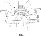
- the crane 1 comprises a rotative sensor 10 adapted to measure a rotation angle of the column 2 with respect to the pedestal 3, of which a description according to some possible embodiments of the invention will be provided. It is observed that such rotative sensor 10 can also be used for monitoring if the position of the column 2 falls inside preset rotation limits with respect to the pedestal if the mechanical stop elements are not provided.
- such rotative sensor 10 comprises a tubular body 11 placed at the base of the column 2 and axially protruding from the same preferably towards the inside of the pedestal 3 (in other words towards the ground, with reference to the normal conditions of use of the crane 1).
- the tubular body 11 is rotatively integral with the column 2.
- the tubular body 11 is made by a piece distinct from the column 2 and is fixedly connected to the latter. It is observed that the electric cables and hydraulic pipes (not shown in the figures) extend through the tubular shape of the tubular body 11 towards the crane arms.
- auxiliary crown 12 is made of a deformable material, wherein the term "deformable" does not mean a deformation of a limited amount, such as the one affecting a rigid material for example (such as a metal) subjected to a pressure, but a macroscopic deformation obtained by using a naturally deformable and yielding material.
- auxiliary crown 12 can be made of an elastomeric material, such as rubber.
- the auxiliary crown 12 of wheel 14 of sensor 10 is removable from the wheel itself.
- the auxiliary crown 12 can comprise a removable O-ring. Consequently, the deformable crown 12 can be simply substituted when the same is worn.
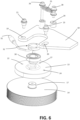
- the rotative sensor 10 comprises a stationary body 13 connected, by ways explained in the following, to the pedestal 3, and a wheel 14 rotatable with respect to the stationary body 13, which is meshed by the tubular body 11, particularly by the auxiliary crown 12 of the tubular body 11, so that a rotation of the column 2 matches a rotation of the wheel 14 of the sensor 10.
- the stationary body 13 and wheel 14 are positioned with respect to the pedestal 2 so that the wheel 14 rotation axis with respect to the stationary body 13 is offset, in other words does not overlap, with respect to the column 2 rotation axis with respect to the pedestal 3.
- the wheel 14 rotation axis with respect to the stationary body 13 is parallel to the column 2 rotation axis with respect to the pedestal 3.
- the wheel 14 comprises circumferentially placed raised elements 15, shaped as teeth developing along the axial direction of wheel 14, apt to deform the auxiliary crown 12 of tubular body 11 and therefore in order to ensure a high friction between this latter and wheel 14.
- wheel 14 can comprise a deformable circumferential crown (not shown in the figures), made of a deformable material having characteristics analogous to the ones described with reference to the possible deformable material by which the auxiliary crown 12 of tubular body 11 can be made, according to what was previously described.
- the deformable crown is removable from the wheel 14, so that can be substituted in case of wear and/or failure.
- the deformable crown can be positioned above the raised elements 15 in order to generally take a toothed shape.
- wheel 14 and tubular body 11 can have different diameters from each other so that between them there is a transmission ratio different from 1, given by the ratio of the corresponding diameters.
- wheel 14 preferably comprises a shaft 17 connected to the stationary body 13 by one or more bearings 30.
- the sensor 10 comprises means 31 for sensing the angular position of the wheel 14 of the sensor with respect to the stationary body 13. Consequently, by measuring such angular position, it is possible to obtain, knowing the beforehand cited transmission ratio, the angular position of column 2 with respect to the pedestal 3.
- the sensing means of sensor 10 comprise a magnet associated to the wheel 14 and a sensing probe associated to the stationary body 13, configured to sense the magnet angular position, and consequently the position of the wheel 14 of sensor 10, with respect to the stationary body 13 based on the magnetic field variations generated by the rotations themselves.
- the sensor 10 comprises an output 32 for transmitting a signal representative of the performed angular measurement.
- the stationary body 13 of the sensor is connected to the pedestal 3 so that it can perform oscillations, between two end positions, with respect to it, about an oscillation axis, preferably offset from the wheel 14 rotation axis with respect to the stationary body 13.
- elastic means adapted to bias the stationary body 13 towards a position, between said oscillation end positions, are provided, so that the wheel 14 is biased against the tubular body 11.
- the pedestal 3 comprises a connecting plate 18 having a first hole 19 and a crescent-shaped slot 20.
- the stationary body 13 of sensor 10 is connected to the plate 18 by a first screw 21 crossing the first hole 19 of plate 18 and fixed in a first connecting seat 22 of the stationary body 13, and by a second screw 23 crossing the crescent-shaped opening 19 of the plate 18 and fixed in a second connecting seat 24 of the stationary body 13. Consequently, the stationary body 13 of sensor 10 can oscillate with respect to the plate 18 about the first screw 21 between two end positions set by the second screw 23 sliding between the opposite ends of the crescent-shaped opening 20.
- the first seat 22 and second seat 24 are disposed in opposite positions with respect to the wheel 14 rotation axis with respect to the stationary body 13 and such that the oscillation axis of stationary body 13 with respect to the plate 18 is parallel to the wheel 14 rotation axis with respect to the stationary body 13.
- the beforehand cited elastic means comprise a coil spring 25 fixed at a first end thereof by a third screw 26 in a third seat 27 of the stationary body 13 and fixed at a second end thereof by a fourth screw 28 in a fourth seat 29 of the connecting plate 18.
- the third 27 and fourth connecting seats 29 are disposed on a side opposite with respect to the side where the wheel 14 meshes the tubular body 11.
- the coil spring 25 is tensilely preloaded.
- the preloaded coil spring 25 has a tendency, by tensilely acting, to bias the stationary body 13, and consequently the wheel 14, towards the left in Figure 4 , where the connection of this latter to the tubular body 11 is provided. Therefore, in case of oscillations/deformations of the column 2 towards the left in Figure 4 , the wheel 14 will have a tendency of following these oscillations/deformations while, in case of oscillations/deformations of the column 2 towards the right in Figure 4 , the wheel 14 will be pressed against the tubular body 11 by a greater force due to the deformation of the coil spring 25.
Landscapes
- Engineering & Computer Science (AREA)
- Mechanical Engineering (AREA)
- Automation & Control Theory (AREA)
- Jib Cranes (AREA)
- Transmission And Conversion Of Sensor Element Output (AREA)
Claims (11)
- Drehkranzkran mit begrenzter Rotation (1), umfassend: einen Sockel (3), eine Säule (2), die um eine erste Drehachse drehbar durch eine Drehkranzkopplung (6) an den Sockel (3) gekoppelt ist, Mittel zum Begrenzen der relativen Rotation der Säule (2) in Bezug auf den Sockel (3) und einen Drehsensor (10), der ausgelegt ist, einen Drehwinkel der Säule (2) in Bezug auf den Sockel (3) zu messen, wobei der Drehsensor (10) umfasst:- einen rohrförmigen Körper (11), der axial von der Basis der Säule (2) ausgeht, drehbar integral mit dieser gebildet ist und axial aus dieser zur Innenseite des Sockels (3) vorsteht;- einen stationären Körper (13), der mit dem Sockel (3) und einem Rad (14) verbunden ist, um eine zweite Drehachse in Bezug auf den stationären Körper (13) drehbar ist und in den der rohrförmige Körper (11) eingreift, wobei die zweite Drehachse des Rads (14) in Bezug auf den stationären Körper (13) versetzt ist, in Bezug auf die erste Drehachse der Säule (2) in Bezug auf den Sockel (3);- Mittel zum Erfassen der Winkelposition des Rads (14) in Bezug auf den stationären Körper (13);- eine Vielzahl von Hydraulikrohren und/oder Elektrokabeln, die durch den rohrförmigen Körper (11) führen.
- Drehkranzkran mit begrenzter Rotation (1) nach Anspruch 1, wobei der stationäre Körper (13) so mit dem Sockel (3) verbunden ist, dass er zwischen zwei Endpositionen in Bezug auf eine Oszillationsachse oszillieren kann, die in Bezug auf die zweite Drehachse des Rads (14) in Bezug auf den stationären Körper (13) versetzt ist, wobei der Drehsensor (10) ferner elastische Mittel umfasst, um den stationären Körper (13) so zu einer Position hin vorzuspannen, dass das Rad (14) gegen den rohrförmigen Körper (11) vorgespannt ist.
- Drehkranzkran mit begrenzter Rotation (1) nach Anspruch 2, wobei die Oszillationsachse des stationären Körpers (13) in Bezug auf den Sockel (3) parallel zur zweiten Drehachse des Rads (14) in Bezug auf den stationären Körper (13) ist.
- Drehkranzkran mit begrenzter Rotation (1) nach Anspruch 2 oder 3, wobei der Sockel (3) eine Verbindungsplatte (18) mit einem ersten Loch (19) und einem halbmondförmigen Schlitz (20) umfasst, wobei der stationäre Körper (13) durch eine erste Schraube (21), die das erste Loch (19) der Platte (18) durchquert und in einer ersten Verbindungsaufnahme (22) des stationären Körpers (13) fixiert ist, und durch eine zweite Schraube (23), die den halbmondförmigen Schlitz (20) der Platte (18) durchquert und in einer zweiten Verbindungsaufnahme (24) des stationären Körpers (13) fixiert ist, mit der Platte (18) verbunden ist.
- Drehkranzkran mit begrenzter Rotation (1) nach Anspruch 4, wobei die elastischen Mittel eine Spiralfeder (25) umfassen, die an einem ersten Ende davon durch eine dritte Schraube (26) in einer dritten Aufnahme (27) des stationären Körpers (13) fixiert ist und an einem zweiten Ende davon durch eine vierte Schraube (28) in einer vierten Aufnahme (29) der Verbindungsplatte (18) fixiert ist.
- Drehkranzkran mit begrenzter Rotation (1) nach einem der vorhergehenden Ansprüche, wobei die zweite Drehachse des Rads (14) in Bezug auf den stationären Körper (13) parallel zur ersten Drehachse der Säule (2) in Bezug auf den Sockel (3) ist.
- Drehkranzkran mit begrenzter Rotation (1) nach einem der vorhergehenden Ansprüche, wobei der rohrförmige Körper (11) einen zu ihm konzentrischen Hilfskranz (12) umfasst, der aus einem deformierbaren Material hergestellt ist, wobei der Hilfskranz in das Rad (14) eingreift.
- Drehkranzkran mit begrenzter Rotation (1) nach Anspruch 7, wobei das Rad (14) umlaufend angeordnete erhöhte Elemente (15) umfasst, um den Hilfskranz (12) des rohrförmigen Körpers (11) zu deformieren.
- Drehkranzkran mit begrenzter Rotation (1) nach Anspruch 7 oder 8, wobei das Rad (14) einen aus einem deformierbaren Material hergestellten umlaufenden Kranz umfasst, der mit dem Hilfskranz (12) des rohrförmigen Körpers (11) in Kontakt steht.
- Drehkranzkran mit begrenzter Rotation (1) nach mindestens einem der Ansprüche 7 und 9, wobei der Hilfskranz (12) des rohrförmigen Körpers (11) und/oder der umlaufende Kranz des Rads (14) aus einem elastomeren Material hergestellt sind.
- Drehkranzkran mit begrenzter Rotation (1) nach einem der vorhergehenden Ansprüche, wobei das Erfassungsmittel einen dem Rad (14) zugeordneten Magneten und eine dem stationären Körper (13) zugeordnete Erfassungssonde umfasst, die ausgelegt ist, die Winkelposition des Magneten in Bezug auf die Sonde zu erfassen.
Applications Claiming Priority (1)
| Application Number | Priority Date | Filing Date | Title |
|---|---|---|---|
| IT102019000015388A IT201900015388A1 (it) | 2019-09-02 | 2019-09-02 | Gru a ralla con rotazione limitata |
Publications (3)
| Publication Number | Publication Date |
|---|---|
| EP3786100A1 EP3786100A1 (de) | 2021-03-03 |
| EP3786100B1 true EP3786100B1 (de) | 2024-01-24 |
| EP3786100C0 EP3786100C0 (de) | 2024-01-24 |
Family
ID=69158215
Family Applications (1)
| Application Number | Title | Priority Date | Filing Date |
|---|---|---|---|
| EP20185576.4A Active EP3786100B1 (de) | 2019-09-02 | 2020-07-13 | Drehkranzkran mit begrenzter rotation |
Country Status (3)
| Country | Link |
|---|---|
| US (1) | US11208304B2 (de) |
| EP (1) | EP3786100B1 (de) |
| IT (1) | IT201900015388A1 (de) |
Families Citing this family (2)
| Publication number | Priority date | Publication date | Assignee | Title |
|---|---|---|---|---|
| CN115557408B (zh) * | 2022-08-25 | 2024-04-02 | 杭州大杰智能传动科技有限公司 | 一种塔机回转传动及控制系统 |
| CN117923348B (zh) * | 2024-03-25 | 2024-05-17 | 云南银塔电力建设有限公司 | 一种用于设备维修的起重平台 |
Family Cites Families (5)
| Publication number | Priority date | Publication date | Assignee | Title |
|---|---|---|---|---|
| JP2522267Y2 (ja) * | 1991-03-27 | 1997-01-08 | 極東開発工業株式会社 | ブーム装置の旋回規制装置 |
| JPH0920500A (ja) * | 1995-07-05 | 1997-01-21 | Furukawa Electric Co Ltd:The | ブーム搭載車、ブームの制御方法及び制御装置 |
| DE202010011721U1 (de) * | 2010-08-24 | 2010-10-21 | Manitowoc Crane Group France Sas | Radialspielausgleichende Drehwinkelgeberanordnung |
| JP6180962B2 (ja) * | 2014-02-26 | 2017-08-16 | 日立住友重機械建機クレーン株式会社 | 旋回式作業機械の旋回角度検出装置 |
| IT201600108686A1 (it) * | 2016-10-27 | 2018-04-27 | O Me Fa S P A Officina Mecc Fassi | Dispositivo di supporto di un cavo di un verricello di una gru |
-
2019
- 2019-09-02 IT IT102019000015388A patent/IT201900015388A1/it unknown
-
2020
- 2020-07-13 EP EP20185576.4A patent/EP3786100B1/de active Active
- 2020-08-05 US US16/985,300 patent/US11208304B2/en active Active
Also Published As
| Publication number | Publication date |
|---|---|
| US11208304B2 (en) | 2021-12-28 |
| EP3786100A1 (de) | 2021-03-03 |
| EP3786100C0 (de) | 2024-01-24 |
| IT201900015388A1 (it) | 2021-03-02 |
| US20210061625A1 (en) | 2021-03-04 |
Similar Documents
| Publication | Publication Date | Title |
|---|---|---|
| EP3786100B1 (de) | Drehkranzkran mit begrenzter rotation | |
| TWI655833B (zh) | 具電動機的減速機 | |
| US4035044A (en) | Bearing assembly | |
| US8833535B2 (en) | Constant-force device and micrometer | |
| CN108691989B (zh) | 减速装置 | |
| CN109844461B (zh) | 用于对测量对象的线性运动或旋转运动进行测量的传感器装置 | |
| JPH0351929B2 (de) | ||
| US20250012346A1 (en) | Electromechanical Cylinder | |
| CN109059735B (zh) | 一种机械设备角度检测装置 | |
| CN101166912A (zh) | 载荷感测轴承 | |
| US2943465A (en) | Adjustable spline | |
| US8572855B2 (en) | Rotary position transducer assembly which compensates for radial play | |
| CN107848119A (zh) | 用于机器人手臂的驱动布置 | |
| US20100072022A1 (en) | Torque arm assembly for a backstopping clutch | |
| AU2020387700B2 (en) | Device with stator and rotor, and wind generating set | |
| JP6146816B2 (ja) | トルク検出器 | |
| US10384916B2 (en) | Device for supporting a cable of a capstan of a crane | |
| KR102631076B1 (ko) | 베어링 장치 및 파동기어장치 | |
| EP2955396A1 (de) | Lagervorichtung mit einstellungsmitteln | |
| KR101999267B1 (ko) | 축방향력의 측정이 가능한 나사 구동장치 | |
| JP4425508B2 (ja) | 電動バルブアクチュエータにおける負荷連続検出装置 | |
| JP2016515429A (ja) | 手持ち式の動力工具 | |
| CN215338164U (zh) | 一种改进的工装结构 | |
| KR101696020B1 (ko) | 열간 압연 설비에서 동력 전달 계통의 이상 진단 장치 | |
| US11307105B1 (en) | Torque meter shaft with rotational slip enabled sensor indicating tabs |
Legal Events
| Date | Code | Title | Description |
|---|---|---|---|
| PUAI | Public reference made under article 153(3) epc to a published international application that has entered the european phase |
Free format text: ORIGINAL CODE: 0009012 |
|
| STAA | Information on the status of an ep patent application or granted ep patent |
Free format text: STATUS: THE APPLICATION HAS BEEN PUBLISHED |
|
| AK | Designated contracting states |
Kind code of ref document: A1 Designated state(s): AL AT BE BG CH CY CZ DE DK EE ES FI FR GB GR HR HU IE IS IT LI LT LU LV MC MK MT NL NO PL PT RO RS SE SI SK SM TR |
|
| AX | Request for extension of the european patent |
Extension state: BA ME |
|
| STAA | Information on the status of an ep patent application or granted ep patent |
Free format text: STATUS: REQUEST FOR EXAMINATION WAS MADE |
|
| 17P | Request for examination filed |
Effective date: 20210423 |
|
| RBV | Designated contracting states (corrected) |
Designated state(s): AL AT BE BG CH CY CZ DE DK EE ES FI FR GB GR HR HU IE IS IT LI LT LU LV MC MK MT NL NO PL PT RO RS SE SI SK SM TR |
|
| P01 | Opt-out of the competence of the unified patent court (upc) registered |
Effective date: 20230328 |
|
| GRAP | Despatch of communication of intention to grant a patent |
Free format text: ORIGINAL CODE: EPIDOSNIGR1 |
|
| STAA | Information on the status of an ep patent application or granted ep patent |
Free format text: STATUS: GRANT OF PATENT IS INTENDED |
|
| GRAS | Grant fee paid |
Free format text: ORIGINAL CODE: EPIDOSNIGR3 |
|
| GRAA | (expected) grant |
Free format text: ORIGINAL CODE: 0009210 |
|
| STAA | Information on the status of an ep patent application or granted ep patent |
Free format text: STATUS: THE PATENT HAS BEEN GRANTED |
|
| INTG | Intention to grant announced |
Effective date: 20231211 |
|
| AK | Designated contracting states |
Kind code of ref document: B1 Designated state(s): AL AT BE BG CH CY CZ DE DK EE ES FI FR GB GR HR HU IE IS IT LI LT LU LV MC MK MT NL NO PL PT RO RS SE SI SK SM TR |
|
| REG | Reference to a national code |
Ref country code: GB Ref legal event code: FG4D |
|
| REG | Reference to a national code |
Ref country code: CH Ref legal event code: EP |
|
| REG | Reference to a national code |
Ref country code: DE Ref legal event code: R096 Ref document number: 602020024717 Country of ref document: DE |
|
| REG | Reference to a national code |
Ref country code: IE Ref legal event code: FG4D |
|
| U01 | Request for unitary effect filed |
Effective date: 20240126 |
|
| P04 | Withdrawal of opt-out of the competence of the unified patent court (upc) registered |
Effective date: 20240202 |
|
| U07 | Unitary effect registered |
Designated state(s): AT BE BG DE DK EE FI FR IT LT LU LV MT NL PT SE SI Effective date: 20240207 |
|
| PG25 | Lapsed in a contracting state [announced via postgrant information from national office to epo] |
Ref country code: IS Free format text: LAPSE BECAUSE OF FAILURE TO SUBMIT A TRANSLATION OF THE DESCRIPTION OR TO PAY THE FEE WITHIN THE PRESCRIBED TIME-LIMIT Effective date: 20240524 |
|
| U20 | Renewal fee for the european patent with unitary effect paid |
Year of fee payment: 5 Effective date: 20240604 |
|
| PG25 | Lapsed in a contracting state [announced via postgrant information from national office to epo] |
Ref country code: GR Free format text: LAPSE BECAUSE OF FAILURE TO SUBMIT A TRANSLATION OF THE DESCRIPTION OR TO PAY THE FEE WITHIN THE PRESCRIBED TIME-LIMIT Effective date: 20240425 |
|
| PG25 | Lapsed in a contracting state [announced via postgrant information from national office to epo] |
Ref country code: HR Free format text: LAPSE BECAUSE OF FAILURE TO SUBMIT A TRANSLATION OF THE DESCRIPTION OR TO PAY THE FEE WITHIN THE PRESCRIBED TIME-LIMIT Effective date: 20240124 Ref country code: RS Free format text: LAPSE BECAUSE OF FAILURE TO SUBMIT A TRANSLATION OF THE DESCRIPTION OR TO PAY THE FEE WITHIN THE PRESCRIBED TIME-LIMIT Effective date: 20240424 |
|
| PG25 | Lapsed in a contracting state [announced via postgrant information from national office to epo] |
Ref country code: ES Free format text: LAPSE BECAUSE OF FAILURE TO SUBMIT A TRANSLATION OF THE DESCRIPTION OR TO PAY THE FEE WITHIN THE PRESCRIBED TIME-LIMIT Effective date: 20240124 |
|
| PG25 | Lapsed in a contracting state [announced via postgrant information from national office to epo] |
Ref country code: RS Free format text: LAPSE BECAUSE OF FAILURE TO SUBMIT A TRANSLATION OF THE DESCRIPTION OR TO PAY THE FEE WITHIN THE PRESCRIBED TIME-LIMIT Effective date: 20240424 Ref country code: NO Free format text: LAPSE BECAUSE OF FAILURE TO SUBMIT A TRANSLATION OF THE DESCRIPTION OR TO PAY THE FEE WITHIN THE PRESCRIBED TIME-LIMIT Effective date: 20240424 Ref country code: IS Free format text: LAPSE BECAUSE OF FAILURE TO SUBMIT A TRANSLATION OF THE DESCRIPTION OR TO PAY THE FEE WITHIN THE PRESCRIBED TIME-LIMIT Effective date: 20240524 Ref country code: HR Free format text: LAPSE BECAUSE OF FAILURE TO SUBMIT A TRANSLATION OF THE DESCRIPTION OR TO PAY THE FEE WITHIN THE PRESCRIBED TIME-LIMIT Effective date: 20240124 Ref country code: GR Free format text: LAPSE BECAUSE OF FAILURE TO SUBMIT A TRANSLATION OF THE DESCRIPTION OR TO PAY THE FEE WITHIN THE PRESCRIBED TIME-LIMIT Effective date: 20240425 Ref country code: ES Free format text: LAPSE BECAUSE OF FAILURE TO SUBMIT A TRANSLATION OF THE DESCRIPTION OR TO PAY THE FEE WITHIN THE PRESCRIBED TIME-LIMIT Effective date: 20240124 |
|
| PG25 | Lapsed in a contracting state [announced via postgrant information from national office to epo] |
Ref country code: PL Free format text: LAPSE BECAUSE OF FAILURE TO SUBMIT A TRANSLATION OF THE DESCRIPTION OR TO PAY THE FEE WITHIN THE PRESCRIBED TIME-LIMIT Effective date: 20240124 |
|
| PG25 | Lapsed in a contracting state [announced via postgrant information from national office to epo] |
Ref country code: PL Free format text: LAPSE BECAUSE OF FAILURE TO SUBMIT A TRANSLATION OF THE DESCRIPTION OR TO PAY THE FEE WITHIN THE PRESCRIBED TIME-LIMIT Effective date: 20240124 |
|
| PG25 | Lapsed in a contracting state [announced via postgrant information from national office to epo] |
Ref country code: SM Free format text: LAPSE BECAUSE OF FAILURE TO SUBMIT A TRANSLATION OF THE DESCRIPTION OR TO PAY THE FEE WITHIN THE PRESCRIBED TIME-LIMIT Effective date: 20240124 |
|
| PG25 | Lapsed in a contracting state [announced via postgrant information from national office to epo] |
Ref country code: CZ Free format text: LAPSE BECAUSE OF FAILURE TO SUBMIT A TRANSLATION OF THE DESCRIPTION OR TO PAY THE FEE WITHIN THE PRESCRIBED TIME-LIMIT Effective date: 20240124 |
|
| REG | Reference to a national code |
Ref country code: DE Ref legal event code: R097 Ref document number: 602020024717 Country of ref document: DE |
|
| PG25 | Lapsed in a contracting state [announced via postgrant information from national office to epo] |
Ref country code: SK Free format text: LAPSE BECAUSE OF FAILURE TO SUBMIT A TRANSLATION OF THE DESCRIPTION OR TO PAY THE FEE WITHIN THE PRESCRIBED TIME-LIMIT Effective date: 20240124 |
|
| PG25 | Lapsed in a contracting state [announced via postgrant information from national office to epo] |
Ref country code: SM Free format text: LAPSE BECAUSE OF FAILURE TO SUBMIT A TRANSLATION OF THE DESCRIPTION OR TO PAY THE FEE WITHIN THE PRESCRIBED TIME-LIMIT Effective date: 20240124 Ref country code: SK Free format text: LAPSE BECAUSE OF FAILURE TO SUBMIT A TRANSLATION OF THE DESCRIPTION OR TO PAY THE FEE WITHIN THE PRESCRIBED TIME-LIMIT Effective date: 20240124 Ref country code: CZ Free format text: LAPSE BECAUSE OF FAILURE TO SUBMIT A TRANSLATION OF THE DESCRIPTION OR TO PAY THE FEE WITHIN THE PRESCRIBED TIME-LIMIT Effective date: 20240124 |
|
| PLBE | No opposition filed within time limit |
Free format text: ORIGINAL CODE: 0009261 |
|
| STAA | Information on the status of an ep patent application or granted ep patent |
Free format text: STATUS: NO OPPOSITION FILED WITHIN TIME LIMIT |
|
| 26N | No opposition filed |
Effective date: 20241025 |
|
| P05 | Withdrawal of opt-out of the competence of the unified patent court (upc) changed |
Free format text: CASE NUMBER: APP_6108/2024 Effective date: 20240207 |
|
| PG25 | Lapsed in a contracting state [announced via postgrant information from national office to epo] |
Ref country code: MC Free format text: LAPSE BECAUSE OF FAILURE TO SUBMIT A TRANSLATION OF THE DESCRIPTION OR TO PAY THE FEE WITHIN THE PRESCRIBED TIME-LIMIT Effective date: 20240124 |
|
| REG | Reference to a national code |
Ref country code: CH Ref legal event code: PL |
|
| GBPC | Gb: european patent ceased through non-payment of renewal fee |
Effective date: 20240713 |
|
| PG25 | Lapsed in a contracting state [announced via postgrant information from national office to epo] |
Ref country code: CH Free format text: LAPSE BECAUSE OF NON-PAYMENT OF DUE FEES Effective date: 20240731 |
|
| PG25 | Lapsed in a contracting state [announced via postgrant information from national office to epo] |
Ref country code: GB Free format text: LAPSE BECAUSE OF NON-PAYMENT OF DUE FEES Effective date: 20240713 |
|
| U20 | Renewal fee for the european patent with unitary effect paid |
Year of fee payment: 6 Effective date: 20250508 |
|
| PG25 | Lapsed in a contracting state [announced via postgrant information from national office to epo] |
Ref country code: IE Free format text: LAPSE BECAUSE OF NON-PAYMENT OF DUE FEES Effective date: 20240713 |
|
| PG25 | Lapsed in a contracting state [announced via postgrant information from national office to epo] |
Ref country code: RO Free format text: LAPSE BECAUSE OF FAILURE TO SUBMIT A TRANSLATION OF THE DESCRIPTION OR TO PAY THE FEE WITHIN THE PRESCRIBED TIME-LIMIT Effective date: 20240124 |
|
| PG25 | Lapsed in a contracting state [announced via postgrant information from national office to epo] |
Ref country code: CY Free format text: LAPSE BECAUSE OF FAILURE TO SUBMIT A TRANSLATION OF THE DESCRIPTION OR TO PAY THE FEE WITHIN THE PRESCRIBED TIME-LIMIT; INVALID AB INITIO Effective date: 20200713 |
|
| PG25 | Lapsed in a contracting state [announced via postgrant information from national office to epo] |
Ref country code: HU Free format text: LAPSE BECAUSE OF FAILURE TO SUBMIT A TRANSLATION OF THE DESCRIPTION OR TO PAY THE FEE WITHIN THE PRESCRIBED TIME-LIMIT; INVALID AB INITIO Effective date: 20200713 |