EP3787190A1 - Antenne für nahfeldkommunikation - Google Patents
Antenne für nahfeldkommunikation Download PDFInfo
- Publication number
- EP3787190A1 EP3787190A1 EP19193810.9A EP19193810A EP3787190A1 EP 3787190 A1 EP3787190 A1 EP 3787190A1 EP 19193810 A EP19193810 A EP 19193810A EP 3787190 A1 EP3787190 A1 EP 3787190A1
- Authority
- EP
- European Patent Office
- Prior art keywords
- antenna
- portions
- primary
- widths
- file
- Prior art date
- Legal status (The legal status is an assumption and is not a legal conclusion. Google has not performed a legal analysis and makes no representation as to the accuracy of the status listed.)
- Pending
Links
Images


Classifications
-
- H—ELECTRICITY
- H04—ELECTRIC COMMUNICATION TECHNIQUE
- H04B—TRANSMISSION
- H04B5/00—Near-field transmission systems, e.g. inductive or capacitive transmission systems
- H04B5/20—Near-field transmission systems, e.g. inductive or capacitive transmission systems characterised by the transmission technique; characterised by the transmission medium
- H04B5/24—Inductive coupling
- H04B5/26—Inductive coupling using coils
-
- H—ELECTRICITY
- H01—ELECTRIC ELEMENTS
- H01Q—ANTENNAS, i.e. RADIO AERIALS
- H01Q1/00—Details of, or arrangements associated with, antennas
- H01Q1/44—Details of, or arrangements associated with, antennas using equipment having another main function to serve additionally as an antenna, e.g. means for giving an antenna an aesthetic aspect
-
- H—ELECTRICITY
- H01—ELECTRIC ELEMENTS
- H01Q—ANTENNAS, i.e. RADIO AERIALS
- H01Q7/00—Loop antennas with a substantially uniform current distribution around the loop and having a directional radiation pattern in a plane perpendicular to the plane of the loop
-
- H—ELECTRICITY
- H01—ELECTRIC ELEMENTS
- H01Q—ANTENNAS, i.e. RADIO AERIALS
- H01Q1/00—Details of, or arrangements associated with, antennas
- H01Q1/36—Structural form of radiating elements, e.g. cone, spiral, umbrella; Particular materials used therewith
-
- H—ELECTRICITY
- H04—ELECTRIC COMMUNICATION TECHNIQUE
- H04B—TRANSMISSION
- H04B5/00—Near-field transmission systems, e.g. inductive or capacitive transmission systems
- H04B5/70—Near-field transmission systems, e.g. inductive or capacitive transmission systems specially adapted for specific purposes
Definitions
- the technical field of the present invention relates to that of antennas, and more precisely that of near-field communication antennas.
- Antennas for near field communications are known from the state of the art. These antennas can be visible to the user, and it is possible to modify the shape of the antenna in order to improve their visual appearance.
- the present invention proposes to resolve these drawbacks totally or partially by means of an antenna for near-field communication comprising an electrically conductive track; said electrically conductive track defining a primary shape of said antenna and comprising an arrangement of primary portions of the same widths and of secondary portions of widths different from those of the primary portions so that said arrangement forms a figurative image.
- said widths of said secondary portions are discrete or vary gradually.
- said widths of said primary portions and / or said secondary portions are less than 400 ⁇ m, in particular less than 200 ⁇ m and preferably less than 150 ⁇ m.
- the antenna comprises a distance between said primary portions and said secondary portions, said distance being less than 400 ⁇ m, in particular less than 200 ⁇ m and preferably less than 150 ⁇ m.
- said electrically conductive track has a length of between 300 mm and 1200 mm, in particular between 400 mm and 1000 mm, preferably between 500 mm and 900 mm.
- the present invention is in the form of an antenna 100 for near field communication comprising an electrically conductive track 102 with a figurative image 120.
- This electrically conductive track 102 defines a primary shape 110 of the antenna, which may be in the form of a circular or rectangular spiral, a coil or the like.
- the spiral can be single or multiple and can be a regular and / or irregular curve which begins at a central point and then moves away from this central point more and more with each turn, at the same time as it turns around this point. central.
- a serpentine can be a line which changes direction in a regular and / or irregular manner.
- This primary form of antenna can be formed by the electrically conductive track 102 , the length of which can be between 300 mm and 1200 mm, in particular between 400 mm and 1000 mm, preferably between 500 mm and 900 mm.
- the track electrically conductive 102 that is to say the hairspring comprises 4 turns, in other words 4 turns, with a general diameter of 40mm
- the length can be 500mm and given that the operation can be at 13MHz, this results in a value of approximately 1.5 ⁇ H to which is added a capacitance of 100 pF.
- the electrically conductive track 102 comprises an arrangement of primary portions 121 and secondary portions 122.
- the primary portions 121 have an identical width between them, while the secondary portions 122 have different widths from each other and different from those of the primary portions 121 of so that the arrangement of the primary portions 121 and of the secondary portions 122 forms a figurative image 120. More exactly, the widths of the primary portions 121 and / or of the secondary portions 122 are less than 400 ⁇ m, in particular less than 200 ⁇ m and preferably less than 200 ⁇ m. less than 150 ⁇ m.
- the modulation of these widths of the secondary portions 122 which makes it possible to modify the aesthetic appearance of the antenna without the radiofrequency circuit used having to be adapted to these modifications or more exactly to these modulations of widths. Indeed, independently of the width of the primary portions 121 and secondary portions 122, the electrically conductive track 102 forms the path of the antenna in an uninterrupted manner and draws the primary shape 110 of the antenna. It is only this variation in the widths of the secondary portions 122 and the arrangement of primary portions 121 and secondary portions 122 which forms the figurative image 120.
- This contrast can also be conditioned by the distance between the primary portions 121 and the secondary portions 122, which may be less than 400 ⁇ m, in particular less than 200 ⁇ m and preferably less than 150 ⁇ m.
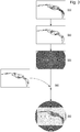
- This antenna 100 can be manufactured by a method of manufacturing an antenna 500.
- This method comprises a step of providing a first file 510 comprising a first set of data representing a figurative image 120.
- This first set of data can be represented. in a first frame of reference, that is to say in a red, green, and blue frame of reference with or without alpha channel for transparency.
- This first data set 520 is then converted into a second data set with a second frame of reference which can be a black and white image or an image whose light intensity can be modulated so as to give a gray representation.
- This second set of data can be included in a second file.
- a third file 530 representing the primary form 110 of the antenna 100 formed by an electrically conductive track 102, is provided by the user and then combined with the second file.
- This primary shape 110 may be a circular or rectangular spiral, a coil or the like.
Landscapes
- Engineering & Computer Science (AREA)
- Computer Networks & Wireless Communication (AREA)
- Signal Processing (AREA)
- Details Of Aerials (AREA)
Priority Applications (4)
| Application Number | Priority Date | Filing Date | Title |
|---|---|---|---|
| EP19193810.9A EP3787190A1 (de) | 2019-08-27 | 2019-08-27 | Antenne für nahfeldkommunikation |
| US16/927,319 US11527823B2 (en) | 2019-08-27 | 2020-07-13 | Antenna for near-field communication |
| JP2020127057A JP6982144B2 (ja) | 2019-08-27 | 2020-07-28 | 近距離無線通信用アンテナ |
| CN202010877223.1A CN112448165B (zh) | 2019-08-27 | 2020-08-27 | 用于近场通信的天线 |
Applications Claiming Priority (1)
| Application Number | Priority Date | Filing Date | Title |
|---|---|---|---|
| EP19193810.9A EP3787190A1 (de) | 2019-08-27 | 2019-08-27 | Antenne für nahfeldkommunikation |
Publications (1)
| Publication Number | Publication Date |
|---|---|
| EP3787190A1 true EP3787190A1 (de) | 2021-03-03 |
Family
ID=67777061
Family Applications (1)
| Application Number | Title | Priority Date | Filing Date |
|---|---|---|---|
| EP19193810.9A Pending EP3787190A1 (de) | 2019-08-27 | 2019-08-27 | Antenne für nahfeldkommunikation |
Country Status (4)
| Country | Link |
|---|---|
| US (1) | US11527823B2 (de) |
| EP (1) | EP3787190A1 (de) |
| JP (1) | JP6982144B2 (de) |
| CN (1) | CN112448165B (de) |
Citations (3)
| Publication number | Priority date | Publication date | Assignee | Title |
|---|---|---|---|---|
| JP2019016868A (ja) * | 2017-07-04 | 2019-01-31 | 株式会社村田製作所 | アンテナ装置、コイルアンテナ及び電子機器 |
| JP2019041273A (ja) * | 2017-08-25 | 2019-03-14 | 株式会社村田製作所 | コイルアンテナ及び電子機器 |
| US20190109373A1 (en) * | 2017-10-11 | 2019-04-11 | Samsung Electro-Mechanics Co., Ltd. | Coil assembly |
Family Cites Families (12)
| Publication number | Priority date | Publication date | Assignee | Title |
|---|---|---|---|---|
| JP3675924B2 (ja) * | 1996-01-17 | 2005-07-27 | 株式会社五藤光学研究所 | プラネタリウムにおける星雲又は星団の投映方法及びそれに使用する投映原板の作成方法 |
| JP2000331142A (ja) * | 1999-05-20 | 2000-11-30 | Toppan Printing Co Ltd | デザインアンテナを設けた非接触型icカード |
| JP2001319205A (ja) * | 2000-05-10 | 2001-11-16 | Kobayashi Kirokushi Co Ltd | Icカード |
| JP2004326380A (ja) * | 2003-04-24 | 2004-11-18 | Dainippon Printing Co Ltd | Rfidタグ |
| WO2006106759A1 (ja) * | 2005-04-01 | 2006-10-12 | Nissha Printing Co., Ltd. | 車両用透明アンテナおよびアンテナ付き車両用ガラス |
| EP1868263A4 (de) | 2005-04-01 | 2009-08-12 | Nissha Printing | Transparente antenne zur anzeige, lichtdurchlässiges glied zur anzeige mit antenne und teil zur unterbringung mit antenne |
| CN1917280A (zh) * | 2005-08-19 | 2007-02-21 | 比亚迪股份有限公司 | 一种手机天线及其制造方法 |
| KR20080061274A (ko) * | 2006-12-27 | 2008-07-02 | 가부시키가이샤 한도오따이 에네루기 켄큐쇼 | 안테나 및 그 안테나를 가지는 반도체 장치 |
| JP2017524315A (ja) * | 2014-07-01 | 2017-08-24 | エムシー10 インコーポレイテッドMc10,Inc. | コンフォーマル電子デバイス |
| DE102015102731A1 (de) | 2015-02-25 | 2016-08-25 | Ovd Kinegram Ag | Mehrschichtkörper und Sicherheitsdokument |
| JP6950321B2 (ja) * | 2017-07-20 | 2021-10-13 | 凸版印刷株式会社 | 印刷物 |
| CN107834169B (zh) * | 2017-10-17 | 2020-08-11 | 武汉理工大学 | 一种高电导率多层石墨烯厚膜及阻抗加载形射频识别电子标签 |
-
2019
- 2019-08-27 EP EP19193810.9A patent/EP3787190A1/de active Pending
-
2020
- 2020-07-13 US US16/927,319 patent/US11527823B2/en active Active
- 2020-07-28 JP JP2020127057A patent/JP6982144B2/ja active Active
- 2020-08-27 CN CN202010877223.1A patent/CN112448165B/zh active Active
Patent Citations (3)
| Publication number | Priority date | Publication date | Assignee | Title |
|---|---|---|---|---|
| JP2019016868A (ja) * | 2017-07-04 | 2019-01-31 | 株式会社村田製作所 | アンテナ装置、コイルアンテナ及び電子機器 |
| JP2019041273A (ja) * | 2017-08-25 | 2019-03-14 | 株式会社村田製作所 | コイルアンテナ及び電子機器 |
| US20190109373A1 (en) * | 2017-10-11 | 2019-04-11 | Samsung Electro-Mechanics Co., Ltd. | Coil assembly |
Also Published As
| Publication number | Publication date |
|---|---|
| CN112448165B (zh) | 2023-08-22 |
| JP2021040306A (ja) | 2021-03-11 |
| JP6982144B2 (ja) | 2021-12-17 |
| US11527823B2 (en) | 2022-12-13 |
| US20210066792A1 (en) | 2021-03-04 |
| CN112448165A (zh) | 2021-03-05 |
Similar Documents
| Publication | Publication Date | Title |
|---|---|---|
| EP0604338A1 (de) | Wenig Raum beanspruchende, breitbandige Antenne mit zugehörigem Sendeempfänger | |
| EP2688138B1 (de) | Mehrfachstrahlantenne und -antennensystem, das kompakte Quellen umfasst, und Satellitentelekommunikationssystem das mindestens eine Antenne dieser Art umfasst | |
| EP1445829A1 (de) | Subreflektor für Cassegrain-Mikrowellenantenne | |
| FR2845829A1 (fr) | Systeme d'antenne a double reflecteur a foyer en forme d'anneau multi bande | |
| EP2178152A1 (de) | Elektronische Umschaltvorrichtung für Hochfrequenzsignale | |
| EP3224897B1 (de) | Filtriervorrichtung und filtrieranordnung mit einer elektrisch leitenden streifenstruktur | |
| EP1430566B1 (de) | Breit- oder multi-bandantenne | |
| FR2718292A1 (fr) | Antenne d'émission et/ou de réception de signaux électromagnétiques, en particulier hyperfréquences, et dispositif utilisant une telle antenne. | |
| EP3352301A1 (de) | Antenne für mobile kommunikationsvorrichtung | |
| EP0285524B1 (de) | Radiale Kombiniereinrichtung für elektromagnetische Wellen | |
| FR2760132A1 (fr) | Antenne alimentee par bobines cote a cote pour un poste radio portable | |
| CA2683048C (fr) | Antenne a elements rayonnants inclines | |
| WO2022023126A1 (fr) | Dispositif a metasurface | |
| EP1540768A1 (de) | Helixförmige breitbandantenne | |
| EP1393411B1 (de) | Resonatorantenne mit rundstrahlcharakteristik | |
| FR2861222A1 (fr) | Antenne planaire bi-bande | |
| WO2022101415A1 (fr) | Antenne de communications radio constituée d'un fil métallique rigide préalablement cintré, structure de support et terminal de paiement correspondant | |
| FR3053547B1 (fr) | Carte electronique | |
| EP0762534B1 (de) | Verfahren zur Verbreiterung des Strahlungsdiagramms einer Gruppenantenne mit verteilten Elementen in einem Volumen | |
| EP0954051A1 (de) | Schlitzantenne, insbesondere für eine Uhr | |
| EP4148902A1 (de) | Elektromagnetisches system mit winkelabweichung der hauptkeule einer antenne | |
| EP1956682B1 (de) | Umschaltbare Monopolantenne | |
| WO2018189117A1 (fr) | Antenne configurée pour être conformée à une surface transparente, dispositif d'affichage et dispositif de paiement électronique correspondants | |
| EP1825566B1 (de) | Verbesserung an einer verbotenen, aktiven photonenbandantenne | |
| FR2859315A1 (fr) | Antenne planaire multibandes |
Legal Events
| Date | Code | Title | Description |
|---|---|---|---|
| PUAI | Public reference made under article 153(3) epc to a published international application that has entered the european phase |
Free format text: ORIGINAL CODE: 0009012 |
|
| STAA | Information on the status of an ep patent application or granted ep patent |
Free format text: STATUS: THE APPLICATION HAS BEEN PUBLISHED |
|
| AK | Designated contracting states |
Kind code of ref document: A1 Designated state(s): AL AT BE BG CH CY CZ DE DK EE ES FI FR GB GR HR HU IE IS IT LI LT LU LV MC MK MT NL NO PL PT RO RS SE SI SK SM TR |
|
| AX | Request for extension of the european patent |
Extension state: BA ME |
|
| STAA | Information on the status of an ep patent application or granted ep patent |
Free format text: STATUS: REQUEST FOR EXAMINATION WAS MADE |
|
| 17P | Request for examination filed |
Effective date: 20210903 |
|
| RBV | Designated contracting states (corrected) |
Designated state(s): AL AT BE BG CH CY CZ DE DK EE ES FI FR GB GR HR HU IE IS IT LI LT LU LV MC MK MT NL NO PL PT RO RS SE SI SK SM TR |
|
| STAA | Information on the status of an ep patent application or granted ep patent |
Free format text: STATUS: EXAMINATION IS IN PROGRESS |
|
| 17Q | First examination report despatched |
Effective date: 20230322 |
|
| P01 | Opt-out of the competence of the unified patent court (upc) registered |
Effective date: 20230615 |