EP3788356B1 - Verfahren zum betreiben eines sensors zum nachweis mindestens eines anteils einer messgaskomponente mit gebundenem sauerstoff in einem messgas - Google Patents
Verfahren zum betreiben eines sensors zum nachweis mindestens eines anteils einer messgaskomponente mit gebundenem sauerstoff in einem messgas Download PDFInfo
- Publication number
- EP3788356B1 EP3788356B1 EP19720540.4A EP19720540A EP3788356B1 EP 3788356 B1 EP3788356 B1 EP 3788356B1 EP 19720540 A EP19720540 A EP 19720540A EP 3788356 B1 EP3788356 B1 EP 3788356B1
- Authority
- EP
- European Patent Office
- Prior art keywords
- com
- voltage
- electrically conductive
- electrode
- conductive connection
- Prior art date
- Legal status (The legal status is an assumption and is not a legal conclusion. Google has not performed a legal analysis and makes no representation as to the accuracy of the status listed.)
- Active
Links
Images



Classifications
-
- G—PHYSICS
- G01—MEASURING; TESTING
- G01N—INVESTIGATING OR ANALYSING MATERIALS BY DETERMINING THEIR CHEMICAL OR PHYSICAL PROPERTIES
- G01N27/00—Investigating or analysing materials by the use of electric, electrochemical, or magnetic means
- G01N27/26—Investigating or analysing materials by the use of electric, electrochemical, or magnetic means by investigating electrochemical variables; by using electrolysis or electrophoresis
- G01N27/416—Systems
- G01N27/417—Systems using cells, i.e. more than one cell and probes with solid electrolytes
- G01N27/4175—Calibrating or checking the analyser
Definitions
- the prior art discloses a large number of methods and sensors for detecting at least a portion of the measurement gas component with bound oxygen in a gas mixture, in particular in an exhaust gas from an internal combustion engine, by detecting a proportion of oxygen that is caused by a reduction in the measurement gas component with the bound oxygen is generated, known, for example from the DE 10 2015 210 473 A1 , the DE 10 2014 224 943 A1 and the EP 2 056 100 A1 .
- Sensors for detecting at least a portion of the measurement gas component with bound oxygen in a gas mixture which are also referred to in abbreviated or simplified terms as NO x sensors or nitrogen oxide sensors, are for example in Reif, K., Deitsche, KH. et al., Kraftfahrtechnisches Taschenbuch, Springer Vieweg, Wiesbaden, 2014, pages 1338-1347 described.
- Nitrogen oxide sensors which are used today in automotive technology, work according to the limit current principle, analogous to oxygen sensors, such as lambda sensors.
- a nitrogen oxide sensor comprises a Nernst concentration cell, which is also called a reference cell, a modified oxygen pump cell and a further modified oxygen pump cell, the so-called NO x cell.
- the Nernst electrode is also located in the first cavity and the reference electrode, which together form the Nernst cell or reference cell, is located in a reference gas chamber.
- the NO x cell includes a NO x pump electrode and a counter electrode.
- the NO x pump electrode is located in a second cavity, which is connected to the first inner cavity and separated from it by a diffusion barrier.
- the The counter electrode is located in the reference gas space. All electrodes in the first and second cavity have a common return conductor.
- the so-called O2 cell removes the oxygen from the first cavity, which is connected to the exhaust gas via a diffusion barrier.
- the resulting pump current is then proportional to the oxygen content of the ambient air in the sample gas or exhaust gas flow.
- the nitrogen oxides are pumped out in the NO x cell.
- the nitrogen oxide NO x in the atmosphere in the second cavity is reduced or broken down by applying a constant pump voltage.
- the oxygen generated by reducing or breaking down the measurement gas component in the second cavity, which preferably originates from the reduction of the nitrogen oxide NO x is pumped out into a reference gas space.
- the applied pump voltage against the resistance of the NO x cell and the concentration of nitrogen oxide NO x or oxygen results in a pump current that is proportional to the content of nitrogen oxide NO x or oxygen and represents the NO x measurement signal.
- the resulting pump current I P2 is therefore a measure of the NO x concentration of the ambient air in the measurement gas or exhaust gas flow.
- the O2 cell may only be operated at low pump voltages, as otherwise NO x molecules would be dissociated again.
- the temperature of the sensor element is controlled by pulse width modulation (PWM) of the heater supply (voltage, current).
- PWM pulse width modulation
- the voltage of the PWM is tapped directly from the supply voltage (12V) of the sensor control unit (SCU) via a field effect transistor (FET).
- FET field effect transistor
- the SCU supply voltage of the system is applied to the heating meander of the sensor element in the sensor sample.
- the current of the NOx measurement signal is very small, such as. 4.5 ⁇ A at 1500 ppm NOx and therefore extremely sensitive to interference and coupling.
- a method according to claim 1 for operating a sensor for detecting at least a portion of a measuring gas component with bound oxygen in a measuring gas is therefore proposed, which at least largely avoids the disadvantages of known methods for operating these sensors and which provides a safe and reliable process at intervals of at least 500 ms Continuous diagnosis is possible without influencing or disrupting the NOx measured values.
- the sensor for detecting at least a portion of a measurement gas component with bound oxygen in a measurement gas, in particular in an exhaust gas of an internal combustion engine
- the sensor comprising a sensor element, the sensor element having a first pump cell, an outer pump electrode and an inner one Having pump electrode and which rests against a first cavity which is in communication with the measurement gas, a reference cell which has a Nernst electrode and a reference electrode and which rests against a reference gas space, and a second pump cell which has a pump electrode and a counter electrode and which rests on a second cavity
- an electronic control device which has at least a first separate connection for the first pump cell, a second separate connection for the second pump cell, a connection for a Nernst voltage and a common connection connected to the sensor element
- the outer pump electrode being connected to the first separate connection by means of a first electrically conductive connection
- the inner pump electrode being connected to the common connection by means of a second electrically conductive connection
- an evaluable measurement signal is generated, for example on the measurement resistor, which allows the distinction between an open and a closed circuit.
- an IP2 signal is generated on the IP2 measuring shunt by an external excitation, in particular in the case of an open circuit.
- An open IP2 line can also be detected in operating states in which the current IP2 is (almost) equal to zero, for example at 0 ppm NOx.
- the predetermined time is 0.08 ms to 2 ms and preferably 0.5 ms to 1 ms.
- the exact times depend on the capacities of the hardware and the internal capacities of the NOx cell. This allows a meaningful diagnosis result to be achieved on the state of the fourth electrically conductive connection in a relatively short time.
- the predetermined electrical voltage is lowered for the predetermined time. As a result, a current flow on the measuring resistor is increased and can be evaluated.
- the predetermined electrical voltage is lowered for the predetermined time in such a way that a voltage difference between the second separate connection and the common connection of 455 mV to 1500 mV and preferably 460 mV to 500 mV is formed. This causes a clearly measurable change in current on the measuring hunt. If the COM voltage is reduced, the current pulse on the line is invisible if the lines are intact. If there is a line break in the IP2 line, a significant change in current can be seen across the measuring shunt.
- the predetermined electrical voltage is lowered for the predetermined time in such a way that a voltage difference between the second separate connection and the common connection of 600 mV to 1500 mV and preferably 650 mV to 1300 mV is formed.
- the COM voltage can also be decreased by a more significant voltage difference. The effects on the measuring shunt are independent of the gas mixture and can be detected at any time in the event of a defective line.
- the fourth electrically conductive connection is identified as intact if the measurement signal shows no change for the predetermined time, and is identified as defective if the measurement signal shows a change for the predetermined time.
- the diagnosis of the state of the IP2 line can be implemented on the basis of a change in the current flow on the measuring shunt of the IP2 line.
- the measurement signal is a voltage drop across the measurement resistor. As a result, a signal that can be easily processed by the control unit can be obtained.
- a computer program is also proposed which is set up to carry out each step of the method according to the invention.
- the computer program is not part of the invention.
- an electronic storage medium is proposed on which a computer program for carrying out the method according to the invention is stored.
- the storage medium is also not part of the invention.
- An electronic control device which contains the electronic storage medium with the said computer program for carrying out the method according to the invention.
- the electronic control unit is not part of the claimed subject matter.
- a sensor for detecting at least a portion of a measurement gas component with bound oxygen in a measurement gas comprises a sensor element, the sensor element having a first pump cell, which has an outer pump electrode and an inner pump electrode, and which is located on a first cavity which is connected to the measurement gas, a reference cell which has a Nernst electrode and a reference electrode and which is in contact with a reference gas space, and a second pump cell which has a pump electrode and a counter electrode and which is in contact with a second cavity, wherein the sensor also has a control unit.
- the sensor is not part of the invention.
- a solid electrolyte is to be understood as meaning a body or object with electrolytic properties, that is to say with ion-conducting properties.
- it can be a ceramic solid electrolyte.
- This also includes the raw material of a solid electrolyte and therefore the formation as a so-called green compact or brown compact, which only becomes a solid electrolyte after sintering.
- the solid electrolyte can be designed as a solid electrolyte layer or from a plurality of solid electrolyte layers.
- a layer is to be understood as meaning a uniform mass over a surface area of a certain height, which is above, below or between other elements.
- an electrode is generally to be understood as an element which is able to contact the solid electrolyte in such a way that a current can be maintained through the solid electrolyte and the electrode.
- the electrode can comprise an element on which the ions can be incorporated into the solid electrolyte and / or removed from the solid electrolyte.
- the electrodes typically include a noble metal electrode, which can be applied to the solid electrolyte, for example as a metal-ceramic electrode, or can be connected to the solid electrolyte in some other way.
- Typical electrode materials are platinum cermet electrodes. However, other noble metals, such as gold or palladium, can in principle also be used.
- a heating element is to be understood as an element which serves to heat the solid electrolyte and the electrodes to at least their functional temperature and preferably to their operating temperature.
- the functional temperature is the temperature from which the solid electrolyte becomes conductive for ions and which is approximately 350 ° C. This is to be distinguished from the operating temperature, which is the temperature at which the sensor element is usually operated and which is higher than the functional temperature.
- the operating temperature can be from 700 ° C to 950 ° C, for example.
- the heating element can comprise a heating area and at least one feed line.
- a heating area is to be understood as the area of the heating element which, in the layer structure, overlaps with an electrode along a direction perpendicular to the surface of the sensor element.
- the heating area heats up more than the supply line during operation, so that these can be distinguished.
- the different heating can be implemented, for example, in that the heating area has a higher electrical resistance than the supply line.
- the heating area and / or the supply line are designed, for example, as an electrical resistance track and heat up when an electrical voltage is applied.
- the heating element can be made from a platinum cermet, for example.
- the UP2 voltage is reduced by the same difference, referenced to GND. This creates an overcapacitance of charged particles in the capacitor of the IP2 line, which has to flow away and depending on whether the IP2 cell is connected or not, the current flows accordingly.
- the sample When the sample is connected, it goes into the IP2 cell, when the line is not connected into the measuring device, where the current can be measured as a voltage drop across the shunt by the control unit.
- the invention is good and easy to detect by monitoring the electrical signals on the COM line. If a specific voltage change / current change on the line between the sensor and the control device is measured with an oscilloscope during normal measuring operation, the circuits and methods described in this invention are used.
- Figure 1 shows a basic structure of a sensor 100 which is particularly suitable for carrying out the method according to the invention.
- the sensor 100 which is set up to detect at least a portion of a measurement gas component with bound oxygen, hereinafter referred to as nitrogen oxide NOx by way of example, in a gas mixture, for example an exhaust gas from an internal combustion engine, includes a sensor element 110, a first pump cell 112, which is between a outer pump electrode 114 and an inner pump electrode 116 is formed.
- the outer pump electrode 114 which is separated from the surroundings of the sensor 100 by means of a porous aluminum oxide layer 118, has a first electrically conductive connection 120 via which a first pump current I P1 can be generated in the first pump cell 112.
- the first electrically conductive connection 120 is connected to a first connection P1 of an external electronic control device 122.
- the inner pump electrode 116 also has a second electrically conductive connection 124, which leads to a common connection COM of the external electronic control device 122.
- the first pump cell 112 rests against a first cavity 126, which is located in the interior of the sensor element 110 and is in communication with the measurement gas.
- a first proportion of oxygen ions which are formed from molecular oxygen from the gas mixture, can be transported between the first cavity 126 and the surroundings of the sensor 100.
- Two diffusion barriers 128 are present in the entry path from the environment to the first cavity 126.
- the sensor element 110 furthermore has an electrical reference cell 130 which has a Nernst electrode 132 and a reference electrode 134.
- the reference electrode 134 has a separate third electrically conductive connection 136 to a connection Vs of the external electronic control unit 122 for the Nernst voltage Vs. on.
- the reference cell 130 is in contact with a reference gas space 138.
- a second proportion of the oxygen ions from the first cavity 126 and / or from the environment of the sensor 100 is transported into the reference gas chamber 138 by applying a reference pump current between the connection Vs and the common connection COM.
- the value for the reference pump current is set in such a way that a defined proportion of the oxygen ions is formed in the reference gas space 138.
- the value for the first pump current I P1 is preferably also set in such a way that a fixed ratio results between the first proportion of the oxygen ions in the first cavity 126 and the second proportion of the oxygen ions in the reference gas chamber 138.
- the measuring gas component nitrogen oxide NO x with the bound oxygen also contained in the gas mixture reaches a second pump cell 140 of the sensor element 110, in particular by diffusion, largely unaffected, which can also be referred to as the “NO x pump cell”.
- the second pump cell 140 has a NO x pump electrode 142 and a NO x counter electrode 144 and rests against a second cavity 145 in the interior of the sensor element 110.
- the second cavity 145 is separated from the first cavity 126 by one of the diffusion barriers 128.
- At least one of the two electrodes NO x pump electrode 142 and / or NO x counter electrode 144 are designed such that when a voltage is applied, further molecular oxygen can be generated from the measurement gas component NO x by means of catalysis, which is formed in the second pump cell 140.
- the NO x pump electrode 142 is connected to the common terminal COM via an electrically conductive connection. Even if this is not shown in more detail, this electrically conductive connection is connected to the second electrically conductive connection 124 or is part of the same.
- the NO x counter electrode 144 has a fourth electrically conductive connection 146 via which a second pump current I P2 can be applied to the second pump cell 140.
- the fourth electrically conductive connection 146 is for this purpose with a second connection P2 of the external electronic control device 122 is connected.
- the sensor element 110 also has a heating element 148, which is connected by means of two leads 150 to connections HTR + and HTR- of the control unit 122, via which a heating current can be introduced into the heating element 148, which by generating a heating power, the sensor element 110 to the desired Can bring temperature.
- FIG. 2 shows part of the sensor 100 with part of a control device 122 connected to it.
- the control device 122 has an analog-digital converter 152 which is connected to the connection Vs for the Nernst voltage.
- the control unit 122 also has a COM voltage source 154 which is connected to the common connection COM.
- the control unit 122 also has an excitation signal source 156 which is connected to the positive pole of an operational amplifier 158.
- the operational amplifier 158 is a voltage follower.
- the COM voltage source 154 is also connected to the positive pole of the operational amplifier 158.
- the operational amplifier 158 is in turn connected to the second connection P2.
- a measuring resistor 160 is arranged in the fourth electrical line 146 between the second connection P2 and the counter electrode 144.
- Figure 3 shows the second pump cell 144 and part of the control unit 122 as an electrical circuit diagram.
- Figure 3 serves to explain the technical relationships on which the present invention is based.
- the second pump cell 140 is shown as a parallel and series connection of capacitors and resistors.
- the second electrically conductive connection 124 can be seen, which leads from the second pump cell 140 or the pump electrode 142 to the common connection COM.
- the fourth electrically conductive connection 146 can be recognized, which leads from the second pump cell 140 or the NO x counter-electrode 144 to the measuring resistor 160.
- the operational amplifier 158 is also in Figure 3 which in turn is connected to the COM voltage source 154.
- the common connection COM has a potential difference of, for example, 2.25 V with respect to the ground GND of the control unit 122.
- a predetermined electrical voltage U COM is present at the common connection COM. By changing the predetermined electrical voltage U COM , for example lowering, a voltage difference U P2 between the second separate terminal P2 and the common terminal COM is changed or lowered by the same difference, referenced to ground GND. This creates an overcapacitance of charge carriers in the capacitor 162, which has to flow away.
- the current flows away accordingly.
- the current flows into the second pump cell 140, as indicated by a first arrow 164.
- the current flows into the measuring device of the control unit 122, where the current can be measured as a voltage drop across the measuring resistor 160 by the control unit 122, as indicated by a second arrow 166.
- FIG. 11 shows a first example of a time profile of electrical voltages and measurement signals in the case of the sensor 100 with the fourth electrically conductive connection 146 intact.
- the time is plotted on the X axis 168.
- the electrical heating voltage U HTR applied to the heating element 148, the predetermined electrical voltage U COM applied to the common connection COM and the voltage drop U IP2 across the measuring resistor 160 are plotted on the Y axis 170.
- Curve 172 represents the temporal course of the predetermined electrical voltage U COM
- curve 174 represents the measurement signal 174 in the form of the temporal course of the voltage drop U IP2 across the measuring resistor 160
- curve 176 represents the temporal course of the electrical heating voltage U HTR
- the voltage excitation includes a change in the predetermined electrical voltage U COM for a predetermined time.
- the predetermined time is 0.08 ms to 1 ms, and preferably 0.5 ms to 1 ms.
- the predetermined time is 1 ms.
- the predetermined electrical voltage U COM is reduced for the predetermined time at time 178 such that a voltage difference U P2 between the second separate terminal P2 and the common terminal COM of 450 mV to 2500 mV and preferably 450 mV to 1500 mV is formed.
- a voltage difference U P2 of 465 mV is formed.
- the point in time 178 of the lowering of the predetermined electrical voltage U COM can be at a point in time at which an electrical heating voltage U HTR is applied to the heating element 148 or the electrical heating voltage U HTR is increased and the heating element 148 is thus heated.
- the fourth electrically conductive connection 146 is identified as being intact if the measurement signal 174 shows no change for the predetermined time. If there is no interruption of the fourth electrically conductive connection 146, the lowering of the predetermined electrical voltage U COM in the hardware of the control device 122 and the resulting current flow can flow away via the sensor element 110 if the fourth electrically conductive connection 146 is intact. The voltage change and the resulting current flow via the fourth electrically conductive connection 146 can no longer be measured via the measuring resistor 160. In the example shown, there is a closed circuit, so that the measurement signal 174 is unchanged for the predetermined time from the point in time 178.
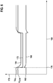
- FIG. 3 shows a second example of a time profile of electrical voltages and measurement signals in the case of the sensor 100 with a defective fourth electrically conductive connection 146. Only the differences from that in FIG Figure 4 The example shown is explained and the same components or features are provided with the same reference numerals.
- the fourth electrically conductive connection 146 is identified as defective if the measurement signal 174 has a change for the predetermined time. If there is an interruption in the fourth electrically conductive connection 146, the change in voltage at COM causes a significant flow of current on the fourth electrically conductive connection 146 via the measuring resistor 160.
- the example shown is an open circuit, so that the measurement signal 174 from the point in time 178 has a clear drop 180 for the predetermined time.
- FIG. 3 shows a third example of a time profile of electrical voltages and measurement signals in the case of the sensor 100 with the fourth electrically conductive connection 146 intact.
- the time is plotted on the X axis 168.
- the electrical voltage U P2 applied to the second pump cell 140, the predetermined electrical voltage U COM applied to the common terminal COM and a difference 182 between the electrical voltage applied to the second pump cell 140 Voltage U P2 and the predetermined electrical voltage U COM are plotted.
- Curve 172 represents the time profile of the predetermined electrical voltage U COM
- curve 184 shows the time profile of the electrical voltage U P2 applied to second pump cell 140
- curve 186 represents measurement signal 174 in the form of the time profile of the difference 182 between the electrical voltage U P2 applied to the second pump cell 140 and the predetermined electrical voltage U COM
- the control unit 122 changes the predetermined electrical voltage U COM for a predetermined time to generate a measurement signal.
- the predetermined time is 0.08 ms to 1 ms, and preferably 0.5 ms to 1 ms.
- the predetermined time is 1 ms.
- the predetermined electrical voltage U COM is lowered for the predetermined time at time 178 such that a voltage difference U P2 between the second separate terminal P2 and the common terminal COM of 450 mV to 2500 mV and preferably 460 mV to 1500 mV is formed.
- a voltage difference U P2 of 750 mV is formed.
- a sufficiently large one must open between the pump electrode 142 and the counter electrode 144 a fixed value regulated voltage U P2 is present.
- This voltage U P2 at the second pump cell 140 can be, for example, 450 mV against COM.
- the fourth electrically conductive connection 146 is identified as intact if the measurement signal 174 shows no change for the predetermined time, ie the difference 182 is 450 mV.
- the current can flow through the sensor element 110 via the sensor element 110, the charge reversal processes caused by the hardware circuit of the control unit 122 to lower the predetermined electrical voltage U COM, and the voltage change can be caused by the operational amplifier 158 set voltage within a very short time of, for example, 10 to 15 ⁇ S, depending on the aging of the second pump cell 140 or manufacturing tolerances, follow the desired 450 mV.
- the operational amplifier 158 set voltage within a very short time of, for example, 10 to 15 ⁇ S, depending on the aging of the second pump cell 140 or manufacturing tolerances, follow the desired 450 mV.
- there is a closed circuit and thus an intact fourth electrically conductive connection 146 so that the measurement signal 174 from the time 178 with an insignificant delay of 15 to 20 ⁇ S after lowering the predetermined electrical voltage U COM unchanged for the predetermined Time is.
- FIG. 4 shows a fourth example of a time profile of electrical voltages and measurement signals in the case of the sensor 100 with a defective fourth electrically conductive connection 146. Only the differences from that in FIG Figure 6 The example shown is explained and the same components or features are provided with the same reference numerals.
- the fourth electrically conductive connection 146 is identified as defective if the measurement signal 168 exhibits a change for the predetermined time. If there is an interruption in the fourth electrically conductive connection 146, the change in voltage at COM causes a significant flow of current on the fourth electrically conductive connection 146 via the measuring resistor 160.
- the measurement signal 174 from time 178 has a significantly higher potential of, for example, 750 mV instead of 450 mV in the normal case for the predetermined time. It is explicitly emphasized that for the assessment of the state of the fourth electrically conductive connection an observation of the time profile of the electrical voltage U P2 applied to the second pump cell 140 is sufficient without the difference 182 having to be considered.
Landscapes
- Chemical & Material Sciences (AREA)
- Life Sciences & Earth Sciences (AREA)
- Health & Medical Sciences (AREA)
- Biochemistry (AREA)
- Chemical Kinetics & Catalysis (AREA)
- Electrochemistry (AREA)
- Physics & Mathematics (AREA)
- Analytical Chemistry (AREA)
- Molecular Biology (AREA)
- General Health & Medical Sciences (AREA)
- General Physics & Mathematics (AREA)
- Immunology (AREA)
- Pathology (AREA)
- Investigating Or Analyzing Materials By The Use Of Electric Means (AREA)
- Measuring Oxygen Concentration In Cells (AREA)
- Combined Controls Of Internal Combustion Engines (AREA)
Description
- Aus dem Stand der Technik ist eine Vielzahl von Verfahren und Sensoren zum Nachweis mindestens eines Anteils der Messgaskomponente mit gebundenem Sauerstoff in einem Gasgemisch, insbesondere in einem Abgas einer Verbrennungskraftmaschine, durch Erfassen eines Anteils an Sauerstoff, der durch eine Reduktion der Messgaskomponente mit dem gebundenem Sauerstoff erzeugt wird, bekannt, beispielsweise aus der
DE 10 2015 210 473 A1 , derDE 10 2014 224 943 A1 und derEP 2 056 100 A1 . - Sensoren zum Nachweis mindestens eines Anteils der Messgaskomponente mit gebundenem Sauerstoff in einem Gasgemisch, die auch verkürzt oder vereinfacht NOx-Sensoren oder Stickoxid-Sensoren bezeichnet werden, sind beispielsweise in Reif, K., Deitsche, K-H. et al., Kraftfahrtechnisches Taschenbuch, Springer Vieweg, Wiesbaden, 2014, Seite 1338-1347 beschrieben.
- Stickoxid-Sensoren (= NOx-Sensoren), die heutzutage in der Automobiltechnik eingesetzt werden, funktionieren nach dem Grenzstromprinzip, analog zu Sauerstoff-Sensoren, wie beispielsweise Lambda Sensoren. Ein solcher Stickoxid-Sensor umfasst eine Nernst-Konzentrationszelle, die auch Referenzzelle genannt wird, ein modifizierte Sauerstoffpumpzelle und eine weitere modifizierte Sauerstoffpumpzelle, die sogenannte NOx-Zelle. Eine dem Abgas ausgesetzte äußere Pumpelektrode und eine innere Pumpelektrode in einem ersten Hohlraum, der vom Abgas durch eine Diffusionsbarriere getrennt ist, bilden die Sauerstoffpumpzelle. Im ersten Hohlraum befindet sich auch die Nernstelektrode und in einem Referenzgasraum die Referenzelektrode, die zusammen die Nernstzelle bzw. Referenzzelle bilden. Die NOx-Zelle umfasst eine NOx-Pumpelektrode und eine Gegenelektrode. Die NOx-Pumpelektrode befindet sich in einem zweiten Hohlraum, der mit dem ersten inneren Hohlraum verbunden und von diesem durch eine Diffusionsbarriere getrennt ist. Die Gegenelektrode befindet sich in dem Referenzgasraum. Alle Elektroden in dem ersten und zweiten Hohlraum haben einen gemeinsamen Rückleiter.
- Bei Betrieb des Stickoxid-Sensor wird der sogenannten O2-Zelle der Sauerstoff aus dem ersten Hohlraum, der über eine Diffusionsbarriere mit dem Abgas verbunden ist, entfernt. Der dadurch resultierende Pumpstrom ist dann proportional zum Sauerstoffgehalt der Umgebungsluft im Messgas- bzw. Abgasstrom. In der NOx-Zelle werden die Stickoxide abgepumpt. Das Stickoxid NOx, in der in den zweiten Hohlraum befindlichen Atmosphäre, wird durch Anlegen einer konstanten Pumpspannung reduziert bzw. abgebaut. Der durch Reduktion oder Abbau der Messgaskomponente in dem zweiten Hohlraum erzeugte Sauerstoff, der vorzugsweise aus der Reduktion des Stickoxids NOx stammt, wird in einen Referenzgasraum abgepumpt. So hat die angelegte Pumpspannung gegen den Widerstand der NOx-Zelle und der Konzentration des Stickoxids NOx bzw. Sauerstoffs einen Pumpstrom zur Folge, der proportional zum Gehalt an Stickoxid NOx bzw. Sauerstoff ist und das NOx-Messsignal darstellt.
- Der dabei resultierende Pumpstrom IP2 ist somit ein Maß für die NOx-Konzentration der Umgebungsluft im Messgas- bzw. Abgasstrom. Bei dieser Anordnung ist es wichtig, dass an der Sauerstoffzelle nicht auch die Stickoxide abgepumpt werden, da sonst an der NOx-Zelle kein Signal mehr gemessen werden könnte. Dies wird durch eine Gold-Dotierung der O2-Zelle erreicht. Zusätzlich darf die O2-Zelle nur bei niedrigen Pumpspannungen betrieben werden, da sonst wieder NOx-Moleküle dissoziiert würden.
- Trotz der Vorteile der aus dem Stand der Technik bekannten Sensoren und Verfahren zum Betreiben derselben, beinhalten diese noch Verbesserungspotenzial. Die Temperatur des Sensorelements wird durch eine Pulsweitenmodulation (PWM) der Heizerversorgung (Spannung, Strom) gesteuert. Die Spannung des PWMs wird über einen Feldeffekttransistor (FET) direkt von der Versorgungspannung (12V) der Sensorsteuereinheit (SCU) abgegriffen. Dadurch liegt in der An-Phase des PWMs die SCU-Versorgungsspannung des Systems an den Heizmäander des Sensorelements in der Sensor-Probe an. Der Strom an NOx-Messsignal ist sehr klein wie beispielsweise. 4,5 µA bei 1500 ppm NOx und damit auch äußerst empfindlich gegenüber Störungen und Einkopplungen. Aufgrund der baulichen Nähe der Heizmäander zu der NOx Zelle wird während der An-Phase des PWM-Signals durch kapazitive Kopplung und Leckströme ein Strom auf die IP2 Leitung/Zelle eingeprägt. Durch diese Störung wird ein Offset zu dem tatsächlichen NOx Wert messbar. Die Anforderungen der Umweltbehörden verlangen eine kontinuierliche und verlässliche Diagnose von Leitungsunterbrechungen der IP2 Leitung.
- Es wird daher ein Verfahren gemäß Anspruch 1 zum Betreiben eines Sensors zum Nachweis mindestens eines Anteils einer Messgaskomponente mit gebundenem Sauerstoff in einem Messgas vorgeschlagen, welches die Nachteile bekannter Verfahren zum Betreiben dieser Sensoren zumindest weitgehend vermeidet und das in Intervallen von mindestens 500 ms eine sichere und kontinuierliche Diagnose erlaubt, ohne die NOx-Messwerte zu beeinflussen bzw. zu stören.
- Bei einem erfindungsgemäßen Verfahren zum Betreiben eines Sensors zum Nachweis mindestens eines Anteils einer Messgaskomponente mit gebundenem Sauerstoff in einem Messgas, insbesondere in einem Abgas einer Verbrennungskraftmaschine, wobei der Sensor ein Sensorelement umfasst, wobei das Sensorelement eine erste Pumpzelle, die eine äußere Pumpelektrode und eine innere Pumpelektrode aufweist und die an einem ersten Hohlraum anliegt, welcher mit dem Messgas in Verbindung steht, eine Referenzzelle, welche eine Nernst-Elektrode und eine Referenzelektrode aufweist und die an einem Referenzgasraum anliegt, und eine zweite Pumpzelle, die eine Pumpelektrode und eine Gegenelektrode aufweist und die an einem zweiten Hohlraum anliegt, wird ein elektronisches Steuergerät, das zumindest über einen ersten gesonderten Anschluss für die erste Pumpzelle, einen zweiten gesonderten Anschluss für die zweite Pumpzelle, einen Anschluss für eine Nernstspannung und über einen gemeinsamen Anschluss verfügt, mit dem Sensorelement verbunden, wobei die äußere Pumpelektrode mittels einer ersten mittels einer ersten elektrisch leitenden Verbindung mit dem ersten gesonderten Anschluss verbunden wird, wobei die innere Pumpelektrode mittels einer zweiten elektrisch leitenden Verbindung mit dem gemeinsamen Anschluss verbunden wird, wobei die Referenzelektrode mittels einer dritten elektrisch leitenden Verbindung mit dem Anschluss für eine Nernstspannung verbunden wird, wobei die Pumpelektrode mittels der zweiten elektrisch leitenden Verbindung mit dem gemeinsamen Anschluss verbunden wird, wobei die Gegenelektrode mittels einer vierten elektrisch leitenden Verbindung mit dem zweiten gesonderten Anschluss verbunden wird, wobei in der vierten elektrisch leitenden Verbindung ein Messwiderstand vorgesehen wird, wobei an dem gemeinsamen Anschluss eine vorbestimmte elektrische Spannung anliegt, wobei mittels des Steuergeräts eine Veränderung der vorbestimmten elektrischen Spannung für eine vorbestimmte Zeit zum Erzeugen eines Messsignals durchgeführt wird.
- Durch die Spannungsanregung der gemeinsamen Bezugsgröße aller Zellen des Sensorelements wird ein auswertbares Messsignal erzeugt, beispielsweise an dem Messwiderstand, das die Unterscheidung zwischen einem offenen oder geschlossenen Stromkreis erlaubt. Mit anderen Worten, durch die Änderung der gemeinsamen Bezugsgröße, wird an dem IP2-Messshunt ein IP2-Signal durch eine äußere Anregung, insbesondere bei einem offenen Stromkreis, erzeugt. Damit lässt sich ein offener Stromkreis an der IP2-Leitung der NOx-Zelle auch während des Messbetriebs sicher erkennen. Auch in Betriebszuständen, in denen der Strom IP2 (nahezu) gleich null ist, wie beispielsweise bei 0 ppm NOx, kann eine offene IP2-Leitung detektiert werden.
- Bei einer Weiterbildung ist die vorbestimmte Zeit 0,08 ms bis 2 ms und bevorzugt 0,5 ms bis 1 ms. Die exakten Zeiten sind von den Kapazitäten der Hardware und den inneren Kapazitäten der NOx-Zelle abhängig. Dies erlaubt in einer relativ kurzen Zeit ein aussagekräftiges Diagnoseergebnis zum Zustand der vierten elektrisch leitenden Verbindung zu erzielen.
- Bei einer Weiterbildung wird die vorbestimmte elektrische Spannung für die vorbestimmte Zeit abgesenkt. Dadurch wird ein Stromfluss an dem Messwiderstand erhöht und kann ausgewertet werden.
- Bei einer Weiterbildung wird die vorbestimmte elektrische Spannung für die vorbestimmte Zeit derart abgesenkt, dass eine Spannungsdifferenz zwischen dem zweiten gesonderten Anschluss und dem gemeinsamen Anschluss von 455 mV bis 1500mV und bevorzugt 460 mV bis 500 mV gebildet wird. Dadurch wird an dem Messhunt eine deutlich messbare Stromänderung verursacht. Wird die COM-Spannung abgesenkt, so ist der Strompuls auf der Leitung, bei intakten Leitungen, unsichtbar. Liegt eine Leitungsunterbrechung der IP2-Leitung vor, so ist eine signifikante Stromänderung über dem Messshunt erkennbar. Durch die Absenkung der COM-Spannung, bei offener Leitung, wird die Spannungsdifferenz zwischen UP2 und COM-Spannung erhöht (abweichend von den nominellen 450 mV), wodurch an dem NOx Messshunt ein Spannungsabfall der einem Strom entspricht messbar ist. Wird die Absenkung bei intakter Leitung durchgeführt, werden die Ströme aus den umlade Prozessen der Hardware in die NOx Zelle geleitet und sind für den Messshunt kaum sichtbar. Dies bedeutet, dass eine Unterscheidung zwischen einer offenen Leitung und einem 0 ppm NOx-Gehalt sicher detektierbar ist.
- Bei einer Weiterbildung wird die vorbestimmte elektrische Spannung für die vorbestimmte Zeit derart abgesenkt, dass eine Spannungsdifferenz zwischen dem zweiten gesonderten Anschluss und dem gemeinsamen Anschluss von 600 mV bis 1500 mV und bevorzugt 650 mV bis 1300 mV gebildet wird. Als Alternative zur geringfügigen Absenkung kann die COM-Spannung auch um eine signifikantere Spannungsdifferenz abgesenkt werden. Die Auswirkungen auf den Messshunt sind Gasgemisch unabhängig und können jeder Zeit bei einer defekten Leitung detektiert werden.
- Erfindungsgemäß wird die vierte elektrisch leitende Verbindung als intakt identifiziert, falls das Messsignal für die vorbestimmte Zeit keine Veränderung aufweist, und wird als defekt identifiziert, falls das Messsignal für die vorbestimmte Zeit eine Veränderung aufweist. Beispielsweise lässt sich die Diagnose zum Zustand der IP2-Leitung anhand einer Veränderung des Stromflusses an dem Messshunt der IP2-Leitung realisieren.
- Durch kurzzeitiges Absenken der Spannungen am virtuellen Ground (COM), der NOx-Zelle (IP2), O2-Zelle und auch Vs, wird an dem IP2-Messshunt eine deutlich messbare Stromänderung, bei nicht intakter IP2 Leitung, verursacht, nicht aber an den Leitungen Vs und IP1. Wird die COM-Spannung nur für eine geringe Zeit abgesenkt, so ist der Strompuls auf der Leitung, bei intakten Leitungen, kaum sichtbar, da sich die Differenz der beiden Leitungen (IP2 zu COM) kaum unterscheidet und der Strom aus den Umladeprozessen der Hardwareschaltung in die NOx-Zelle fließt und nicht über den Messshunt. Liegt ein "Open Wire"-Fehler vor, so ist eine deutliche Stromänderung über dem Messshunt erkennbar.
- In einer von zwei erfindungsgemäßen Alternativen ist das Messsignal ein Spannungsabfall über den Messwiderstand. Dadurch kann ein gut von dem Steuergerät verarbeitbares Signal gewonnen werden.
- Es wird zudem ein Computerprogramm vorgeschlagen, welches eingerichtet ist, jeden Schritt des erfindungsgemäßen Verfahrens durchzuführen. Das Computerprogramm ist nicht Teil der Erfindung.
- Weiterhin wird ein elektronisches Speichermedium vorgeschlagen, auf welchem ein Computerprogramm zur Durchführung des erfindungsgemäßen Verfahrens gespeichert ist. Das Speichermedium ist auch nicht Teil der Erfindung.
- Ein elektronisches Steuergerät ist auch vorgesehen, welches das elektronische Speichermedium mit dem besagten Computerprogramm zur Durchführung des erfindungsgemäßen Verfahrens enthält. Das elektronische Steuergerät ist nicht Teil des beanspruchten Gegenstands.
- Schließlich umfasst ein Sensor zum Nachweis mindestens eines Anteils einer Messgaskomponente mit gebundenem Sauerstoff in einem Messgas, insbesondere in einem Abgas einer Verbrennungskraftmaschine, ein Sensorelement, wobei das Sensorelement eine erste Pumpzelle, die einer äußere Pumpelektrode und eine innere Pumpelektrode aufweist und die an einem ersten Hohlraum anliegt, welcher mit dem Messgas in Verbindung steht, eine Referenzzelle, welcher eine Nernst-Elektrode und eine Referenzelektrode aufweist und die an einem Referenzgasraum anliegt, und eine zweite Pumpzelle, die eine Pumpelektrode und eine Gegenelektrode aufweist und die an einem zweiten Hohlraum anliegt, wobei der Sensor weiterhin ein Steuergerät aufweist. Der Sensor ist nicht Teil der Erfindung.
- Unter einem Festelektrolyten ist im Rahmen der vorliegenden Erfindung ein Körper oder Gegenstand mit elektrolytischen Eigenschaften, also mit Ionen leitenden Eigenschaften, zu verstehen. Insbesondere kann es sich um einen keramischen Festelektrolyten handeln. Dies umfasst auch das Rohmaterial eines Festelektrolyten und daher die Ausbildung als so genannter Grünling oder Braunling, der erst nach einem Sintern zu einem Festelektrolyten wird. Insbesondere kann der Festelektrolyt als Festelektrolytschicht oder aus mehreren Festelektrolytschichten ausgebildet sei. Unter einer Schicht ist im Rahmen der vorliegenden Erfindung eine einheitliche Masse in flächenhafter Ausdehnung einer gewissen Höhe zu verstehen, die über, unter oder zwischen anderen Elementen liegt.
- Unter einer Elektrode ist im Rahmen der vorliegenden Erfindung allgemein ein Element zu verstehen, welches in der Lage ist, den Festelektrolyten derart zu kontaktieren, dass durch den Festelektrolyten und die Elektrode ein Strom aufrechterhalten werden kann. Dementsprechend kann die Elektrode ein Element umfassen, an welchem die Ionen in den Festelektrolyten eingebaut und/oder aus dem Festelektrolyten ausgebaut werden können. Typischerweise umfassen die Elektroden eine Edelmetallelektrode, welche beispielsweise als Metall-Keramik-Elektrode auf dem Festelektrolyten aufgebracht sein kann oder auf andere Weise mit dem Festelektrolyten in Verbindung stehen kann. Typische Elektrodenmaterialien sind Platin-Cermet-Elektroden. Auch andere Edelmetalle, wie beispielsweise Gold oder Palladium, sind jedoch grundsätzlich einsetzbar.
- Unter einem Heizelement ist im Rahmen der vorliegenden Erfindung ein Element zu verstehen, das zum Erwärmen des Festelektrolyten und der Elektroden auf mindestens ihre Funktionstemperatur und vorzugsweise auf ihre Betriebstemperatur dient. Die Funktionstemperatur ist diejenige Temperatur, ab der der Festelektrolyt für Ionen leitend wird und die ungefähr 350 °C beträgt. Davon ist die Betriebstemperatur zu unterscheiden, die diejenige Temperatur ist, bei der das Sensorelement üblicherweise betrieben wird und die höher ist als die Funktionstemperatur. Die Betriebstemperatur kann beispielsweise von 700 °C bis 950 °C sein. Das Heizelement kann einen Heizbereich und mindestens eine Zuleitungsbahn umfassen. Unter einem Heizbereich ist im Rahmen der vorliegenden Erfindung der Bereich des Heizelements zu verstehen, der in dem Schichtaufbau entlang einer zu der Oberfläche des Sensorelements senkrechten Richtung mit einer Elektrode überlappt. Üblicherweise erwärmt sich der Heizbereich während des Betriebs stärker als die Zuleitungsbahn, so dass diese unterscheidbar sind. Die unterschiedliche Erwärmung kann beispielsweise dadurch realisiert werden, dass der Heizbereich einen höheren elektrischen Widerstand aufweist als die Zuleitungsbahn. Der Heizbereich und/oder die Zuleitung sind beispielsweise als elektrische Widerstandsbahn ausgebildet und erwärmen sich durch Anlegen einer elektrischen Spannung. Das Heizelement kann beispielsweise aus einem Platin-Cermet hergestellt sein.
- Durch das Absenken der COM Spannung wird die UP2 Spannung um die gleiche Differenz, referenziert zu GND, abgesenkt. Dadurch entstehen im Kondensator der IP2-Leitung eine Ladungsteilchenüberkapazität, die abfließen muss und je nach dem ob die IP2 Zelle verbunden ist oder nicht, fließt der Strom entsprechend ab. Bei verbunden Probe in die IP2-Zell rein, bei nicht verbundener Leitung in die Messvorrichtung hinein, wo der Strom als Spannungsabfall über den Shunt vom Steuergerät gemessen werden kann.
- Die Erfindung ist gut und einfach durch die Überwachung der elektrischen Signale auf der COM-Leitung nachweisbar. Werden während des normalen Messbetriebs spezielle ein Spannungsänderung/Stromänderung auf der Leitung zwischen Sensor und Steuergerät mit einem Oszilloskop gemessen, so werden die in dieser Erfindung beschriebenen Schaltungen und Verfahren verwendet.
- Weitere optionale Einzelheiten und Merkmale der Erfindung ergeben sich aus der nachfolgenden Beschreibung bevorzugter Ausführungsbeispiele, welche in den Figuren schematisch dargestellt sind.
- Es zeigen:
-
Figur 1 einen prinzipiellen Aufbau eines Sensors, -
Figur 2 einen Teil des Sensors mit einem Teil eines daran angeschlossenen Steuergeräts, -
Figur 3 die zweite Pumpzelle und einen Teil des Steuergeräts als elektrisches Schaltbild, -
Figur 4 ein erstes Beispiel für einen zeitlichen Verlauf von elektrischen Spannungen und Messsignal bei dem Sensor bei intakter vierter elektrisch leitender Verbindung, -
Figur 5 ein zweites Beispiel für einen zeitlichen Verlauf von elektrischen Spannungen und Messsignal bei dem Sensor bei defekter vierter elektrisch leitender Verbindung und -
Figur 6 ein drittes Beispiel für einen zeitlichen Verlauf von elektrischen Spannungen, elektrischen Strömen und Messsignal bei dem Sensor mit intakter vierter elektrischer Leitung. -
Figur 7 ein viertes Beispiel für einen zeitlichen Verlauf von elektrischen Spannungen (NOx-Pumpspannung), elektrischen Strömen und Messsignal bei dem Sensor mit defekter vierter elektrischer Leitung. -
Figur 1 zeigt einen prinzipiellen Aufbau eines Sensors 100, welcher zur Durchführung des erfindungsgemäßen Verfahrens besonders geeignet ist. - Der Sensor 100, welcher zum Nachweis mindestens eines Anteils einer Messgaskomponente mit gebundenem Sauerstoff, im Folgenden beispielhaft als Stickoxid NOx bezeichnet, in einem Gasgemisch, beispielhaft einem Abgas einer Verbrennungskraftmaschine, eingerichtet ist, umfasst hierzu ein Sensorelement 110 eine erste Pumpzelle 112, welche zwischen einer äußeren Pumpelektrode 114 und einer inneren Pumpelektrode 116 ausgebildet ist. Die äußere Pumpelektrode 114, welche mittels einer porösen Aluminiumoxidschicht 118 von der Umgebung des Sensors 100 getrennt ist, verfügt hierbei über eine erste elektrisch leitende Verbindung 120, über welche sich ein erster Pumpstrom IP1 in der ersten Pumpzelle 112 erzeugen lässt. Die erste elektrisch leitende Verbindung 120 ist hierzu mit einem ersten Anschluss P1 eines externen elektronischen Steuergeräts 122 verbunden. Um einen vollständigen Stromkreis zu erhalten, verfügt die innere Pumpelektrode 116 ebenfalls über eine zweite elektrisch leitende Verbindung 124, welche zu einem gemeinsamen Anschluss COM des externen elektronischen Steuergeräts 122 führt. Die erste Pumpzelle 112 liegt an einem ersten Hohlraum 126 an, der sich im Inneren des Sensorelements 110 befindet und mit dem Messgas in Verbindung steht. Durch Erzeugen des ersten Pumpstroms IP1 in der ersten Pumpzelle 112 lässt sich ein erster Anteil von Sauerstoffionen, welche aus molekularem Sauerstoff aus dem Gasgemisch gebildet werden, zwischen dem ersten Hohlraum 126 und der Umgebung des Sensors 100 transportieren. In dem Eintrittsweg aus der Umgebung zu dem ersten Hohlraum 126 sind zwei Diffusionsbarrieren 128 vorhanden.
- Das Sensorelement 110 weist weiterhin eine elektrische Referenzzelle 130 auf, welche eine Nernst-Elektrode 132 und eine Referenzelektrode 134 aufweist.
- Während die Nernst-Elektrode 132 über die zweite elektrisch leitende Verbindung 124 zusammen mit der inneren Pumpelektrode 116 zu dem gemeinsamen Anschluss COM verfügt, weist die Referenzelektrode 134 eine gesonderte dritte elektrisch leitende Verbindung 136 zu einem Anschluss Vs des externen elektronischen Steuergeräts 122 für die Nernstspannung Vs auf. Die Referenzzelle 130 liegt an einem Referenzgasraum 138 an. Ein zweiter Anteil der Sauerstoffionen aus dem ersten Hohlraum 126 und/oder aus der Umgebung des Sensors 100 wird in den Referenzgasraum 138 durch Anlegen eines Referenz-Pumpstroms zwischen dem Anschluss Vs und dem gemeinsamen Anschluss COM transportiert. Hierbei wird der Wert für den Referenz-Pumpstrom derart eingestellt, dass sich ein festgelegter Anteil der Sauerstoffionen in dem Referenzgasraum 138 ausbildet. Vorzugsweise wird in diesem Zusammenhang auch der Wert für den ersten Pumpstrom IP1 derart eingestellt, dass sich ein festgelegtes Verhältnis zwischen dem ersten Anteil der Sauerstoffionen in dem ersten Hohlraum 126 und dem zweiten Anteil der Sauerstoffionen in dem Referenzgasraum 138 ergibt.
- Die in dem Gasgemisch weiterhin enthaltene Messgaskomponente Stickoxid NOx mit dem gebundenen Sauerstoff gelangt, insbesondere durch Diffusion, weitgehend unbeeinflusst in eine zweite Pumpzelle 140 des Sensorelements 110, welche auch als "NOx-Pumpzelle" bezeichnet werden kann. Die zweite Pumpzelle 140 weist eine NOx-Pumpelektrode 142 und eine NOx-Gegenelektrode 144 auf und liegt an einem zweiten Hohlraum 145 im Inneren des Sensorelements 110 an. Der zweite Hohlraum 145 ist von dem ersten Hohlraum 126 durch eine der Diffusionsbarrieren 128 getrennt. Wenigstens eine der beiden Elektroden NOx-Pumpelektrode 142 und/oder NOx-Gegenelektrode 144 sind derart ausgestaltet, dass bei Anlegen einer Spannung mittels Katalyse aus der Messgaskomponente NOx weiterer molekularer Sauerstoff erzeugt werden kann, welcher in der zweiten Pumpzelle 140 gebildet wird.
- Die NOx-Pumpelektrode 142 ist über eine elektrisch leitende Verbindung mit dem gemeinsamen Anschluss COM verbunden. Auch wenn dies nicht näher dargestellt ist, ist diese elektrisch leitende Verbindung mit der zweiten elektrisch leitenden Verbindung 124 verbunden bzw. Teil derselben. Die NOx-Gegenelektrode 144 weist eine vierte elektrisch leitende Verbindung 146 auf, über welche ein zweiter Pumpstrom IP2 an die zweite Pumpzelle 140 angelegt werden kann. Die vierte elektrisch leitende Verbindung 146 ist hierzu mit einem zweiten Anschluss P2 des externen elektronischen Steuergeräts 122 verbunden. Bei Anlegen eines zweiten Pumpstroms IP2 an die zweite Pumpzelle 140 wird ein Anteil von weiteren Sauerstoffionen, welche aus dem weiteren molekularen Sauerstoff gebildet wurden, in den Referenzgasraum 138 transportiert.
- Das Sensorelement 110 verfügt weiterhin über ein Heizelement 148, welches mittels zweier Zuleitungen 150 mit Anschlüssen HTR+ und HTR- des Steuergeräts 122 verbunden ist, über welche ein Heizstrom in das Heizelement 148 eingebracht werden kann, welches mittels Erzeugen einer Heizleistung das Sensorelement 110 auf die gewünschte Temperatur bringen kann.
-
Figur 2 zeigt einen Teil des Sensors 100 mit einem Teil eines daran angeschlossenen Steuergeräts 122. Das Steuergerät 122 weist einen Analog-Digital-Wandler 152 auf, der mit dem Anschluss Vs für die Nernstspannung verbunden ist. Das Steuergerät 122 weist weiterhin eine COM-Spannungsquelle 154 auf, die mit dem gemeinsamen Anschluss COM verbunden ist. Das Steuergerät 122 weist weiterhin eine Anregungssignalquelle 156 auf, die mit dem Pluspol eines Operationsverstärkers 158 verbunden ist. Bei dem gezeigten Ausführungsbeispiel ist der Operationsverstärker 158 ein Spannungsfolger. Die COM-Spannungsquelle 154 ist ebenfalls mit dem Pluspol des Operationsverstärkers 158 verbunden. Der Operationsverstärker 158 ist wiederum mit dem zweiten Anschluss P2 verbunden. In der vierten elektrischen Leitung 146 ist zwischen dem zweiten Anschluss P2 und der Gegenelektrode 144 ein Messwiderstand 160 angeordnet. -
Figur 3 zeigt die zweite Pumpzelle 144 und einen Teil des Steuergeräts 122 als elektrisches Schaltbild.Figur 3 dient dabei zur Erklärung der technischen Zusammenhänge, auf denen die vorliegende Erfindung beruht. Vereinfacht ist die zweite Pumpzelle 140 als Parallel- und Reihenschaltung von Kondensatoren und Widerständen dargestellt. InFigur 3 ist die zweite elektrisch leitende Verbindung 124 zu erkennen, die von der zweiten Pumpzelle 140 bzw. der Pumpelektrode 142 zu dem gemeinsamen Anschluss COM führt. Weiterhin ist inFigur 3 die vierte elektrisch leitende Verbindung 146 zu erkennen, die von der zweiten Pumpzelle 140 bzw. der NOx-Gegenelektrode 144 zu dem Messwiderstand 160 führt. Der Operationsverstärker 158 ist ebenfalls inFigur 3 dargestellt, der wiederum mit der COM-Spannungsquelle 154 verbunden ist. In der vierten elektrisch leitenden Verbindung 146 ist zwischen dem Messwiderstand 160 und der zweiten Pumpzelle 140 ein Kondensator 162 angeordnet, der wiederum mit der Masse GND des Steuergeräts 122 verbunden ist. Der gemeinsame Anschluss COM hat gegenüber der Masse GND des Steuergeräts 122 einen Potentialunterschied von beispielsweise 2,25 V. An dem gemeinsamen Anschluss COM liegt eine vorbestimmte elektrische Spannung UCOM an. Durch Verändern der vorbestimmten elektrischen Spannung UCOM, wie beispielsweise Absenken, wird eine Spannungsdifferenz UP2 zwischen dem zweiten gesonderten Anschluss P2 und dem gemeinsamen Anschluss COM um die gleiche Differenz, referenziert zur Masse GND, verändert bzw. abgesenkt. Dadurch entsteht im Kondensator 162 eine Ladungsträgerüberkapazität, die abfließen muss. Je nach dem ob die zweite Pumpzelle 140 verbunden ist oder nicht, d.h. die vierte elektrisch leitende Verbindung 146 intakt oder defekt ist, fließt der Strom entsprechend ab. Bei verbundener zweiter Pumpzelle 140 bzw. intakter vierter elektrisch leitender Verbindung 146 fließt der Strom in die zweite Pumpzelle 140 hinein, wie durch einen ersten Pfeil 164 angedeutet ist. Bei nicht verbundener zweiter Pumpzelle 140 bzw. defekter vierter elektrisch leitender Verbindung 146 fließt der Strom in die Messvorrichtung des Steuergeräts 122 hinein, wo der Strom als Spannungsabfall über den Messwiderstand 160 vom Steuergerät 122 gemessen werden kann, wie durch einen zweiten Pfeil 166 angedeutet ist. -
Figur 4 zeigt ein erstes Beispiel für einen zeitlichen Verlauf von elektrischen Spannungen und Messsignal bei dem Sensor 100 bei intakter vierter elektrisch leitender Verbindung 146. Auf der X-Achse 168 ist die Zeit aufgetragen. Auf der Y-Achse 170 sind die an das Heizelement 148 angelegte elektrische Heizspannung UHTR, die an dem gemeinsamen Anschluss COM anliegende vorbestimmte elektrische Spannung UCOM und der Spannungsabfall UIP2 über den Messwiderstand 160 aufgetragen. Die Kurve 172 stellt den zeitlichen der Verlauf der vorbestimmten elektrischen Spannung UCOM dar, die Kurve 174 stellt das Messsignal 174 in Form des zeitlichen Verlaufs des Spannungsabfalls UIP2 über den Messwiderstand 160 dar und die Kurve 176 stellt den zeitlichen Verlauf der elektrischen Heizspannung UHTR dar. Zur Durchführung einer Diagnose der vierten elektrischen Leitung 146, die den zweiten gesonderten Anschluss P2 mit der Pumpzelle 140 bzw. der Gegenelektrode 144 verbindet, wird mittels des Steuergeräts 122 eine Veränderung der vorbestimmten elektrischen Spannung UCOM zum Erzeugen eines Messsignals an dem Messwiderstand 160 durchgeführt. Die Spannungsanregung umfasst eine Veränderung der vorbestimmten elektrischen Spannung UCOM für eine vorbestimmte Zeit. Die vorbestimmte Zeit ist 0,08 ms bis 1 ms und bevorzugt 0,5 ms bis 1 ms. Diese Zeiten sind in Abhängigkeit von der verwendeten Hardwareschaltung und können sich je nach Änderung der Kapazitäten und Impedanzen im Sensorelement 110 und in der Messhardware unterscheiden, bzw. die hier angegebenen Zeiten über- oder unterschreiten. Bei dem gezeigten Beispiel ist die vorbestimmte Zeit 1 ms. Bei dem gezeigten Beispiel wird zum Zeitpunkt 178 die vorbestimmte elektrische Spannung UCOM für die vorbestimmte Zeit derart abgesenkt wird, dass eine Spannungsdifferenz UP2 zwischen dem zweiten gesonderten Anschluss P2 und dem gemeinsamen Anschluss COM von 450 mV bis 2500 mV und bevorzugt 450 mV bis 1500 mV gebildet wird. Beispielsweise wird eine Spannungsdifferenz UP2 von 465 mV gebildet. Der Zeitpunkt 178 der Absenkung der vorbestimmten elektrische Spannung UCOM kann zu einem Zeitpunkt liegen, bei dem an das Heizelement 148 eine elektrische Heizspannung UHTR angelegt wird bzw. die elektrische Heizspannung UHTR erhöht wird und das Heizelement 148 somit heizt. Die vierte elektrisch leitende Verbindung 146 wird als intakt identifiziert, falls das Messsignal 174 für die vorbestimmte Zeit keine Veränderung aufweist. Liegt keine Unterbrechung der vierten elektrisch leitenden Verbindung 146 vor, so kann durch die Umladeprozesse der Absenkung der vorbestimmten elektrischen Spannung UCOM in der Hardware des Steuergeräts 122 und der daraus resultierenden Stromfluss bei intakter vierter elektrisch leitender Verbindung 146 über das Sensorelement 110 abfließen. Die Spannungsänderung und der daraus resultierenden Stromfluss über die vierte elektrisch leitende Verbindung 146 kann nicht mehr über den Messwiderstand 160 gemessen werden. Bei dem gezeigten Beispiel, liegt ein geschlossener Stromkreis vor, so dass das Messsignal 174 ab dem Zeitpunkt 178 unverändert für die vorbestimmte Zeit ist. -
Figur 5 zeigt ein zweites Beispiel für einen zeitlichen Verlauf von elektrischen Spannungen und Messsignal bei dem Sensor 100 bei defekter vierter elektrisch leitender Verbindung 146. Nachstehend werden lediglich die Unterschiede zu dem inFigur 4 gezeigten Beispiel erläutert und gleiche Bauteile bzw. Merkmale sind mit gleichen Bezugszeichen versehen. Die vierte elektrisch leitende Verbindung 146 wird als defekt identifiziert, falls das Messsignal 174 für die vorbestimmte Zeit eine Veränderung aufweist. Liegt eine Unterbrechung der vierten elektrisch leitenden Verbindung 146 vor, so wird durch die Spannungsänderung an COM ein deutlicher Stromfluss auf der vierten elektrisch leitenden Verbindung 146 über dem Messwiderstand 160 verursacht. Bei dem gezeigten Beispiel, liegt ein offener Stromkreis vor, so dass das Messsignal 174 ab dem Zeitpunkt 178 einen deutlichen Abfall 180 für die vorbestimmte Zeit aufweist. -
Figur 6 zeigt ein drittes Beispiel für einen zeitlichen Verlauf von elektrischen Spannungen und Messsignal bei dem Sensor 100 bei intakter vierter elektrisch leitender Verbindung 146. Auf der X-Achse 168 ist die Zeit aufgetragen. Auf der Y-Achse 170 sind von oben nach unten gesehen die an die zweite Pumpzelle 140 angelegte elektrische Spannung UP2, die an dem gemeinsamen Anschluss COM anliegende vorbestimmte elektrische Spannung UCOM und eine Differenz 182 zwischen der die an die zweite Pumpzelle 140 angelegten elektrischen Spannung UP2 und der vorbestimmten elektrischen Spannung UCOM aufgetragen. Die Kurve 172 stellt den zeitlichen der Verlauf der vorbestimmten elektrischen Spannung UCOM dar, die Kurve 184 stellt den zeitlichen Verlauf der an die zweite Pumpzelle 140 angelegten elektrischen Spannung UP2 dar und die Kurve 186 stellt das Messsignal 174 in Form des zeitlichen Verlaufs der Differenz 182 zwischen der die an die zweite Pumpzelle 140 angelegten elektrischen Spannung UP2 und der vorbestimmten elektrischen Spannung UCOM dar. Zur Durchführung einer Diagnose der vierten elektrischen Leitung 146, die den zweiten gesonderten Anschluss P2 mit der Pumpzelle 140 bzw. der Gegenelektrode 144 verbindet, wird mittels des Steuergeräts 122 Veränderung der vorbestimmten elektrischen Spannung UCOM für eine vorbestimmte Zeit zum Erzeugen eines Messsignals durchgeführt. Die vorbestimmte Zeit ist 0,08 ms bis 1 ms und bevorzugt 0,5 ms bis 1 ms. Diese Zeiten sind in Abhängigkeit von der Verwendeten Hardwareschaltung und können sich je nach Änderung der Kapazitäten und Impedanzen im Sensorelement 110 und in der Messhardware des Steuergeräts 122 unterscheiden, bzw. die hier angegebenen Zeiten über- oder unterschreiten. Bei dem gezeigten Beispiel ist die vorbestimmte Zeit 1 ms. Bei dem gezeigten Beispiel wird zum Zeitpunkt 178 die vorbestimmte elektrische Spannung UCOM für die vorbestimmte Zeit derart abgesenkt wird, dass eine Spannungsdifferenz UP2 zwischen dem zweiten gesonderten Anschluss P2 und dem gemeinsamen Anschluss COM von 450 mV bis 2500 mV und bevorzugt 460 mV bis 1500 mV gebildet wird. Beispielsweise wird eine Spannungsdifferenz UP2 von 750 mV gebildet. - Um die zweite Pumpzelle 140 treiben zu können, muss zwischen der Pumpelektrode 142 und der Gegenelektrode 144 eine ausreichend große, auf einen festen Wert geregelte Spannung UP2 anliegen. Diese Spannung UP2 an der zweiten Pumpzelle 140 kann zum Beispiel 450 mV gegen COM sein. Die vierte elektrisch leitende Verbindung 146 wird als intakt identifiziert, falls das Messsignal 174 für die vorbestimmte Zeit keine Veränderung aufweist, d.h. die Differenz 182 bei 450 mV liegt. Liegt keine Unterbrechung der vierten elektrisch leitenden Verbindung 146 vor, so kann über das Sensorelement 110, die durch die Hardwareschaltung des Steuergeräts 122 verursachten Umladeprozesse der Absenkung der vorbestimmten elektrischen Spannung UCOM der Strom durch das Sensorelement 110 abfließen und die Spannungsänderung kann der durch die Operationsverstärker 158 gestellten Spannung innerhalb kürzester Zeit von beispielsweise 10 bis 15 µS je nach Alterung der zweiten Pumpzelle 140 bzw. Fertigungstoleranzen auf die angestrebten 450 mV folgen. Bei dem gezeigten Beispiel, liegt ein geschlossener Stromkreis und somit eine intakte vierte elektrisch leitende Verbindung 146 vor, so dass das Messsignal 174 ab dem Zeitpunkt 178 mit einer unwesentlichen Verzögerung von 15 bis 20 µS nach Absenkung der vorbestimmten elektrischen Spannung UCOM unverändert für die vorbestimmte Zeit ist.
-
Figur 7 zeigt ein viertes Beispiel für einen zeitlichen Verlauf von elektrischen Spannungen und Messsignal bei dem Sensor 100 bei defekter vierter elektrisch leitender Verbindung 146. Nachstehend werden lediglich die Unterschiede zu dem inFigur 6 gezeigten Beispiel erläutert und gleiche Bauteile bzw. Merkmale sind mit gleichen Bezugszeichen versehen. Die vierte elektrisch leitende Verbindung 146 wird als defekt identifiziert, falls das Messsignal 168 für die vorbestimmte Zeit eine Veränderung aufweist. Liegt eine Unterbrechung der vierten elektrisch leitenden Verbindung 146 vor, so wird durch die Spannungsänderung an COM ein deutlicher Stromfluss auf der vierten elektrisch leitenden Verbindung 146 über dem Messwiderstand 160 verursacht. Bei dem gezeigten Beispiel, liegt ein offener Stromkreis vor, so dass das Messsignal 174 ab dem Zeitpunkt 178 ein deutlich höheres Potential von beispielsweise 750 mV anstatt 450 mV im Normalfall für die vorbestimmte Zeit aufweist. Es wird explizit betont, dass für die Beurteilung des Zustands der vierten elektrisch leitenden Verbindung eine Beobachtung des zeitlichen Verlaufs der an die zweite Pumpzelle 140 angelegten elektrischen Spannung UP2 alleine ausreicht, ohne dass die Differenz 182 betrachtet werden muss.
Claims (5)
- Verfahren zum Betreiben eines Sensors (100) zum Nachweis mindestens eines Anteils einer Messgaskomponente mit gebundenem Sauerstoff in einem Messgas, insbesondere in einem Abgas einer Verbrennungskraftmaschine, umfassend ein Sensorelement (110), wobei das Sensorelement (110) eine erste Pumpzelle (112), die eine äußere Pumpelektrode (114) und eine innere Pumpelektrode (116) aufweist und die an einem ersten Hohlraum (126) anliegt, welcher mit dem Messgas in Verbindung steht, eine Referenzzelle (130), welche eine Nernst-Elektrode (132) und eine Referenzelektrode (134) aufweist und die an einem Referenzgasraum (138) anliegt, und eine zweite Pumpzelle (140), die eine Pumpelektrode (142) und eine Gegenelektrode (144) aufweist und die an einem zweiten Hohlraum (145) anliegt, wobei ein elektronisches Steuergerät (122), das zumindest über einen ersten gesonderten Anschluss (P1) für die erste Pumpzelle (112), einen zweiten gesonderten Anschluss (P2) für die zweite Pumpzelle (140), einen Anschluss für eine Nernstspannung (Vs) und über einen gemeinsamen Anschluss (COM) verfügt, mit dem Sensorelement (110) verbunden wird, wobei die äußere Pumpelektrode (114) mittels einer ersten mittels einer ersten elektrisch leitenden Verbindung (120) mit dem ersten gesonderten Anschluss (P1) verbunden wird, wobei die innere Pumpelektrode (116) mittels einer zweiten elektrisch leitenden Verbindung (124) mit dem gemeinsamen Anschluss (COM) verbunden wird, wobei die Referenzelektrode (134) mittels einer dritten elektrisch leitenden Verbindung (136) mit dem Anschluss für eine Nernstspannung (Vs) verbunden wird, wobei die Pumpelektrode (142) mittels der zweiten elektrisch leitenden Verbindung (124) mit dem gemeinsamen Anschluss (COM) verbunden wird, wobei die Gegenelektrode (144) mittels einer vierten elektrisch leitenden Verbindung (146) mit dem zweiten gesonderten Anschluss (P2) verbunden wird, wobei in der vierten elektrisch leitenden Verbindung (146) ein Messwiderstand (160) vorgesehen wird, wobei an dem gemeinsamen Anschluss (COM) eine vorbestimmte elektrische Spannung (UCOM) anliegt, wobei die vierte elektrisch leitende Verbindung (146) zwischen dem Messwiderstand (160) und der zweiten Pumpzelle (140) mit einem Kondensator (162) verbunden ist, der weiterhin mit einer Masse (GND) des Steuergeräts (122) verbunden ist, wobei mittels des Steuergeräts (122) eine Veränderung der vorbestimmten elektrischen Spannung (UCOM) für eine vorbestimmte Zeit zum Erzeugen eines Messsignals (168) durchgeführt wird, wobei das Messsignal (168) gegeben ist durch den zeitlichen Verlauf eines Spannungsabfalls (UIP2) über dem Messwiderstand (160) oder durch den zeitlichen Verlauf einer Differenz (182) zwischen einer an die zweite Pumpzelle (140) angelegten elektrischen Spannung (UP2) und der vorbestimmten elektrischen Spannung (UCOM), wobei die vierte elektrisch leitende Verbindung (146) als intakt identifiziert wird, falls das Messsignal (168) für die vorbestimmte Zeit keine Veränderung aufweist, und als defekt identifiziert wird, falls das Messsignal (168) für die vorbestimmte Zeit eine Veränderung aufweist.
- Verfahren nach Anspruch 1, wobei die vorbestimmte Zeit 0,08 ms bis 1 ms und bevorzugt 0,5 ms bis 1 ms ist.
- Verfahren nach Anspruch 1 oder 2, wobei die vorbestimmte elektrische Spannung (UCOM) für die vorbestimmte Zeit abgesenkt wird.
- Verfahren nach Anspruch 3, wobei die vorbestimmte elektrische Spannung (UCOM) für die vorbestimmte Zeit derart abgesenkt wird, dass eine Spannungsdifferenz (UP2) zwischen dem zweiten gesonderten Anschluss (P2) und dem gemeinsamen Anschluss (COM) von 450 mV bis 1,2 V gebildet wird.
- Verfahren nach Anspruch 3, wobei die vorbestimmte elektrische Spannung (UCOM) für die vorbestimmte Zeit derart abgesenkt wird, dass eine Spannungsdifferenz (UP2) zwischen dem zweiten gesonderten Anschluss (P2) und dem gemeinsamen Anschluss (COM) von 450 mV bis 1500 mV und bevorzugt 600 mV bis 1300 mV gebildet wird.
Applications Claiming Priority (2)
| Application Number | Priority Date | Filing Date | Title |
|---|---|---|---|
| DE102018206765.1A DE102018206765A1 (de) | 2018-05-02 | 2018-05-02 | Verfahren zum Betreiben eines Sensors zum Nachweis mindestens eines Anteils einer Messgaskomponente mit gebundenem Sauerstoff in einem Messgas |
| PCT/EP2019/060712 WO2019211182A1 (de) | 2018-05-02 | 2019-04-26 | Verfahren zum betreiben eines sensors zum nachweis mindestens eines anteils einer messgaskomponente mit gebundenem sauerstoff in einem messgas |
Publications (2)
| Publication Number | Publication Date |
|---|---|
| EP3788356A1 EP3788356A1 (de) | 2021-03-10 |
| EP3788356B1 true EP3788356B1 (de) | 2021-12-22 |
Family
ID=66334455
Family Applications (1)
| Application Number | Title | Priority Date | Filing Date |
|---|---|---|---|
| EP19720540.4A Active EP3788356B1 (de) | 2018-05-02 | 2019-04-26 | Verfahren zum betreiben eines sensors zum nachweis mindestens eines anteils einer messgaskomponente mit gebundenem sauerstoff in einem messgas |
Country Status (5)
| Country | Link |
|---|---|
| EP (1) | EP3788356B1 (de) |
| CN (1) | CN112384795B (de) |
| DE (1) | DE102018206765A1 (de) |
| ES (1) | ES2908886T3 (de) |
| WO (1) | WO2019211182A1 (de) |
Families Citing this family (1)
| Publication number | Priority date | Publication date | Assignee | Title |
|---|---|---|---|---|
| DE102022210329A1 (de) * | 2022-09-29 | 2024-04-04 | Robert Bosch Gesellschaft mit beschränkter Haftung | Verfahren zum Betreiben eines Sensors zum Nachweis mindestens eines Anteils einer Messgaskomponente mit gebundenem Sauerstoff in einem Messgas |
Family Cites Families (8)
| Publication number | Priority date | Publication date | Assignee | Title |
|---|---|---|---|---|
| DE10049685A1 (de) * | 2000-10-07 | 2002-04-11 | Volkswagen Ag | Verfahren und Vorrichtung zur Eigendiagnose eines NOX-Sensors |
| DE102004016986B3 (de) * | 2004-04-02 | 2005-10-06 | Siemens Ag | Vorrichtung und Verfahren zur Messung mehrerer Abgasbestandteile |
| DE102006061954A1 (de) * | 2006-12-29 | 2008-07-03 | Robert Bosch Gmbh | Sensorelement mit zusätzlicher Fettgasregelung |
| US9518954B2 (en) * | 2007-11-05 | 2016-12-13 | Ngk Spark Plug Co., Ltd. | Gas sensor control device |
| DE102007062800A1 (de) * | 2007-12-27 | 2009-07-02 | Robert Bosch Gmbh | Verfahren zur Bestimmung einer Gaszusammensetzung in einem Messgasraum |
| DE102015210473A1 (de) * | 2014-09-11 | 2016-03-17 | Robert Bosch Gmbh | Verfahren und Vorrichtung zum Nachweis mindestens eines Anteils der Messgaskomponente mit gebundenem Sauerstoff in einem Gasgemisch |
| DE102014224943A1 (de) * | 2014-12-04 | 2016-06-09 | Robert Bosch Gmbh | Verfahren zur Erkennung von mindestens zwei Arten von elektrischen Fehlern in mindestens einem Stromkreis |
| EP3064937B1 (de) * | 2015-03-06 | 2021-02-24 | Elster GmbH | Betriebsverfahren für eine Breitbandlambdasonde |
-
2018
- 2018-05-02 DE DE102018206765.1A patent/DE102018206765A1/de active Pending
-
2019
- 2019-04-26 EP EP19720540.4A patent/EP3788356B1/de active Active
- 2019-04-26 ES ES19720540T patent/ES2908886T3/es active Active
- 2019-04-26 CN CN201980044669.1A patent/CN112384795B/zh active Active
- 2019-04-26 WO PCT/EP2019/060712 patent/WO2019211182A1/de not_active Ceased
Also Published As
| Publication number | Publication date |
|---|---|
| EP3788356A1 (de) | 2021-03-10 |
| CN112384795B (zh) | 2023-11-21 |
| WO2019211182A1 (de) | 2019-11-07 |
| DE102018206765A1 (de) | 2019-11-07 |
| CN112384795A (zh) | 2021-02-19 |
| ES2908886T3 (es) | 2022-05-04 |
Similar Documents
| Publication | Publication Date | Title |
|---|---|---|
| DE69821410T2 (de) | Gassensor | |
| DE10339684B4 (de) | Gassensor-Störungsermittlungsvorrichtung zur Erfassung des Vorliegens oder Nichtvorliegens eines Störzustands eines Gassensors mit einer Vielzahl von Zellen | |
| DE69734140T2 (de) | Gas Sensor | |
| EP1616174B1 (de) | Verfahren zum betreiben eines gassensors | |
| EP3596453B1 (de) | Sensor und verfahren zum betreiben eines sensors zur erfassung mindestens einer eigenschaft eines messgases in einem messgasraum | |
| DE10392160T5 (de) | NOx-Konzentrationsmessvorrichtung und Vorrichtung zur Selbstdiagnose eines NOx-Sensors sowie Selbstdiagnoseverfahren dafür | |
| WO2016165997A1 (de) | Verfahren zum betreiben eines sensors zur erfassung mindestens einer eigenschaft eines messgases in einem messgasraum | |
| EP3788356B1 (de) | Verfahren zum betreiben eines sensors zum nachweis mindestens eines anteils einer messgaskomponente mit gebundenem sauerstoff in einem messgas | |
| WO2019170639A1 (de) | Verfahren zum betreiben eines sensors zum nachweis mindestens eines anteils einer messgaskomponente mit gebundenem sauerstoff in einem messgas | |
| WO2024068533A1 (de) | Diagnose-verfahren zum betreiben eines sensors zum nachweis mindestens eines anteils einer messgaskomponente mit gebundenem sauerstoff in einem messgas | |
| DE102018203313A1 (de) | Verfahren zum Betreiben eines Sensors zum Nachweis mindestens eines Anteils einer Messgaskomponente mit gebundenem Sauerstoff in einem Messgas | |
| DE19803532A1 (de) | Elektrochemischer Meßfühler | |
| EP3818366B1 (de) | Verfahren zum betreiben eines sensors zum nachweis mindestens eines anteils einer messgaskomponente mit gebundenem sauerstoff in einem messgas | |
| EP3622281B1 (de) | Verfahren zur bestimmung der temperatur eines festelektrolyt-gassensors | |
| DE102012224374A1 (de) | Verfahren zur Diagnose einer elektrischen Leitung zu einer Elektrode eines Sensorelements zur Erfassung mindestens einer Eigenschaft eines Messgases in einem Messgasraum | |
| DE102016215881A1 (de) | Verfahren zur Durchführung eines Erholungsprozesses von Gassensoren | |
| DE102011003514A1 (de) | Verfahren und Überwachungsgerät zur Überwachung zumindest einer Funktion eines chemosensitiven Feldeffekttransistors | |
| EP3818367B1 (de) | Verfahren zum betreiben eines sensors zum nachweis mindestens eines anteils einer messgaskomponente mit gebundenem sauerstoff in einem messgas | |
| EP3899520B1 (de) | Verfahren zur verringerung von messfehlern bei der erfassung von ammoniak beim betreiben eines sensorsystems | |
| DE102015201396A1 (de) | Sensor zur Erfassung mindestens einer Eigenschaft eines Messgases in einem Messgasraum | |
| EP4139670B1 (de) | Verfahren zur bestimmung einer sauerstoffkonzentration in einem abgas | |
| DE102013216227A1 (de) | Kapazitive Eigendiagnose des Elektrodensystems eines Partikelsensors | |
| WO2019120789A1 (de) | Sensoranordnung zur erfassung von partikeln eines messgases in einem messgasraum und verfahren zur erfassung von partikeln eines messgases in einem messgasraum | |
| WO2023099253A1 (de) | Verfahren zum betreiben eines sensors zum bestimmen mindestens eines anteils eines gases in einem messgasraum | |
| DE102020208880A1 (de) | Verfahren zum Betreiben eines Sensors zur Erfassung mindestens einer Eigenschaft eines Messgases in einem Messgasraum |
Legal Events
| Date | Code | Title | Description |
|---|---|---|---|
| STAA | Information on the status of an ep patent application or granted ep patent |
Free format text: STATUS: UNKNOWN |
|
| STAA | Information on the status of an ep patent application or granted ep patent |
Free format text: STATUS: THE INTERNATIONAL PUBLICATION HAS BEEN MADE |
|
| PUAI | Public reference made under article 153(3) epc to a published international application that has entered the european phase |
Free format text: ORIGINAL CODE: 0009012 |
|
| STAA | Information on the status of an ep patent application or granted ep patent |
Free format text: STATUS: REQUEST FOR EXAMINATION WAS MADE |
|
| 17P | Request for examination filed |
Effective date: 20201202 |
|
| AK | Designated contracting states |
Kind code of ref document: A1 Designated state(s): AL AT BE BG CH CY CZ DE DK EE ES FI FR GB GR HR HU IE IS IT LI LT LU LV MC MK MT NL NO PL PT RO RS SE SI SK SM TR |
|
| AX | Request for extension of the european patent |
Extension state: BA ME |
|
| DAV | Request for validation of the european patent (deleted) | ||
| DAX | Request for extension of the european patent (deleted) | ||
| REG | Reference to a national code |
Ref country code: DE Ref legal event code: R079 Ref document number: 502019003067 Country of ref document: DE Free format text: PREVIOUS MAIN CLASS: G01N0027419000 Ipc: G01N0027417000 |
|
| GRAP | Despatch of communication of intention to grant a patent |
Free format text: ORIGINAL CODE: EPIDOSNIGR1 |
|
| STAA | Information on the status of an ep patent application or granted ep patent |
Free format text: STATUS: GRANT OF PATENT IS INTENDED |
|
| RIC1 | Information provided on ipc code assigned before grant |
Ipc: G01N 27/417 20060101AFI20210827BHEP |
|
| INTG | Intention to grant announced |
Effective date: 20210913 |
|
| GRAS | Grant fee paid |
Free format text: ORIGINAL CODE: EPIDOSNIGR3 |
|
| GRAA | (expected) grant |
Free format text: ORIGINAL CODE: 0009210 |
|
| STAA | Information on the status of an ep patent application or granted ep patent |
Free format text: STATUS: THE PATENT HAS BEEN GRANTED |
|
| AK | Designated contracting states |
Kind code of ref document: B1 Designated state(s): AL AT BE BG CH CY CZ DE DK EE ES FI FR GB GR HR HU IE IS IT LI LT LU LV MC MK MT NL NO PL PT RO RS SE SI SK SM TR |
|
| REG | Reference to a national code |
Ref country code: GB Ref legal event code: FG4D Free format text: NOT ENGLISH |
|
| REG | Reference to a national code |
Ref country code: CH Ref legal event code: EP |
|
| REG | Reference to a national code |
Ref country code: DE Ref legal event code: R096 Ref document number: 502019003067 Country of ref document: DE |
|
| REG | Reference to a national code |
Ref country code: AT Ref legal event code: REF Ref document number: 1457387 Country of ref document: AT Kind code of ref document: T Effective date: 20220115 |
|
| REG | Reference to a national code |
Ref country code: IE Ref legal event code: FG4D Free format text: LANGUAGE OF EP DOCUMENT: GERMAN |
|
| REG | Reference to a national code |
Ref country code: LT Ref legal event code: MG9D |
|
| PG25 | Lapsed in a contracting state [announced via postgrant information from national office to epo] |
Ref country code: RS Free format text: LAPSE BECAUSE OF FAILURE TO SUBMIT A TRANSLATION OF THE DESCRIPTION OR TO PAY THE FEE WITHIN THE PRESCRIBED TIME-LIMIT Effective date: 20211222 Ref country code: LT Free format text: LAPSE BECAUSE OF FAILURE TO SUBMIT A TRANSLATION OF THE DESCRIPTION OR TO PAY THE FEE WITHIN THE PRESCRIBED TIME-LIMIT Effective date: 20211222 Ref country code: FI Free format text: LAPSE BECAUSE OF FAILURE TO SUBMIT A TRANSLATION OF THE DESCRIPTION OR TO PAY THE FEE WITHIN THE PRESCRIBED TIME-LIMIT Effective date: 20211222 Ref country code: BG Free format text: LAPSE BECAUSE OF FAILURE TO SUBMIT A TRANSLATION OF THE DESCRIPTION OR TO PAY THE FEE WITHIN THE PRESCRIBED TIME-LIMIT Effective date: 20220322 |
|
| REG | Reference to a national code |
Ref country code: NL Ref legal event code: MP Effective date: 20211222 |
|
| REG | Reference to a national code |
Ref country code: ES Ref legal event code: FG2A Ref document number: 2908886 Country of ref document: ES Kind code of ref document: T3 Effective date: 20220504 |
|
| PG25 | Lapsed in a contracting state [announced via postgrant information from national office to epo] |
Ref country code: SE Free format text: LAPSE BECAUSE OF FAILURE TO SUBMIT A TRANSLATION OF THE DESCRIPTION OR TO PAY THE FEE WITHIN THE PRESCRIBED TIME-LIMIT Effective date: 20211222 Ref country code: NO Free format text: LAPSE BECAUSE OF FAILURE TO SUBMIT A TRANSLATION OF THE DESCRIPTION OR TO PAY THE FEE WITHIN THE PRESCRIBED TIME-LIMIT Effective date: 20220322 Ref country code: LV Free format text: LAPSE BECAUSE OF FAILURE TO SUBMIT A TRANSLATION OF THE DESCRIPTION OR TO PAY THE FEE WITHIN THE PRESCRIBED TIME-LIMIT Effective date: 20211222 Ref country code: HR Free format text: LAPSE BECAUSE OF FAILURE TO SUBMIT A TRANSLATION OF THE DESCRIPTION OR TO PAY THE FEE WITHIN THE PRESCRIBED TIME-LIMIT Effective date: 20211222 Ref country code: GR Free format text: LAPSE BECAUSE OF FAILURE TO SUBMIT A TRANSLATION OF THE DESCRIPTION OR TO PAY THE FEE WITHIN THE PRESCRIBED TIME-LIMIT Effective date: 20220323 |
|
| PG25 | Lapsed in a contracting state [announced via postgrant information from national office to epo] |
Ref country code: NL Free format text: LAPSE BECAUSE OF FAILURE TO SUBMIT A TRANSLATION OF THE DESCRIPTION OR TO PAY THE FEE WITHIN THE PRESCRIBED TIME-LIMIT Effective date: 20211222 |
|
| PG25 | Lapsed in a contracting state [announced via postgrant information from national office to epo] |
Ref country code: SM Free format text: LAPSE BECAUSE OF FAILURE TO SUBMIT A TRANSLATION OF THE DESCRIPTION OR TO PAY THE FEE WITHIN THE PRESCRIBED TIME-LIMIT Effective date: 20211222 Ref country code: SK Free format text: LAPSE BECAUSE OF FAILURE TO SUBMIT A TRANSLATION OF THE DESCRIPTION OR TO PAY THE FEE WITHIN THE PRESCRIBED TIME-LIMIT Effective date: 20211222 Ref country code: RO Free format text: LAPSE BECAUSE OF FAILURE TO SUBMIT A TRANSLATION OF THE DESCRIPTION OR TO PAY THE FEE WITHIN THE PRESCRIBED TIME-LIMIT Effective date: 20211222 Ref country code: PT Free format text: LAPSE BECAUSE OF FAILURE TO SUBMIT A TRANSLATION OF THE DESCRIPTION OR TO PAY THE FEE WITHIN THE PRESCRIBED TIME-LIMIT Effective date: 20220422 Ref country code: EE Free format text: LAPSE BECAUSE OF FAILURE TO SUBMIT A TRANSLATION OF THE DESCRIPTION OR TO PAY THE FEE WITHIN THE PRESCRIBED TIME-LIMIT Effective date: 20211222 Ref country code: CZ Free format text: LAPSE BECAUSE OF FAILURE TO SUBMIT A TRANSLATION OF THE DESCRIPTION OR TO PAY THE FEE WITHIN THE PRESCRIBED TIME-LIMIT Effective date: 20211222 |
|
| PG25 | Lapsed in a contracting state [announced via postgrant information from national office to epo] |
Ref country code: PL Free format text: LAPSE BECAUSE OF FAILURE TO SUBMIT A TRANSLATION OF THE DESCRIPTION OR TO PAY THE FEE WITHIN THE PRESCRIBED TIME-LIMIT Effective date: 20211222 |
|
| REG | Reference to a national code |
Ref country code: DE Ref legal event code: R097 Ref document number: 502019003067 Country of ref document: DE |
|
| PG25 | Lapsed in a contracting state [announced via postgrant information from national office to epo] |
Ref country code: IS Free format text: LAPSE BECAUSE OF FAILURE TO SUBMIT A TRANSLATION OF THE DESCRIPTION OR TO PAY THE FEE WITHIN THE PRESCRIBED TIME-LIMIT Effective date: 20220422 |
|
| PLBE | No opposition filed within time limit |
Free format text: ORIGINAL CODE: 0009261 |
|
| STAA | Information on the status of an ep patent application or granted ep patent |
Free format text: STATUS: NO OPPOSITION FILED WITHIN TIME LIMIT |
|
| PG25 | Lapsed in a contracting state [announced via postgrant information from national office to epo] |
Ref country code: DK Free format text: LAPSE BECAUSE OF FAILURE TO SUBMIT A TRANSLATION OF THE DESCRIPTION OR TO PAY THE FEE WITHIN THE PRESCRIBED TIME-LIMIT Effective date: 20211222 Ref country code: AL Free format text: LAPSE BECAUSE OF FAILURE TO SUBMIT A TRANSLATION OF THE DESCRIPTION OR TO PAY THE FEE WITHIN THE PRESCRIBED TIME-LIMIT Effective date: 20211222 |
|
| 26N | No opposition filed |
Effective date: 20220923 |
|
| REG | Reference to a national code |
Ref country code: CH Ref legal event code: PL |
|
| REG | Reference to a national code |
Ref country code: BE Ref legal event code: MM Effective date: 20220430 |
|
| PG25 | Lapsed in a contracting state [announced via postgrant information from national office to epo] |
Ref country code: MC Free format text: LAPSE BECAUSE OF FAILURE TO SUBMIT A TRANSLATION OF THE DESCRIPTION OR TO PAY THE FEE WITHIN THE PRESCRIBED TIME-LIMIT Effective date: 20211222 Ref country code: LU Free format text: LAPSE BECAUSE OF NON-PAYMENT OF DUE FEES Effective date: 20220426 Ref country code: LI Free format text: LAPSE BECAUSE OF NON-PAYMENT OF DUE FEES Effective date: 20220430 Ref country code: CH Free format text: LAPSE BECAUSE OF NON-PAYMENT OF DUE FEES Effective date: 20220430 |
|
| PG25 | Lapsed in a contracting state [announced via postgrant information from national office to epo] |
Ref country code: SI Free format text: LAPSE BECAUSE OF FAILURE TO SUBMIT A TRANSLATION OF THE DESCRIPTION OR TO PAY THE FEE WITHIN THE PRESCRIBED TIME-LIMIT Effective date: 20211222 Ref country code: BE Free format text: LAPSE BECAUSE OF NON-PAYMENT OF DUE FEES Effective date: 20220430 |
|
| PG25 | Lapsed in a contracting state [announced via postgrant information from national office to epo] |
Ref country code: IE Free format text: LAPSE BECAUSE OF NON-PAYMENT OF DUE FEES Effective date: 20220426 |
|
| PG25 | Lapsed in a contracting state [announced via postgrant information from national office to epo] |
Ref country code: IT Free format text: LAPSE BECAUSE OF FAILURE TO SUBMIT A TRANSLATION OF THE DESCRIPTION OR TO PAY THE FEE WITHIN THE PRESCRIBED TIME-LIMIT Effective date: 20211222 |
|
| PG25 | Lapsed in a contracting state [announced via postgrant information from national office to epo] |
Ref country code: MK Free format text: LAPSE BECAUSE OF FAILURE TO SUBMIT A TRANSLATION OF THE DESCRIPTION OR TO PAY THE FEE WITHIN THE PRESCRIBED TIME-LIMIT Effective date: 20211222 Ref country code: CY Free format text: LAPSE BECAUSE OF FAILURE TO SUBMIT A TRANSLATION OF THE DESCRIPTION OR TO PAY THE FEE WITHIN THE PRESCRIBED TIME-LIMIT Effective date: 20211222 |
|
| PG25 | Lapsed in a contracting state [announced via postgrant information from national office to epo] |
Ref country code: HU Free format text: LAPSE BECAUSE OF FAILURE TO SUBMIT A TRANSLATION OF THE DESCRIPTION OR TO PAY THE FEE WITHIN THE PRESCRIBED TIME-LIMIT; INVALID AB INITIO Effective date: 20190426 |
|
| PG25 | Lapsed in a contracting state [announced via postgrant information from national office to epo] |
Ref country code: MT Free format text: LAPSE BECAUSE OF FAILURE TO SUBMIT A TRANSLATION OF THE DESCRIPTION OR TO PAY THE FEE WITHIN THE PRESCRIBED TIME-LIMIT Effective date: 20211222 |
|
| REG | Reference to a national code |
Ref country code: AT Ref legal event code: MM01 Ref document number: 1457387 Country of ref document: AT Kind code of ref document: T Effective date: 20240426 |
|
| PGFP | Annual fee paid to national office [announced via postgrant information from national office to epo] |
Ref country code: DE Payment date: 20250624 Year of fee payment: 7 |
|
| PGFP | Annual fee paid to national office [announced via postgrant information from national office to epo] |
Ref country code: ES Payment date: 20250519 Year of fee payment: 7 |
|
| PGFP | Annual fee paid to national office [announced via postgrant information from national office to epo] |
Ref country code: FR Payment date: 20250422 Year of fee payment: 7 |
|
| PG25 | Lapsed in a contracting state [announced via postgrant information from national office to epo] |
Ref country code: AT Free format text: LAPSE BECAUSE OF NON-PAYMENT OF DUE FEES Effective date: 20240426 |
|
| PG25 | Lapsed in a contracting state [announced via postgrant information from national office to epo] |
Ref country code: TR Free format text: LAPSE BECAUSE OF FAILURE TO SUBMIT A TRANSLATION OF THE DESCRIPTION OR TO PAY THE FEE WITHIN THE PRESCRIBED TIME-LIMIT Effective date: 20211222 |
|
| PGFP | Annual fee paid to national office [announced via postgrant information from national office to epo] |
Ref country code: GB Payment date: 20260324 Year of fee payment: 8 |
|
| PGFP | Annual fee paid to national office [announced via postgrant information from national office to epo] |
Ref country code: AT Payment date: 20260410 Year of fee payment: 5 |