EP3788356B1 - Procédé de fonctionnement d'un capteur pour détecter au moins une fraction d'un composant gazeux mesuré, lié à de l'oxygène, dans un gaz de mesure - Google Patents
Procédé de fonctionnement d'un capteur pour détecter au moins une fraction d'un composant gazeux mesuré, lié à de l'oxygène, dans un gaz de mesure Download PDFInfo
- Publication number
- EP3788356B1 EP3788356B1 EP19720540.4A EP19720540A EP3788356B1 EP 3788356 B1 EP3788356 B1 EP 3788356B1 EP 19720540 A EP19720540 A EP 19720540A EP 3788356 B1 EP3788356 B1 EP 3788356B1
- Authority
- EP
- European Patent Office
- Prior art keywords
- com
- voltage
- electrically conductive
- electrode
- conductive connection
- Prior art date
- Legal status (The legal status is an assumption and is not a legal conclusion. Google has not performed a legal analysis and makes no representation as to the accuracy of the status listed.)
- Active
Links
Images



Classifications
-
- G—PHYSICS
- G01—MEASURING; TESTING
- G01N—INVESTIGATING OR ANALYSING MATERIALS BY DETERMINING THEIR CHEMICAL OR PHYSICAL PROPERTIES
- G01N27/00—Investigating or analysing materials by the use of electric, electrochemical, or magnetic means
- G01N27/26—Investigating or analysing materials by the use of electric, electrochemical, or magnetic means by investigating electrochemical variables; by using electrolysis or electrophoresis
- G01N27/416—Systems
- G01N27/417—Systems using cells, i.e. more than one cell and probes with solid electrolytes
- G01N27/4175—Calibrating or checking the analyser
Definitions
- the prior art discloses a large number of methods and sensors for detecting at least a portion of the measurement gas component with bound oxygen in a gas mixture, in particular in an exhaust gas from an internal combustion engine, by detecting a proportion of oxygen that is caused by a reduction in the measurement gas component with the bound oxygen is generated, known, for example from the DE 10 2015 210 473 A1 , the DE 10 2014 224 943 A1 and the EP 2 056 100 A1 .
- Sensors for detecting at least a portion of the measurement gas component with bound oxygen in a gas mixture which are also referred to in abbreviated or simplified terms as NO x sensors or nitrogen oxide sensors, are for example in Reif, K., Deitsche, KH. et al., Kraftfahrtechnisches Taschenbuch, Springer Vieweg, Wiesbaden, 2014, pages 1338-1347 described.
- Nitrogen oxide sensors which are used today in automotive technology, work according to the limit current principle, analogous to oxygen sensors, such as lambda sensors.
- a nitrogen oxide sensor comprises a Nernst concentration cell, which is also called a reference cell, a modified oxygen pump cell and a further modified oxygen pump cell, the so-called NO x cell.
- the Nernst electrode is also located in the first cavity and the reference electrode, which together form the Nernst cell or reference cell, is located in a reference gas chamber.
- the NO x cell includes a NO x pump electrode and a counter electrode.
- the NO x pump electrode is located in a second cavity, which is connected to the first inner cavity and separated from it by a diffusion barrier.
- the The counter electrode is located in the reference gas space. All electrodes in the first and second cavity have a common return conductor.
- the so-called O2 cell removes the oxygen from the first cavity, which is connected to the exhaust gas via a diffusion barrier.
- the resulting pump current is then proportional to the oxygen content of the ambient air in the sample gas or exhaust gas flow.
- the nitrogen oxides are pumped out in the NO x cell.
- the nitrogen oxide NO x in the atmosphere in the second cavity is reduced or broken down by applying a constant pump voltage.
- the oxygen generated by reducing or breaking down the measurement gas component in the second cavity, which preferably originates from the reduction of the nitrogen oxide NO x is pumped out into a reference gas space.
- the applied pump voltage against the resistance of the NO x cell and the concentration of nitrogen oxide NO x or oxygen results in a pump current that is proportional to the content of nitrogen oxide NO x or oxygen and represents the NO x measurement signal.
- the resulting pump current I P2 is therefore a measure of the NO x concentration of the ambient air in the measurement gas or exhaust gas flow.
- the O2 cell may only be operated at low pump voltages, as otherwise NO x molecules would be dissociated again.
- the temperature of the sensor element is controlled by pulse width modulation (PWM) of the heater supply (voltage, current).
- PWM pulse width modulation
- the voltage of the PWM is tapped directly from the supply voltage (12V) of the sensor control unit (SCU) via a field effect transistor (FET).
- FET field effect transistor
- the SCU supply voltage of the system is applied to the heating meander of the sensor element in the sensor sample.
- the current of the NOx measurement signal is very small, such as. 4.5 ⁇ A at 1500 ppm NOx and therefore extremely sensitive to interference and coupling.
- a method according to claim 1 for operating a sensor for detecting at least a portion of a measuring gas component with bound oxygen in a measuring gas is therefore proposed, which at least largely avoids the disadvantages of known methods for operating these sensors and which provides a safe and reliable process at intervals of at least 500 ms Continuous diagnosis is possible without influencing or disrupting the NOx measured values.
- the sensor for detecting at least a portion of a measurement gas component with bound oxygen in a measurement gas, in particular in an exhaust gas of an internal combustion engine
- the sensor comprising a sensor element, the sensor element having a first pump cell, an outer pump electrode and an inner one Having pump electrode and which rests against a first cavity which is in communication with the measurement gas, a reference cell which has a Nernst electrode and a reference electrode and which rests against a reference gas space, and a second pump cell which has a pump electrode and a counter electrode and which rests on a second cavity
- an electronic control device which has at least a first separate connection for the first pump cell, a second separate connection for the second pump cell, a connection for a Nernst voltage and a common connection connected to the sensor element
- the outer pump electrode being connected to the first separate connection by means of a first electrically conductive connection
- the inner pump electrode being connected to the common connection by means of a second electrically conductive connection
- an evaluable measurement signal is generated, for example on the measurement resistor, which allows the distinction between an open and a closed circuit.
- an IP2 signal is generated on the IP2 measuring shunt by an external excitation, in particular in the case of an open circuit.
- An open IP2 line can also be detected in operating states in which the current IP2 is (almost) equal to zero, for example at 0 ppm NOx.
- the predetermined time is 0.08 ms to 2 ms and preferably 0.5 ms to 1 ms.
- the exact times depend on the capacities of the hardware and the internal capacities of the NOx cell. This allows a meaningful diagnosis result to be achieved on the state of the fourth electrically conductive connection in a relatively short time.
- the predetermined electrical voltage is lowered for the predetermined time. As a result, a current flow on the measuring resistor is increased and can be evaluated.
- the predetermined electrical voltage is lowered for the predetermined time in such a way that a voltage difference between the second separate connection and the common connection of 455 mV to 1500 mV and preferably 460 mV to 500 mV is formed. This causes a clearly measurable change in current on the measuring hunt. If the COM voltage is reduced, the current pulse on the line is invisible if the lines are intact. If there is a line break in the IP2 line, a significant change in current can be seen across the measuring shunt.
- the predetermined electrical voltage is lowered for the predetermined time in such a way that a voltage difference between the second separate connection and the common connection of 600 mV to 1500 mV and preferably 650 mV to 1300 mV is formed.
- the COM voltage can also be decreased by a more significant voltage difference. The effects on the measuring shunt are independent of the gas mixture and can be detected at any time in the event of a defective line.
- the fourth electrically conductive connection is identified as intact if the measurement signal shows no change for the predetermined time, and is identified as defective if the measurement signal shows a change for the predetermined time.
- the diagnosis of the state of the IP2 line can be implemented on the basis of a change in the current flow on the measuring shunt of the IP2 line.
- the measurement signal is a voltage drop across the measurement resistor. As a result, a signal that can be easily processed by the control unit can be obtained.
- a computer program is also proposed which is set up to carry out each step of the method according to the invention.
- the computer program is not part of the invention.
- an electronic storage medium is proposed on which a computer program for carrying out the method according to the invention is stored.
- the storage medium is also not part of the invention.
- An electronic control device which contains the electronic storage medium with the said computer program for carrying out the method according to the invention.
- the electronic control unit is not part of the claimed subject matter.
- a sensor for detecting at least a portion of a measurement gas component with bound oxygen in a measurement gas comprises a sensor element, the sensor element having a first pump cell, which has an outer pump electrode and an inner pump electrode, and which is located on a first cavity which is connected to the measurement gas, a reference cell which has a Nernst electrode and a reference electrode and which is in contact with a reference gas space, and a second pump cell which has a pump electrode and a counter electrode and which is in contact with a second cavity, wherein the sensor also has a control unit.
- the sensor is not part of the invention.
- a solid electrolyte is to be understood as meaning a body or object with electrolytic properties, that is to say with ion-conducting properties.
- it can be a ceramic solid electrolyte.
- This also includes the raw material of a solid electrolyte and therefore the formation as a so-called green compact or brown compact, which only becomes a solid electrolyte after sintering.
- the solid electrolyte can be designed as a solid electrolyte layer or from a plurality of solid electrolyte layers.
- a layer is to be understood as meaning a uniform mass over a surface area of a certain height, which is above, below or between other elements.
- an electrode is generally to be understood as an element which is able to contact the solid electrolyte in such a way that a current can be maintained through the solid electrolyte and the electrode.
- the electrode can comprise an element on which the ions can be incorporated into the solid electrolyte and / or removed from the solid electrolyte.
- the electrodes typically include a noble metal electrode, which can be applied to the solid electrolyte, for example as a metal-ceramic electrode, or can be connected to the solid electrolyte in some other way.
- Typical electrode materials are platinum cermet electrodes. However, other noble metals, such as gold or palladium, can in principle also be used.
- a heating element is to be understood as an element which serves to heat the solid electrolyte and the electrodes to at least their functional temperature and preferably to their operating temperature.
- the functional temperature is the temperature from which the solid electrolyte becomes conductive for ions and which is approximately 350 ° C. This is to be distinguished from the operating temperature, which is the temperature at which the sensor element is usually operated and which is higher than the functional temperature.
- the operating temperature can be from 700 ° C to 950 ° C, for example.
- the heating element can comprise a heating area and at least one feed line.
- a heating area is to be understood as the area of the heating element which, in the layer structure, overlaps with an electrode along a direction perpendicular to the surface of the sensor element.
- the heating area heats up more than the supply line during operation, so that these can be distinguished.
- the different heating can be implemented, for example, in that the heating area has a higher electrical resistance than the supply line.
- the heating area and / or the supply line are designed, for example, as an electrical resistance track and heat up when an electrical voltage is applied.
- the heating element can be made from a platinum cermet, for example.
- the UP2 voltage is reduced by the same difference, referenced to GND. This creates an overcapacitance of charged particles in the capacitor of the IP2 line, which has to flow away and depending on whether the IP2 cell is connected or not, the current flows accordingly.
- the sample When the sample is connected, it goes into the IP2 cell, when the line is not connected into the measuring device, where the current can be measured as a voltage drop across the shunt by the control unit.
- the invention is good and easy to detect by monitoring the electrical signals on the COM line. If a specific voltage change / current change on the line between the sensor and the control device is measured with an oscilloscope during normal measuring operation, the circuits and methods described in this invention are used.
- Figure 1 shows a basic structure of a sensor 100 which is particularly suitable for carrying out the method according to the invention.
- the sensor 100 which is set up to detect at least a portion of a measurement gas component with bound oxygen, hereinafter referred to as nitrogen oxide NOx by way of example, in a gas mixture, for example an exhaust gas from an internal combustion engine, includes a sensor element 110, a first pump cell 112, which is between a outer pump electrode 114 and an inner pump electrode 116 is formed.
- the outer pump electrode 114 which is separated from the surroundings of the sensor 100 by means of a porous aluminum oxide layer 118, has a first electrically conductive connection 120 via which a first pump current I P1 can be generated in the first pump cell 112.
- the first electrically conductive connection 120 is connected to a first connection P1 of an external electronic control device 122.
- the inner pump electrode 116 also has a second electrically conductive connection 124, which leads to a common connection COM of the external electronic control device 122.
- the first pump cell 112 rests against a first cavity 126, which is located in the interior of the sensor element 110 and is in communication with the measurement gas.
- a first proportion of oxygen ions which are formed from molecular oxygen from the gas mixture, can be transported between the first cavity 126 and the surroundings of the sensor 100.
- Two diffusion barriers 128 are present in the entry path from the environment to the first cavity 126.
- the sensor element 110 furthermore has an electrical reference cell 130 which has a Nernst electrode 132 and a reference electrode 134.
- the reference electrode 134 has a separate third electrically conductive connection 136 to a connection Vs of the external electronic control unit 122 for the Nernst voltage Vs. on.
- the reference cell 130 is in contact with a reference gas space 138.
- a second proportion of the oxygen ions from the first cavity 126 and / or from the environment of the sensor 100 is transported into the reference gas chamber 138 by applying a reference pump current between the connection Vs and the common connection COM.
- the value for the reference pump current is set in such a way that a defined proportion of the oxygen ions is formed in the reference gas space 138.
- the value for the first pump current I P1 is preferably also set in such a way that a fixed ratio results between the first proportion of the oxygen ions in the first cavity 126 and the second proportion of the oxygen ions in the reference gas chamber 138.
- the measuring gas component nitrogen oxide NO x with the bound oxygen also contained in the gas mixture reaches a second pump cell 140 of the sensor element 110, in particular by diffusion, largely unaffected, which can also be referred to as the “NO x pump cell”.
- the second pump cell 140 has a NO x pump electrode 142 and a NO x counter electrode 144 and rests against a second cavity 145 in the interior of the sensor element 110.
- the second cavity 145 is separated from the first cavity 126 by one of the diffusion barriers 128.
- At least one of the two electrodes NO x pump electrode 142 and / or NO x counter electrode 144 are designed such that when a voltage is applied, further molecular oxygen can be generated from the measurement gas component NO x by means of catalysis, which is formed in the second pump cell 140.
- the NO x pump electrode 142 is connected to the common terminal COM via an electrically conductive connection. Even if this is not shown in more detail, this electrically conductive connection is connected to the second electrically conductive connection 124 or is part of the same.
- the NO x counter electrode 144 has a fourth electrically conductive connection 146 via which a second pump current I P2 can be applied to the second pump cell 140.
- the fourth electrically conductive connection 146 is for this purpose with a second connection P2 of the external electronic control device 122 is connected.
- the sensor element 110 also has a heating element 148, which is connected by means of two leads 150 to connections HTR + and HTR- of the control unit 122, via which a heating current can be introduced into the heating element 148, which by generating a heating power, the sensor element 110 to the desired Can bring temperature.
- FIG. 2 shows part of the sensor 100 with part of a control device 122 connected to it.
- the control device 122 has an analog-digital converter 152 which is connected to the connection Vs for the Nernst voltage.
- the control unit 122 also has a COM voltage source 154 which is connected to the common connection COM.
- the control unit 122 also has an excitation signal source 156 which is connected to the positive pole of an operational amplifier 158.
- the operational amplifier 158 is a voltage follower.
- the COM voltage source 154 is also connected to the positive pole of the operational amplifier 158.
- the operational amplifier 158 is in turn connected to the second connection P2.
- a measuring resistor 160 is arranged in the fourth electrical line 146 between the second connection P2 and the counter electrode 144.
- Figure 3 shows the second pump cell 144 and part of the control unit 122 as an electrical circuit diagram.
- Figure 3 serves to explain the technical relationships on which the present invention is based.
- the second pump cell 140 is shown as a parallel and series connection of capacitors and resistors.
- the second electrically conductive connection 124 can be seen, which leads from the second pump cell 140 or the pump electrode 142 to the common connection COM.
- the fourth electrically conductive connection 146 can be recognized, which leads from the second pump cell 140 or the NO x counter-electrode 144 to the measuring resistor 160.
- the operational amplifier 158 is also in Figure 3 which in turn is connected to the COM voltage source 154.
- the common connection COM has a potential difference of, for example, 2.25 V with respect to the ground GND of the control unit 122.
- a predetermined electrical voltage U COM is present at the common connection COM. By changing the predetermined electrical voltage U COM , for example lowering, a voltage difference U P2 between the second separate terminal P2 and the common terminal COM is changed or lowered by the same difference, referenced to ground GND. This creates an overcapacitance of charge carriers in the capacitor 162, which has to flow away.
- the current flows away accordingly.
- the current flows into the second pump cell 140, as indicated by a first arrow 164.
- the current flows into the measuring device of the control unit 122, where the current can be measured as a voltage drop across the measuring resistor 160 by the control unit 122, as indicated by a second arrow 166.
- FIG. 11 shows a first example of a time profile of electrical voltages and measurement signals in the case of the sensor 100 with the fourth electrically conductive connection 146 intact.
- the time is plotted on the X axis 168.
- the electrical heating voltage U HTR applied to the heating element 148, the predetermined electrical voltage U COM applied to the common connection COM and the voltage drop U IP2 across the measuring resistor 160 are plotted on the Y axis 170.
- Curve 172 represents the temporal course of the predetermined electrical voltage U COM
- curve 174 represents the measurement signal 174 in the form of the temporal course of the voltage drop U IP2 across the measuring resistor 160
- curve 176 represents the temporal course of the electrical heating voltage U HTR
- the voltage excitation includes a change in the predetermined electrical voltage U COM for a predetermined time.
- the predetermined time is 0.08 ms to 1 ms, and preferably 0.5 ms to 1 ms.
- the predetermined time is 1 ms.
- the predetermined electrical voltage U COM is reduced for the predetermined time at time 178 such that a voltage difference U P2 between the second separate terminal P2 and the common terminal COM of 450 mV to 2500 mV and preferably 450 mV to 1500 mV is formed.
- a voltage difference U P2 of 465 mV is formed.
- the point in time 178 of the lowering of the predetermined electrical voltage U COM can be at a point in time at which an electrical heating voltage U HTR is applied to the heating element 148 or the electrical heating voltage U HTR is increased and the heating element 148 is thus heated.
- the fourth electrically conductive connection 146 is identified as being intact if the measurement signal 174 shows no change for the predetermined time. If there is no interruption of the fourth electrically conductive connection 146, the lowering of the predetermined electrical voltage U COM in the hardware of the control device 122 and the resulting current flow can flow away via the sensor element 110 if the fourth electrically conductive connection 146 is intact. The voltage change and the resulting current flow via the fourth electrically conductive connection 146 can no longer be measured via the measuring resistor 160. In the example shown, there is a closed circuit, so that the measurement signal 174 is unchanged for the predetermined time from the point in time 178.
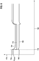
- FIG. 3 shows a second example of a time profile of electrical voltages and measurement signals in the case of the sensor 100 with a defective fourth electrically conductive connection 146. Only the differences from that in FIG Figure 4 The example shown is explained and the same components or features are provided with the same reference numerals.
- the fourth electrically conductive connection 146 is identified as defective if the measurement signal 174 has a change for the predetermined time. If there is an interruption in the fourth electrically conductive connection 146, the change in voltage at COM causes a significant flow of current on the fourth electrically conductive connection 146 via the measuring resistor 160.
- the example shown is an open circuit, so that the measurement signal 174 from the point in time 178 has a clear drop 180 for the predetermined time.
- FIG. 3 shows a third example of a time profile of electrical voltages and measurement signals in the case of the sensor 100 with the fourth electrically conductive connection 146 intact.
- the time is plotted on the X axis 168.
- the electrical voltage U P2 applied to the second pump cell 140, the predetermined electrical voltage U COM applied to the common terminal COM and a difference 182 between the electrical voltage applied to the second pump cell 140 Voltage U P2 and the predetermined electrical voltage U COM are plotted.
- Curve 172 represents the time profile of the predetermined electrical voltage U COM
- curve 184 shows the time profile of the electrical voltage U P2 applied to second pump cell 140
- curve 186 represents measurement signal 174 in the form of the time profile of the difference 182 between the electrical voltage U P2 applied to the second pump cell 140 and the predetermined electrical voltage U COM
- the control unit 122 changes the predetermined electrical voltage U COM for a predetermined time to generate a measurement signal.
- the predetermined time is 0.08 ms to 1 ms, and preferably 0.5 ms to 1 ms.
- the predetermined time is 1 ms.
- the predetermined electrical voltage U COM is lowered for the predetermined time at time 178 such that a voltage difference U P2 between the second separate terminal P2 and the common terminal COM of 450 mV to 2500 mV and preferably 460 mV to 1500 mV is formed.
- a voltage difference U P2 of 750 mV is formed.
- a sufficiently large one must open between the pump electrode 142 and the counter electrode 144 a fixed value regulated voltage U P2 is present.
- This voltage U P2 at the second pump cell 140 can be, for example, 450 mV against COM.
- the fourth electrically conductive connection 146 is identified as intact if the measurement signal 174 shows no change for the predetermined time, ie the difference 182 is 450 mV.
- the current can flow through the sensor element 110 via the sensor element 110, the charge reversal processes caused by the hardware circuit of the control unit 122 to lower the predetermined electrical voltage U COM, and the voltage change can be caused by the operational amplifier 158 set voltage within a very short time of, for example, 10 to 15 ⁇ S, depending on the aging of the second pump cell 140 or manufacturing tolerances, follow the desired 450 mV.
- the operational amplifier 158 set voltage within a very short time of, for example, 10 to 15 ⁇ S, depending on the aging of the second pump cell 140 or manufacturing tolerances, follow the desired 450 mV.
- there is a closed circuit and thus an intact fourth electrically conductive connection 146 so that the measurement signal 174 from the time 178 with an insignificant delay of 15 to 20 ⁇ S after lowering the predetermined electrical voltage U COM unchanged for the predetermined Time is.
- FIG. 4 shows a fourth example of a time profile of electrical voltages and measurement signals in the case of the sensor 100 with a defective fourth electrically conductive connection 146. Only the differences from that in FIG Figure 6 The example shown is explained and the same components or features are provided with the same reference numerals.
- the fourth electrically conductive connection 146 is identified as defective if the measurement signal 168 exhibits a change for the predetermined time. If there is an interruption in the fourth electrically conductive connection 146, the change in voltage at COM causes a significant flow of current on the fourth electrically conductive connection 146 via the measuring resistor 160.
- the measurement signal 174 from time 178 has a significantly higher potential of, for example, 750 mV instead of 450 mV in the normal case for the predetermined time. It is explicitly emphasized that for the assessment of the state of the fourth electrically conductive connection an observation of the time profile of the electrical voltage U P2 applied to the second pump cell 140 is sufficient without the difference 182 having to be considered.
Landscapes
- Chemical & Material Sciences (AREA)
- Life Sciences & Earth Sciences (AREA)
- Health & Medical Sciences (AREA)
- Biochemistry (AREA)
- Chemical Kinetics & Catalysis (AREA)
- Electrochemistry (AREA)
- Physics & Mathematics (AREA)
- Analytical Chemistry (AREA)
- Molecular Biology (AREA)
- General Health & Medical Sciences (AREA)
- General Physics & Mathematics (AREA)
- Immunology (AREA)
- Pathology (AREA)
- Investigating Or Analyzing Materials By The Use Of Electric Means (AREA)
- Measuring Oxygen Concentration In Cells (AREA)
- Combined Controls Of Internal Combustion Engines (AREA)
Claims (5)
- Procédé permettant de faire fonctionner un capteur (100) pour détecter au moins une fraction d'un composant de gaz de mesure avec de l'oxygène lié dans un gaz de mesure, en particulier dans un gaz d'échappement d'un moteur à combustion interne, comprenant un élément capteur (110), l'élément capteur (110) présentant une première cellule de pompage (112) qui présente une électrode de pompage extérieure (114) et une électrode de pompage intérieure (116) et qui est adjacente à une première cavité (126) qui est en communication avec le gaz de mesure, une cellule de référence (130) qui présente une électrode de Nernst (132) et une électrode de référence (134) et qui est adjacente à une chambre à gaz de référence (138), et une deuxième cellule de pompage (140) qui présente une électrode de pompage (142) et une contre-électrode (144) et qui est adjacente à une deuxième cavité (145), un appareil de commande électronique (122), qui dispose au moins d'une première borne séparée (P1) pour la première cellule de pompage (112), d'une deuxième borne séparée (P2) pour la deuxième cellule de pompage (140), d'une borne pour une tension de Nernst (Vs) et d'une borne commune (COM), étant relié à l'élément capteur (110), l'électrode de pompage extérieure (114) étant reliée à la première borne séparée (P1) au moyen d'une première liaison électriquement conductrice (120), l'électrode de pompage intérieure (116) étant reliée à la borne commune (COM) au moyen d'une deuxième liaison électriquement conductrice (124), l'électrode de référence (134) étant reliée à la borne pour une tension de Nernst (Vs) au moyen d'une troisième liaison électriquement conductrice (136), l'électrode de pompage (142) étant reliée à la borne commune (COM) au moyen de la deuxième liaison électriquement conductrice (124), la contre-électrode (144) étant reliée à la deuxième borne séparée (P2) au moyen d'une quatrième liaison électriquement conductrice (146), une résistance de mesure (160) étant prévue dans la quatrième liaison électriquement conductrice (146), une tension électrique prédéterminée (UCOM) étant appliquée à la borne commune (COM), la quatrième liaison électriquement conductrice (146) entre la résistance de mesure (160) et la deuxième cellule de pompage (140) étant reliée à un condensateur (162) qui est en outre relié à une masse (GND) de l'appareil de commande (122), dans lequel, au moyen de l'appareil de commande (122), une variation de la tension électrique prédéterminée (UCOM) est effectuée pendant une durée prédéterminée pour générer un signal de mesure (168), le signal de mesure (168) étant donné par la courbe dans le temps d'une chute de tension (UIP2) aux bornes de la résistance de mesure (160) ou par la courbe dans le temps d'une différence (182) entre une tension électrique (UP2) appliquée à la deuxième cellule de pompage (140) et la tension électrique prédéterminée (UCOM), la quatrième liaison électriquement conductrice (146) étant identifiée comme étant intacte si le signal de mesure (168) ne présente aucune variation pendant la durée prédéterminée, et étant identifiée comme étant défectueuse si le signal de mesure (168) présente une variation pendant la durée prédéterminée.
- Procédé selon la revendication 1, dans lequel la durée prédéterminée est comprise entre 0,08 ms et 1 ms et de préférence entre 0,5 ms et 1 ms.
- Procédé selon la revendication 1 ou 2, dans lequel la tension électrique prédéterminée (UCOM) est abaissée pendant la durée prédéterminée.
- Procédé selon la revendication 3, dans lequel la tension électrique prédéterminée (UCOM) est abaissée pendant la durée prédéterminée de telle sorte qu'une différence de tension (UP2) entre la deuxième borne séparée (P2) et la borne commune (COM) de 450 mV à 1,2 V se forme.
- Procédé selon la revendication 3, dans lequel la tension électrique prédéterminée (UCOM) est abaissée pendant la durée prédéterminée de telle sorte qu'une différence de tension (UP2) entre la deuxième borne séparée (P2) et la borne commune (COM) de 450 mV à 1500 mV et de préférence de 600 mV à 1300 mV se forme.
Applications Claiming Priority (2)
| Application Number | Priority Date | Filing Date | Title |
|---|---|---|---|
| DE102018206765.1A DE102018206765A1 (de) | 2018-05-02 | 2018-05-02 | Verfahren zum Betreiben eines Sensors zum Nachweis mindestens eines Anteils einer Messgaskomponente mit gebundenem Sauerstoff in einem Messgas |
| PCT/EP2019/060712 WO2019211182A1 (fr) | 2018-05-02 | 2019-04-26 | Procédé de fonctionnement d'un capteur pour détecter au moins une fraction d'un composant gazeux mesuré, lié à de l'oxygène, dans un gaz de mesure |
Publications (2)
| Publication Number | Publication Date |
|---|---|
| EP3788356A1 EP3788356A1 (fr) | 2021-03-10 |
| EP3788356B1 true EP3788356B1 (fr) | 2021-12-22 |
Family
ID=66334455
Family Applications (1)
| Application Number | Title | Priority Date | Filing Date |
|---|---|---|---|
| EP19720540.4A Active EP3788356B1 (fr) | 2018-05-02 | 2019-04-26 | Procédé de fonctionnement d'un capteur pour détecter au moins une fraction d'un composant gazeux mesuré, lié à de l'oxygène, dans un gaz de mesure |
Country Status (5)
| Country | Link |
|---|---|
| EP (1) | EP3788356B1 (fr) |
| CN (1) | CN112384795B (fr) |
| DE (1) | DE102018206765A1 (fr) |
| ES (1) | ES2908886T3 (fr) |
| WO (1) | WO2019211182A1 (fr) |
Families Citing this family (1)
| Publication number | Priority date | Publication date | Assignee | Title |
|---|---|---|---|---|
| DE102022210329A1 (de) * | 2022-09-29 | 2024-04-04 | Robert Bosch Gesellschaft mit beschränkter Haftung | Verfahren zum Betreiben eines Sensors zum Nachweis mindestens eines Anteils einer Messgaskomponente mit gebundenem Sauerstoff in einem Messgas |
Family Cites Families (8)
| Publication number | Priority date | Publication date | Assignee | Title |
|---|---|---|---|---|
| DE10049685A1 (de) * | 2000-10-07 | 2002-04-11 | Volkswagen Ag | Verfahren und Vorrichtung zur Eigendiagnose eines NOX-Sensors |
| DE102004016986B3 (de) * | 2004-04-02 | 2005-10-06 | Siemens Ag | Vorrichtung und Verfahren zur Messung mehrerer Abgasbestandteile |
| DE102006061954A1 (de) * | 2006-12-29 | 2008-07-03 | Robert Bosch Gmbh | Sensorelement mit zusätzlicher Fettgasregelung |
| US9518954B2 (en) * | 2007-11-05 | 2016-12-13 | Ngk Spark Plug Co., Ltd. | Gas sensor control device |
| DE102007062800A1 (de) * | 2007-12-27 | 2009-07-02 | Robert Bosch Gmbh | Verfahren zur Bestimmung einer Gaszusammensetzung in einem Messgasraum |
| DE102015210473A1 (de) * | 2014-09-11 | 2016-03-17 | Robert Bosch Gmbh | Verfahren und Vorrichtung zum Nachweis mindestens eines Anteils der Messgaskomponente mit gebundenem Sauerstoff in einem Gasgemisch |
| DE102014224943A1 (de) * | 2014-12-04 | 2016-06-09 | Robert Bosch Gmbh | Verfahren zur Erkennung von mindestens zwei Arten von elektrischen Fehlern in mindestens einem Stromkreis |
| EP3064937B1 (fr) * | 2015-03-06 | 2021-02-24 | Elster GmbH | Procédé de fonctionnement d'une sonde lambda large bande |
-
2018
- 2018-05-02 DE DE102018206765.1A patent/DE102018206765A1/de active Pending
-
2019
- 2019-04-26 EP EP19720540.4A patent/EP3788356B1/fr active Active
- 2019-04-26 ES ES19720540T patent/ES2908886T3/es active Active
- 2019-04-26 CN CN201980044669.1A patent/CN112384795B/zh active Active
- 2019-04-26 WO PCT/EP2019/060712 patent/WO2019211182A1/fr not_active Ceased
Also Published As
| Publication number | Publication date |
|---|---|
| EP3788356A1 (fr) | 2021-03-10 |
| CN112384795B (zh) | 2023-11-21 |
| WO2019211182A1 (fr) | 2019-11-07 |
| DE102018206765A1 (de) | 2019-11-07 |
| CN112384795A (zh) | 2021-02-19 |
| ES2908886T3 (es) | 2022-05-04 |
Similar Documents
| Publication | Publication Date | Title |
|---|---|---|
| DE69821410T2 (de) | Gassensor | |
| DE10339684B4 (de) | Gassensor-Störungsermittlungsvorrichtung zur Erfassung des Vorliegens oder Nichtvorliegens eines Störzustands eines Gassensors mit einer Vielzahl von Zellen | |
| DE69734140T2 (de) | Gas Sensor | |
| EP1616174B1 (fr) | Procede permettant de faire fonctionner un detecteur de gaz | |
| EP3596453B1 (fr) | Procédé de fonctionnement d'un capteur de détection d'au moins une propriété d'un gaz à mesurer dans un espace de gaz à mesurer | |
| DE10392160T5 (de) | NOx-Konzentrationsmessvorrichtung und Vorrichtung zur Selbstdiagnose eines NOx-Sensors sowie Selbstdiagnoseverfahren dafür | |
| WO2016165997A1 (fr) | Procédé de fonctionnement d'un capteur de détection d'au moins une caractéristique d'un gaz à mesurer dans un espace de gaz à mesurer | |
| EP3788356B1 (fr) | Procédé de fonctionnement d'un capteur pour détecter au moins une fraction d'un composant gazeux mesuré, lié à de l'oxygène, dans un gaz de mesure | |
| WO2019170639A1 (fr) | Procédé de fonctionnement d'un capteur pour détecter au moins une fraction d'un composant gazeux mesuré, lié à de l'oxygène, dans un gaz de mesure | |
| WO2024068533A1 (fr) | Procédé de diagnostic pour faire fonctionner un capteur pour détecter au moins une partie d'un composant de gaz de mesure comprenant de l'oxygène lié dans un gaz de mesure | |
| DE102018203313A1 (de) | Verfahren zum Betreiben eines Sensors zum Nachweis mindestens eines Anteils einer Messgaskomponente mit gebundenem Sauerstoff in einem Messgas | |
| DE19803532A1 (de) | Elektrochemischer Meßfühler | |
| EP3818366B1 (fr) | Procédé pour faire fonctionner un capteur destiné à détecter au moins une fraction d'un composant d'un gaz de mesure avec de l'oxygène lié dans un gaz de mesure | |
| EP3622281B1 (fr) | Procédé de détermination de la température d'un capteur de gaz à électrolyte solide | |
| DE102012224374A1 (de) | Verfahren zur Diagnose einer elektrischen Leitung zu einer Elektrode eines Sensorelements zur Erfassung mindestens einer Eigenschaft eines Messgases in einem Messgasraum | |
| DE102016215881A1 (de) | Verfahren zur Durchführung eines Erholungsprozesses von Gassensoren | |
| DE102011003514A1 (de) | Verfahren und Überwachungsgerät zur Überwachung zumindest einer Funktion eines chemosensitiven Feldeffekttransistors | |
| EP3818367B1 (fr) | Procédé pour faire fonctionner un capteur destiné à détecter au moins une fraction d'un composant d'un gaz de mesure avec de l'oxygène lié dans un gaz de mesure | |
| EP3899520B1 (fr) | Procédé de réduction d'erreurs de mesure lors de la détection d'ammoniac lors du fonctionnement d'un système de capteur | |
| DE102015201396A1 (de) | Sensor zur Erfassung mindestens einer Eigenschaft eines Messgases in einem Messgasraum | |
| EP4139670B1 (fr) | Procédé de détermination d'une concentration d'oxygène dans un gaz résiduaire | |
| DE102013216227A1 (de) | Kapazitive Eigendiagnose des Elektrodensystems eines Partikelsensors | |
| WO2019120789A1 (fr) | Dispositif capteur pour la détection de particules d'un gaz de mesure dans un espace de gaz de mesure et procédé de détection de particules d'un gaz de mesure dans un espace de gaz de mesure | |
| WO2023099253A1 (fr) | Procédé d'activation d'un capteur permettant de déterminer au moins une proportion d'un gaz dans une chambre de gaz de mesure | |
| DE102020208880A1 (de) | Verfahren zum Betreiben eines Sensors zur Erfassung mindestens einer Eigenschaft eines Messgases in einem Messgasraum |
Legal Events
| Date | Code | Title | Description |
|---|---|---|---|
| STAA | Information on the status of an ep patent application or granted ep patent |
Free format text: STATUS: UNKNOWN |
|
| STAA | Information on the status of an ep patent application or granted ep patent |
Free format text: STATUS: THE INTERNATIONAL PUBLICATION HAS BEEN MADE |
|
| PUAI | Public reference made under article 153(3) epc to a published international application that has entered the european phase |
Free format text: ORIGINAL CODE: 0009012 |
|
| STAA | Information on the status of an ep patent application or granted ep patent |
Free format text: STATUS: REQUEST FOR EXAMINATION WAS MADE |
|
| 17P | Request for examination filed |
Effective date: 20201202 |
|
| AK | Designated contracting states |
Kind code of ref document: A1 Designated state(s): AL AT BE BG CH CY CZ DE DK EE ES FI FR GB GR HR HU IE IS IT LI LT LU LV MC MK MT NL NO PL PT RO RS SE SI SK SM TR |
|
| AX | Request for extension of the european patent |
Extension state: BA ME |
|
| DAV | Request for validation of the european patent (deleted) | ||
| DAX | Request for extension of the european patent (deleted) | ||
| REG | Reference to a national code |
Ref country code: DE Ref legal event code: R079 Ref document number: 502019003067 Country of ref document: DE Free format text: PREVIOUS MAIN CLASS: G01N0027419000 Ipc: G01N0027417000 |
|
| GRAP | Despatch of communication of intention to grant a patent |
Free format text: ORIGINAL CODE: EPIDOSNIGR1 |
|
| STAA | Information on the status of an ep patent application or granted ep patent |
Free format text: STATUS: GRANT OF PATENT IS INTENDED |
|
| RIC1 | Information provided on ipc code assigned before grant |
Ipc: G01N 27/417 20060101AFI20210827BHEP |
|
| INTG | Intention to grant announced |
Effective date: 20210913 |
|
| GRAS | Grant fee paid |
Free format text: ORIGINAL CODE: EPIDOSNIGR3 |
|
| GRAA | (expected) grant |
Free format text: ORIGINAL CODE: 0009210 |
|
| STAA | Information on the status of an ep patent application or granted ep patent |
Free format text: STATUS: THE PATENT HAS BEEN GRANTED |
|
| AK | Designated contracting states |
Kind code of ref document: B1 Designated state(s): AL AT BE BG CH CY CZ DE DK EE ES FI FR GB GR HR HU IE IS IT LI LT LU LV MC MK MT NL NO PL PT RO RS SE SI SK SM TR |
|
| REG | Reference to a national code |
Ref country code: GB Ref legal event code: FG4D Free format text: NOT ENGLISH |
|
| REG | Reference to a national code |
Ref country code: CH Ref legal event code: EP |
|
| REG | Reference to a national code |
Ref country code: DE Ref legal event code: R096 Ref document number: 502019003067 Country of ref document: DE |
|
| REG | Reference to a national code |
Ref country code: AT Ref legal event code: REF Ref document number: 1457387 Country of ref document: AT Kind code of ref document: T Effective date: 20220115 |
|
| REG | Reference to a national code |
Ref country code: IE Ref legal event code: FG4D Free format text: LANGUAGE OF EP DOCUMENT: GERMAN |
|
| REG | Reference to a national code |
Ref country code: LT Ref legal event code: MG9D |
|
| PG25 | Lapsed in a contracting state [announced via postgrant information from national office to epo] |
Ref country code: RS Free format text: LAPSE BECAUSE OF FAILURE TO SUBMIT A TRANSLATION OF THE DESCRIPTION OR TO PAY THE FEE WITHIN THE PRESCRIBED TIME-LIMIT Effective date: 20211222 Ref country code: LT Free format text: LAPSE BECAUSE OF FAILURE TO SUBMIT A TRANSLATION OF THE DESCRIPTION OR TO PAY THE FEE WITHIN THE PRESCRIBED TIME-LIMIT Effective date: 20211222 Ref country code: FI Free format text: LAPSE BECAUSE OF FAILURE TO SUBMIT A TRANSLATION OF THE DESCRIPTION OR TO PAY THE FEE WITHIN THE PRESCRIBED TIME-LIMIT Effective date: 20211222 Ref country code: BG Free format text: LAPSE BECAUSE OF FAILURE TO SUBMIT A TRANSLATION OF THE DESCRIPTION OR TO PAY THE FEE WITHIN THE PRESCRIBED TIME-LIMIT Effective date: 20220322 |
|
| REG | Reference to a national code |
Ref country code: NL Ref legal event code: MP Effective date: 20211222 |
|
| REG | Reference to a national code |
Ref country code: ES Ref legal event code: FG2A Ref document number: 2908886 Country of ref document: ES Kind code of ref document: T3 Effective date: 20220504 |
|
| PG25 | Lapsed in a contracting state [announced via postgrant information from national office to epo] |
Ref country code: SE Free format text: LAPSE BECAUSE OF FAILURE TO SUBMIT A TRANSLATION OF THE DESCRIPTION OR TO PAY THE FEE WITHIN THE PRESCRIBED TIME-LIMIT Effective date: 20211222 Ref country code: NO Free format text: LAPSE BECAUSE OF FAILURE TO SUBMIT A TRANSLATION OF THE DESCRIPTION OR TO PAY THE FEE WITHIN THE PRESCRIBED TIME-LIMIT Effective date: 20220322 Ref country code: LV Free format text: LAPSE BECAUSE OF FAILURE TO SUBMIT A TRANSLATION OF THE DESCRIPTION OR TO PAY THE FEE WITHIN THE PRESCRIBED TIME-LIMIT Effective date: 20211222 Ref country code: HR Free format text: LAPSE BECAUSE OF FAILURE TO SUBMIT A TRANSLATION OF THE DESCRIPTION OR TO PAY THE FEE WITHIN THE PRESCRIBED TIME-LIMIT Effective date: 20211222 Ref country code: GR Free format text: LAPSE BECAUSE OF FAILURE TO SUBMIT A TRANSLATION OF THE DESCRIPTION OR TO PAY THE FEE WITHIN THE PRESCRIBED TIME-LIMIT Effective date: 20220323 |
|
| PG25 | Lapsed in a contracting state [announced via postgrant information from national office to epo] |
Ref country code: NL Free format text: LAPSE BECAUSE OF FAILURE TO SUBMIT A TRANSLATION OF THE DESCRIPTION OR TO PAY THE FEE WITHIN THE PRESCRIBED TIME-LIMIT Effective date: 20211222 |
|
| PG25 | Lapsed in a contracting state [announced via postgrant information from national office to epo] |
Ref country code: SM Free format text: LAPSE BECAUSE OF FAILURE TO SUBMIT A TRANSLATION OF THE DESCRIPTION OR TO PAY THE FEE WITHIN THE PRESCRIBED TIME-LIMIT Effective date: 20211222 Ref country code: SK Free format text: LAPSE BECAUSE OF FAILURE TO SUBMIT A TRANSLATION OF THE DESCRIPTION OR TO PAY THE FEE WITHIN THE PRESCRIBED TIME-LIMIT Effective date: 20211222 Ref country code: RO Free format text: LAPSE BECAUSE OF FAILURE TO SUBMIT A TRANSLATION OF THE DESCRIPTION OR TO PAY THE FEE WITHIN THE PRESCRIBED TIME-LIMIT Effective date: 20211222 Ref country code: PT Free format text: LAPSE BECAUSE OF FAILURE TO SUBMIT A TRANSLATION OF THE DESCRIPTION OR TO PAY THE FEE WITHIN THE PRESCRIBED TIME-LIMIT Effective date: 20220422 Ref country code: EE Free format text: LAPSE BECAUSE OF FAILURE TO SUBMIT A TRANSLATION OF THE DESCRIPTION OR TO PAY THE FEE WITHIN THE PRESCRIBED TIME-LIMIT Effective date: 20211222 Ref country code: CZ Free format text: LAPSE BECAUSE OF FAILURE TO SUBMIT A TRANSLATION OF THE DESCRIPTION OR TO PAY THE FEE WITHIN THE PRESCRIBED TIME-LIMIT Effective date: 20211222 |
|
| PG25 | Lapsed in a contracting state [announced via postgrant information from national office to epo] |
Ref country code: PL Free format text: LAPSE BECAUSE OF FAILURE TO SUBMIT A TRANSLATION OF THE DESCRIPTION OR TO PAY THE FEE WITHIN THE PRESCRIBED TIME-LIMIT Effective date: 20211222 |
|
| REG | Reference to a national code |
Ref country code: DE Ref legal event code: R097 Ref document number: 502019003067 Country of ref document: DE |
|
| PG25 | Lapsed in a contracting state [announced via postgrant information from national office to epo] |
Ref country code: IS Free format text: LAPSE BECAUSE OF FAILURE TO SUBMIT A TRANSLATION OF THE DESCRIPTION OR TO PAY THE FEE WITHIN THE PRESCRIBED TIME-LIMIT Effective date: 20220422 |
|
| PLBE | No opposition filed within time limit |
Free format text: ORIGINAL CODE: 0009261 |
|
| STAA | Information on the status of an ep patent application or granted ep patent |
Free format text: STATUS: NO OPPOSITION FILED WITHIN TIME LIMIT |
|
| PG25 | Lapsed in a contracting state [announced via postgrant information from national office to epo] |
Ref country code: DK Free format text: LAPSE BECAUSE OF FAILURE TO SUBMIT A TRANSLATION OF THE DESCRIPTION OR TO PAY THE FEE WITHIN THE PRESCRIBED TIME-LIMIT Effective date: 20211222 Ref country code: AL Free format text: LAPSE BECAUSE OF FAILURE TO SUBMIT A TRANSLATION OF THE DESCRIPTION OR TO PAY THE FEE WITHIN THE PRESCRIBED TIME-LIMIT Effective date: 20211222 |
|
| 26N | No opposition filed |
Effective date: 20220923 |
|
| REG | Reference to a national code |
Ref country code: CH Ref legal event code: PL |
|
| REG | Reference to a national code |
Ref country code: BE Ref legal event code: MM Effective date: 20220430 |
|
| PG25 | Lapsed in a contracting state [announced via postgrant information from national office to epo] |
Ref country code: MC Free format text: LAPSE BECAUSE OF FAILURE TO SUBMIT A TRANSLATION OF THE DESCRIPTION OR TO PAY THE FEE WITHIN THE PRESCRIBED TIME-LIMIT Effective date: 20211222 Ref country code: LU Free format text: LAPSE BECAUSE OF NON-PAYMENT OF DUE FEES Effective date: 20220426 Ref country code: LI Free format text: LAPSE BECAUSE OF NON-PAYMENT OF DUE FEES Effective date: 20220430 Ref country code: CH Free format text: LAPSE BECAUSE OF NON-PAYMENT OF DUE FEES Effective date: 20220430 |
|
| PG25 | Lapsed in a contracting state [announced via postgrant information from national office to epo] |
Ref country code: SI Free format text: LAPSE BECAUSE OF FAILURE TO SUBMIT A TRANSLATION OF THE DESCRIPTION OR TO PAY THE FEE WITHIN THE PRESCRIBED TIME-LIMIT Effective date: 20211222 Ref country code: BE Free format text: LAPSE BECAUSE OF NON-PAYMENT OF DUE FEES Effective date: 20220430 |
|
| PG25 | Lapsed in a contracting state [announced via postgrant information from national office to epo] |
Ref country code: IE Free format text: LAPSE BECAUSE OF NON-PAYMENT OF DUE FEES Effective date: 20220426 |
|
| PG25 | Lapsed in a contracting state [announced via postgrant information from national office to epo] |
Ref country code: IT Free format text: LAPSE BECAUSE OF FAILURE TO SUBMIT A TRANSLATION OF THE DESCRIPTION OR TO PAY THE FEE WITHIN THE PRESCRIBED TIME-LIMIT Effective date: 20211222 |
|
| PG25 | Lapsed in a contracting state [announced via postgrant information from national office to epo] |
Ref country code: MK Free format text: LAPSE BECAUSE OF FAILURE TO SUBMIT A TRANSLATION OF THE DESCRIPTION OR TO PAY THE FEE WITHIN THE PRESCRIBED TIME-LIMIT Effective date: 20211222 Ref country code: CY Free format text: LAPSE BECAUSE OF FAILURE TO SUBMIT A TRANSLATION OF THE DESCRIPTION OR TO PAY THE FEE WITHIN THE PRESCRIBED TIME-LIMIT Effective date: 20211222 |
|
| PG25 | Lapsed in a contracting state [announced via postgrant information from national office to epo] |
Ref country code: HU Free format text: LAPSE BECAUSE OF FAILURE TO SUBMIT A TRANSLATION OF THE DESCRIPTION OR TO PAY THE FEE WITHIN THE PRESCRIBED TIME-LIMIT; INVALID AB INITIO Effective date: 20190426 |
|
| PG25 | Lapsed in a contracting state [announced via postgrant information from national office to epo] |
Ref country code: MT Free format text: LAPSE BECAUSE OF FAILURE TO SUBMIT A TRANSLATION OF THE DESCRIPTION OR TO PAY THE FEE WITHIN THE PRESCRIBED TIME-LIMIT Effective date: 20211222 |
|
| REG | Reference to a national code |
Ref country code: AT Ref legal event code: MM01 Ref document number: 1457387 Country of ref document: AT Kind code of ref document: T Effective date: 20240426 |
|
| PGFP | Annual fee paid to national office [announced via postgrant information from national office to epo] |
Ref country code: DE Payment date: 20250624 Year of fee payment: 7 |
|
| PGFP | Annual fee paid to national office [announced via postgrant information from national office to epo] |
Ref country code: ES Payment date: 20250519 Year of fee payment: 7 |
|
| PGFP | Annual fee paid to national office [announced via postgrant information from national office to epo] |
Ref country code: FR Payment date: 20250422 Year of fee payment: 7 |
|
| PG25 | Lapsed in a contracting state [announced via postgrant information from national office to epo] |
Ref country code: AT Free format text: LAPSE BECAUSE OF NON-PAYMENT OF DUE FEES Effective date: 20240426 |
|
| PG25 | Lapsed in a contracting state [announced via postgrant information from national office to epo] |
Ref country code: TR Free format text: LAPSE BECAUSE OF FAILURE TO SUBMIT A TRANSLATION OF THE DESCRIPTION OR TO PAY THE FEE WITHIN THE PRESCRIBED TIME-LIMIT Effective date: 20211222 |
|
| PGFP | Annual fee paid to national office [announced via postgrant information from national office to epo] |
Ref country code: GB Payment date: 20260324 Year of fee payment: 8 |
|
| PGFP | Annual fee paid to national office [announced via postgrant information from national office to epo] |
Ref country code: AT Payment date: 20260410 Year of fee payment: 5 |