EP3789123B1 - Dispositif d'enduction et procédé d'enduction - Google Patents
Dispositif d'enduction et procédé d'enduction Download PDFInfo
- Publication number
- EP3789123B1 EP3789123B1 EP19850781.6A EP19850781A EP3789123B1 EP 3789123 B1 EP3789123 B1 EP 3789123B1 EP 19850781 A EP19850781 A EP 19850781A EP 3789123 B1 EP3789123 B1 EP 3789123B1
- Authority
- EP
- European Patent Office
- Prior art keywords
- coating
- region
- overlapping
- subdivided
- coating region
- Prior art date
- Legal status (The legal status is an assumption and is not a legal conclusion. Google has not performed a legal analysis and makes no representation as to the accuracy of the status listed.)
- Active
Links
Images





Classifications
-
- B—PERFORMING OPERATIONS; TRANSPORTING
- B41—PRINTING; LINING MACHINES; TYPEWRITERS; STAMPS
- B41J—TYPEWRITERS; SELECTIVE PRINTING MECHANISMS, i.e. MECHANISMS PRINTING OTHERWISE THAN FROM A FORME; CORRECTION OF TYPOGRAPHICAL ERRORS
- B41J2/00—Typewriters or selective printing mechanisms characterised by the printing or marking process for which they are designed
- B41J2/005—Typewriters or selective printing mechanisms characterised by the printing or marking process for which they are designed characterised by bringing liquid or particles selectively into contact with a printing material
- B41J2/01—Ink jet
- B41J2/135—Nozzles
- B41J2/145—Arrangement thereof
-
- B—PERFORMING OPERATIONS; TRANSPORTING
- B41—PRINTING; LINING MACHINES; TYPEWRITERS; STAMPS
- B41J—TYPEWRITERS; SELECTIVE PRINTING MECHANISMS, i.e. MECHANISMS PRINTING OTHERWISE THAN FROM A FORME; CORRECTION OF TYPOGRAPHICAL ERRORS
- B41J2/00—Typewriters or selective printing mechanisms characterised by the printing or marking process for which they are designed
- B41J2/005—Typewriters or selective printing mechanisms characterised by the printing or marking process for which they are designed characterised by bringing liquid or particles selectively into contact with a printing material
- B41J2/01—Ink jet
- B41J2/135—Nozzles
- B41J2/14—Structure thereof only for on-demand ink jet heads
- B41J2/14201—Structure of print heads with piezoelectric elements
- B41J2/14209—Structure of print heads with piezoelectric elements of finger type, chamber walls consisting integrally of piezoelectric material
-
- B—PERFORMING OPERATIONS; TRANSPORTING
- B05—SPRAYING OR ATOMISING IN GENERAL; APPLYING FLUENT MATERIALS TO SURFACES, IN GENERAL
- B05B—SPRAYING APPARATUS; ATOMISING APPARATUS; NOZZLES
- B05B1/00—Nozzles, spray heads or other outlets, with or without auxiliary devices such as valves, heating means
- B05B1/14—Nozzles, spray heads or other outlets, with or without auxiliary devices such as valves, heating means with multiple outlet openings; with strainers in or outside the outlet opening
-
- B—PERFORMING OPERATIONS; TRANSPORTING
- B05—SPRAYING OR ATOMISING IN GENERAL; APPLYING FLUENT MATERIALS TO SURFACES, IN GENERAL
- B05B—SPRAYING APPARATUS; ATOMISING APPARATUS; NOZZLES
- B05B12/00—Arrangements for controlling delivery; Arrangements for controlling the spray area
- B05B12/08—Arrangements for controlling delivery; Arrangements for controlling the spray area responsive to condition of liquid or other fluent material to be discharged, of ambient medium or of target ; responsive to condition of spray devices or of supply means, e.g. pipes, pumps or their drive means
- B05B12/084—Arrangements for controlling delivery; Arrangements for controlling the spray area responsive to condition of liquid or other fluent material to be discharged, of ambient medium or of target ; responsive to condition of spray devices or of supply means, e.g. pipes, pumps or their drive means responsive to condition of liquid or other fluent material already sprayed on the target, e.g. coating thickness, weight or pattern
-
- B—PERFORMING OPERATIONS; TRANSPORTING
- B05—SPRAYING OR ATOMISING IN GENERAL; APPLYING FLUENT MATERIALS TO SURFACES, IN GENERAL
- B05B—SPRAYING APPARATUS; ATOMISING APPARATUS; NOZZLES
- B05B13/00—Machines or plants for applying liquids or other fluent materials to surfaces of objects or other work by spraying, not covered by groups B05B1/00 - B05B11/00
- B05B13/002—Machines or plants for applying coating liquids or other fluent materials by inkjet
-
- B—PERFORMING OPERATIONS; TRANSPORTING
- B05—SPRAYING OR ATOMISING IN GENERAL; APPLYING FLUENT MATERIALS TO SURFACES, IN GENERAL
- B05B—SPRAYING APPARATUS; ATOMISING APPARATUS; NOZZLES
- B05B13/00—Machines or plants for applying liquids or other fluent materials to surfaces of objects or other work by spraying, not covered by groups B05B1/00 - B05B11/00
- B05B13/02—Means for supporting work; Arrangement or mounting of spray heads; Adaptation or arrangement of means for feeding work
- B05B13/04—Means for supporting work; Arrangement or mounting of spray heads; Adaptation or arrangement of means for feeding work the spray heads being moved during spraying operation
- B05B13/0431—Means for supporting work; Arrangement or mounting of spray heads; Adaptation or arrangement of means for feeding work the spray heads being moved during spraying operation with spray heads moved by robots or articulated arms, e.g. for applying liquid or other fluent material to three-dimensional [3D] surfaces
-
- B—PERFORMING OPERATIONS; TRANSPORTING
- B05—SPRAYING OR ATOMISING IN GENERAL; APPLYING FLUENT MATERIALS TO SURFACES, IN GENERAL
- B05B—SPRAYING APPARATUS; ATOMISING APPARATUS; NOZZLES
- B05B17/00—Apparatus for spraying or atomising liquids or other fluent materials, not covered by the preceding groups
- B05B17/04—Apparatus for spraying or atomising liquids or other fluent materials, not covered by the preceding groups operating with special methods
- B05B17/06—Apparatus for spraying or atomising liquids or other fluent materials, not covered by the preceding groups operating with special methods using ultrasonic or other kinds of vibrations
- B05B17/0607—Apparatus for spraying or atomising liquids or other fluent materials, not covered by the preceding groups operating with special methods using ultrasonic or other kinds of vibrations generated by electrical means, e.g. piezoelectric transducers
-
- B—PERFORMING OPERATIONS; TRANSPORTING
- B25—HAND TOOLS; PORTABLE POWER-DRIVEN TOOLS; MANIPULATORS
- B25J—MANIPULATORS; CHAMBERS PROVIDED WITH MANIPULATION DEVICES
- B25J11/00—Manipulators not otherwise provided for
- B25J11/0075—Manipulators for painting or coating
-
- B—PERFORMING OPERATIONS; TRANSPORTING
- B41—PRINTING; LINING MACHINES; TYPEWRITERS; STAMPS
- B41J—TYPEWRITERS; SELECTIVE PRINTING MECHANISMS, i.e. MECHANISMS PRINTING OTHERWISE THAN FROM A FORME; CORRECTION OF TYPOGRAPHICAL ERRORS
- B41J3/00—Typewriters or selective printing or marking mechanisms characterised by the purpose for which they are constructed
- B41J3/407—Typewriters or selective printing or marking mechanisms characterised by the purpose for which they are constructed for marking on special material
- B41J3/4073—Printing on three-dimensional objects not being in sheet or web form, e.g. spherical or cubic objects
-
- B—PERFORMING OPERATIONS; TRANSPORTING
- B05—SPRAYING OR ATOMISING IN GENERAL; APPLYING FLUENT MATERIALS TO SURFACES, IN GENERAL
- B05B—SPRAYING APPARATUS; ATOMISING APPARATUS; NOZZLES
- B05B1/00—Nozzles, spray heads or other outlets, with or without auxiliary devices such as valves, heating means
- B05B1/02—Nozzles, spray heads or other outlets, with or without auxiliary devices such as valves, heating means designed to produce a jet, spray, or other discharge of particular shape or nature, e.g. in single drops, or having an outlet of particular shape
- B05B1/08—Nozzles, spray heads or other outlets, with or without auxiliary devices such as valves, heating means designed to produce a jet, spray, or other discharge of particular shape or nature, e.g. in single drops, or having an outlet of particular shape of pulsating nature, e.g. delivering liquid in successive separate quantities
- B05B1/083—Nozzles, spray heads or other outlets, with or without auxiliary devices such as valves, heating means designed to produce a jet, spray, or other discharge of particular shape or nature, e.g. in single drops, or having an outlet of particular shape of pulsating nature, e.g. delivering liquid in successive separate quantities the pulsating mechanism comprising movable parts
- B05B1/086—Nozzles, spray heads or other outlets, with or without auxiliary devices such as valves, heating means designed to produce a jet, spray, or other discharge of particular shape or nature, e.g. in single drops, or having an outlet of particular shape of pulsating nature, e.g. delivering liquid in successive separate quantities the pulsating mechanism comprising movable parts with a resiliently deformable element, e.g. sleeve
-
- B—PERFORMING OPERATIONS; TRANSPORTING
- B05—SPRAYING OR ATOMISING IN GENERAL; APPLYING FLUENT MATERIALS TO SURFACES, IN GENERAL
- B05B—SPRAYING APPARATUS; ATOMISING APPARATUS; NOZZLES
- B05B13/00—Machines or plants for applying liquids or other fluent materials to surfaces of objects or other work by spraying, not covered by groups B05B1/00 - B05B11/00
- B05B13/02—Means for supporting work; Arrangement or mounting of spray heads; Adaptation or arrangement of means for feeding work
- B05B13/04—Means for supporting work; Arrangement or mounting of spray heads; Adaptation or arrangement of means for feeding work the spray heads being moved during spraying operation
- B05B13/0431—Means for supporting work; Arrangement or mounting of spray heads; Adaptation or arrangement of means for feeding work the spray heads being moved during spraying operation with spray heads moved by robots or articulated arms, e.g. for applying liquid or other fluent material to three-dimensional [3D] surfaces
- B05B13/0433—Means for supporting work; Arrangement or mounting of spray heads; Adaptation or arrangement of means for feeding work the spray heads being moved during spraying operation with spray heads moved by robots or articulated arms, e.g. for applying liquid or other fluent material to three-dimensional [3D] surfaces the work being vehicle components, e.g. vehicle bodies
-
- B—PERFORMING OPERATIONS; TRANSPORTING
- B05—SPRAYING OR ATOMISING IN GENERAL; APPLYING FLUENT MATERIALS TO SURFACES, IN GENERAL
- B05B—SPRAYING APPARATUS; ATOMISING APPARATUS; NOZZLES
- B05B17/00—Apparatus for spraying or atomising liquids or other fluent materials, not covered by the preceding groups
- B05B17/04—Apparatus for spraying or atomising liquids or other fluent materials, not covered by the preceding groups operating with special methods
- B05B17/06—Apparatus for spraying or atomising liquids or other fluent materials, not covered by the preceding groups operating with special methods using ultrasonic or other kinds of vibrations
- B05B17/0607—Apparatus for spraying or atomising liquids or other fluent materials, not covered by the preceding groups operating with special methods using ultrasonic or other kinds of vibrations generated by electrical means, e.g. piezoelectric transducers
- B05B17/0653—Details
- B05B17/0661—Transducer materials
-
- B—PERFORMING OPERATIONS; TRANSPORTING
- B41—PRINTING; LINING MACHINES; TYPEWRITERS; STAMPS
- B41J—TYPEWRITERS; SELECTIVE PRINTING MECHANISMS, i.e. MECHANISMS PRINTING OTHERWISE THAN FROM A FORME; CORRECTION OF TYPOGRAPHICAL ERRORS
- B41J2/00—Typewriters or selective printing mechanisms characterised by the printing or marking process for which they are designed
- B41J2/005—Typewriters or selective printing mechanisms characterised by the printing or marking process for which they are designed characterised by bringing liquid or particles selectively into contact with a printing material
- B41J2/01—Ink jet
- B41J2/135—Nozzles
- B41J2/14—Structure thereof only for on-demand ink jet heads
- B41J2/14201—Structure of print heads with piezoelectric elements
- B41J2/14209—Structure of print heads with piezoelectric elements of finger type, chamber walls consisting integrally of piezoelectric material
- B41J2002/14225—Finger type piezoelectric element on only one side of the chamber
-
- B—PERFORMING OPERATIONS; TRANSPORTING
- B41—PRINTING; LINING MACHINES; TYPEWRITERS; STAMPS
- B41J—TYPEWRITERS; SELECTIVE PRINTING MECHANISMS, i.e. MECHANISMS PRINTING OTHERWISE THAN FROM A FORME; CORRECTION OF TYPOGRAPHICAL ERRORS
- B41J2/00—Typewriters or selective printing mechanisms characterised by the printing or marking process for which they are designed
- B41J2/005—Typewriters or selective printing mechanisms characterised by the printing or marking process for which they are designed characterised by bringing liquid or particles selectively into contact with a printing material
- B41J2/01—Ink jet
- B41J2/135—Nozzles
- B41J2/14—Structure thereof only for on-demand ink jet heads
- B41J2002/14379—Edge shooter
-
- B—PERFORMING OPERATIONS; TRANSPORTING
- B41—PRINTING; LINING MACHINES; TYPEWRITERS; STAMPS
- B41J—TYPEWRITERS; SELECTIVE PRINTING MECHANISMS, i.e. MECHANISMS PRINTING OTHERWISE THAN FROM A FORME; CORRECTION OF TYPOGRAPHICAL ERRORS
- B41J2202/00—Embodiments of or processes related to ink-jet or thermal heads
- B41J2202/01—Embodiments of or processes related to ink-jet heads
- B41J2202/20—Modules
Definitions
- the present invention relates to a coater and a coating method.
- Patent Literature 1 discloses coating the vehicles by spraying ink from respective nozzles of a nozzle column in a nozzle head.
- Patent Literature 1 JP patent gazette No. 5976320 ;
- Patent Literature 2 Document US 2019/071912 A1 relates to an applicator of a coating product, a multiaxis robot provided with this applicator and a method for applying a coating product on the surface of a part, such as the hood of a motor vehicle.
- Patent Literature 3 JP 2016 221958 A .
- the nozzle for spraying ink usually has a width much shorter than the vehicle. Accordingly, in coating the vehicle, it is necessary to gradually change the position of the nozzle head relative to the vehicle and repeatedly scan with the nozzle head simultaneously. In this case, the following issues appear. An end side of the coating region in a previous scan tends to overlap with the coating region in a new scan and this overlapping situation causes differences in the thickness of the coating film formed. This is the main reason that the thickness of the coating film at the overlapping position is different from that at other positions, which degrades the coating quality.
- the present invention is completed based on the above situation and intended to a provide a coater and a coating method for enhancing the coating quality by improving smoothness of a mixed part where the coating position in the previous scan overlaps with the coating position in the next scan.
- the coater coats a coating object by spraying paint from a nozzle in an ink-jet fashion, wherein the coater comprises: a nozzle head unit having a nozzle head formed with a plurality of nozzles at a nozzle spray surface and a nozzle driving mechanism causing the paint to be sprayed from the nozzles; a robot arm having a plurality of arms capable of relatively rotating via shafts and an arm driving mechanism for moving the arms, and configured to move the nozzle head unit in a state of holding the nozzle head unit through driving of the arm driving mechanism; and a coating control unit configured to control driving of the nozzle driving mechanism and driving of the arm driving mechanism to execute coating on the coating object; wherein the coating control unit controls the execution of the coating on the coating object by repeating scanning of the nozzle head unit for a plurality of times in a state of being divided into segmented coating surfaces formed by each scanning of the nozzle head unit; and
- a coating method for coating a coating object by spraying paint from a nozzle in an ink-jet fashion comprising: a nozzle head unit having a nozzle head formed with a plurality of nozzles at a nozzle spray surface and a nozzle driving mechanism causing the paint to be sprayed from the nozzles; a robot arm having a plurality of arms capable of relatively rotating via shafts and an arm driving mechanism for moving the arms, and configured to move the nozzle head unit in a state of holding the nozzle head unit through driving of the arm driving mechanism; and a coating control unit configured to control driving of the nozzle driving mechanism and driving of the arm driving mechanism to execute coating on the coating object; wherein the coating on the basis of control of the coating control unit includes: a scanning step in which a plurality of the nozzle head units are caused to scan relative to the coating object; and a segmented coating step in which segmented coating surfaces are formed by spraying the paint from the
- a coater and a coating method for enhancing the coating quality by improving smoothness of a mixed part where the coating position in the previous scan overlaps the coating position in the next scan.
- a coater 10 and a coating method in accordance with one implementation of the present invention are explained below with reference to the drawings. It should be pointed out that the coater 10 and the coating method of this implementation are an ink-jet coater and a coating method for the same. Besides, the coater 10 and the coating method of this implementation "coat" the coating object like vehicle or vehicle parts to form a coating film of a specified thickness on the surfaces of the coating object for the purpose of surface protection and aesthetics.
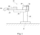
- Fig. 1 is a diagram illustrating a structure of the coater 10 in accordance with one implementation of the present invention
- Fig. 2 is a diagram illustrating a schematic structure of the coater 10.
- the coater 10 includes a coating robot 20, a paint supply unit 40 and a head unit 50.
- the coating robot 20 is mainly comprised of a base 21, a leg 22, a rotating shaft 23, a rotating arm 24, a first swivel arm 25, a second swivel arm 26, a wrist 27 and motors M1-M6 for driving the above parts.
- the base 21 is arranged on a mounting location, such as ground, but also can move relative to the mounting location.
- the leg 22 is set vertically upwards from the base 21.
- a joint may also be disposed between the leg 22 and the base 21 to allow the leg 22 to rotate relative to the base 21.
- an upper end of the leg 22 is provided with the rotating shaft 23. Further, the parts from the rotating shaft 23 to the wrist 27 correspond to a robot arm for moving the head unit 50.
- the rotating arm 24 is mounted on the rotating shaft 23 in such a manner that the rotating arm 24 can rotate freely via the shaft. It should be pointed out that the rotating arm 24 can be driven by the motor M1 to rotate and the motor M1 may be an electric motor or a pneumatic motor. Moreover, the motor M1 may be disposed within a housing of the rotating arm 24, or may be arranged within a housing of the rotating shaft 23. The motor M1, when being an electric one, is preferably disposed within the housing of the rotating shaft 23 or the rotating arm 24 and internal pressure of the housing is increased to avoid explosion (which is the same for the respective motors M2-M6).
- One end of the first swivel arm 25 is rotatably mounted on the rotating arm 24. Furthermore, the motor M2, which causes the first swivel arm 25 to rotate relative to the rotating shaft 23, may be received either within the housing of the rotating arm 24, or within the housing of the first swivel arm 25.
- One end of the second swivel arm 26 is mounted on a further end of the first swivel arm 25 in such a manner that the second swivel arm may swing freely via a shaft.
- the motor M3, which causes the second swivel arm 26 to rotate relative to the first swivel arm 25, may be received either within the housing of the first swivel arm 25, or within the housing of the second swivel arm 26.
- a further end of the second swivel arm 26 is provided with the wrist 27, which can rotate around a plurality of (e.g., three) shafts in different directions. Therefore, the direction of the nozzle head unit 50 can be controlled with high precision. Besides, the number of shafts can be any as long as it is more than two.
- Motors M4-M6 are provided to implement rotating movement of the above wrist 27 around each of the shafts.
- the motors M4-M6 may be received within the housing of the second swivel arm 26, or at other positions.
- the nozzle head unit 50 is mounted on the wrist 27 via a holder 30.
- the nozzle head unit 50 may be assembled to or disassembled from the wrist 27 freely via the holder 30.
- the above coater 10, including the rotating shaft 23, the rotating arm 24, the first swivel arm 25, the second swivel arm 26, the wrist 27 and the motors M1-M6 for driving the above parts, is a robot driven by 6 shafts.
- the coater 10 may be a robot driven by more than four shafts.
- a paint supply unit 40 is provided in the coater 10.
- the paint supply unit 40 supplies the paint for the nozzle head unit 50 and includes supply lines, pumps and valves for supplying the paint.
- a paint storage may be provided external to the coating robot 20 instead of being included therein.
- nozzle head unit 50 is illustrated next.
- the nozzle head unit 50 is mounted on the wrist 27 via the holder 30.
- Fig. 3 is a diagram illustrating a state of a nozzle spray surface 52 for spraying paint in the nozzle head unit 50 when viewed from the front.
- the nozzle spray surface 52 includes an individual nozzle head 53.
- the nozzle spray surface 52 also may be set as a head group comprised of a plurality of nozzle heads 53.
- the plurality of nozzle heads 53 for example, may be staggered as shown in Fig. 4 , but the configuration of the nozzle heads 53 in the head group also may be non-staggered.
- the nozzle head 53 is provided with a plurality of nozzles 54. Besides, a plurality of nozzle columns 55, in which the above nozzles 54 are connected along a specified direction, is provided on the nozzle head 53.
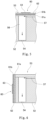
- Fig. 5 is a section view of a schematic structure of the nozzle head 53. As shown, a nozzle compression chamber 56 is arranged in the nozzle head 53 for each nozzle 54 and is connected to a paint supply path 57 used for supplying the paint. The nozzle compression chamber 56 is in communication with the nozzle 54 to spray the paint from each nozzle 54 by driving a piezoelectric substrate 60 described hereinafter to spray the paint.
- the piezoelectric substrate 60 is disposed at a top face (opposite to the nozzle 54) of the nozzle compression chamber 56.
- the piezoelectric substrate 60 includes two piezoelectric ceramic layers 61a and 61b as piezoelectrics, a common electrode 62 and an individual electrode 63.
- the piezoelectric ceramic layers 61a and 61b are scalable by applying voltage from the outside.
- the piezoelectric ceramic layers 61a and 61b may be made of ceramic materials like lead zirconate titanate (PZT) series, NaNbO3 series, BaTiO3 series, (BiNa) NbO3 series and BiNaNb5O15 series with strong dielectricity.
- PZT lead zirconate titanate
- the common electrode 62 is disposed between the piezoelectric ceramic layers 61a and 61b.
- a surface electrode (not shown) for use by the common electrode is formed on the upper surface of the piezoelectric substrate 60.
- the common electrode 62 and the surface electrode for use by the common electrode are electrically connected by a penetrating conductor (not shown) in the piezoelectric ceramic layer 61a.
- the individual electrode 63 is configured at a position opposite to the above nozzle compression chamber 56. A part of the piezoelectric ceramic layer 61a sandwiched by the common electrode 62 and the individual electrode 63 is polarized in a thickness direction.
- the piezoelectric ceramic layer 61a deforms due to piezoelectric effect.
- the piezoelectric ceramic layer 61b projects towards the nozzle compression chamber 56 to spray the paint.
- the common electrode 62 is not limited to the structure of being arranged at the top face of the nozzle compression chamber 56.
- a structure of being disposed at a side face of the nozzle compression chamber 56 illustrated in Fig. 6 also can be adopted.
- the piezoelectric substrate 60 of this implementation may change the applied driving voltage to vary the droplet size of the paint sprayed from the nozzle 54.
- the piezoelectric substrate 60 can generate at least two sizes of droplets through changing the driving voltage. Sometimes, there are for example 7 droplet sizes generated. But it is also possible that only one size or more than two sizes are generated.
- the piezoelectric substrate 60 corresponds to a nozzle driving mechanism.
- the nozzle driving mechanism also may correspond to components other than the piezoelectric substrate 60.
- a component driven for spraying the paint from the nozzle head 53 corresponds to the nozzle driving mechanism.
- a heater for heating the paint in the nozzle compression chamber 56 corresponds to the nozzle driving mechanism.
- a valve and a component driving the valve correspond to the nozzle driving mechanism.
- the control structure of the coater 10 is illustrated below with reference to Fig. 2 .
- the coater 10 includes an image processing unit 70, an arm control unit 80, a paint supply control unit 90, a head control unit 100 and a master control unit 110 and these components correspond to a coating control unit.
- the above components e.g., the paint supply control unit 90
- the coating control unit does not correspond to the coating control unit.
- various sensors which are omitted in the drawings are also included in the coater 10. Outputs from various sensors are input into some one of the arm control unit 80, the paint supply control unit 90, the head control unit 100 and the master control unit 110.
- the various sensors may include an accelerator sensor, an angular velocity sensor, a position detecting sensor for detecting positions of each drive part and an image sensor etc. Sensors except for the above listed ones also can be used.
- the image processing unit 70 in the above control structure handles image data processing based on the size of the coating object, such as vehicle or vehicle parts, when the nozzle head 51 is in a state of spraying the paint.
- the image processing unit 70 for example corresponds to the computer, which may be a part of the coater 10 or arranged separately from the coater 10.
- the image processing unit 70 is arranged separately from the coater 10
- data are received and transmitted via wired or wireless communications between the image processing unit 70 and the coater 10.
- the image processing unit 70 even if the image processing unit 70 is arranged separately from the coater 10, it may be included in the concept of the coater 10 or not.
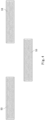
- the image processing unit 70 specifically produces image data D1 including a normal coating data region R1, an overlapping data region R2 and a non-spraying data region R3 as shown in Fig. 7 every time the nozzle head unit 50 scans the coating object (for each pass).
- image data D1 including a normal coating data region R1, an overlapping data region R2 and a non-spraying data region R3 as shown in Fig. 7 every time the nozzle head unit 50 scans the coating object (for each pass).
- two originally aligned image data D1 for a given pass P1 and its subsequent pass P2 are staggered for display to facilitate explanation.
- the normal coating data region R1 is a partial region of the image data D1 for performing a normal coating on the coating object.
- the overlapping data region R2 is a partial region of the image data D1 for performing the coating such that the attached parts of the paint between neighboring passes overlap.
- the non-spraying data region R3 is a partial region of the image data D1 outside of the end of the coating object without the need of being sprayed with paint.
- a pixel value of each pixel for example is set to 0, such that the nozzle 54 sprays the ink to obtain an expected film thickness.
- the pixel value 0 corresponds to spraying the paint in an expected film thickness.
- the maximum value obtained in the Grayscale also may correspond to spraying the paint in an expected film thickness.
- the maximum pixel value 8 of 8 Grayscale, the maximum pixel value 16 of 16 Grayscale and the maximum pixel value 256 of 256 Grayscale may correspond to spraying the paint in an expected film thickness.
- the maximum value or minimum value (0) in Grayscale for example also may correspond to spraying the paint in a thickness substantially greater than the expected film thickness.
- a desired pixel value (indicated as target pixel value below) between the maximum pixel value and the minimum pixel value of each pixel is defined as coating with an expected film thickness. Therefore, even if performed with the target pixel value, the coating also may be executed at the side of the nozzle head unit 50 with surplus capacity. Accordingly, for example, in accordance with the market where the vehicle is manufactured and sold, it is easy to perform the coating which is set to an appropriate thickness.
- the nozzle columns 55 in the nozzle spray surface 52 are tilted with respect to the scanning direction (pass direction). Therefore, in the image processing unit 70, the respective nozzles 54 preferably spray the paint after reaching a spray starting position of the coating object and the normal coating data region R1 and the overlapping data region R2 are shifted in the scanning direction for each of the nozzles 54, so as to produce the image data D1.
- the pixel values of the respective pixels are set to specified intermediate value in the overlapping data region R2 by the image processing unit 70.
- the two image data D1 of the adjacent passes include an overlapping data region (one-end overlapping data region) R21 and a further overlapping data region (other-end overlapping data region) R22 which overlap with each other
- a pixel value corresponding to about half of the coating film thickness to be formed sometimes is set in the overlapping data region R21 and a pixel value corresponding to about half of the coating film thickness to be formed is also set in the further overlapping data region R22.
- the one-end overlapping data region R21 in the previous pass and the other-end overlapping data region R22 in the subsequent pass overlap with each other.
- the pixel value of the one-end overlapping data region R21 and the pixel value of the other-end overlapping data region R22 are respectively set, such that the coating film of the one-end overlapping data region R21 in the previous pass is formed thicker than that of the other-end overlapping data region R22 in the subsequent pass in one example not encompassed by the wording of the claims but useful for understanding embodiments described herein.
- the pixel value of the one-end overlapping data region R21 and the pixel value of the other-end overlapping data region R22 are respectively set, such that the coating film of the one-end overlapping data region R21 in the previous pass is formed thinner than that of the other-end overlapping data region R22 in the subsequent pass in one example not encompassed by the wording of the claims but useful for understanding embodiments described herein.
- a pixel value (such as maximum pixel value) corresponding to not spraying the paint is set in the non-spraying data region R3.
- the size of the image data D1 in the pass direction (operation direction) is preferably produced to minimize the area of the non-spraying data region R3 as much as possible.
- the image data D1 at a position like an end side of the vehicle, only include either the one-end overlapping data region R21 or the other-end overlapping data region R22.
- the arm control unit 80 is provided for controlling the driving of the above motors M1-M6.
- the arm control unit 80 includes a memory 81 which stores programs and data produced via robot teaching. Besides, in the arm control unit 80, the driving of the motors M1-M6 is controlled based on the programs and data stored in the memory 81 and the image processing in the image processing unit 70. Because of the above control, the nozzle head unit 50 can go through an expected position for executing the coating at a desired speed and stop at a specified position.
- the memory 81 also may be arranged inside the coater 10 or external to the coater 10 to receive and transmit the information via wired or wireless communications.
- the paint supply control unit 90 controls paint supply to the nozzle head unit 50 and specifically controls operation of the pumps and values included in the paint supply unit 40. At this time, the paint supply control unit 90 controls the operation of the above pumps and values preferably by supplying the paint at a constant pressure (quantitative approach as an example) to the nozzle head unit 50. Besides, a head control unit 100 controls the operation of the piezoelectric substrate 60 in the nozzle head unit 50 based on the image processing of the image processing unit 70.
- the master control unit 100 transmits specified control signals to the above arm control unit 80, paint supply control unit 90 and head control unit 100 in such a way that the above motors M1-M6, the paint supply unit 40 and the piezoelectric substrate 60 cooperate to coat the coating object.
- the image data D1 is produced on the basis of the measured sizes of the coating object, wherein the image data D1 is produced respectively for each pass of the scanning of the nozzle head unit 50.
- the produced image data D1 includes the normal coating data region Rl, the overlapping data region R2 and the non-spraying data region R3 as mentioned above.
- the master control unit 110 sends, based on the image data D1 produced by the image processing unit 70, control signals to the arm control unit 80, the paint supply control unit 90 and the head control unit 100 for executing the coating.
- the arm control unit 80 enables at least one of the motors M1-M6 to drive at a specified speed, so as to coat the coating object.
- the paint supply control unit 90 detects, via the sensors not shown, that the nozzle head unit 50 reaches a specified position relative to the coating object, a given nozzle 54 of the nozzle head unit 50 starts to spray the paint.
- the head control unit 100 controls driving of the piezoelectric substrate 60 of the respective nozzles 54 by allowing the nozzles to sequentially spray the paint starting from the nozzle 54 arriving at the end of the coating object. Therefore, a coating surface C is formed on the coating object as shown in Fig. 8 .
- This coating surface C is formed by scanning a plurality of segmented coating surfaces CD coated in each scanning (pass) and overlapping parts of the adjacent segmented coating surfaces CD.
- a normal coating region CR1 is formed by spraying the paint corresponding to the normal coating data region R1 and an overlapping coating region CR2 is formed by spraying the paint corresponding to the overlapping data region R2.
- an one-end overlapping coating region CR21 of the segmented coating surface CD corresponding to the one-end overlapping region R21 and an other-end overlapping coating region CR22 of the segmented coating surface CD corresponding to the other-end overlapping coating region R22 in the previous pass P1 are mixed.
- the one-end overlapping coating region CR21 may overlap the overlapping coating region CR2.
- the overlapping coating region CR2 is in a state of spraying less paint than the normal coating region CR1.
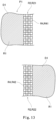
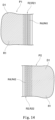
- Fig. 9 is a section view of an overlapping state between the one-end overlapping coating region CR21 and the other-end overlapping coating region CR22.
- an average thickness of the normal coating region CR1 is set to T1 in the previous pass P1 and the subsequent pass P2.
- a total thickness T4 of a thickness T2 of the one-end overlapping coating region CR21 and a thickness T3 of the other-end overlapping coating region CR22 overlapping with the one-end overlapping coating region CR21 is set to be equal to or substantially equal to the thickness T1.
- the subdivided coating regions are adjoined in embodiments described herein, which also corresponds to mixing.
- the thickness of the coating film of the respective subdivided coating regions is also equal to the above T1.
- the head control unit 100 controls the paint spray according to the third coating control based on the image data D1.
- the first coating control and the second coating control are mere examples useful for understanding the invention but are not encompassed by the wording of the claims.
- the first coating control is performed in such a way that droplet size of the paint sprayed from the nozzle 54 in the one-end overlapping coating region CR21 and the other-end overlapping coating region CR22 is smaller than that in the normal coating region CR1.
- the painting is executed in such a way that a sum of a volume of small-sized droplets sprayed in the one-end overlapping coating region CR21 and a volume of small-sized droplets sprayed in the other-end overlapping coating region CR22 equals to a volume of large-sized droplets sprayed in the normal coating region CR1.
- the volume of a sphere usually is in direct proportion to the cube of the radius and the surface area of the sphere is directly proportional to the square of the radius. Therefore, as the radius becomes smaller, some components (organic solvent etc.) included in the paint droplet tend to disperse outwards. Furthermore, of solidified components constituting the coating film in the paint excluding the organic solvent, the total volume of the solidified components in the one-end overlapping coating region CR21 and the other-end overlapping coating region CR22 should be equal to the volume of the solidified components in the normal coating region CR1.
- a radius E1 of the droplet sprayed in the one-end overlapping coating region CR21 is greater than a radius E2 of the droplet sprayed in the other-end overlapping coating region CR22.
- the image data D1 of each pass also may be produced in the image processing unit 70 by arranging the one-end overlapping data region R21 corresponding to the radius E1 of the droplet in the previous pass P1 and arranging the other-end overlapping coating region CR22 corresponding to the radius E2 of the droplet in the subsequent pass P2.
- the image data D1 of each pass are half-toned in the image processing unit 70 or the head control unit 100.
- the halftone processing may be performed by dithering or error diffusion.
- error diffusion, dithering and concentration patterning also can be used in the halftone processing.
- Fig. 10 is a diagram illustrating an example of the halftone processing in the overlapping data region R2. It should be pointed out that various numbers in the matrix of Fig. 10 represent the size of the paint droplet (dot) and the dot size gets bigger as the number increases.
- a dot of a third size sorted in a descending order in an interested pixel is set to ON
- a dot of a sixth size in a pixel adjacent to the interested pixel on the left is set to ON
- a dot of a second size in a pixel to the left diagonal of the interested pixel is set to ON
- a dot in a pixel above the interested pixel is set to OFF (0) as shown in Fig. 10 , and so on.
- the dot size is determined for each pixel.
- the piezoelectric substrate 60 is driven, based on the image processing, to spray droplets from the nozzle 54 relative to the coating object. Therefore, the coating is performed with dot sizes dispersed especially in the overlapping data region R2. After the paint is applied to the coating object, the paint flows to the surroundings to form a coating film of the specified thickness.
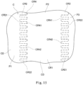
- the dot size preferably is the maximum size or a value approximate to the maximum size in the normal coating data region R1 as shown in Fig. 11 .
- the image processing is performed preferably by arranging large-sized dots next to or around the small-sized dots.
- the normal coating region CR1 based on the normal coating data region R1 can form a coating film of the above thickness T1.
- the one-end overlapping coating region CR21 based on the one-end overlapping data region R21 can form a coating film of the above thickness T2
- the other-end overlapping coating region CR22 based on the other-end overlapping data region R22 can form a coating film of the above thickness T3.
- the droplets (dots) of the paint sprayed from the nozzle 54 are set to the same size in the second coating control to form the coating film.
- the expected film thickness is achieved by changing the number of dots sprayed into a certain region.
- the number of dots sprayed from the nozzle 54 per unit area is changed by varying the frequency for driving the piezoelectric substrate 60.
- the droplet (dot) size has 7 levels
- the dot of a given size is sprayed to form the normal coating region CR1 and the overlapping coating region CR2.
- the droplets (dots) of the third level or the fourth level size may be sprayed for reducing the coating time and lowering complexity of the coating control.
- the number of dots sprayed per unit area of the coating object in the normal coating region CR1 on the basis of the normal coating data region R1 is set to D1.
- the number of dots sprayed per unit area of the coating object in the overlapping data region R2 is set to D2.
- the normal coating region CR1 and the overlapping coating region CR2 are respectively formed by setting D1>D2.
- the number of dots sprayed per unit area of the coating object in the one-end overlapping coating region CR21 is set to D21 while the number of dots sprayed per unit area of the coating object in the in the other-end overlapping coating region CR22 is set to D22.
- the thickness T2 of the coating film in the overlapping coating region CR21 and the thickness T3 of the coating film in the other-end overlapping coating region CR22 also may be smaller than the thickness T1 of the coating film in the normal coating region CR1. Accordingly, when the overlapping coating region CR21 overlaps the other-end overlapping coating region CR22, the coating film of a thickness identical to the thickness T1 in the normal coating region CR1 also can be formed in a three dimensional way.
- the area of the overlapping data region R2 (overlapping coating region CR2) is expanded in the third coating control according to embodiments described herein.
- a data region R4 for subdivision shown in Figs. 12-14 is produced by expanding the area.
- a data region R41 for one-end subdivision is produced in one-end overlapping data region R21 of the previous pass P1 while a data region R42 for other-end subdivision is produced in the other-end overlapping coating region CR22 of the subsequent pass P2.
- the overlapping coating region CR2 of the uniform thickness can be formed by combining the data region R41 for one-end subdivision with the data region R42 for other-end subdivision.
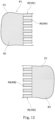
- Fig. 12 a diagram illustrating a state where the data region R41 for one-end subdivision and the data region R42 for other-end subdivision are provided in a comb like shape.
- the coating is executed based on the image data D1 shown in Fig. 12 , it changes to the state shown in Fig. 15 .
- the coating part corresponding to the data region R41 for one-end subdivision is an one-end subdivided coating region R41 and the coating part corresponding to the data region R42 for other-end subdivision is an other-end subdivided coating region CR42.
- the one-end subdivided coating region R41 and the other-end subdivided coating region CR42 are adjoined, rather than overlapping with each other in the thickness direction. Therefore, the one-end subdivided coating region CR41 and the other-end subdivided coating region CR42 are engaged with each other in a comb-like shape.
- Fig. 13 is a diagram illustrating a state where the data region R41 for one-end subdivision and the data region R42 for other-end subdivision are provided in a mesh shape.
- the coating is executed based on the image data D1 in Fig. 13 , it changes to the state shown by Fig. 16 , in which the one-end subdivided coating region CR41 and the other-end subdivided coating region CR42 are configured in a checkered pattern, rather than overlapping with each other.
- Fig. 14 is a diagram illustrating a state where the data region R41 for one-end subdivision and the data region R42 for other-end subdivision are provided in a gradation form.
- the coating is executed based on the image data D1 in Fig. 14 , it changes to the state shown by Fig. 17 , in which the one-end subdivided coating region CR41 and the other-end subdivided coating region CR42 respectively change to gradation patterns without overlapping with each other.
- the coating is performed on the coating object based on the image data D1 in which the data region R4 for subdivision exists in the overlapping data region R2, the respective subdivided coating regions CR4 have the thickness of T1. Therefore, the coating is performed with a uniform thickness of T1 in the overlapping coating region CR2.
- the coating object is coated integrally by repeatedly scanning the nozzle head unit 50 with any one of the first coating control, the second coating control and the third coating control or combinations thereof and simultaneously spraying the paint from the nozzle 54 during the scanning.
- the coating control unit controls the execution of the coating on the coating object by repeating scanning of the nozzle head unit for a plurality of times in a state of being divided into segmented coating surfaces CD formed by each scanning of the nozzle head unit50.
- the coating control unit performs the coating by forming a normal coating region CR1 and an overlapping coating region CR2 in the segmented coating surfaces CD, wherein the coating is performed in the normal coating region CR1 so as to have a target coating film thickness Tl, and the coating is performed in the overlapping coating region CR2 in a state where a spray amount of the paint is reduced compared to the normal coating region CR1.
- the coating control unit mixes the overlapping coating region CR2 in the segmented coating surface CD to be coated in the next scan with the overlapping coating region CR2 in the segmented coating surface CD coated in the previous scan and takes the coating film thickness of the mixed overlapping coating region CR2 as the target coating film thickness to perform the coating.
- the thickness of the coating film in the overlapping coating region CR2 where the coating position (segmented coating surface CD) in the previous scan is mixed with the coating position (segmented coating surface CD) in the next scan can be set identical to the thickness of the normal coating region CR1.
- the coating over the entire coating surface C thus can be highly smoothed, which can prevent the bulge induced by the coating position (segmented coating surface CD) in the previous scan overlapping with the coating position (segmented coating surface CD) in the next scan from damaging smoothness.
- the driving of the piezoelectric substrate 60 (nozzle driving mechanism) and of the motors M1-M6 (arm driving mechanism) may also be controlled, to allow the overlapping coating region CR2 of the segmented coating surface CD to be coated in the next scan to overlap the overlapping coating region CR2 of the segmented coating surface CD coated in the previous scan in the thickness direction, thereby coating the target with coating film thickness.
- this position is also coated to serve as the target coating film thickness T1, thereby coating the entire coating surface C at a high level of smoothness.
- the driving of the piezoelectric substrate 60 may also be controlled, such that the paint sprayed from the nozzle 54 in the overlapping coating region CR2 has a smaller droplet size than the paint sprayed in the normal coating region CR1.
- the droplet of the paint sprayed from the nozzle 54 may be optimized to the minimum size, even if the overlapping coating regions CR2 in the previous and next scans overlap, this position is also coated to serve as the target coating film thickness T1, thereby coating the entire coating surface C at a high level of smoothness.
- the driving of the nozzle driving mechanism may also be controlled, such that the number of droplets of the paint sprayed per unit area of the coating object in the overlapping coating region CR2 is less than that in the normal coating region CR1.
- the number of droplets (dots) sprayed from the nozzle 54 may be adjusted to an optimal number less than the normal coating region CR1, even if the overlapping coating regions CR2 in the previous and next scans overlap, this position is also coated to serve as the target coating film thickness T1, thereby coating the entire coating surface C at a high level of smoothness.
- the thickness of the coating film can be calculated proportionally and therefore be easily controlled.
- the coating is controlled by arranging a plurality of subdivided coating regions CR4 in the overlapping coating region CR2 and by placing the subdivided coating region CR4 in the overlapping coating region CR2 formed in the previous scan adjacent to the subdivided coating region CR4 in the overlapping coating region CR2 formed in the next scan.
- the subdivided coating region CR4 formed in the previous scan and the subdivided coating region CR4 formed in the next scan are adjoined, rather than overlapping with each other. Therefore, the amount of paint sprayed from the nozzle 54 is adjusted to perform the coating with the coating film thickness T1 as the target in the overlapping coating region CR2, thereby coating the entire coating surface C at a high level of smoothness.
- the thickness T2 of the one-end overlapping coating region CR21 for example has a substantially the same thickness in its width direction and the thickness T3 of the other-end overlapping coating region CR22 also has a substantially the same thickness in its width direction.
- the thickness of the one-end overlapping coating region CR21 and the other-end overlapping coating region CR22 may also be non-uniform.
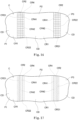
- the coating is performed in such a way that the thickness gradually decreases with an increase of distance from the normal coating region CR1 in the one-end overlapping coating region CR21 of the previous pass P1 as shown in Fig. 18 .
- the coating is also performed in such a way that the thickness gradually decreases with an increase of distance from the normal coating region CR1 in the other-end overlapping coating region CR22 of the subsequent pass P2.
- the coating is executed for example using the method of changing dot size in the above first coating control, wherein the dot size decreases with an increase of distance from the respective normal coating regions CR1.
- the coating is executed using the method of changing the number of droplets (dots) sprayed per unit area in the above second coating control, wherein the number of droplets (dots) sprayed decreases with an increase of distance from the respective normal coating regions CR1.
- the coating is performed in such a way that the thickness decreases periodically with an increase of distance from the normal coating region CR1 in the one-end overlapping coating region CR21 of the previous pass P1 as shown in Fig. 19 .
- the coating is also performed in such a way that the thickness decreases periodically with an increase of distance from the normal coating region CR1 in the other-end overlapping coating region CR22 of the subsequent pass P2.
- the periodical change of the thickness in Fig. 19 also can be implemented using the method of changing dot size in the above first coating control and/or the method of changing the number of droplets (dots) in the second coating control as depicted in the above with reference to Fig. 18 .
- the above implementation also explains the case of forming the coating film of constant thickness.
- the coater 10 and the coating method of the present invention are not limited to forming the coating film of constant thickness.
- the coater 10 and the coating method of the present invention are also applicable.
- the thickness of the coating film as depicted sometimes changes according to the coating position. Even in this case, there is a target coating film thickness for each position. Therefore, the overlapping coating region in the segmented coating surface to be coated in the next scan is mixed with the overlapping coating region in the segmented coating surface coated in the previous scan. The coating film thickness of the mixed overlapping coating region can act as the target coating film thickness to coat each position.
- the third coating control is explained for the overlapping coating region and examples useful for understanding are given in the first coating control and the second coating control.
- at least two of the first, second and third coating control also may be combined for execution.
- the coating may be executed by changing the dot size like the first coating control and changing the number of dots sprayed per unit area like the second coating control simultaneously.
- the coating may also be executed by changing the dot size like the first coating control and forming the subdivided coating region like the third coating control simultaneously.
- the coating may also be executed by changing the number of dots sprayed per unit area like the second coating control and forming the subdivided coating region like the third coating control simultaneously.
Landscapes
- Engineering & Computer Science (AREA)
- Robotics (AREA)
- Mechanical Engineering (AREA)
- Manufacturing & Machinery (AREA)
- Spray Control Apparatus (AREA)
- Coating Apparatus (AREA)
- Application Of Or Painting With Fluid Materials (AREA)
- Ink Jet (AREA)
Claims (11)
- Dispositif de revêtement (10) pour revêtir un objet de revêtement en pulvérisant de la peinture à partir d'une buse à la manière d'un jet d'encre, le dispositif de revêtement comprenant :une unité de tête de buse (50) comportant une tête de buse (53) formée avec une pluralité de buses (54) au niveau d'une surface de pulvérisation de buse (52) et un mécanisme d'entraînement de buse (60) provoquant la pulvérisation de la peinture à partir des buses ;un bras de robot (20) comportant une pluralité de bras (24, 25, 26) susceptibles de tourner relativement par l'intermédiaire de tiges et d'un mécanisme d'entraînement de bras (M1 à M6) pour déplacer les bras, et conçu pour déplacer l'unité de tête de buse (50) dans un état de maintien de l'unité de tête de buse (50) par l'intermédiaire de l'entraînement du mécanisme d'entraînement de bras (M1 à M6) ; etune unité de commande de revêtement (70 ; 80 ; 90 ; 100 ; 110) conçue pour commander l'entraînement du mécanisme d'entraînement de buse (60) et l'entraînement du mécanisme d'entraînement de bras (M1 à M6) pour exécuter le revêtement sur l'objet de revêtement ;dans lequel l'unité de commande de revêtement (70 ; 80 ; 90 ; 100 ; 110) commande l'exécution du revêtement sur l'objet de revêtement en répétant le balayage de l'unité de tête de buse (50) une pluralité de fois dans un état de division en surfaces de revêtement segmenté (CD) formées par chaque balayage de l'unité de tête de buse (50) ; etdans lequel l'unité de commande de revêtement (70 ; 80 ; 90 ; 100 ; 110) effectue le revêtement en formant une région de revêtement normal (CR1) et une région de revêtement en chevauchement (CR2 ; CR21 ; CR22) dans les surfaces de revêtement segmenté, dans lequel le revêtement est effectué dans la région de revêtement normal (CR1) de sorte à avoir une épaisseur de film de revêtement cible, et le revêtement est effectué dans la région de revêtement en chevauchement (CR2 ; CR21 ; CR22) dans un état où une quantité de pulvérisation de la peinture est réduite comparativement à la région de revêtement normal (CR1) ;dans lequel l'unité de commande de revêtement (70 ; 80 ; 90 ; 100 ; 110) effectue une commande de revêtement en chevauchement en mélangeant la région de revêtement en chevauchement dans la surface de revêtement segmenté (CD) à revêtir dans un balayage suivant avec la région de revêtement en chevauchement (CR2 ; CR21 ; CR22) dans la surface de revêtement segmenté (CD) revêtue dans un balayage précédent et en prenant l'épaisseur de film de revêtement de la région de revêtement en chevauchement mixte (CR2 ; CR21 ; CR22) en tant qu'épaisseur de film de revêtement cible (T1) pour effectuer le revêtement ; etdans lequel, dans la commande de revêtement en chevauchement, le revêtement est commandé en agençant une pluralité de régions de revêtement subdivisé (CR4 ; CR41; CR42) dans la région de revêtement en chevauchement (CR2 ; CR21 ; CR22) et en plaçant les régions de revêtement subdivisé (CR4 ; CR41 ; CR42) dans la région de revêtement en chevauchement formée dans le balayage précédent de manière adjacente aux régions de revêtement subdivisé (CR4 ; CR41 ; CR42) dans la région de revêtement en chevauchement (CR2 ; CR21 ; CR22) formée dans le balayage suivant.
- Dispositif de revêtement selon la revendication 1, dans lequel
la pluralité de régions de revêtement subdivisé (CR4 ; CR41; CR42) dans la région de revêtement en chevauchement (CR2 ; CR21 ; CR22) comprend une région de revêtement subdivisé d'une extrémité (CR41) et une région de revêtement subdivisé de l'autre extrémité (CR42) en prise l'une avec l'autre à la façon d'un peigne. - Dispositif de revêtement selon la revendication 1, dans lequel
la pluralité de régions de revêtement subdivisé (CR4 ; CR41; CR42) dans la région de revêtement en chevauchement (CR2 ; CR21 ; CR22) comprend une région de revêtement subdivisé d'une extrémité (CR41) et une région de revêtement subdivisé de l'autre extrémité (CR42) fournies dans un motif en damier. - Dispositif de revêtement selon la revendication 1, dans lequel
la pluralité de régions de revêtement subdivisé (CR4 ; CR41; CR42) dans la région de revêtement en chevauchement (CR2 ; CR21 ; CR22) comprend une région de revêtement subdivisé d'une extrémité (CR41) et une région de revêtement subdivisé de l'autre extrémité (CR42) fournies en forme de gradation. - Procédé de revêtement pour revêtir un objet de revêtement en pulvérisant de la peinture à partir d'une buse (54) à la manière d'un jet d'encre, le procédé de revêtement comprenant :une unité de tête de buse (50) comportant une tête de buse (53) formée avec une pluralité de buses (54) au niveau d'une surface de pulvérisation de buse et un mécanisme d'entraînement de buse (60) provoquant la pulvérisation de la peinture à partir des buses (54) ;un bras de robot (20) comportant une pluralité de bras (24 ; 25 ; 26) susceptibles de tourner relativement par l'intermédiaire de tiges et d'un mécanisme d'entraînement de bras (M1 à M6) pour déplacer les bras, et conçu pour déplacer l'unité de tête de buse (50) dans un état de maintien de l'unité de tête de buse (50) par l'intermédiaire de l'entraînement du mécanisme d'entraînement de bras (M1 à M6) ; etune unité de commande de revêtement (70 ; 80 ; 90 ; 100 ; 110) conçue pour commander l'entraînement du mécanisme d'entraînement de buse (60) et l'entraînement du mécanisme d'entraînement de bras (M1 à M6) pour exécuter le revêtement sur l'objet de revêtement,dans lequel le procédé de revêtement sur la base de la commande de l'unité de commande de revêtement (70 ; 80 ; 90 ; 100 ; 110) comprend :une étape de balayage dans laquelle l'unité de tête de buse (50) est amenée à balayer de manière répétée une pluralité de fois par rapport à l'objet de revêtement ; etune étape de revêtement segmenté dans laquelle des surfaces de revêtement segmenté (CD) sont formées en pulvérisant la peinture à partir de la buse (54) par rapport à l'objet de revêtement pendant chaque étape de balayage ; etles surfaces de revêtement segmenté (CD) comprennent une région de revêtement normal (CR1) revêtue d'une épaisseur de film de revêtement cible (T1) et une région de revêtement en chevauchement (CR2 ; CR21; CR22) revêtue d'une quantité de pulvérisation de la peinture inférieure à celle de la région de revêtement normal (CR1) ;la peinture est pulvérisée à partir des buses (54) de telle sorte que la région de revêtement en chevauchement (CR2 ; CR21 ; CR22) dans la surface de revêtement segmenté (CD) à revêtir dans une étape de revêtement segmenté suivante est mélangée avec la région de revêtement en chevauchement (CR2 ; CR21 ; CR22) dans la surface de revêtement segmenté (CD) revêtue dans une étape de revêtement segmenté précédente et l'épaisseur de film de revêtement de la région de revêtement en chevauchement mixte devient l'épaisseur de film de revêtement cible (T1) ; etdans lequel, dans l'étape de revêtement segmenté, le revêtement est commandé par l'agencement d'une pluralité de régions de revêtement subdivisé (CR4 ; CR41; CR42) dans la région de revêtement en chevauchement (CR2 ; CR21 ; CR22) et par le placement des régions de revêtement subdivisé (CR4 ; CR41 ; CR42) dans la région de revêtement en chevauchement formée dans le balayage précédent de manière adjacente aux régions de revêtement subdivisé (CR4 ; CR41 ; CR42) dans la région de revêtement en chevauchement (CR2 ; CR21 ; CR22) formée dans le balayage suivant.
- Procédé de revêtement selon la revendication 5, dans lequel
la pluralité de régions de revêtement subdivisé (CR4 ; CR41; CR42) dans la région de revêtement en chevauchement (CR2 ; CR21 ; CR22) comprend une région de revêtement subdivisé d'une extrémité (CR41) et une région de revêtement subdivisé d'une autre extrémité (CR42), et dans lequel, dans l'étape de revêtement segmenté, la région de revêtement subdivisé d'une extrémité (CR41) et la région de revêtement subdivisé d'une autre extrémité (CR42) sont en prise l'une avec l'autre à la façon d'un peigne. - Procédé de revêtement selon la revendication 5, dans lequel
la pluralité de régions de revêtement subdivisé (CR4 ; CR41; CR42) dans la région de revêtement en chevauchement (CR2 ; CR21 ; CR22) comprend une région de revêtement subdivisé d'une extrémité (CR41) et une région de revêtement subdivisé de l'autre extrémité (CR42), et dans lequel, dans l'étape de revêtement segmenté, la région de revêtement subdivisé d'une extrémité (CR41) et la région de revêtement subdivisé de l'autre extrémité (CR42) sont fournies dans un motif en damier. - Procédé de revêtement selon la revendication 5, dans lequel
la pluralité de régions de revêtement subdivisé (CR4 ; CR41; CR42) dans la région de revêtement en chevauchement (CR2 ; CR21 ; CR22) comprend une région de revêtement subdivisé d'une extrémité (CR41) et une région de revêtement subdivisé de l'autre extrémité (CR42), et dans lequel, dans l'étape de revêtement segmenté, la région de revêtement subdivisé d'une extrémité (CR41) et la région de revêtement subdivisé de l'autre extrémité (CR42) sont fournies en forme de gradation. - Procédé de revêtement selon l'une quelconque des revendications 5 à 8, dans lequella pluralité de régions de revêtement subdivisé (CR4 ; CR41; CR42) dans la région de revêtement en chevauchement (CR2 ; CR21 ; CR22) comprend une région de revêtement subdivisé d'une extrémité (CR41) et une région de revêtement subdivisé de l'autre extrémité (CR42), et dans lequelune région de données (R41) pour la région de revêtement subdivisé d'une extrémité (CR41) est produite dans une région de données de chevauchement d'une extrémité (R21) du balayage précédent et une région de données (R42) pour la région de revêtement subdivisé de l'autre extrémité (CR42) est produite dans la région de revêtement en chevauchement de l'autre extrémité (CR22) du balayage suivant.
- Procédé selon la revendication 9, dans lequel la région de données (R41) pour la région de revêtement subdivisé d'une extrémité (CR41) et la région de données (R42) pour la région de revêtement subdivisé de l'autre extrémité (CR42) sont fournies sous au moins une forme parmi une forme de peigne, une forme de maille et une forme de gradation.
- Procédé de revêtement selon la revendication 5, dans lequel
dans l'étape de revêtement segmenté, la peinture est pulvérisée à partir des buses (54) de telle sorte que le nombre de gouttelettes de la peinture pulvérisée par unité de surface de l'objet de revêtement dans la région de revêtement en chevauchement (CR2 ; CR21 ; CR22) soit inférieur à celui dans la région de revêtement normal (CR1).
Applications Claiming Priority (1)
| Application Number | Priority Date | Filing Date | Title |
|---|---|---|---|
| PCT/JP2019/025448 WO2020261443A1 (fr) | 2019-06-26 | 2019-06-26 | Dispositif d'enduction et procédé d'enduction |
Publications (3)
| Publication Number | Publication Date |
|---|---|
| EP3789123A1 EP3789123A1 (fr) | 2021-03-10 |
| EP3789123A4 EP3789123A4 (fr) | 2021-04-28 |
| EP3789123B1 true EP3789123B1 (fr) | 2023-04-26 |
Family
ID=74044365
Family Applications (1)
| Application Number | Title | Priority Date | Filing Date |
|---|---|---|---|
| EP19850781.6A Active EP3789123B1 (fr) | 2019-06-26 | 2019-06-26 | Dispositif d'enduction et procédé d'enduction |
Country Status (5)
| Country | Link |
|---|---|
| US (1) | US11491788B2 (fr) |
| EP (1) | EP3789123B1 (fr) |
| JP (1) | JP7285827B2 (fr) |
| CN (2) | CN112437698A (fr) |
| WO (1) | WO2020261443A1 (fr) |
Families Citing this family (12)
| Publication number | Priority date | Publication date | Assignee | Title |
|---|---|---|---|---|
| JP7342727B2 (ja) * | 2020-02-06 | 2023-09-12 | トヨタ車体株式会社 | 塗装装置、塗装方法及びプログラム |
| US11826768B2 (en) * | 2021-03-11 | 2023-11-28 | Ford Global Technologies, Llc | Method and apparatus for adaptive control and real-time edge tracking of adhesive and sealer dispensing |
| JP6948482B1 (ja) * | 2021-03-25 | 2021-10-13 | アーベーベー・シュバイツ・アーゲーABB Schweiz AG | 塗装ロボットシステムおよび塗装方法 |
| JP7676917B2 (ja) * | 2021-04-30 | 2025-05-15 | セイコーエプソン株式会社 | 立体物印刷装置、および、立体物印刷方法 |
| US20240391248A1 (en) * | 2021-09-16 | 2024-11-28 | Abb Schweiz Ag | Method Of Applying Coating Medium, Coated Object, Control System And Coating System |
| JP7066035B1 (ja) | 2021-11-04 | 2022-05-12 | アーベーベー・シュバイツ・アーゲー | 塗装ロボット |
| JP7809978B2 (ja) * | 2021-12-24 | 2026-02-03 | 株式会社リコー | 液体吐出装置、液体吐出方法、プログラム、および液体吐出システム |
| CN117943265A (zh) * | 2022-10-20 | 2024-04-30 | 青岛海尔智慧电器设备有限公司 | 热水器内胆喷涂方法及生产线 |
| JP2024115319A (ja) * | 2023-02-14 | 2024-08-26 | セイコーエプソン株式会社 | 立体物印刷装置 |
| JP7527452B1 (ja) | 2023-10-10 | 2024-08-02 | アーベーベー・シュバイツ・アーゲー | 塗装ロボットおよび塗装方法 |
| WO2025134361A1 (fr) * | 2023-12-22 | 2025-06-26 | 日産自動車株式会社 | Système de revêtement et procédé de production d'automobile |
| CN119426038B (zh) * | 2024-12-23 | 2025-11-21 | 中建八局新型建造工程有限公司 | 智能调节多面喷涂机 |
Family Cites Families (29)
| Publication number | Priority date | Publication date | Assignee | Title |
|---|---|---|---|---|
| JP4231564B2 (ja) | 1997-10-23 | 2009-03-04 | オリンパス株式会社 | オンディマンドコーティング装置 |
| JPH11245384A (ja) * | 1998-02-27 | 1999-09-14 | Canon Inc | 記録装置および記録方法 |
| JP3988645B2 (ja) * | 2002-03-06 | 2007-10-10 | セイコーエプソン株式会社 | 吐出方法、吐出装置、カラーフィルタの製造方法、エレクトロルミネッセンス装置の製造方法、およびプラズマディスプレイパネルの製造方法 |
| JP4003743B2 (ja) | 2003-12-11 | 2007-11-07 | ブラザー工業株式会社 | インクジェットプリンタ |
| DE602005023445D1 (de) * | 2004-06-01 | 2010-10-21 | Abb Kk | Malverfahren |
| JP4159525B2 (ja) | 2004-08-23 | 2008-10-01 | 株式会社石井表記 | 配向膜形成方法およびインクジェット式プリントヘッド噴出検査装置 |
| JP4564454B2 (ja) * | 2006-01-19 | 2010-10-20 | 東京エレクトロン株式会社 | 塗布方法及び塗布装置及び塗布処理プログラム |
| JP4389953B2 (ja) * | 2007-03-22 | 2009-12-24 | セイコーエプソン株式会社 | パターン形成方法 |
| DE102008053178A1 (de) | 2008-10-24 | 2010-05-12 | Dürr Systems GmbH | Beschichtungseinrichtung und zugehöriges Beschichtungsverfahren |
| EP2199434A1 (fr) * | 2008-12-19 | 2010-06-23 | FEI Company | Procédé de formation de structures microscopiques sur un substrat |
| DE102009004878A1 (de) * | 2009-01-16 | 2010-07-29 | Bauer, Jörg R. | Verfahren zum Beschichten, insbesondere Lackieren, einer Oberfläche sowie digitales Beschichtungssystem |
| DE102010019612A1 (de) * | 2010-05-06 | 2011-11-10 | Dürr Systems GmbH | Beschichtungseinrichtung, insbesondere mit einem Applikationsgerät, und zugehöriges Beschichtungsverfahren, das einen zertropfenden Beschichtungsmittelstrahl ausgibt |
| JP5688268B2 (ja) * | 2010-11-08 | 2015-03-25 | 株式会社エルエーシー | 曲面塗装装置 |
| JP5730698B2 (ja) * | 2011-07-15 | 2015-06-10 | 株式会社ミマキエンジニアリング | 印刷方法および印刷装置 |
| JP6198499B2 (ja) * | 2013-07-04 | 2017-09-20 | 株式会社エルエーシー | プリント装置 |
| JP6085578B2 (ja) * | 2014-03-11 | 2017-02-22 | 住友重機械工業株式会社 | 膜形成方法及び膜形成装置 |
| CN111350090B (zh) * | 2015-05-27 | 2022-09-23 | 耐克创新有限合伙公司 | 基于颜色密度的厚度补偿印刷 |
| US9452616B1 (en) * | 2015-05-29 | 2016-09-27 | The Boeing Company | System and method for printing an image on a surface |
| CN108141938B (zh) * | 2015-09-30 | 2020-02-14 | 住友化学株式会社 | 薄膜制造方法及有机el器件的制造方法 |
| JP6695029B2 (ja) * | 2015-12-28 | 2020-05-20 | パナソニックIpマネジメント株式会社 | インク塗布装置とインク塗布方法 |
| FR3048368A1 (fr) * | 2016-03-04 | 2017-09-08 | Exel Ind | Applicateur de produit de revetement, robot multiaxes comprenant un tel applicateur et procede d'application d'un produit de revetement |
| JP6821951B2 (ja) * | 2016-04-18 | 2021-01-27 | 株式会社リコー | 隣接する複数領域を均一な厚みで塗膜を形成する塗装方法 |
| DE102017101336A1 (de) * | 2017-01-25 | 2018-07-26 | Abb Schweiz Ag | Sprühapplikator |
| JP6848486B2 (ja) | 2017-01-31 | 2021-03-24 | 株式会社リコー | 装置 |
| JP6823723B2 (ja) * | 2017-07-18 | 2021-02-03 | エービービー シュヴァイツ エージーABB Schweiz AG | 塗装装置 |
| CN109574511A (zh) | 2017-09-29 | 2019-04-05 | 中外炉工业株式会社 | 基板的涂布方法以及基板的涂布装置 |
| JP7027796B2 (ja) | 2017-10-20 | 2022-03-02 | セイコーエプソン株式会社 | 印刷装置および印刷制御装置 |
| JP2019080278A (ja) | 2017-10-27 | 2019-05-23 | セイコーエプソン株式会社 | 画像処理装置、画像処理方法および印刷装置 |
| FR3087704B1 (fr) * | 2018-10-26 | 2021-04-30 | Psa Automobiles Sa | Impression de surface avec bandes se chevauchant |
-
2019
- 2019-06-26 EP EP19850781.6A patent/EP3789123B1/fr active Active
- 2019-06-26 CN CN201980004094.0A patent/CN112437698A/zh active Pending
- 2019-06-26 WO PCT/JP2019/025448 patent/WO2020261443A1/fr not_active Ceased
- 2019-06-26 CN CN202511557396.4A patent/CN121155839A/zh active Pending
- 2019-06-26 JP JP2020511832A patent/JP7285827B2/ja active Active
-
2020
- 2020-02-25 US US16/800,339 patent/US11491788B2/en active Active
Also Published As
| Publication number | Publication date |
|---|---|
| EP3789123A4 (fr) | 2021-04-28 |
| CN112437698A (zh) | 2021-03-02 |
| US20200406617A1 (en) | 2020-12-31 |
| EP3789123A1 (fr) | 2021-03-10 |
| US11491788B2 (en) | 2022-11-08 |
| JPWO2020261443A1 (ja) | 2021-09-13 |
| CN121155839A (zh) | 2025-12-19 |
| WO2020261443A1 (fr) | 2020-12-30 |
| JP7285827B2 (ja) | 2023-06-02 |
Similar Documents
| Publication | Publication Date | Title |
|---|---|---|
| EP3789123B1 (fr) | Dispositif d'enduction et procédé d'enduction | |
| US11679597B2 (en) | Drop-on-demand—coating of surfaces | |
| KR102007618B1 (ko) | 두께를 제어하기 위해 하프토닝을 이용하는 잉크-기반 층 제조 | |
| CN115121399B (zh) | 涂装机器人系统以及涂装方法 | |
| JP6535279B2 (ja) | 3次元表面に印刷するための方法及び装置 | |
| US20240109096A1 (en) | Coating device, coating film, and coating method | |
| CN114555239A (zh) | 涂装机器人及使用涂装机器人的涂装方法 | |
| EP4005687B1 (fr) | Dispositif de revêtement et procédé de revêtement | |
| JP2010184380A (ja) | 流体噴射装置の製造方法 | |
| JP2016123942A (ja) | インクジェット印刷方法とインクジェット塗布装置 | |
| EP3194174B1 (fr) | Appareil de formation de l'image et procédé de formation de l'image | |
| CN117916095A (zh) | 涂覆介质的施加方法、被涂覆物体、控制系统和涂覆系统 | |
| CN102248815B (zh) | 流体喷射装置的调整值的检测方法、流体喷射装置 | |
| JP2010194755A (ja) | 流体噴射装置の製造方法 | |
| JP2019195912A (ja) | 記録装置および記録方法 | |
| JP7287137B2 (ja) | 液体吐出装置、液体吐出方法、及びプログラム | |
| JP2023088745A (ja) | 液体吐出方法および液体吐出装置 | |
| JP7628210B1 (ja) | 塗装ロボットおよび塗装方法 | |
| JP2017042985A (ja) | インクジェット印刷装置 | |
| US12350705B2 (en) | Coating device, coating film, and coating method | |
| JPWO2007132727A1 (ja) | カラーフィルタ製造方法およびその装置 | |
| JP4586373B2 (ja) | 液滴吐出方法 | |
| JP2020146894A (ja) | 記録装置 | |
| JP2010214649A (ja) | 流体噴射装置の製造方法 | |
| JP2010269522A (ja) | 補正値設定方法、及び、流体噴射装置の製造方法 |
Legal Events
| Date | Code | Title | Description |
|---|---|---|---|
| STAA | Information on the status of an ep patent application or granted ep patent |
Free format text: STATUS: UNKNOWN |
|
| STAA | Information on the status of an ep patent application or granted ep patent |
Free format text: STATUS: THE INTERNATIONAL PUBLICATION HAS BEEN MADE |
|
| PUAI | Public reference made under article 153(3) epc to a published international application that has entered the european phase |
Free format text: ORIGINAL CODE: 0009012 |
|
| STAA | Information on the status of an ep patent application or granted ep patent |
Free format text: STATUS: REQUEST FOR EXAMINATION WAS MADE |
|
| 17P | Request for examination filed |
Effective date: 20200226 |
|
| AK | Designated contracting states |
Kind code of ref document: A1 Designated state(s): AL AT BE BG CH CY CZ DE DK EE ES FI FR GB GR HR HU IE IS IT LI LT LU LV MC MK MT NL NO PL PT RO RS SE SI SK SM TR |
|
| AX | Request for extension of the european patent |
Extension state: BA ME |
|
| A4 | Supplementary search report drawn up and despatched |
Effective date: 20210325 |
|
| RIC1 | Information provided on ipc code assigned before grant |
Ipc: B05B 1/14 20060101AFI20210319BHEP Ipc: B41J 2/14 20060101ALI20210319BHEP Ipc: B05B 13/04 20060101ALN20210319BHEP Ipc: B41J 3/407 20060101ALN20210319BHEP |
|
| STAA | Information on the status of an ep patent application or granted ep patent |
Free format text: STATUS: EXAMINATION IS IN PROGRESS |
|
| 17Q | First examination report despatched |
Effective date: 20220524 |
|
| DAV | Request for validation of the european patent (deleted) | ||
| DAX | Request for extension of the european patent (deleted) | ||
| REG | Reference to a national code |
Ref country code: DE Ref legal event code: R079 Free format text: PREVIOUS MAIN CLASS: B05C0005000000 Ipc: B05B0001140000 Ref country code: DE Ref legal event code: R079 Ref document number: 602019028161 Country of ref document: DE Free format text: PREVIOUS MAIN CLASS: B05C0005000000 Ipc: B05B0001140000 |
|
| GRAP | Despatch of communication of intention to grant a patent |
Free format text: ORIGINAL CODE: EPIDOSNIGR1 |
|
| STAA | Information on the status of an ep patent application or granted ep patent |
Free format text: STATUS: GRANT OF PATENT IS INTENDED |
|
| RIC1 | Information provided on ipc code assigned before grant |
Ipc: B41J 2/21 20060101ALN20221205BHEP Ipc: B41J 3/407 20060101ALN20221205BHEP Ipc: B05B 13/04 20060101ALN20221205BHEP Ipc: B25J 11/00 20060101ALI20221205BHEP Ipc: B05B 17/06 20060101ALI20221205BHEP Ipc: B05B 12/08 20060101ALI20221205BHEP Ipc: B41J 2/14 20060101ALI20221205BHEP Ipc: B05B 1/14 20060101AFI20221205BHEP |
|
| INTG | Intention to grant announced |
Effective date: 20221222 |
|
| RIC1 | Information provided on ipc code assigned before grant |
Ipc: B41J 2/21 20060101ALN20221209BHEP Ipc: B41J 3/407 20060101ALN20221209BHEP Ipc: B05B 13/04 20060101ALN20221209BHEP Ipc: B25J 11/00 20060101ALI20221209BHEP Ipc: B05B 17/06 20060101ALI20221209BHEP Ipc: B05B 12/08 20060101ALI20221209BHEP Ipc: B41J 2/14 20060101ALI20221209BHEP Ipc: B05B 1/14 20060101AFI20221209BHEP |
|
| GRAS | Grant fee paid |
Free format text: ORIGINAL CODE: EPIDOSNIGR3 |
|
| GRAA | (expected) grant |
Free format text: ORIGINAL CODE: 0009210 |
|
| STAA | Information on the status of an ep patent application or granted ep patent |
Free format text: STATUS: THE PATENT HAS BEEN GRANTED |
|
| RAP3 | Party data changed (applicant data changed or rights of an application transferred) |
Owner name: ABB SCHWEIZ AG |
|
| AK | Designated contracting states |
Kind code of ref document: B1 Designated state(s): AL AT BE BG CH CY CZ DE DK EE ES FI FR GB GR HR HU IE IS IT LI LT LU LV MC MK MT NL NO PL PT RO RS SE SI SK SM TR |
|
| REG | Reference to a national code |
Ref country code: GB Ref legal event code: FG4D |
|
| REG | Reference to a national code |
Ref country code: CH Ref legal event code: EP |
|
| REG | Reference to a national code |
Ref country code: DE Ref legal event code: R096 Ref document number: 602019028161 Country of ref document: DE |
|
| REG | Reference to a national code |
Ref country code: AT Ref legal event code: REF Ref document number: 1562445 Country of ref document: AT Kind code of ref document: T Effective date: 20230515 |
|
| REG | Reference to a national code |
Ref country code: IE Ref legal event code: FG4D |
|
| REG | Reference to a national code |
Ref country code: LT Ref legal event code: MG9D |
|
| REG | Reference to a national code |
Ref country code: NL Ref legal event code: MP Effective date: 20230426 |
|
| REG | Reference to a national code |
Ref country code: AT Ref legal event code: MK05 Ref document number: 1562445 Country of ref document: AT Kind code of ref document: T Effective date: 20230426 |
|
| PG25 | Lapsed in a contracting state [announced via postgrant information from national office to epo] |
Ref country code: NL Free format text: LAPSE BECAUSE OF FAILURE TO SUBMIT A TRANSLATION OF THE DESCRIPTION OR TO PAY THE FEE WITHIN THE PRESCRIBED TIME-LIMIT Effective date: 20230426 |
|
| PG25 | Lapsed in a contracting state [announced via postgrant information from national office to epo] |
Ref country code: SE Free format text: LAPSE BECAUSE OF FAILURE TO SUBMIT A TRANSLATION OF THE DESCRIPTION OR TO PAY THE FEE WITHIN THE PRESCRIBED TIME-LIMIT Effective date: 20230426 Ref country code: PT Free format text: LAPSE BECAUSE OF FAILURE TO SUBMIT A TRANSLATION OF THE DESCRIPTION OR TO PAY THE FEE WITHIN THE PRESCRIBED TIME-LIMIT Effective date: 20230828 Ref country code: NO Free format text: LAPSE BECAUSE OF FAILURE TO SUBMIT A TRANSLATION OF THE DESCRIPTION OR TO PAY THE FEE WITHIN THE PRESCRIBED TIME-LIMIT Effective date: 20230726 Ref country code: ES Free format text: LAPSE BECAUSE OF FAILURE TO SUBMIT A TRANSLATION OF THE DESCRIPTION OR TO PAY THE FEE WITHIN THE PRESCRIBED TIME-LIMIT Effective date: 20230426 Ref country code: AT Free format text: LAPSE BECAUSE OF FAILURE TO SUBMIT A TRANSLATION OF THE DESCRIPTION OR TO PAY THE FEE WITHIN THE PRESCRIBED TIME-LIMIT Effective date: 20230426 |
|
| PG25 | Lapsed in a contracting state [announced via postgrant information from national office to epo] |
Ref country code: RS Free format text: LAPSE BECAUSE OF FAILURE TO SUBMIT A TRANSLATION OF THE DESCRIPTION OR TO PAY THE FEE WITHIN THE PRESCRIBED TIME-LIMIT Effective date: 20230426 Ref country code: PL Free format text: LAPSE BECAUSE OF FAILURE TO SUBMIT A TRANSLATION OF THE DESCRIPTION OR TO PAY THE FEE WITHIN THE PRESCRIBED TIME-LIMIT Effective date: 20230426 Ref country code: LV Free format text: LAPSE BECAUSE OF FAILURE TO SUBMIT A TRANSLATION OF THE DESCRIPTION OR TO PAY THE FEE WITHIN THE PRESCRIBED TIME-LIMIT Effective date: 20230426 Ref country code: LT Free format text: LAPSE BECAUSE OF FAILURE TO SUBMIT A TRANSLATION OF THE DESCRIPTION OR TO PAY THE FEE WITHIN THE PRESCRIBED TIME-LIMIT Effective date: 20230426 Ref country code: IS Free format text: LAPSE BECAUSE OF FAILURE TO SUBMIT A TRANSLATION OF THE DESCRIPTION OR TO PAY THE FEE WITHIN THE PRESCRIBED TIME-LIMIT Effective date: 20230826 Ref country code: HR Free format text: LAPSE BECAUSE OF FAILURE TO SUBMIT A TRANSLATION OF THE DESCRIPTION OR TO PAY THE FEE WITHIN THE PRESCRIBED TIME-LIMIT Effective date: 20230426 Ref country code: GR Free format text: LAPSE BECAUSE OF FAILURE TO SUBMIT A TRANSLATION OF THE DESCRIPTION OR TO PAY THE FEE WITHIN THE PRESCRIBED TIME-LIMIT Effective date: 20230727 |
|
| PG25 | Lapsed in a contracting state [announced via postgrant information from national office to epo] |
Ref country code: FI Free format text: LAPSE BECAUSE OF FAILURE TO SUBMIT A TRANSLATION OF THE DESCRIPTION OR TO PAY THE FEE WITHIN THE PRESCRIBED TIME-LIMIT Effective date: 20230426 |
|
| PG25 | Lapsed in a contracting state [announced via postgrant information from national office to epo] |
Ref country code: SK Free format text: LAPSE BECAUSE OF FAILURE TO SUBMIT A TRANSLATION OF THE DESCRIPTION OR TO PAY THE FEE WITHIN THE PRESCRIBED TIME-LIMIT Effective date: 20230426 |
|
| PG25 | Lapsed in a contracting state [announced via postgrant information from national office to epo] |
Ref country code: MC Free format text: LAPSE BECAUSE OF FAILURE TO SUBMIT A TRANSLATION OF THE DESCRIPTION OR TO PAY THE FEE WITHIN THE PRESCRIBED TIME-LIMIT Effective date: 20230426 |
|
| REG | Reference to a national code |
Ref country code: DE Ref legal event code: R097 Ref document number: 602019028161 Country of ref document: DE |
|
| PG25 | Lapsed in a contracting state [announced via postgrant information from national office to epo] |
Ref country code: SM Free format text: LAPSE BECAUSE OF FAILURE TO SUBMIT A TRANSLATION OF THE DESCRIPTION OR TO PAY THE FEE WITHIN THE PRESCRIBED TIME-LIMIT Effective date: 20230426 Ref country code: SK Free format text: LAPSE BECAUSE OF FAILURE TO SUBMIT A TRANSLATION OF THE DESCRIPTION OR TO PAY THE FEE WITHIN THE PRESCRIBED TIME-LIMIT Effective date: 20230426 Ref country code: RO Free format text: LAPSE BECAUSE OF FAILURE TO SUBMIT A TRANSLATION OF THE DESCRIPTION OR TO PAY THE FEE WITHIN THE PRESCRIBED TIME-LIMIT Effective date: 20230426 Ref country code: MC Free format text: LAPSE BECAUSE OF FAILURE TO SUBMIT A TRANSLATION OF THE DESCRIPTION OR TO PAY THE FEE WITHIN THE PRESCRIBED TIME-LIMIT Effective date: 20230426 Ref country code: EE Free format text: LAPSE BECAUSE OF FAILURE TO SUBMIT A TRANSLATION OF THE DESCRIPTION OR TO PAY THE FEE WITHIN THE PRESCRIBED TIME-LIMIT Effective date: 20230426 Ref country code: DK Free format text: LAPSE BECAUSE OF FAILURE TO SUBMIT A TRANSLATION OF THE DESCRIPTION OR TO PAY THE FEE WITHIN THE PRESCRIBED TIME-LIMIT Effective date: 20230426 |
|
| REG | Reference to a national code |
Ref country code: CH Ref legal event code: PL |
|
| REG | Reference to a national code |
Ref country code: BE Ref legal event code: MM Effective date: 20230630 |
|
| PG25 | Lapsed in a contracting state [announced via postgrant information from national office to epo] |
Ref country code: LU Free format text: LAPSE BECAUSE OF NON-PAYMENT OF DUE FEES Effective date: 20230626 |
|
| PLBE | No opposition filed within time limit |
Free format text: ORIGINAL CODE: 0009261 |
|
| STAA | Information on the status of an ep patent application or granted ep patent |
Free format text: STATUS: NO OPPOSITION FILED WITHIN TIME LIMIT |
|
| REG | Reference to a national code |
Ref country code: IE Ref legal event code: MM4A |
|
| PG25 | Lapsed in a contracting state [announced via postgrant information from national office to epo] |
Ref country code: LU Free format text: LAPSE BECAUSE OF NON-PAYMENT OF DUE FEES Effective date: 20230626 |
|
| 26N | No opposition filed |
Effective date: 20240129 |
|
| PG25 | Lapsed in a contracting state [announced via postgrant information from national office to epo] |
Ref country code: IE Free format text: LAPSE BECAUSE OF NON-PAYMENT OF DUE FEES Effective date: 20230626 |
|
| PG25 | Lapsed in a contracting state [announced via postgrant information from national office to epo] |
Ref country code: IE Free format text: LAPSE BECAUSE OF NON-PAYMENT OF DUE FEES Effective date: 20230626 Ref country code: CH Free format text: LAPSE BECAUSE OF NON-PAYMENT OF DUE FEES Effective date: 20230630 |
|
| PG25 | Lapsed in a contracting state [announced via postgrant information from national office to epo] |
Ref country code: SI Free format text: LAPSE BECAUSE OF FAILURE TO SUBMIT A TRANSLATION OF THE DESCRIPTION OR TO PAY THE FEE WITHIN THE PRESCRIBED TIME-LIMIT Effective date: 20230426 |
|
| PG25 | Lapsed in a contracting state [announced via postgrant information from national office to epo] |
Ref country code: SI Free format text: LAPSE BECAUSE OF FAILURE TO SUBMIT A TRANSLATION OF THE DESCRIPTION OR TO PAY THE FEE WITHIN THE PRESCRIBED TIME-LIMIT Effective date: 20230426 Ref country code: BE Free format text: LAPSE BECAUSE OF NON-PAYMENT OF DUE FEES Effective date: 20230630 |
|
| PG25 | Lapsed in a contracting state [announced via postgrant information from national office to epo] |
Ref country code: BG Free format text: LAPSE BECAUSE OF FAILURE TO SUBMIT A TRANSLATION OF THE DESCRIPTION OR TO PAY THE FEE WITHIN THE PRESCRIBED TIME-LIMIT Effective date: 20230426 |
|
| PG25 | Lapsed in a contracting state [announced via postgrant information from national office to epo] |
Ref country code: BG Free format text: LAPSE BECAUSE OF FAILURE TO SUBMIT A TRANSLATION OF THE DESCRIPTION OR TO PAY THE FEE WITHIN THE PRESCRIBED TIME-LIMIT Effective date: 20230426 |
|
| PGFP | Annual fee paid to national office [announced via postgrant information from national office to epo] |
Ref country code: DE Payment date: 20250618 Year of fee payment: 7 |
|
| PGFP | Annual fee paid to national office [announced via postgrant information from national office to epo] |
Ref country code: GB Payment date: 20250618 Year of fee payment: 7 |
|
| PGFP | Annual fee paid to national office [announced via postgrant information from national office to epo] |
Ref country code: FR Payment date: 20250626 Year of fee payment: 7 |
|
| PG25 | Lapsed in a contracting state [announced via postgrant information from national office to epo] |
Ref country code: CY Free format text: LAPSE BECAUSE OF FAILURE TO SUBMIT A TRANSLATION OF THE DESCRIPTION OR TO PAY THE FEE WITHIN THE PRESCRIBED TIME-LIMIT; INVALID AB INITIO Effective date: 20190626 |
|
| PGFP | Annual fee paid to national office [announced via postgrant information from national office to epo] |
Ref country code: TR Payment date: 20250617 Year of fee payment: 7 |
|
| PGFP | Annual fee paid to national office [announced via postgrant information from national office to epo] |
Ref country code: CZ Payment date: 20250617 Year of fee payment: 7 |
|
| PG25 | Lapsed in a contracting state [announced via postgrant information from national office to epo] |
Ref country code: HU Free format text: LAPSE BECAUSE OF FAILURE TO SUBMIT A TRANSLATION OF THE DESCRIPTION OR TO PAY THE FEE WITHIN THE PRESCRIBED TIME-LIMIT; INVALID AB INITIO Effective date: 20190626 |
|
| PGFP | Annual fee paid to national office [announced via postgrant information from national office to epo] |
Ref country code: IT Payment date: 20250624 Year of fee payment: 7 |