EP3789593B1 - Diffuseur pour un système de drainage d'huile pour un compartiment de palier d'un moteur à turbine à gaz et procédé d'amélioration d'un système de drainage d'huile pour un moteur à turbine à gaz - Google Patents
Diffuseur pour un système de drainage d'huile pour un compartiment de palier d'un moteur à turbine à gaz et procédé d'amélioration d'un système de drainage d'huile pour un moteur à turbine à gaz Download PDFInfo
- Publication number
- EP3789593B1 EP3789593B1 EP20194406.3A EP20194406A EP3789593B1 EP 3789593 B1 EP3789593 B1 EP 3789593B1 EP 20194406 A EP20194406 A EP 20194406A EP 3789593 B1 EP3789593 B1 EP 3789593B1
- Authority
- EP
- European Patent Office
- Prior art keywords
- oil
- drain tube
- bearing compartment
- openings
- flow
- Prior art date
- Legal status (The legal status is an assumption and is not a legal conclusion. Google has not performed a legal analysis and makes no representation as to the accuracy of the status listed.)
- Active
Links
Images


Classifications
-
- F—MECHANICAL ENGINEERING; LIGHTING; HEATING; WEAPONS; BLASTING
- F01—MACHINES OR ENGINES IN GENERAL; ENGINE PLANTS IN GENERAL; STEAM ENGINES
- F01D—NON-POSITIVE DISPLACEMENT MACHINES OR ENGINES, e.g. STEAM TURBINES
- F01D25/00—Component parts, details, or accessories, not provided for in, or of interest apart from, other groups
- F01D25/18—Lubricating arrangements
-
- F—MECHANICAL ENGINEERING; LIGHTING; HEATING; WEAPONS; BLASTING
- F01—MACHINES OR ENGINES IN GENERAL; ENGINE PLANTS IN GENERAL; STEAM ENGINES
- F01M—LUBRICATING OF MACHINES OR ENGINES IN GENERAL; LUBRICATING INTERNAL COMBUSTION ENGINES; CRANKCASE VENTILATING
- F01M11/00—Component parts, details or accessories, not provided for in, or of interest apart from, groups F01M1/00 - F01M9/00
- F01M11/0004—Oilsumps
-
- F—MECHANICAL ENGINEERING; LIGHTING; HEATING; WEAPONS; BLASTING
- F01—MACHINES OR ENGINES IN GENERAL; ENGINE PLANTS IN GENERAL; STEAM ENGINES
- F01M—LUBRICATING OF MACHINES OR ENGINES IN GENERAL; LUBRICATING INTERNAL COMBUSTION ENGINES; CRANKCASE VENTILATING
- F01M11/00—Component parts, details or accessories, not provided for in, or of interest apart from, groups F01M1/00 - F01M9/00
- F01M11/04—Filling or draining lubricant of or from machines or engines
- F01M11/0408—Sump drainage devices, e.g. valves, plugs
-
- F—MECHANICAL ENGINEERING; LIGHTING; HEATING; WEAPONS; BLASTING
- F02—COMBUSTION ENGINES; HOT-GAS OR COMBUSTION-PRODUCT ENGINE PLANTS
- F02C—GAS-TURBINE PLANTS; AIR INTAKES FOR JET-PROPULSION PLANTS; CONTROLLING FUEL SUPPLY IN AIR-BREATHING JET-PROPULSION PLANTS
- F02C7/00—Features, components parts, details or accessories, not provided for in, or of interest apart form groups F02C1/00 - F02C6/00; Air intakes for jet-propulsion plants
- F02C7/06—Arrangements of bearings; Lubricating
-
- F—MECHANICAL ENGINEERING; LIGHTING; HEATING; WEAPONS; BLASTING
- F04—POSITIVE - DISPLACEMENT MACHINES FOR LIQUIDS; PUMPS FOR LIQUIDS OR ELASTIC FLUIDS
- F04D—NON-POSITIVE-DISPLACEMENT PUMPS
- F04D29/00—Details, component parts, or accessories
- F04D29/06—Lubrication
-
- F—MECHANICAL ENGINEERING; LIGHTING; HEATING; WEAPONS; BLASTING
- F16—ENGINEERING ELEMENTS AND UNITS; GENERAL MEASURES FOR PRODUCING AND MAINTAINING EFFECTIVE FUNCTIONING OF MACHINES OR INSTALLATIONS; THERMAL INSULATION IN GENERAL
- F16C—SHAFTS; FLEXIBLE SHAFTS; ELEMENTS OR CRANKSHAFT MECHANISMS; ROTARY BODIES OTHER THAN GEARING ELEMENTS; BEARINGS
- F16C33/00—Parts of bearings; Special methods for making bearings or parts thereof
- F16C33/02—Parts of sliding-contact bearings
- F16C33/04—Brasses; Bushes; Linings
- F16C33/06—Sliding surface mainly made of metal
- F16C33/10—Construction relative to lubrication
- F16C33/1025—Construction relative to lubrication with liquid, e.g. oil, as lubricant
- F16C33/1045—Details of supply of the liquid to the bearing
-
- F—MECHANICAL ENGINEERING; LIGHTING; HEATING; WEAPONS; BLASTING
- F16—ENGINEERING ELEMENTS AND UNITS; GENERAL MEASURES FOR PRODUCING AND MAINTAINING EFFECTIVE FUNCTIONING OF MACHINES OR INSTALLATIONS; THERMAL INSULATION IN GENERAL
- F16C—SHAFTS; FLEXIBLE SHAFTS; ELEMENTS OR CRANKSHAFT MECHANISMS; ROTARY BODIES OTHER THAN GEARING ELEMENTS; BEARINGS
- F16C33/00—Parts of bearings; Special methods for making bearings or parts thereof
- F16C33/30—Parts of ball or roller bearings
- F16C33/66—Special parts or details in view of lubrication
- F16C33/6637—Special parts or details in view of lubrication with liquid lubricant
- F16C33/6685—Details of collecting or draining, e.g. returning the liquid to a sump
-
- F—MECHANICAL ENGINEERING; LIGHTING; HEATING; WEAPONS; BLASTING
- F16—ENGINEERING ELEMENTS AND UNITS; GENERAL MEASURES FOR PRODUCING AND MAINTAINING EFFECTIVE FUNCTIONING OF MACHINES OR INSTALLATIONS; THERMAL INSULATION IN GENERAL
- F16N—LUBRICATING
- F16N21/00—Conduits; Junctions; Fittings for lubrication apertures
-
- F—MECHANICAL ENGINEERING; LIGHTING; HEATING; WEAPONS; BLASTING
- F16—ENGINEERING ELEMENTS AND UNITS; GENERAL MEASURES FOR PRODUCING AND MAINTAINING EFFECTIVE FUNCTIONING OF MACHINES OR INSTALLATIONS; THERMAL INSULATION IN GENERAL
- F16N—LUBRICATING
- F16N31/00—Means for collecting, retaining, or draining-off lubricant in or on machines or apparatus
-
- F—MECHANICAL ENGINEERING; LIGHTING; HEATING; WEAPONS; BLASTING
- F01—MACHINES OR ENGINES IN GENERAL; ENGINE PLANTS IN GENERAL; STEAM ENGINES
- F01M—LUBRICATING OF MACHINES OR ENGINES IN GENERAL; LUBRICATING INTERNAL COMBUSTION ENGINES; CRANKCASE VENTILATING
- F01M11/00—Component parts, details or accessories, not provided for in, or of interest apart from, groups F01M1/00 - F01M9/00
- F01M11/0004—Oilsumps
- F01M2011/0033—Oilsumps with special means for guiding the return of oil into the sump
-
- F—MECHANICAL ENGINEERING; LIGHTING; HEATING; WEAPONS; BLASTING
- F01—MACHINES OR ENGINES IN GENERAL; ENGINE PLANTS IN GENERAL; STEAM ENGINES
- F01M—LUBRICATING OF MACHINES OR ENGINES IN GENERAL; LUBRICATING INTERNAL COMBUSTION ENGINES; CRANKCASE VENTILATING
- F01M11/00—Component parts, details or accessories, not provided for in, or of interest apart from, groups F01M1/00 - F01M9/00
- F01M11/04—Filling or draining lubricant of or from machines or engines
- F01M11/0458—Lubricant filling and draining
- F01M2011/0466—Filling or draining during running
-
- F—MECHANICAL ENGINEERING; LIGHTING; HEATING; WEAPONS; BLASTING
- F05—INDEXING SCHEMES RELATING TO ENGINES OR PUMPS IN VARIOUS SUBCLASSES OF CLASSES F01-F04
- F05D—INDEXING SCHEME FOR ASPECTS RELATING TO NON-POSITIVE-DISPLACEMENT MACHINES OR ENGINES, GAS-TURBINES OR JET-PROPULSION PLANTS
- F05D2220/00—Application
- F05D2220/30—Application in turbines
- F05D2220/32—Application in turbines in gas turbines
-
- F—MECHANICAL ENGINEERING; LIGHTING; HEATING; WEAPONS; BLASTING
- F05—INDEXING SCHEMES RELATING TO ENGINES OR PUMPS IN VARIOUS SUBCLASSES OF CLASSES F01-F04
- F05D—INDEXING SCHEME FOR ASPECTS RELATING TO NON-POSITIVE-DISPLACEMENT MACHINES OR ENGINES, GAS-TURBINES OR JET-PROPULSION PLANTS
- F05D2230/00—Manufacture
- F05D2230/80—Repairing, retrofitting or upgrading methods
-
- F—MECHANICAL ENGINEERING; LIGHTING; HEATING; WEAPONS; BLASTING
- F05—INDEXING SCHEMES RELATING TO ENGINES OR PUMPS IN VARIOUS SUBCLASSES OF CLASSES F01-F04
- F05D—INDEXING SCHEME FOR ASPECTS RELATING TO NON-POSITIVE-DISPLACEMENT MACHINES OR ENGINES, GAS-TURBINES OR JET-PROPULSION PLANTS
- F05D2260/00—Function
- F05D2260/60—Fluid transfer
- F05D2260/602—Drainage
- F05D2260/6022—Drainage of leakage having past a seal
-
- F—MECHANICAL ENGINEERING; LIGHTING; HEATING; WEAPONS; BLASTING
- F05—INDEXING SCHEMES RELATING TO ENGINES OR PUMPS IN VARIOUS SUBCLASSES OF CLASSES F01-F04
- F05D—INDEXING SCHEME FOR ASPECTS RELATING TO NON-POSITIVE-DISPLACEMENT MACHINES OR ENGINES, GAS-TURBINES OR JET-PROPULSION PLANTS
- F05D2260/00—Function
- F05D2260/60—Fluid transfer
- F05D2260/609—Deoiling or demisting
-
- F—MECHANICAL ENGINEERING; LIGHTING; HEATING; WEAPONS; BLASTING
- F05—INDEXING SCHEMES RELATING TO ENGINES OR PUMPS IN VARIOUS SUBCLASSES OF CLASSES F01-F04
- F05D—INDEXING SCHEME FOR ASPECTS RELATING TO NON-POSITIVE-DISPLACEMENT MACHINES OR ENGINES, GAS-TURBINES OR JET-PROPULSION PLANTS
- F05D2260/00—Function
- F05D2260/98—Lubrication
-
- F—MECHANICAL ENGINEERING; LIGHTING; HEATING; WEAPONS; BLASTING
- F16—ENGINEERING ELEMENTS AND UNITS; GENERAL MEASURES FOR PRODUCING AND MAINTAINING EFFECTIVE FUNCTIONING OF MACHINES OR INSTALLATIONS; THERMAL INSULATION IN GENERAL
- F16C—SHAFTS; FLEXIBLE SHAFTS; ELEMENTS OR CRANKSHAFT MECHANISMS; ROTARY BODIES OTHER THAN GEARING ELEMENTS; BEARINGS
- F16C2360/00—Engines or pumps
- F16C2360/23—Gas turbine engines
-
- F—MECHANICAL ENGINEERING; LIGHTING; HEATING; WEAPONS; BLASTING
- F16—ENGINEERING ELEMENTS AND UNITS; GENERAL MEASURES FOR PRODUCING AND MAINTAINING EFFECTIVE FUNCTIONING OF MACHINES OR INSTALLATIONS; THERMAL INSULATION IN GENERAL
- F16N—LUBRICATING
- F16N2210/00—Applications
- F16N2210/02—Turbines
Definitions
- the present disclosure relates to an oil drainback system of a sealed bearing compartment and, more particularly, to a fluid diffusion device for such an oil drainback system.
- the present invention is directed to a diffuser for an oil drainback system, to a bearing compartment of a gas turbine engine and to a method for upgrading an oil drainback system for a gas turbine engine.
- Gas turbine engines have bearing compartments wherein the bearings for rotating components within the engine are housed. These bearing compartments require oil and typically include dynamic seals with an air buffered cavity to contain oil within the compartment.
- a passive drainback system is sometimes desired to ensure oil cannot enter the buffered air cavity and eventually make its way into the flow path of a gas turbine engine.
- a gutter system is sometimes located directly outboard of the bearing compartment seals, and is attached to a drain tube which passes the captured oil from the gutter system back into the bearing compartment and thereby prevents the oil from reaching the flow path of the engine.
- a gutter system is that disclosed in US 10,287,915 .
- bearing compartments operate at a different pressure relative to the surrounding buffer air cavity to maintain the oil containment function of the seals. Because of the need to maintain this pressure differential there is a limited ability for the bearing compartment to process additional air flow from other sources such as a drain feature.
- Modern gas turbine engine bearing compartments are highly optimized designs to accommodate high oil flows in a relatively small amount of space. Many factors impact the ability of the sump to effectively scavenge oil, but typically they are heavily influenced by the operating pressures inside and outside of the compartment. Additionally, the quality of the oil entering the drain tube can affect the ability of the scavenge pump to scavenge oil. Further, high air content entrained within the oil can significantly impact the drain efficiency of the sump.
- the present disclosure addresses this problem.
- EP2963249A1 , US8500869B1 , US2015176492A1 and US2008245614A1 disclose diffusers of the prior art.
- a diffuser for an oil drainback system drain tube is provided according to claim 1.
- flow area of the openings in the side wall is greater than flow area of the end opening.
- an oil drainback system for a bearing compartment of a gas turbine engine is provided according to claim 3.
- the drain tube contains an orifice for restricting flow through the drain tube, and wherein the method further comprises removing the orifice from the drain tube in advance of the mounting step.
- the invention relates to fluid diffusion device for an oil recirculation or drainback system and, more particularly, to such a device for an oil drainback system in a gas turbine engine.
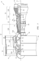
- FIG. 1 shows a side partial cross-section view of a gas turbine engine 10 and includes axial centerline 12, upstream airflow inlet 14, downstream airflow exhaust outlet 16, fan section 18, compressor section 20 (with low pressure compressor (“LPC”) section 20A and high pressure compressor (“HPC”) section 20B), combustor section 22, turbine section 24 (with high pressure turbine (“HPT”) section 24A and low pressure turbine (“LPT”) section 24B), engine housing 26 (with core case 28 and fan case 30), fan rotor 32, LPC rotor 34, HPC rotor 36, HPT rotor 38, LPT rotor 40, gear train 42, fan shaft 44, low speed shaft 46, high speed shaft 48, bearing compartments 50A, 50B, and 50C, plurality of bearings 52, core gas path 54, bypass gas path 56, combustion chamber 58, and combustor 60.
- LPC low pressure compressor
- HPT high pressure turbine
- LPT low pressure turbine
- the present disclosure related to an oil drainback system for the bearing compartments 50A, 50B, 50C.
- an oil drainback system for the bearing compartments 50A, 50B, 50C.
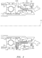
- FIG. 2 is an enlarged view of components of bearing compartment 50B of FIG. 1 , and shows surrounding buffer air cavity 62 separated from bearing compartment 50B by a seal support 64.
- a drain tube assembly 66 is schematically shown in the lower portion of this drawing and shows the position of oil being re-introduced into the bearing compartment 50B near the sump after being collected from the buffer air cavity 62.
- FIG. 3 is a completely schematic illustration of oil flow through and around the bearing compartment 50B and an accompanying oil drainback system 68.
- a sump 70 allows oil to flow to a storage tank (not shown) with filters and the like where oil can then be drawn or fed back to the bearing compartment as needed, schematically illustrated by arrow 71.
- oil which has reached the buffer air cavity 62 is collected in an oil drainback system 68 and returned to the bearing compartment 50B.
- This oil can be collected, for example by centripetal force and gravity, in a gutter system schematically illustrated at 73 and then flows at pressure typically influenced by pressure in the buffer air area 62, through an oil flow path 72 to an oil drain tube 74 which typically introduces the collected oil near sump 70.
- Oil and air in the oil flow path are typically exposed to the higher pressure which can be present in the buffer air cavity 62, and therefore gas (air) and entrained oil can frequently be introduced back into bearing compartment 50B at a high velocity from drain tube 74, which high velocity is schematically illustrated at arrow 76.
- High velocity flow 76 can interfere with proper scavenging and flow of oil through sump 70, resulting in this area of the bearing compartment becoming flooded with oil.
- an orifice 78 or other flow restriction has been placed in drain tube 74 to reduce the impact of air flow into the bearing compartment.
- orifices as small as 0.044 inches (1.12 mm) in diameter have been utilized.
- an orifice this small is extremely prone to blockage with debris that can frequently be present in the flow of air and oil from the sump.
- An in-line orifice as shown in FIG. 4 restricts air flow and this restricted flow is then able to expand into the tube after the restriction, slowing down before exiting the tube into the compartment.
- the diffusers as disclosed herein do not restrict mass flow like the orifice. Rather, they increase the flow area at the exit to allow the mass flow from the drain tube to diffuse as opposed to exiting from the tube and acting like a single jet of air/oil.
- Diffusers as disclosed herein are configured to produce in-line flow velocity less than or equal to that which is produced using an orifice in the line.
- an orifice as shown in FIG. 4 can be used and optimized until an acceptable in-line flow velocity is achieved, that is, one which does not interfere with proper flow to the sump.
- a diffuser such as those disclosed herein can be configured with side openings in various configurations to produce an in-line flow velocity less than or equal to the acceptable in-line velocity, while doing so with diffusion and larger flow openings, thereby reducing the chance of blockage due to debris.
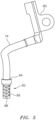
- FIG. 5 shows drain tube 74 mounted to a structure 80 which could be a portion of the structure of bearing compartment 50B such as a strut or the like.
- a diffuser device 82 can be affixed to an end 84 of drain tube 74.
- Diffuser device 82 receives flow at end 84 of drain tube 74 and diffuses and redirects flow from drain tube 74 to remove negative effects of high pressure, high velocity flow into the bearing compartment 50B.
- diffuser device 82 is also configured to minimize the possibility of blockage from debris.
- FIGS. 6-9 illustrate different non-limiting configurations of a diffuser device and these different configurations are discussed below.
- FIGS. 6 and 7 show diffuser device 82 defined by a sidewall 86 having openings 90 passing through sidewall 86. These openings are sized and arranged to direct flow laterally out of diffuser device 82, which both slows the velocity of the flow and also directs it away from the sump in the typical configuration wherein drain tube 74 is pointed at the sump.
- end wall 88 also has an end opening 92. The size and amount of side openings 90 and end opening 92 are configured to reduce velocity of flow out of drain tube 74 in the axial direction of drain tube 74, while still maintaining the size of all openings large enough to avoid potential blockage by debris.
- sidewall 86 defines a substantially cylindrical shaped structure, with openings 90 arranged around the circumference of the cylinder and also along the length of the cylinder, and with a substantially flat end wall 88 with one centered end opening 92. It should be appreciated that other positioning and configuration of the openings 90, 92 could be effective as well. In this regard, it has been found particularly useful for a ratio of flow area of openings 90 to end opening 92 to be at least high enough to produce an exit velocity from the diffuser that is equivalent to or less than the exit velocity of an in-line orifice configuration (such as is shown in FIG. 4 ) that is known to produce acceptable results, while nevertheless reducing or avoiding the risk of plugging of the diffuser from debris.
- FIGS. 6 and 7 also show an enlarged portion 94 at one end of diffuser device 82 and this serves to configure diffuser device 82 for attachment to drain tube 74.
- This can be by way of a press fit, or with a tightening strap (not shown) or any other mechanism including threads, adhesive or the like.
- maintaining diffuser device 82 as a separate part may be more practical for maintenance and cleaning as necessary, and also for the purpose of retro-fitting oil drainback systems with either a straight drain tube or a drain tube with an orifice or other flow restriction.
- FIGS. 8 and 9 illustrate configuration of a diffuser device 82 wherein openings 90 are positioned in sidewall 86 as mentioned above.
- a plurality of end openings 92 are positioned in end wall 88.
- a baffle, or central flow opening 96 is positioned within diffuser device 82 as shown.
- the plurality of end openings 92 are all off direct-center, such that even the end openings produce at least some redirection of flow along the axis of drain tube 74 and diffuser device 82.
- the configuration of these different size openings, as with other features of the diffuser can be based on achieving equivalent air exit velocity compared to a conventional orifice design which produces acceptable results with respect to flow at the sump.
- the sizing and placement of the different holes in the diffuser can be configured to produce a flow velocity of similar or less impact than what can be accomplished with an in-line orifice, while greatly reducing susceptibility to plugging due to debris.
- the oil drainback system such as that illustrated in FIG. 3 collects oil from the buffered air cavity and returns this oil back to the bearing compartment to prevent migration of the oil to areas of the engine where oil is not desired. This is accomplished with a gutter system 73 which collects such oil typically assisted by centripetal force and gravity. This collected oil then flows through gas flow path 72 to drain tube 74.
- the diffuser device as disclosed herein prevents a high velocity stream of air directly from exiting drain tube 74 at a high velocity directed at the sump, and therefore helps to avoid flooding of the sump and excessive air ingestion. Further, the diffuser device is configured to reduce the chance of blockage with debris, thereby providing an oil drainback system which addresses the issues identified above.
- any orifice or flow restriction can be removed from the drain tube and replaced with a diffuser device as disclosed herein, thereby improving functionality of the drainback system without increasing issues of blockage from debris.
Landscapes
- Engineering & Computer Science (AREA)
- General Engineering & Computer Science (AREA)
- Mechanical Engineering (AREA)
- Chemical & Material Sciences (AREA)
- Combustion & Propulsion (AREA)
- Oil, Petroleum & Natural Gas (AREA)
- Supercharger (AREA)
Claims (5)
- Diffuseur (82) pour tube de vidange d'un système de drainage d'huile, comprenant :une chambre d'écoulement configurée pour être fixée à une extrémité ouverte (84) d'un tube de vidange (74), dans lequel la chambre d'écoulement a une paroi latérale (86) et une paroi d'extrémité (88), et des ouvertures (90) dans au moins la paroi latérale (86),dans lequel la paroi latérale (86) définit un cylindre,dans lequel les ouvertures (90) sont réparties autour d'une circonférence et sur une longueur du cylindre,dans lequel la chambre d'écoulement comprend également au moins une ouverture d'extrémité (92) dans la paroi d'extrémité (88), le diffuseur comprenant également au moins un déflecteur (96) dans la chambre d'écoulement entre une extrémité d'entrée où la chambre d'écoulement se connecte au tube de vidange (74), et l'ouverture d'extrémité (92),dans lequel les ouvertures (90) dans la paroi latérale (86) sont réparties en amont et en aval du déflecteur (96),caractérisé en ce que des ouvertures (90) en amont du déflecteur (96) ont un diamètre plus petit que des ouvertures (90) en aval du déflecteur (96).
- Diffuseur selon la revendication 1, dans lequel une surface d'écoulement des ouvertures (90) dans la paroi latérale est supérieure à une surface d'écoulement de l'ouverture d'extrémité (92) .
- Système de drainage d'huile pour compartiment de palier d'un moteur à turbine à gaz, comprenant :un compartiment de palier (50A, 50B, 50C) ;une zone d'air tampon autour du compartiment de palier (50A, 50B, 50C) ;un puisard (70) pour récupérer l'huile du compartiment de palier (50A, 50B, 50C) ;un système de gouttière (73) pour collecter l'huile de la zone d'air tampon ;un chemin d'écoulement d'huile (72) relié au système de gouttière (73) et exposé à la pression à l'intérieur de la zone d'air tampon ;un tube de vidange (74) relié au chemin d'écoulement d'huile (72) et se prolongeant dans le compartiment de palier (50A, 50B, 50C) pour renvoyer l'huile collectée depuis la zone d'air tampon vers le compartiment de palier (50A, 50B, 50C) ; etun diffuseur (82) selon une quelconque revendication précédente pour diffuser le flux de gaz provenant du tube de vidange (74) à l'intérieur du compartiment de palier (50A, 50B, 50C).
- Procédé d'amélioration d'un système de drainage d'huile pour un moteur à turbine à gaz, dans lequel le système de drainage d'huile comprendun compartiment de palier (50A, 50B, 50C) ;une zone d'air tampon autour du compartiment de palier (50A, 50B, 50C) ;un puisard (70) pour récupérer l'huile du compartiment de palier (50A, 50B, 50C) ; un système de gouttière (73) pour collecter l'huile de la zone d'air tampon ;un chemin d'écoulement d'huile (72) relié au système de gouttière (73) et exposé à la pression à l'intérieur de la zone d'air tampon ; etun tube de vidange (74) relié au chemin d'écoulement d'huile (72) et se prolongeant dans le compartiment de palier (50A, 50B, 50C) pour renvoyer l'huile collectée depuis la zone d'air tampon vers le compartiment de palier (50A, 50B, 50C),dans lequel le procédé comprend le montage d'un diffuseur (82) sur une extrémité ouverte (84) du tube de vidange (74),dans lequel le diffuseur (82) comprend une chambre d'écoulement configurée pour être fixée à l'extrémité ouverte (84) du tube de vidange (74), la chambre d'écoulement ayant une paroi latérale (86) et une paroi d'extrémité (88), et des ouvertures (90) dans au moins la paroi latérale (86),dans lequel la paroi latérale (86) définit un cylindre,dans lequel les ouvertures (90) sont réparties autour d'une circonférence et sur une longueur du cylindredans lequel la chambre d'écoulement comprend également au moins une ouverture d'extrémité (92) dans la paroi d'extrémité (88), le diffuseur comprenant également au moins un déflecteur (96) dans la chambre d'écoulement entre une extrémité d'entrée où la chambre d'écoulement se connecte au tube de vidange (74), et l'ouverture d'extrémité (92),dans lequel les ouvertures (90) dans la paroi latérale (86) sont réparties en amont et en aval du déflecteur (96),caractérisé en ce que des ouvertures (90) en amont du déflecteur (96) ont un diamètre plus petit que des ouvertures (90) en aval du déflecteur (96).
- Procédé selon la revendication 4, dans lequel le tube de vidange (74) contient un orifice (78) pour restreindre l'écoulement à travers le tube de vidange (74), et dans lequel le procédé comprend également le retrait de l'orifice (78) du tube de vidange (74) avant l'étape de montage.
Applications Claiming Priority (2)
| Application Number | Priority Date | Filing Date | Title |
|---|---|---|---|
| US201962897507P | 2019-09-09 | 2019-09-09 | |
| US16/572,806 US11506079B2 (en) | 2019-09-09 | 2019-09-17 | Fluid diffusion device for sealed bearing compartment drainback system |
Publications (2)
| Publication Number | Publication Date |
|---|---|
| EP3789593A1 EP3789593A1 (fr) | 2021-03-10 |
| EP3789593B1 true EP3789593B1 (fr) | 2024-10-30 |
Family
ID=72355930
Family Applications (1)
| Application Number | Title | Priority Date | Filing Date |
|---|---|---|---|
| EP20194406.3A Active EP3789593B1 (fr) | 2019-09-09 | 2020-09-03 | Diffuseur pour un système de drainage d'huile pour un compartiment de palier d'un moteur à turbine à gaz et procédé d'amélioration d'un système de drainage d'huile pour un moteur à turbine à gaz |
Country Status (2)
| Country | Link |
|---|---|
| US (1) | US11506079B2 (fr) |
| EP (1) | EP3789593B1 (fr) |
Families Citing this family (2)
| Publication number | Priority date | Publication date | Assignee | Title |
|---|---|---|---|---|
| US11970972B2 (en) | 2019-10-23 | 2024-04-30 | Rtx Corporation | Windage blocker for oil routing |
| US11719127B2 (en) | 2019-10-23 | 2023-08-08 | Raytheon Technologies Corporation | Oil drainback assembly for a bearing compartment of a gas turbine engine |
Citations (1)
| Publication number | Priority date | Publication date | Assignee | Title |
|---|---|---|---|---|
| EP2963249A1 (fr) * | 2014-07-01 | 2016-01-06 | United Technologies Corporation | Moteur à turbine à gaz avec soufflante à engrenage et désaérateur d'huile |
Family Cites Families (30)
| Publication number | Priority date | Publication date | Assignee | Title |
|---|---|---|---|---|
| US3500869A (en) | 1967-08-02 | 1970-03-17 | American Cyanamid Co | Flexible flattened tubular open-ended article |
| ES362990A1 (es) | 1968-01-24 | 1971-02-16 | Snam Progetti | Perfeccionamientos en la fabricacion de composiciones li- quidas utilizadas en el corte de metales. |
| US4862995A (en) * | 1987-06-04 | 1989-09-05 | Steve Faria | Oil discharge diffuser |
| DE4041389A1 (de) | 1990-12-21 | 1992-06-25 | Kugelfischer G Schaefer & Co | Vorrichtung zum entfernen von oel aus ringraeumen |
| US5813493A (en) | 1997-04-15 | 1998-09-29 | Dana Corporation | Lubrication fluid deflector/baffle for a motor vehicle axle assembly |
| GB9903611D0 (en) | 1999-02-18 | 1999-04-07 | Perkins Engines Co Ltd | Breather baffle |
| JP4314627B2 (ja) | 1999-11-12 | 2009-08-19 | 株式会社Ihi | 過給機の軸受装置 |
| US6996968B2 (en) | 2003-12-17 | 2006-02-14 | United Technologies Corporation | Bifurcated oil scavenge system for a gas turbine engine |
| US7017546B1 (en) | 2004-10-28 | 2006-03-28 | General Motors Corporation | Dry sump oil tank assembly |
| US8292510B2 (en) * | 2006-09-28 | 2012-10-23 | United Technologies Corporation | Dual mode scavenge scoop |
| US9033108B2 (en) | 2006-12-22 | 2015-05-19 | Rolls-Royce Corporation | Lubricant flow suppressor |
| CN201241753Y (zh) | 2008-08-22 | 2009-05-20 | 寿光市康跃增压器有限公司 | 一种涡轮增压器涡旋回流轴承体 |
| GB0816562D0 (en) | 2008-09-11 | 2008-10-15 | Rolls Royce Plc | Lubricant scavenge arrangement |
| US8621839B2 (en) * | 2009-09-28 | 2014-01-07 | Pratt & Whitney Canada Corp. | Gas turbine engine breather exhaust oil collector |
| US8893469B2 (en) | 2011-06-22 | 2014-11-25 | United Technologies Corporation | Oil bypass channel deaerator for a geared turbofan engine |
| US8500869B1 (en) * | 2012-06-21 | 2013-08-06 | Hamilton Sundstrand Corporation | Anti-rotation deaerator outlet diffuser |
| PL402185A1 (pl) | 2012-12-21 | 2014-06-23 | General Electric Company | Połączona instalacja ściekowa do silników turbinowych |
| EP2946131B1 (fr) | 2013-01-15 | 2020-03-04 | United Technologies Corporation | Turbine à gaz |
| CN203463452U (zh) | 2013-08-27 | 2014-03-05 | 永嘉县永乐高中压标准件有限公司 | 一种放油螺栓 |
| US9835086B2 (en) | 2013-10-08 | 2017-12-05 | United Technologies Corporation | Low loss oil accumulator assembly |
| US9464572B2 (en) | 2013-12-20 | 2016-10-11 | Pratt & Whitney Canada Corp. | Oil tank and scavenge pipe assembly of a gas turbine engine and method of delivering an oil and air mixture to same |
| WO2015127944A1 (fr) * | 2014-02-26 | 2015-09-03 | Volvo Truck Corporation | Unité de turbomoteur à échangeur de chaleur |
| CN203730508U (zh) | 2014-03-13 | 2014-07-23 | 温州市强杰不锈钢标准件有限公司 | 放油螺栓 |
| FR3037614B1 (fr) | 2015-06-22 | 2017-07-07 | Snecma | Drain pour carter d'echappement de turbomachine |
| CN108204281B (zh) * | 2016-12-20 | 2019-08-27 | 中国航发商用航空发动机有限责任公司 | 油气分离器、油气分离系统及航空发动机 |
| CN207750348U (zh) | 2017-11-01 | 2018-08-21 | 海盐哈特惠机械五金制品有限公司 | 一种注油螺栓 |
| WO2019147778A1 (fr) | 2018-01-26 | 2019-08-01 | Siemens Aktiengesellschaft | Ensemble palier lisse avec élément de facilitation d'évacuation |
| US10865657B2 (en) * | 2018-04-23 | 2020-12-15 | Pratt & Whitney Canada Corp. | Sealing assembly for a gas turbine engine |
| US11970972B2 (en) * | 2019-10-23 | 2024-04-30 | Rtx Corporation | Windage blocker for oil routing |
| US11719127B2 (en) | 2019-10-23 | 2023-08-08 | Raytheon Technologies Corporation | Oil drainback assembly for a bearing compartment of a gas turbine engine |
-
2019
- 2019-09-17 US US16/572,806 patent/US11506079B2/en active Active
-
2020
- 2020-09-03 EP EP20194406.3A patent/EP3789593B1/fr active Active
Patent Citations (1)
| Publication number | Priority date | Publication date | Assignee | Title |
|---|---|---|---|---|
| EP2963249A1 (fr) * | 2014-07-01 | 2016-01-06 | United Technologies Corporation | Moteur à turbine à gaz avec soufflante à engrenage et désaérateur d'huile |
Also Published As
| Publication number | Publication date |
|---|---|
| US11506079B2 (en) | 2022-11-22 |
| EP3789593A1 (fr) | 2021-03-10 |
| US20210071677A1 (en) | 2021-03-11 |
Similar Documents
| Publication | Publication Date | Title |
|---|---|---|
| US12018574B2 (en) | Geared gas turbine engine with oil deaerator and air removal | |
| CA2714861C (fr) | Collector d'huile d'echappement de reniflard de turbine a gaz | |
| JP5188408B2 (ja) | 脱油装置および該装置を備えるターボ機械 | |
| US7827798B2 (en) | System for ventilating a combustion chamber wall in a turbomachine | |
| RU2500892C2 (ru) | Ротор компрессора газотурбинного двигателя и газотурбинный двигатель | |
| US8985277B2 (en) | Case with integral lubricant scavenge passage | |
| US6893478B2 (en) | Air/oil separator | |
| US7435290B2 (en) | Centrifugal gas/liquid separators | |
| CA2676831C (fr) | Systeme de vidange d'huile ayant un amortisseur de turbulence pour moteurs a turbine a gaz | |
| EP2586534B1 (fr) | Séparateur centrifuge, moteur à combustion interne et ensemble de séparateur centrifuge et procédé de séparation des contaminants d'un gaz de carter | |
| US20180038243A1 (en) | Oil cooling systems for a gas turbine engine | |
| EP3812603B1 (fr) | Ensemble de retour d'écoulement d'huile pour un compartiment de palier d'un moteur à turbine à gaz | |
| EP3789593B1 (fr) | Diffuseur pour un système de drainage d'huile pour un compartiment de palier d'un moteur à turbine à gaz et procédé d'amélioration d'un système de drainage d'huile pour un moteur à turbine à gaz | |
| JP2005507044A (ja) | 補助動力装置設備のための受動型冷却システム | |
| JP2008014299A (ja) | ターボ機械およびシールへの流体供給方法 | |
| EP3550126B1 (fr) | Turboréacteur à engrenages ayant une ventilation d'aspiration d'air améliorée | |
| EP1933041A2 (fr) | Chambre de tranquillisation d'entrée pour moteur de turbine à gaz | |
| CA2990903C (fr) | Appareil de separation air-huile | |
| US4098074A (en) | Combustor diffuser for turbine type power plant and construction thereof | |
| JP2001289052A (ja) | ターボ過給機 | |
| JPH05240022A (ja) | ブローバイガス中のオイル除去装置 | |
| US20230130641A1 (en) | Lubrication system of aircraft engine | |
| KR101942355B1 (ko) | 터보차져의 오일미스트 및 흄 처리장치 | |
| KR101916236B1 (ko) | 터보차져의 오일미스트 및 흄 처리장치 | |
| CN108431374A (zh) | 用于分离润滑油流的装置和带有这样的装置的废气涡轮增压器 |
Legal Events
| Date | Code | Title | Description |
|---|---|---|---|
| PUAI | Public reference made under article 153(3) epc to a published international application that has entered the european phase |
Free format text: ORIGINAL CODE: 0009012 |
|
| STAA | Information on the status of an ep patent application or granted ep patent |
Free format text: STATUS: THE APPLICATION HAS BEEN PUBLISHED |
|
| AK | Designated contracting states |
Kind code of ref document: A1 Designated state(s): AL AT BE BG CH CY CZ DE DK EE ES FI FR GB GR HR HU IE IS IT LI LT LU LV MC MK MT NL NO PL PT RO RS SE SI SK SM TR |
|
| AX | Request for extension of the european patent |
Extension state: BA ME |
|
| STAA | Information on the status of an ep patent application or granted ep patent |
Free format text: STATUS: REQUEST FOR EXAMINATION WAS MADE |
|
| 17P | Request for examination filed |
Effective date: 20210906 |
|
| RBV | Designated contracting states (corrected) |
Designated state(s): AL AT BE BG CH CY CZ DE DK EE ES FI FR GB GR HR HU IE IS IT LI LT LU LV MC MK MT NL NO PL PT RO RS SE SI SK SM TR |
|
| STAA | Information on the status of an ep patent application or granted ep patent |
Free format text: STATUS: EXAMINATION IS IN PROGRESS |
|
| 17Q | First examination report despatched |
Effective date: 20220901 |
|
| RAP3 | Party data changed (applicant data changed or rights of an application transferred) |
Owner name: RTX CORPORATION |
|
| RIC1 | Information provided on ipc code assigned before grant |
Ipc: F01M 11/04 20060101ALN20240307BHEP Ipc: F16C 33/66 20060101ALI20240307BHEP Ipc: F01M 11/00 20060101ALI20240307BHEP Ipc: F16N 31/00 20060101ALI20240307BHEP Ipc: F01D 25/18 20060101AFI20240307BHEP |
|
| GRAP | Despatch of communication of intention to grant a patent |
Free format text: ORIGINAL CODE: EPIDOSNIGR1 |
|
| STAA | Information on the status of an ep patent application or granted ep patent |
Free format text: STATUS: GRANT OF PATENT IS INTENDED |
|
| INTG | Intention to grant announced |
Effective date: 20240425 |
|
| GRAS | Grant fee paid |
Free format text: ORIGINAL CODE: EPIDOSNIGR3 |
|
| GRAA | (expected) grant |
Free format text: ORIGINAL CODE: 0009210 |
|
| STAA | Information on the status of an ep patent application or granted ep patent |
Free format text: STATUS: THE PATENT HAS BEEN GRANTED |
|
| AK | Designated contracting states |
Kind code of ref document: B1 Designated state(s): AL AT BE BG CH CY CZ DE DK EE ES FI FR GB GR HR HU IE IS IT LI LT LU LV MC MK MT NL NO PL PT RO RS SE SI SK SM TR |
|
| REG | Reference to a national code |
Ref country code: GB Ref legal event code: FG4D |
|
| REG | Reference to a national code |
Ref country code: CH Ref legal event code: EP |
|
| REG | Reference to a national code |
Ref country code: IE Ref legal event code: FG4D |
|
| REG | Reference to a national code |
Ref country code: DE Ref legal event code: R096 Ref document number: 602020040180 Country of ref document: DE |
|
| REG | Reference to a national code |
Ref country code: LT Ref legal event code: MG9D |
|
| REG | Reference to a national code |
Ref country code: NL Ref legal event code: MP Effective date: 20241030 |
|
| PG25 | Lapsed in a contracting state [announced via postgrant information from national office to epo] |
Ref country code: IS Free format text: LAPSE BECAUSE OF FAILURE TO SUBMIT A TRANSLATION OF THE DESCRIPTION OR TO PAY THE FEE WITHIN THE PRESCRIBED TIME-LIMIT Effective date: 20250228 Ref country code: HR Free format text: LAPSE BECAUSE OF FAILURE TO SUBMIT A TRANSLATION OF THE DESCRIPTION OR TO PAY THE FEE WITHIN THE PRESCRIBED TIME-LIMIT Effective date: 20241030 Ref country code: PT Free format text: LAPSE BECAUSE OF FAILURE TO SUBMIT A TRANSLATION OF THE DESCRIPTION OR TO PAY THE FEE WITHIN THE PRESCRIBED TIME-LIMIT Effective date: 20250228 |
|
| PG25 | Lapsed in a contracting state [announced via postgrant information from national office to epo] |
Ref country code: FI Free format text: LAPSE BECAUSE OF FAILURE TO SUBMIT A TRANSLATION OF THE DESCRIPTION OR TO PAY THE FEE WITHIN THE PRESCRIBED TIME-LIMIT Effective date: 20241030 Ref country code: NL Free format text: LAPSE BECAUSE OF FAILURE TO SUBMIT A TRANSLATION OF THE DESCRIPTION OR TO PAY THE FEE WITHIN THE PRESCRIBED TIME-LIMIT Effective date: 20241030 |
|
| REG | Reference to a national code |
Ref country code: AT Ref legal event code: MK05 Ref document number: 1737052 Country of ref document: AT Kind code of ref document: T Effective date: 20241030 |
|
| PG25 | Lapsed in a contracting state [announced via postgrant information from national office to epo] |
Ref country code: BG Free format text: LAPSE BECAUSE OF FAILURE TO SUBMIT A TRANSLATION OF THE DESCRIPTION OR TO PAY THE FEE WITHIN THE PRESCRIBED TIME-LIMIT Effective date: 20241030 |
|
| PG25 | Lapsed in a contracting state [announced via postgrant information from national office to epo] |
Ref country code: ES Free format text: LAPSE BECAUSE OF FAILURE TO SUBMIT A TRANSLATION OF THE DESCRIPTION OR TO PAY THE FEE WITHIN THE PRESCRIBED TIME-LIMIT Effective date: 20241030 |
|
| PG25 | Lapsed in a contracting state [announced via postgrant information from national office to epo] |
Ref country code: NO Free format text: LAPSE BECAUSE OF FAILURE TO SUBMIT A TRANSLATION OF THE DESCRIPTION OR TO PAY THE FEE WITHIN THE PRESCRIBED TIME-LIMIT Effective date: 20250130 |
|
| PG25 | Lapsed in a contracting state [announced via postgrant information from national office to epo] |
Ref country code: LV Free format text: LAPSE BECAUSE OF FAILURE TO SUBMIT A TRANSLATION OF THE DESCRIPTION OR TO PAY THE FEE WITHIN THE PRESCRIBED TIME-LIMIT Effective date: 20241030 Ref country code: GR Free format text: LAPSE BECAUSE OF FAILURE TO SUBMIT A TRANSLATION OF THE DESCRIPTION OR TO PAY THE FEE WITHIN THE PRESCRIBED TIME-LIMIT Effective date: 20250131 Ref country code: AT Free format text: LAPSE BECAUSE OF FAILURE TO SUBMIT A TRANSLATION OF THE DESCRIPTION OR TO PAY THE FEE WITHIN THE PRESCRIBED TIME-LIMIT Effective date: 20241030 |
|
| PG25 | Lapsed in a contracting state [announced via postgrant information from national office to epo] |
Ref country code: PL Free format text: LAPSE BECAUSE OF FAILURE TO SUBMIT A TRANSLATION OF THE DESCRIPTION OR TO PAY THE FEE WITHIN THE PRESCRIBED TIME-LIMIT Effective date: 20241030 |
|
| PG25 | Lapsed in a contracting state [announced via postgrant information from national office to epo] |
Ref country code: RS Free format text: LAPSE BECAUSE OF FAILURE TO SUBMIT A TRANSLATION OF THE DESCRIPTION OR TO PAY THE FEE WITHIN THE PRESCRIBED TIME-LIMIT Effective date: 20250130 |
|
| PG25 | Lapsed in a contracting state [announced via postgrant information from national office to epo] |
Ref country code: SM Free format text: LAPSE BECAUSE OF FAILURE TO SUBMIT A TRANSLATION OF THE DESCRIPTION OR TO PAY THE FEE WITHIN THE PRESCRIBED TIME-LIMIT Effective date: 20241030 |
|
| PG25 | Lapsed in a contracting state [announced via postgrant information from national office to epo] |
Ref country code: DK Free format text: LAPSE BECAUSE OF FAILURE TO SUBMIT A TRANSLATION OF THE DESCRIPTION OR TO PAY THE FEE WITHIN THE PRESCRIBED TIME-LIMIT Effective date: 20241030 |
|
| PG25 | Lapsed in a contracting state [announced via postgrant information from national office to epo] |
Ref country code: EE Free format text: LAPSE BECAUSE OF FAILURE TO SUBMIT A TRANSLATION OF THE DESCRIPTION OR TO PAY THE FEE WITHIN THE PRESCRIBED TIME-LIMIT Effective date: 20241030 |
|
| PG25 | Lapsed in a contracting state [announced via postgrant information from national office to epo] |
Ref country code: RO Free format text: LAPSE BECAUSE OF FAILURE TO SUBMIT A TRANSLATION OF THE DESCRIPTION OR TO PAY THE FEE WITHIN THE PRESCRIBED TIME-LIMIT Effective date: 20241030 |
|
| PG25 | Lapsed in a contracting state [announced via postgrant information from national office to epo] |
Ref country code: SK Free format text: LAPSE BECAUSE OF FAILURE TO SUBMIT A TRANSLATION OF THE DESCRIPTION OR TO PAY THE FEE WITHIN THE PRESCRIBED TIME-LIMIT Effective date: 20241030 |
|
| PG25 | Lapsed in a contracting state [announced via postgrant information from national office to epo] |
Ref country code: CZ Free format text: LAPSE BECAUSE OF FAILURE TO SUBMIT A TRANSLATION OF THE DESCRIPTION OR TO PAY THE FEE WITHIN THE PRESCRIBED TIME-LIMIT Effective date: 20241030 |
|
| PG25 | Lapsed in a contracting state [announced via postgrant information from national office to epo] |
Ref country code: IT Free format text: LAPSE BECAUSE OF FAILURE TO SUBMIT A TRANSLATION OF THE DESCRIPTION OR TO PAY THE FEE WITHIN THE PRESCRIBED TIME-LIMIT Effective date: 20241030 |
|
| REG | Reference to a national code |
Ref country code: DE Ref legal event code: R097 Ref document number: 602020040180 Country of ref document: DE |
|
| PLBE | No opposition filed within time limit |
Free format text: ORIGINAL CODE: 0009261 |
|
| STAA | Information on the status of an ep patent application or granted ep patent |
Free format text: STATUS: NO OPPOSITION FILED WITHIN TIME LIMIT |
|
| PG25 | Lapsed in a contracting state [announced via postgrant information from national office to epo] |
Ref country code: SE Free format text: LAPSE BECAUSE OF FAILURE TO SUBMIT A TRANSLATION OF THE DESCRIPTION OR TO PAY THE FEE WITHIN THE PRESCRIBED TIME-LIMIT Effective date: 20241030 |
|
| 26N | No opposition filed |
Effective date: 20250731 |
|
| PGFP | Annual fee paid to national office [announced via postgrant information from national office to epo] |
Ref country code: DE Payment date: 20250820 Year of fee payment: 6 |
|
| PGFP | Annual fee paid to national office [announced via postgrant information from national office to epo] |
Ref country code: GB Payment date: 20250822 Year of fee payment: 6 |
|
| PGFP | Annual fee paid to national office [announced via postgrant information from national office to epo] |
Ref country code: FR Payment date: 20250820 Year of fee payment: 6 |