EP3789603B1 - Elektrische hilfskraftunterstützung für motorneustart im flug - Google Patents
Elektrische hilfskraftunterstützung für motorneustart im flug Download PDFInfo
- Publication number
- EP3789603B1 EP3789603B1 EP20190770.6A EP20190770A EP3789603B1 EP 3789603 B1 EP3789603 B1 EP 3789603B1 EP 20190770 A EP20190770 A EP 20190770A EP 3789603 B1 EP3789603 B1 EP 3789603B1
- Authority
- EP
- European Patent Office
- Prior art keywords
- engine
- gas turbine
- speed spool
- flight
- power
- Prior art date
- Legal status (The legal status is an assumption and is not a legal conclusion. Google has not performed a legal analysis and makes no representation as to the accuracy of the status listed.)
- Active
Links
Images


Classifications
-
- F—MECHANICAL ENGINEERING; LIGHTING; HEATING; WEAPONS; BLASTING
- F02—COMBUSTION ENGINES; HOT-GAS OR COMBUSTION-PRODUCT ENGINE PLANTS
- F02C—GAS-TURBINE PLANTS; AIR INTAKES FOR JET-PROPULSION PLANTS; CONTROLLING FUEL SUPPLY IN AIR-BREATHING JET-PROPULSION PLANTS
- F02C7/00—Features, components parts, details or accessories, not provided for in, or of interest apart form groups F02C1/00 - F02C6/00; Air intakes for jet-propulsion plants
- F02C7/26—Starting; Ignition
- F02C7/262—Restarting after flame-out
-
- B—PERFORMING OPERATIONS; TRANSPORTING
- B64—AIRCRAFT; AVIATION; COSMONAUTICS
- B64D—EQUIPMENT FOR FITTING IN OR TO AIRCRAFT; FLIGHT SUITS; PARACHUTES; ARRANGEMENT OR MOUNTING OF POWER PLANTS OR PROPULSION TRANSMISSIONS IN AIRCRAFT
- B64D27/00—Arrangement or mounting of power plants in aircraft; Aircraft characterised by the type or position of power plants
- B64D27/02—Aircraft characterised by the type or position of power plants
- B64D27/30—Aircraft characterised by electric power plants
- B64D27/33—Hybrid electric aircraft
-
- B—PERFORMING OPERATIONS; TRANSPORTING
- B64—AIRCRAFT; AVIATION; COSMONAUTICS
- B64D—EQUIPMENT FOR FITTING IN OR TO AIRCRAFT; FLIGHT SUITS; PARACHUTES; ARRANGEMENT OR MOUNTING OF POWER PLANTS OR PROPULSION TRANSMISSIONS IN AIRCRAFT
- B64D27/00—Arrangement or mounting of power plants in aircraft; Aircraft characterised by the type or position of power plants
- B64D27/02—Aircraft characterised by the type or position of power plants
- B64D27/30—Aircraft characterised by electric power plants
- B64D27/35—Arrangements for on-board electric energy production, distribution, recovery or storage
- B64D27/357—Arrangements for on-board electric energy production, distribution, recovery or storage using batteries
-
- B—PERFORMING OPERATIONS; TRANSPORTING
- B64—AIRCRAFT; AVIATION; COSMONAUTICS
- B64D—EQUIPMENT FOR FITTING IN OR TO AIRCRAFT; FLIGHT SUITS; PARACHUTES; ARRANGEMENT OR MOUNTING OF POWER PLANTS OR PROPULSION TRANSMISSIONS IN AIRCRAFT
- B64D31/00—Power plant control systems; Arrangement of power plant control systems in aircraft
- B64D31/16—Power plant control systems; Arrangement of power plant control systems in aircraft for electric power plants
- B64D31/18—Power plant control systems; Arrangement of power plant control systems in aircraft for electric power plants for hybrid-electric power plants
-
- F—MECHANICAL ENGINEERING; LIGHTING; HEATING; WEAPONS; BLASTING
- F01—MACHINES OR ENGINES IN GENERAL; ENGINE PLANTS IN GENERAL; STEAM ENGINES
- F01D—NON-POSITIVE DISPLACEMENT MACHINES OR ENGINES, e.g. STEAM TURBINES
- F01D19/00—Starting of machines or engines; Regulating, controlling, or safety means in connection therewith
-
- F—MECHANICAL ENGINEERING; LIGHTING; HEATING; WEAPONS; BLASTING
- F02—COMBUSTION ENGINES; HOT-GAS OR COMBUSTION-PRODUCT ENGINE PLANTS
- F02C—GAS-TURBINE PLANTS; AIR INTAKES FOR JET-PROPULSION PLANTS; CONTROLLING FUEL SUPPLY IN AIR-BREATHING JET-PROPULSION PLANTS
- F02C6/00—Plural gas-turbine plants; Combinations of gas-turbine plants with other apparatus; Adaptations of gas-turbine plants for special use
- F02C6/20—Adaptations of gas-turbine plants for driving vehicles
-
- F—MECHANICAL ENGINEERING; LIGHTING; HEATING; WEAPONS; BLASTING
- F02—COMBUSTION ENGINES; HOT-GAS OR COMBUSTION-PRODUCT ENGINE PLANTS
- F02C—GAS-TURBINE PLANTS; AIR INTAKES FOR JET-PROPULSION PLANTS; CONTROLLING FUEL SUPPLY IN AIR-BREATHING JET-PROPULSION PLANTS
- F02C7/00—Features, components parts, details or accessories, not provided for in, or of interest apart form groups F02C1/00 - F02C6/00; Air intakes for jet-propulsion plants
- F02C7/26—Starting; Ignition
- F02C7/268—Starting drives for the rotor, acting directly on the rotor of the gas turbine to be started
-
- F—MECHANICAL ENGINEERING; LIGHTING; HEATING; WEAPONS; BLASTING
- F02—COMBUSTION ENGINES; HOT-GAS OR COMBUSTION-PRODUCT ENGINE PLANTS
- F02K—JET-PROPULSION PLANTS
- F02K5/00—Plants including an engine, other than a gas turbine, driving a compressor or a ducted fan
-
- B—PERFORMING OPERATIONS; TRANSPORTING
- B64—AIRCRAFT; AVIATION; COSMONAUTICS
- B64D—EQUIPMENT FOR FITTING IN OR TO AIRCRAFT; FLIGHT SUITS; PARACHUTES; ARRANGEMENT OR MOUNTING OF POWER PLANTS OR PROPULSION TRANSMISSIONS IN AIRCRAFT
- B64D27/00—Arrangement or mounting of power plants in aircraft; Aircraft characterised by the type or position of power plants
- B64D27/02—Aircraft characterised by the type or position of power plants
- B64D27/026—Aircraft characterised by the type or position of power plants comprising different types of power plants, e.g. combination of a piston engine and a gas-turbine
-
- F—MECHANICAL ENGINEERING; LIGHTING; HEATING; WEAPONS; BLASTING
- F05—INDEXING SCHEMES RELATING TO ENGINES OR PUMPS IN VARIOUS SUBCLASSES OF CLASSES F01-F04
- F05D—INDEXING SCHEME FOR ASPECTS RELATING TO NON-POSITIVE-DISPLACEMENT MACHINES OR ENGINES, GAS-TURBINES OR JET-PROPULSION PLANTS
- F05D2220/00—Application
- F05D2220/30—Application in turbines
- F05D2220/32—Application in turbines in gas turbines
- F05D2220/323—Application in turbines in gas turbines for aircraft propulsion, e.g. jet engines
-
- F—MECHANICAL ENGINEERING; LIGHTING; HEATING; WEAPONS; BLASTING
- F05—INDEXING SCHEMES RELATING TO ENGINES OR PUMPS IN VARIOUS SUBCLASSES OF CLASSES F01-F04
- F05D—INDEXING SCHEME FOR ASPECTS RELATING TO NON-POSITIVE-DISPLACEMENT MACHINES OR ENGINES, GAS-TURBINES OR JET-PROPULSION PLANTS
- F05D2220/00—Application
- F05D2220/70—Application in combination with
- F05D2220/76—Application in combination with an electrical generator
-
- F—MECHANICAL ENGINEERING; LIGHTING; HEATING; WEAPONS; BLASTING
- F05—INDEXING SCHEMES RELATING TO ENGINES OR PUMPS IN VARIOUS SUBCLASSES OF CLASSES F01-F04
- F05D—INDEXING SCHEME FOR ASPECTS RELATING TO NON-POSITIVE-DISPLACEMENT MACHINES OR ENGINES, GAS-TURBINES OR JET-PROPULSION PLANTS
- F05D2260/00—Function
- F05D2260/85—Starting
-
- F—MECHANICAL ENGINEERING; LIGHTING; HEATING; WEAPONS; BLASTING
- F05—INDEXING SCHEMES RELATING TO ENGINES OR PUMPS IN VARIOUS SUBCLASSES OF CLASSES F01-F04
- F05D—INDEXING SCHEME FOR ASPECTS RELATING TO NON-POSITIVE-DISPLACEMENT MACHINES OR ENGINES, GAS-TURBINES OR JET-PROPULSION PLANTS
- F05D2270/00—Control
- F05D2270/01—Purpose of the control system
- F05D2270/09—Purpose of the control system to cope with emergencies
- F05D2270/091—Purpose of the control system to cope with emergencies in particular sudden load loss
-
- F—MECHANICAL ENGINEERING; LIGHTING; HEATING; WEAPONS; BLASTING
- F05—INDEXING SCHEMES RELATING TO ENGINES OR PUMPS IN VARIOUS SUBCLASSES OF CLASSES F01-F04
- F05D—INDEXING SCHEME FOR ASPECTS RELATING TO NON-POSITIVE-DISPLACEMENT MACHINES OR ENGINES, GAS-TURBINES OR JET-PROPULSION PLANTS
- F05D2270/00—Control
- F05D2270/01—Purpose of the control system
- F05D2270/10—Purpose of the control system to cope with, or avoid, compressor flow instabilities
- F05D2270/101—Compressor surge or stall
-
- Y—GENERAL TAGGING OF NEW TECHNOLOGICAL DEVELOPMENTS; GENERAL TAGGING OF CROSS-SECTIONAL TECHNOLOGIES SPANNING OVER SEVERAL SECTIONS OF THE IPC; TECHNICAL SUBJECTS COVERED BY FORMER USPC CROSS-REFERENCE ART COLLECTIONS [XRACs] AND DIGESTS
- Y02—TECHNOLOGIES OR APPLICATIONS FOR MITIGATION OR ADAPTATION AGAINST CLIMATE CHANGE
- Y02T—CLIMATE CHANGE MITIGATION TECHNOLOGIES RELATED TO TRANSPORTATION
- Y02T50/00—Aeronautics or air transport
- Y02T50/60—Efficient propulsion technologies, e.g. for aircraft
Definitions
- the subject matter disclosed herein generally relates to in-flight engine re-start of an aircraft engine and, more particularly, to a method and an apparatus for control for hybrid electric engine and/or an engine with electric power assist for in-flight re-start.
- the engine After an engine shutdown during flight, the engine is required to re-start within a "windmill" re-start envelope, that is defined by a range of altitude and airspeed where the engine must re-start with no external power source (APU or opposite engine cross-bleed). This may also be referred to as in-flight windmill re-start envelope.
- EP3415436 discloses a propulsion system for an aircraft where an electric energy storage unit supplies an electric machine with energy to assist with a mid-air restart in response to an unscheduled shutdown of the aircraft.
- US2012167590 discloses an aircraft/gas turbine engine where electrical power is generated by the low speed spool, which is used to rotate the high speed spool during a windmill restart of the engine.
- FR 3 056 558 A1 discloses another prior art hybrid electric propulsion system.
- a hybrid electric propulsion system according to claim 1 is provided.
- the controller may be a full authority digital engine control (FADEC) that has full authority over the power source and the electric motor.
- FADEC full authority digital engine control
- a technical effect of the apparatus, systems and methods is achieved by providing electric power to the high speed spool of the hybrid electric propulsion system in order to expand an in-flight windmill re-start envelope to include airspeeds and altitudes that would be excluded from an in-flight windmill re-start envelope that does not rely upon augmented rotational power to the high speed spool, wherein the controller has full authority of the power source and the electric motor.
- the power source may be at least one of the following: a battery; a super capacitor; and an ultra capacitor.
- the motor may be connected to an engine accessory gearbox that is operably coupled to the high speed spool.
- the motor may be connected to an engine accessory gearbox that is operably coupled to the high speed spool.
- the motor may be connected to an engine accessory gearbox that is operably coupled to the high speed spool.
- the motor may be configured to only augment rotational power of the high speed spool during the detected in-flight windmill re-start condition of the gas turbine engine.
- the motor may be configured to only augment rotational power of the high speed spool during the detected in-flight windmill re-start condition of the gas turbine engine.
- the motor may be configured to only augment rotational power of the high speed spool during the detected in-flight windmill re-start condition of the gas turbine engine.
- a method for stabilizing a compressor section of a gas turbine engine during an in-flight re-start of the gas turbine engine comprising: providing power assist to a high speed spool of the gas turbine engine via an electric motor operably coupled to the high speed spool during the in-flight re-start of the gas turbine engine; determining, based at least in part on an altitude and airspeed associated with the hybrid electric propulsion system, that an opposite engine power assist is prohibited; detecting an in-flight windmill re-start condition of the gas turbine engine, wherein the in-flight windmill re-start condition of the gas turbine engine is based at least in part on the determination that opposite engine power assist is prohibited; wherein power is caused to be supplied from a power source to the electric motor by a controller; wherein the controller and the electric motor provide compressor stability to a high pressure compressor of the high speed spool during the in-flight re-start such that high pressure compressor bleed valves are not required for the in-f
- the in-flight re-start of the gas turbine engine may be autonomous.
- the controller may have full authority of the power source and the electric motor.
- the controller may be a full authority digital engine control (FADEC).
- FADEC full authority digital engine control
- the power source may be at least one of the following: a battery; a super capacitor; and an ultra capacitor.
- the in-flight re-start of the gas turbine engine may be autonomous.
- FIG. 1 schematically illustrates a gas turbine engine 20.
- the gas turbine engine 20 is disclosed herein as a two-spool turbofan that generally incorporates a fan section 22, a compressor section 24, a combustor section 26 and a turbine section 28.
- the fan section 22 drives air along a bypass flow path B in a bypass duct, while the compressor section 24 drives air along a core flow path C for compression and communication into the combustor section 26 then expansion through the turbine section 28.
- FIG. 1 schematically illustrates a gas turbine engine 20.
- the gas turbine engine 20 is disclosed herein as a two-spool turbofan that generally incorporates a fan section 22, a compressor section 24, a combustor section 26 and a turbine section 28.
- the fan section 22 drives air along a bypass flow path B in a bypass duct
- the compressor section 24 drives air along a core flow path C for compression and communication into the combustor section 26 then expansion through the turbine section 28.
- the exemplary engine 20 generally includes a low speed spool 30 and a high speed spool 32 mounted for rotation about an engine central longitudinal axis A relative to an engine static structure 36 via several bearing systems 38. It should be understood that various bearing systems 38 at various locations may alternatively or additionally be provided, and the location of bearing systems 38 may be varied as appropriate to the application.
- the low speed spool 30 generally includes an inner shaft 40 that interconnects a fan 42, a low pressure compressor 44 and a low pressure turbine 46.
- the inner shaft 40 is connected to the fan 42 through a speed change mechanism, which in exemplary gas turbine engine 20 is illustrated as a geared architecture 48 to drive the fan 42 at a lower speed than the low speed spool 30.
- the high speed spool 32 includes an outer shaft 50 that interconnects a high pressure compressor 52 and high pressure turbine 54.
- a combustor 56 is arranged in exemplary gas turbine 20 between the high pressure compressor 52 and the high pressure turbine 54.
- An engine static structure 36 is arranged generally between the high pressure turbine 54 and the low pressure turbine 46.
- the engine static structure 36 further supports bearing systems 38 in the turbine section 28.
- the inner shaft 40 and the outer shaft 50 are concentric and rotate via bearing systems 38 about the engine central longitudinal axis A which is collinear with their longitudinal axes.
- stator vanes 45 in the low pressure compressor 44 and stator vanes 55 in the high pressure compressor 52 may be adjustable during operation of the gas turbine engine 20 to support various operating conditions. In other embodiments, the stator vanes 45, 55 may be held in a fixed position.
- the turbines 46, 54 rotationally drive the respective low speed spool 30 and high speed spool 32 in response to the expansion. It will be appreciated that each of the positions of the fan section 22, compressor section 24, combustor section 26, turbine section 28, and fan drive gear system 48 may be varied. For example, gear system 48 may be located aft of combustor section 26 or even aft of turbine section 28, and fan section 22 may be positioned forward or aft of the location of gear system 48.
- the engine 20 in one example is a high-bypass geared aircraft engine.
- the engine 20 bypass ratio is greater than about six (6), with an example embodiment being greater than about ten (10)
- the geared architecture 48 is an epicyclic gear train, such as a planetary gear system or other gear system, with a gear reduction ratio of greater than about 2.3
- the low pressure turbine 46 has a pressure ratio that is greater than about five.
- the engine 20 bypass ratio is greater than about ten (10:1)
- the fan diameter is significantly larger than that of the low pressure compressor 44
- the low pressure turbine 46 has a pressure ratio that is greater than about five 5:1.
- Low pressure turbine 46 pressure ratio is pressure measured prior to inlet of low pressure turbine 46 as related to the pressure at the outlet of the low pressure turbine 46 prior to an exhaust nozzle.
- the geared architecture 48 may be an epicycle gear train, such as a planetary gear system or other gear system, with a gear reduction ratio of greater than about 2.3:1. It should be understood, however, that the above parameters are only exemplary of one embodiment of a geared architecture engine and that the present disclosure is applicable to other gas turbine engines including direct drive turbofans.
- the fan section 22 of the engine 20 is designed for a particular flight condition--typically cruise at about 0.8Mach and about 35,000 feet (10,668 meters).
- 'TSFC' Thrust Specific Fuel Consumption
- Low fan pressure ratio is the pressure ratio across the fan blade alone, without a Fan Exit Guide Vane (“FEGV”) system.
- Low fan pressure ratio as disclosed herein according to one non-limiting embodiment is less than about 1.45.
- Low corrected fan tip speed as disclosed herein according to one non-limiting embodiment is less than about 1150 ft/second (350.5 m/sec).
- FIG. 1 illustrates one example of the gas turbine engine 20
- any number of spools, inclusion or omission of the gear system 48, and/or other elements and subsystems are contemplated.
- rotor systems described herein can be used in a variety of applications and need not be limited to gas turbine engines for aircraft applications.
- rotor systems can be included in power generation systems, which may be ground-based as a fixed position or mobile system, and other such applications.
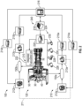
- FIG. 2 illustrates a hybrid electric propulsion system 100 (also referred to as hybrid gas turbine engine 100) including a gas turbine engine 120 operably coupled to an electrical power system 210 as part of a hybrid electric aircraft.
- One or more mechanical power transmissions 150 can be operably coupled between the gas turbine engine 120 and the electrical power system 210.
- the gas turbine engine 120 can be an embodiment of the gas turbine engine 20 of FIG.
- the electrical power system 210 can include a first electric motor 212A configured to augment rotational power of the low speed spool 30 and a second electric motor 212B configured to augment rotational power of the high speed spool 32. Although two electric motors 212A, 212B are depicted in FIG.
- the electrical power system 210 can also include a first electric generator 213A configured to convert rotational power of the low speed spool 30 to electric power and a second electric generator 213B configured to convert rotational power of the high speed spool 32 to electric power. Although two electric generators 213A, 213B are depicted in FIG. 2 , it will be understood that there may be only a single electric generator (e.g., only electric generator 213A) or additional electric generators (not depicted). In some embodiments, one or more of the electric motors 212A, 212B can be configured as a motor or a generator depending upon an operational mode or system configuration, and thus one or more of the electric generators 213A, 213B may be omitted.
- the mechanical power transmission 150A includes a gearbox operably coupled between the inner shaft 40 and a combination of the first electric motor 212A and first electric generator 213A.
- the mechanical power transmission 150B can include a gearbox operably coupled between the outer shaft 50 and a combination of the second electric motor 212B and second electric generator 213B.
- the mechanical power transmission 150A, 150B can include a clutch or other interfacing element(s).
- the electrical power system 210 can also include motor drive electronics 214A, 214B operable to condition current to the electric motors 212A, 212B (e.g., DC-to-AC converters).
- the electrical power system 210 can also include rectifier electronics 215A, 215B operable to condition current from the electric generators 213A, 213B (e.g., AC-to-DC converters).
- the motor drive electronics 214A, 214B and rectifier electronics 215A, 215B can interface with an energy storage management system 216 that further interfaces with an energy storage system 218.
- the energy storage management system 216 can be a bi-directional DC-DC converter that regulates voltages between energy storage system 218 and electronics 214A, 214B, 215A, 215B.
- the energy storage system 218 can include one or more energy storage devices, such as a battery, a super capacitor, an ultra capacitor, and the like.
- the energy storage management system 216 can facilitate various power transfers within the hybrid electric propulsion system 100. For example, power from the first electric generator 213A can be transferred 211 to the second electric motor 212B as a low speed spool 30 to high speed spool 32 power transfer. Other examples of power transfers may include a power transfer from the second electric generator 213B to the first electric motor 212A as a high speed spool 32 to low speed spool 30 power transfer.
- a power conditioning unit 220 and/or other components can be powered by the energy storage system 218.
- the power conditioning unit 220 can distribute electric power to support actuation and other functions of the gas turbine engine 120.
- the power conditioning unit 220 can power an integrated fuel control unit 222 to control fuel flow to the gas turbine engine 120.
- the power conditioning unit 220 can power a plurality of actuators 224, such as one or more of a low pressure compressor bleed valve actuator 226, a low pressure compressor vane actuator 228, a high pressure compressor vane actuator 230, an active clearance control actuator 232, and other such effectors.
- the low pressure compressor vane actuator 228 and/or the high pressure compressor vane actuator 230 can be omitted where active control of stator vanes 45, 55 of FIG.
- any effectors that can change a state of the gas turbine engine 120 and/or the electrical power system 210 may be referred to as hybrid electric system control effectors 240.
- Examples of the hybrid electric system control effectors 240 can include the electric motors 212A, 212B, electric generators 213A, 213B, integrated fuel control unit 222, actuators 224 and/or other elements (not depicted).
- variable vane actuators of the high speed spool 32 and/or the low speed spool 30 may be reduced and/or eliminated as the need for variable vanes may be reduced or eliminated.
- FIG. 3 is a schematic diagram of control signal paths 250 of the hybrid electric propulsion system 100 of FIG. 2 and is described with continued reference to FIGS. 1 and 2 .
- a controller 256 can interface with the motor drive electronics 214A, 214B, rectifier electronics 215A, 215B, energy storage management system 216, integrated fuel control unit 222, actuators 224, and/or other components (not depicted) of the hybrid electric propulsion system 100.
- the controller 256 can control and monitor for fault conditions of the gas turbine engine 120 and/or the electrical power system 210.
- the controller 256 can be integrally formed or otherwise in communication with a full authority digital engine control (FADEC) of the gas turbine engine 120.
- FADEC full authority digital engine control
- the controller 256 can include a processing system 260, a memory system 262, and an input/output interface 264.
- the controller 256 can also include various operational controls, such as a power transfer control 266 that controls the hybrid electric system control effectors 240 as further described herein.
- the processing system 260 can include any type or combination of central processing unit (CPU), including one or more of: a microprocessor, a digital signal processor (DSP), a microcontroller, an application specific integrated circuit (ASIC), a field programmable gate array (FPGA), or the like.
- the memory system 262 can store data and instructions that are executed by the processing system 260.
- the memory system 262 may include random access memory (RAM), read only memory (ROM), or other electronic, optical, magnetic, or any other computer readable medium onto which is stored data and algorithms in a non-transitory form.
- the input/output interface 264 is configured to collect sensor data from the one or more system sensors and interface with various components and subsystems, such as components of the motor drive electronics 214A, 214B, rectifier electronics 215A, 215B, energy storage management system 216, integrated fuel control unit 222, actuators 224, and/or other components (not depicted) of the hybrid electric propulsion system 100.
- the controller 256 provides a means for controlling the hybrid electric system control effectors 240 based on a power transfer control 266 that is dynamically updated during operation of the hybrid electric propulsion system 100.
- the means for controlling the hybrid electric system control effectors 240 can be otherwise subdivided, distributed, or combined with other control elements.
- the power transfer control 266 can apply control laws and access/update models to determine how to control and transfer power to and from the hybrid electric system control effectors 240. For example, sensed and/or derived parameters related to speed, flow rate, pressure ratios, temperature, thrust, and the like can be used to establish operational schedules and transition limits to maintain efficient operation of the gas turbine engine 120.
- a hybrid electric propulsion system 100 (also referred to as hybrid gas turbine engine 100) including a gas turbine engine 120 operably coupled to an electrical power system 210 as part of a hybrid electric aircraft in accordance with one non-limiting embodiment of the present disclosure is illustrated,
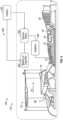
- the engine 120 has a power source 280 such as a battery, a super capacitor, an ultra capacitor or an equivalent thereof, which supplies power to a motor 282, which is connected to an engine accessory gearbox 284 that is operably coupled to the high speed spool 32 such that the motor 282, when operated will provide power assist to the high speed spool 32 via the accessory gearbox 284.
- the accessory gearbox will have at least one component (e.g., a gear train or other equivalent device) operably coupled to the high speed spool 32 and the motor 282 such that operation of the motor 282 will rotate the component which in turn will rotate the high speed spool 32.
- the power assist to the high speed spool 32 via the motor 282 will add enough stability to the high pressure compressor in order to allow re-starting without external power assist which may be provided by an auxiliary power unit (APU) or from an opposite engine (e.g., cross-bleed start).
- APU auxiliary power unit
- opposite engine e.g., cross-bleed start
- motor 282 may be motor 212B of the embodiment illustrated in FIG. 2 , which is configured to provide power assist to the high speed spool 32.
- motor 282 may be part of a different configuration or system configured to only provide power assist to the high speed spool 32 in order to expand an in-flight re-start envelope.
- motor 282 may be operatively coupled to the low speed spool 30 via accessory gearbox 284 in order to provide additional thrust to the engine 20.
- the system may be referred to a power assist system 286 that limits or avoids pilot or aircraft control intervention during an in-flight engine start process or re-start, in a "windmill" envelope where external power source such as APU or opposite engine power assist is not available or prohibited.
- the engine re-start may be autonomous (e.g., without pilot or aircraft control intervention) and the full authority digital engine control (FADEC) controls the power source and the engine.
- FADEC full authority digital engine control
- the engine re-start is autonomous (e.g., without pilot or aircraft control intervention) and the full authority digital engine control (FADEC) controls the power source and the engine.
- FADEC full authority digital engine control
- the power source 280 and the motor 282 of the power assist system 286 is under the full authority of the FADEC.
- the controller 256 can control and monitor for fault conditions of the gas turbine engine 120 and/or the electrical power system 210.
- the controller 256 can include a processing system 260, a memory system 262, and an input/output interface 264.
- the input/output interface 264 is configured to collect sensor data from the one or more system sensors and interface with various components and subsystems, such as components of the motor drive electronics 214A, 214B, rectifier electronics 215A, 215B, energy storage management system 216, integrated fuel control unit 222, actuators 224, and/or other components (not depicted) of the hybrid electric propulsion system 100.
- the controller 256 provides a means for controlling the hybrid electric system control effectors 240 based on a power transfer control 266 that is dynamically updated during operation of the hybrid electric propulsion system 100.
- the means for controlling the hybrid electric system control effectors 240 can be otherwise subdivided, distributed, or combined with other control elements.
- the power transfer control 266 can apply control laws and access/update models to determine how to control and transfer power to and from the hybrid electric system control effectors 240. For example, sensed and/or derived parameters related to speed, flow rate, pressure ratios, temperature, thrust, and the like can be used to establish operational schedules and transition limits to maintain efficient operation of the gas turbine engine 120. As such, the controller 256 is capable of determining an in-flight windmill re-start condition of the engine 120 by sensing the aforementioned parameters related to speed, flow rate, pressure ratios, temperature, thrust, fuel flow and the like.
- the controller 256 causes power to be supplied from a power source 280 to the electric motor 282 in order to augment rotational power of the high speed spool 32 or the low speed spool 30 during the detected in-flight windmill re-start condition.
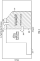
- FIG. 5 This "windmill" envelope is illustrated by the cross-hatched region in FIG. 5 , which shows the envelope where autonomous re-start is preferred or required.
- This region being referred to as an autonomous windmill envelope or re-start envelope 275, which is identified by arrow 275.
- FIG. 5 being a plot of altitude vs. airspeed for an in-flight re-start envelope.
- the unshaded area 277 may be referred to a region (altitude vs. airspeed) where auxiliary power unit (APU) or opposite engine power assist is available or allowed.
- APU auxiliary power unit
- a power source 280 such as a battery, a super capacitor, an ultra capacitor or an equivalent thereof and motor 282, and controller 256
- additional power is added to the high spool 32 of the engine 120 to provide an in-flight re-start in the autonomous windmill envelope.
- the autonomous windmill re-start envelope is expanded in the directions of arrows 288 and 290.
- This expanded boundary is illustrated by the grey areas 291 and 293 illustrated with the dotted line boundary in FIG. 5 .
- the grey regions 291 and 293 with the dotted line boundary shows that the re-start envelope 275 is expanded by internal battery and/or capacitor power assist.
- the controller 256 or (FADEC) of the gas turbine engine 120 will be configured to add enough power to the high speed spool 32 via motor 282 to provide compressor stability to the high pressure compressor 52 such that high pressure compressor bleed valves or are no longer needed.
Landscapes
- Engineering & Computer Science (AREA)
- Chemical & Material Sciences (AREA)
- Combustion & Propulsion (AREA)
- Mechanical Engineering (AREA)
- General Engineering & Computer Science (AREA)
- Aviation & Aerospace Engineering (AREA)
- Control Of Eletrric Generators (AREA)
Claims (11)
- Elektrisches Hybridantriebssystem (100), umfassend:einen Gasturbinenmotor (20; 120), umfassend eine Niedrigdrehzahlwelle (30) und eine Hochdrehzahlwelle (32), wobei die Niedrigdrehzahlwelle einen Niederdruckverdichter (44) und eine Niederdruckturbine (46) umfasst und die Hochdrehzahlwelle einen Hochdruckverdichter (52) und eine Hochdruckturbine (54) umfasst;einen Elektromotor (212A, 212B; 282), der dazu konfiguriert ist, die Drehleistung der Hochdrehzahlwelle (32) oder der Niedrigdrehzahlwelle (30) zu steigern; undeine Steuerung (256), die zu Folgendem betreibbar ist:Bestimmen, dass eine Gegenhilfskraftunterstützung des Motors verboten ist, mindestens teilweise basierend auf einer dem elektrischen Hybridantriebssystem zugeordneten Höhe und Geschwindigkeit relativ zur Luft;Erkennen eines Freidreh-Neustartzustands im Flug des Gasturbinenmotors, wobei der Freidreh-Neustartzustand im Flug des Gasturbinenmotors mindestens teilweise auf der Bestimmung basiert, dass eine Gegenhilfskraftunterstützung des Motors verboten ist; undVeranlassen, dass dem Elektromotor (212A, 212B; 282) Leistung von einer Leistungsquelle (280) zugeführt wird, um die Drehleistung der Hochdrehzahlwelle (32) oder der Niedrigdrehzahlwelle (30) während des erkannten Freidreh-Neustartzustands im Flug zu steigern;wobei die Steuerung (256) und der Elektromotor (212A, 212B; 282) dem Hochdruckverdichter (52) während des erkannten Freidreh-Neustartzustands im Flug Verdichterstabilität bereitstellen, sodass keine Hochdruckverdichter-Entlüftungsventile erforderlich sind.
- Elektrisches Hybridantriebssystem nach Anspruch 1, wobei die Steuerung (256) eine vollautorisierte digitale Motorregelung (FADEC) ist.
- Elektrisches Hybridantriebssystem nach Anspruch 1, wobei die Steuerung (256) eine vollautorisierte digitale Motorregelung (FADEC) ist, die volle Autorität über die Leistungsquelle (280) und den Elektromotor (212A, 212B; 282) aufweist.
- Elektrisches Hybridantriebssystem nach einem der vorhergehenden Ansprüche, wobei die Leistungsquelle (280) mindestens eines der Folgenden ist: eine Batterie; ein Superkondensator; und ein Ultrakondensator.
- Elektrisches Hybridantriebssystem nach einem der vorhergehenden Ansprüche, wobei der Elektromotor (212A, 212B; 282) mit einem Motoranbaugetriebe (284) verbunden ist, das mit der Hochdrehzahlwelle (32) wirkgekoppelt ist.
- Elektrisches Hybridantriebssystem nach einem der vorhergehenden Ansprüche, wobei der Elektromotor (212A, 212B; 282) dazu konfiguriert ist, die Drehleistung der Hochdrehzahlwelle (32) nur während des erkannten Freidreh-Neustartzustands im Flug des Gasturbinenmotors (20; 120) zu steigern.
- Verfahren zum Stabilisieren einer Verdichterstufe eines Gasturbinenmotors (20; 120) während eines Neustarts im Flug des Gasturbinenmotors, umfassend:Bereitstellen einer Hilfskraftunterstützung an eine Hochdrehzahlwelle (32) des Gasturbinenmotors (20) über einen Elektromotor (212A, 212B; 282), der während des Neustarts im Flug des Gasturbinenmotors mit der Hochdrehzahlwelle (32) wirkgekoppelt ist;Bestimmen, dass eine Gegenhilfskraftunterstützung des Motors verboten ist, mindestens teilweise basierend auf einer dem elektrischen Hybridantriebssystem zugeordneten Höhe und Geschwindigkeit relativ zur Luft;Erkennen eines Freidreh-Neustartzustands im Flug des Gasturbinenmotors, wobei der Freidreh-Neustartzustand im Flug des Gasturbinenmotors mindestens teilweise auf der Bestimmung basiert, dass eine Gegenhilfskraftunterstützung des Motors verboten ist;wobei durch eine Steuerung (256) veranlasst wird, dass dem Elektromotor (212A, 212B; 282) Leistung von einer Leistungsquelle (280) zugeführt wird; undwobei die Steuerung (256) und der Elektromotor (212A, 212B; 282) einem Hochdruckverdichter (52) der Hochdrehzahlwelle (32) während des Neustarts im Flug Verdichterstabilität bereitstellen, sodass keine Hochdruckverdichter-Entlüftungsventile für den Neustart im Flug erforderlich sind.
- Verfahren nach Anspruch 7, wobei der Neustart im Flug des Gasturbinenmotors (20) autonom erfolgt.
- Verfahren nach Anspruch 7 oder 8, wobei die Steuerung (256) volle Autorität über die Leistungsquelle (280) und den Elektromotor (212A, 212B; 282) aufweist.
- Verfahren nach Anspruch 7 oder 8, wobei die Steuerung (256) eine vollautorisierte digitale Motorregelung (FADEC) ist.
- Verfahren nach Anspruch 7 bis 10, wobei die Leistungsquelle (280) mindestens eines der Folgenden ist: eine Batterie; ein Superkondensator; und ein Ultrakondensator.
Applications Claiming Priority (1)
| Application Number | Priority Date | Filing Date | Title |
|---|---|---|---|
| US201962885773P | 2019-08-12 | 2019-08-12 |
Publications (2)
| Publication Number | Publication Date |
|---|---|
| EP3789603A1 EP3789603A1 (de) | 2021-03-10 |
| EP3789603B1 true EP3789603B1 (de) | 2025-01-08 |
Family
ID=72050773
Family Applications (1)
| Application Number | Title | Priority Date | Filing Date |
|---|---|---|---|
| EP20190770.6A Active EP3789603B1 (de) | 2019-08-12 | 2020-08-12 | Elektrische hilfskraftunterstützung für motorneustart im flug |
Country Status (2)
| Country | Link |
|---|---|
| US (1) | US11821369B2 (de) |
| EP (1) | EP3789603B1 (de) |
Families Citing this family (45)
| Publication number | Priority date | Publication date | Assignee | Title |
|---|---|---|---|---|
| US20210108569A1 (en) * | 2019-10-15 | 2021-04-15 | General Electric Company | Gas turbine engine with clutch assembly |
| US11215117B2 (en) * | 2019-11-08 | 2022-01-04 | Raytheon Technologies Corporation | Gas turbine engine having electric motor applying power to the high pressure spool shaft and method for operating same |
| US20220220900A1 (en) * | 2021-01-14 | 2022-07-14 | The Boeing Company | Automated Initiation of Starter Motor Operation for Starting an Aircraft Engine |
| US11821372B2 (en) | 2021-06-11 | 2023-11-21 | Rtx Corporation | Hybrid electric engine with electric tip clearance mechanism |
| EP4173957A1 (de) * | 2021-10-29 | 2023-05-03 | Raytheon Technologies Corporation | Energiemanagement bei ausfall eines triebwerks im sinkflug für ein hybrid-elektrisches antriebssystem |
| EP4174298B1 (de) * | 2021-10-29 | 2024-08-28 | RTX Corporation | Hybridelektrische motorabstiegsverwaltung für einen einzelmotor |
| US12202616B2 (en) | 2021-11-04 | 2025-01-21 | General Electric Company | Relight of a propulsion system with a fuel cell |
| CN114194380B (zh) * | 2021-11-24 | 2024-01-05 | 北京机电工程研究所 | 螺旋桨与发动机空中配合起动方法及装置 |
| GB202118041D0 (en) * | 2021-12-14 | 2022-01-26 | Rolls Royce Plc | Restarting a gas turbine engine |
| US12123361B2 (en) | 2022-01-04 | 2024-10-22 | General Electric Company | Systems and methods for providing output products to a combustion chamber of a gas turbine engine |
| US12037952B2 (en) | 2022-01-04 | 2024-07-16 | General Electric Company | Systems and methods for providing output products to a combustion chamber of a gas turbine engine |
| US11933216B2 (en) | 2022-01-04 | 2024-03-19 | General Electric Company | Systems and methods for providing output products to a combustion chamber of a gas turbine engine |
| US11794912B2 (en) | 2022-01-04 | 2023-10-24 | General Electric Company | Systems and methods for reducing emissions with a fuel cell |
| US11719441B2 (en) | 2022-01-04 | 2023-08-08 | General Electric Company | Systems and methods for providing output products to a combustion chamber of a gas turbine engine |
| US11970282B2 (en) | 2022-01-05 | 2024-04-30 | General Electric Company | Aircraft thrust management with a fuel cell |
| US12034298B2 (en) | 2022-01-10 | 2024-07-09 | General Electric Company | Power source for an aircraft |
| US12037124B2 (en) | 2022-01-21 | 2024-07-16 | General Electric Company | Systems and method of operating a fuel cell assembly |
| US11804607B2 (en) | 2022-01-21 | 2023-10-31 | General Electric Company | Cooling of a fuel cell assembly |
| US12351329B2 (en) | 2022-01-21 | 2025-07-08 | General Electric Company | Systems and method of operating a fuel cell assembly |
| US12074350B2 (en) | 2022-01-21 | 2024-08-27 | General Electric Company | Solid oxide fuel cell assembly |
| US12573647B2 (en) | 2022-01-21 | 2026-03-10 | General Electric Company | Solid oxide fuel cell assembly |
| US12170390B2 (en) | 2022-02-21 | 2024-12-17 | General Electric Company | Systems and method of operating a fuel cell assembly, a gas turbine engine, or both |
| US11967743B2 (en) | 2022-02-21 | 2024-04-23 | General Electric Company | Modular fuel cell assembly |
| US12129789B2 (en) | 2022-02-21 | 2024-10-29 | General Electric Company | Systems and method of operating a fuel cell assembly, a gas turbine engine, or both |
| US12025061B2 (en) | 2022-04-04 | 2024-07-02 | General Electric Company | Gas turbine engine with fuel cell assembly |
| US12412914B2 (en) | 2022-05-16 | 2025-09-09 | General Electric Company | Environmental control system having a fuel cell assembly |
| US12428164B2 (en) | 2022-05-16 | 2025-09-30 | General Electric Company | Environmental control system having a fuel cell assembly |
| US12043406B2 (en) | 2022-05-27 | 2024-07-23 | General Electric Company | Method of operating a fuel cell assembly for an aircraft |
| US12253030B2 (en) | 2022-07-01 | 2025-03-18 | Rtx Corporation | In-flight engine re-start |
| US11817700B1 (en) | 2022-07-20 | 2023-11-14 | General Electric Company | Decentralized electrical power allocation system |
| US12301002B2 (en) | 2022-08-26 | 2025-05-13 | General Electric Company | Power dispatch control system for multiple power generation sources |
| US12567595B2 (en) | 2022-11-10 | 2026-03-03 | General Electric Company | Gas turbine combustion section having an integrated fuel cell assembly |
| US11859820B1 (en) | 2022-11-10 | 2024-01-02 | General Electric Company | Gas turbine combustion section having an integrated fuel cell assembly |
| US12240613B2 (en) | 2022-11-10 | 2025-03-04 | General Electric Company | Gas turbine combustion section having an integrated fuel cell assembly |
| US12078350B2 (en) | 2022-11-10 | 2024-09-03 | General Electric Company | Gas turbine combustion section having an integrated fuel cell assembly |
| US11923586B1 (en) | 2022-11-10 | 2024-03-05 | General Electric Company | Gas turbine combustion section having an integrated fuel cell assembly |
| CN118532266A (zh) | 2023-02-23 | 2024-08-23 | 通用电气公司 | 燃气涡轮发动机和燃料电池组件 |
| CN118532265A (zh) | 2023-02-23 | 2024-08-23 | 通用电气公司 | 燃气涡轮发动机和燃料电池组件 |
| CN118532263A (zh) | 2023-02-23 | 2024-08-23 | 通用电气公司 | 燃气涡轮发动机和燃料电池组件 |
| FR3151056B1 (fr) | 2023-07-11 | 2026-03-13 | Safran Aircraft Engines | Turbomachine d’aéronef et son procédé de redémarrage en vol |
| US12571350B2 (en) | 2023-07-28 | 2026-03-10 | Rolls-Royce Corporation | Multi-modal gas-turbine engine starting |
| US12180894B1 (en) | 2023-07-28 | 2024-12-31 | Rolls-Royce Corporation | Electric starter verification during gas-turbine engine barring |
| US12270333B2 (en) * | 2023-08-28 | 2025-04-08 | Rtx Corporation | Partial exhaust gas condensation with inverse Brayton control |
| EP4575209A1 (de) * | 2023-12-20 | 2025-06-25 | Rolls-Royce Corporation | Überprüfung eines elektrischen starters während des drehens eines gasturbinenmotors |
| US12546259B2 (en) | 2024-03-08 | 2026-02-10 | General Electric Company | Systems and methods for integrating use of starter on the low pressure spool of a turbine engine |
Citations (2)
| Publication number | Priority date | Publication date | Assignee | Title |
|---|---|---|---|---|
| FR3056558A1 (fr) * | 2016-09-26 | 2018-03-30 | Safran | Procede d'optimisation de l'operabilite de la motorisation d'un aeronef |
| EP3663535A1 (de) * | 2018-12-03 | 2020-06-10 | Rolls-Royce plc | Verfahren und vorrichtung zur steuerung von mindestens einem teil eines anlass- oder neuzündungsprozesses eines gasturbinentriebwerks |
Family Cites Families (17)
| Publication number | Priority date | Publication date | Assignee | Title |
|---|---|---|---|---|
| US5125597A (en) * | 1990-06-01 | 1992-06-30 | General Electric Company | Gas turbine engine powered aircraft environmental control system and boundary layer bleed with energy recovery system |
| GB9910393D0 (en) * | 1999-05-05 | 1999-07-07 | Lucas Ind Plc | Electrical generator,an aero-engine including such a generator and an aircraft including such a generator |
| US7210653B2 (en) | 2002-10-22 | 2007-05-01 | The Boeing Company | Electric-based secondary power system architectures for aircraft |
| US7513119B2 (en) * | 2005-02-03 | 2009-04-07 | The Boeing Company | Systems and methods for starting aircraft engines |
| US7805947B2 (en) * | 2005-05-19 | 2010-10-05 | Djamal Moulebhar | Aircraft with disengageable engine and auxiliary power unit components |
| US7802757B2 (en) | 2005-11-09 | 2010-09-28 | Pratt & Whitney Canada Corp. | Method and system for taxiing an aircraft |
| US8218341B2 (en) | 2008-09-26 | 2012-07-10 | General Electric Company | Integrated aircraft power conditioning unit |
| US20100108806A1 (en) | 2008-10-08 | 2010-05-06 | Searete Llc, A Limited Liability Corporation Of The State Of Delaware | Hybrid propulsive engine including at least one independently rotatable propeller/fan |
| US9051881B2 (en) * | 2010-12-28 | 2015-06-09 | Rolls-Royce Corporation | Electrical power generation and windmill starting for turbine engine and aircraft |
| US10094293B2 (en) | 2014-08-22 | 2018-10-09 | Pratt & Whitney Canada Corp. | In flight restart system and method for free turbine engine |
| GB201420444D0 (en) * | 2014-11-18 | 2014-12-31 | Rolls Royce Plc | A method of starting a gas turbine engine |
| US9982607B2 (en) * | 2015-07-20 | 2018-05-29 | Rolls-Royce North American Technologies, Inc. | Shaft failure detection using passive control methods |
| US10724443B2 (en) * | 2016-05-24 | 2020-07-28 | General Electric Company | Turbine engine and method of operating |
| US10641179B2 (en) * | 2016-11-07 | 2020-05-05 | General Electric Company | System and method for starting gas turbine engines |
| US10676199B2 (en) * | 2017-06-12 | 2020-06-09 | General Electric Company | Propulsion system for an aircraft |
| GB201803039D0 (en) * | 2018-02-26 | 2018-04-11 | Rolls Royce Plc | Apparatus for a gas turbine engine |
| GB201819696D0 (en) * | 2018-12-03 | 2019-01-16 | Rolls Royce Plc | Methods and apparatus for controlling at least part of a start-up or re-light process of a gas turbine engine |
-
2020
- 2020-08-12 US US16/991,143 patent/US11821369B2/en active Active
- 2020-08-12 EP EP20190770.6A patent/EP3789603B1/de active Active
Patent Citations (2)
| Publication number | Priority date | Publication date | Assignee | Title |
|---|---|---|---|---|
| FR3056558A1 (fr) * | 2016-09-26 | 2018-03-30 | Safran | Procede d'optimisation de l'operabilite de la motorisation d'un aeronef |
| EP3663535A1 (de) * | 2018-12-03 | 2020-06-10 | Rolls-Royce plc | Verfahren und vorrichtung zur steuerung von mindestens einem teil eines anlass- oder neuzündungsprozesses eines gasturbinentriebwerks |
Also Published As
| Publication number | Publication date |
|---|---|
| US20210115857A1 (en) | 2021-04-22 |
| EP3789603A1 (de) | 2021-03-10 |
| US11821369B2 (en) | 2023-11-21 |
Similar Documents
| Publication | Publication Date | Title |
|---|---|---|
| EP3789603B1 (de) | Elektrische hilfskraftunterstützung für motorneustart im flug | |
| EP3693571B1 (de) | Transiente betriebssteuerung eines hybrid-gasturbinenmotors | |
| EP3779147B1 (de) | Rotordynamikausgleich unter verwendung von elektrischem hilfsantrieb | |
| US12123344B2 (en) | Engine and secondary power unit integrated operation | |
| EP4352349B1 (de) | Ölzirkulationssystem für hybride elektrische motoren | |
| US11821372B2 (en) | Hybrid electric engine with electric tip clearance mechanism | |
| EP3767090B2 (de) | Steuerung der betriebsfähigkeit eines kompressors für einen hybriden elektrischen antrieb | |
| EP4102044A2 (de) | Elektrische hybridmotorleistungsverteilung | |
| EP4112909A1 (de) | Hybridelektrische turbine mit variabler fläche | |
| US20240003300A1 (en) | In-flight engine re-start | |
| EP3772579B1 (de) | Wellenkupplungssystem für gasturbinenmotor | |
| EP3767092B1 (de) | Modulierter brennkammer-bypass für hybridleerlauf | |
| US20220397067A1 (en) | Hybrid electric idle transition for aircraft | |
| US11557995B2 (en) | Aircraft engine power-assist start stability control | |
| EP3779150B1 (de) | Verbesserung bei der materialermüdung für hybride antriebssysteme | |
| US11649763B1 (en) | Rating control architecture and method for hybrid electric engine |
Legal Events
| Date | Code | Title | Description |
|---|---|---|---|
| PUAI | Public reference made under article 153(3) epc to a published international application that has entered the european phase |
Free format text: ORIGINAL CODE: 0009012 |
|
| STAA | Information on the status of an ep patent application or granted ep patent |
Free format text: STATUS: THE APPLICATION HAS BEEN PUBLISHED |
|
| AK | Designated contracting states |
Kind code of ref document: A1 Designated state(s): AL AT BE BG CH CY CZ DE DK EE ES FI FR GB GR HR HU IE IS IT LI LT LU LV MC MK MT NL NO PL PT RO RS SE SI SK SM TR |
|
| AX | Request for extension of the european patent |
Extension state: BA ME |
|
| STAA | Information on the status of an ep patent application or granted ep patent |
Free format text: STATUS: REQUEST FOR EXAMINATION WAS MADE |
|
| 17P | Request for examination filed |
Effective date: 20210910 |
|
| RBV | Designated contracting states (corrected) |
Designated state(s): AL AT BE BG CH CY CZ DE DK EE ES FI FR GB GR HR HU IE IS IT LI LT LU LV MC MK MT NL NO PL PT RO RS SE SI SK SM TR |
|
| STAA | Information on the status of an ep patent application or granted ep patent |
Free format text: STATUS: EXAMINATION IS IN PROGRESS |
|
| 17Q | First examination report despatched |
Effective date: 20220831 |
|
| RAP3 | Party data changed (applicant data changed or rights of an application transferred) |
Owner name: RTX CORPORATION |
|
| GRAP | Despatch of communication of intention to grant a patent |
Free format text: ORIGINAL CODE: EPIDOSNIGR1 |
|
| STAA | Information on the status of an ep patent application or granted ep patent |
Free format text: STATUS: GRANT OF PATENT IS INTENDED |
|
| INTG | Intention to grant announced |
Effective date: 20240801 |
|
| GRAS | Grant fee paid |
Free format text: ORIGINAL CODE: EPIDOSNIGR3 |
|
| GRAA | (expected) grant |
Free format text: ORIGINAL CODE: 0009210 |
|
| STAA | Information on the status of an ep patent application or granted ep patent |
Free format text: STATUS: THE PATENT HAS BEEN GRANTED |
|
| AK | Designated contracting states |
Kind code of ref document: B1 Designated state(s): AL AT BE BG CH CY CZ DE DK EE ES FI FR GB GR HR HU IE IS IT LI LT LU LV MC MK MT NL NO PL PT RO RS SE SI SK SM TR |
|
| REG | Reference to a national code |
Ref country code: GB Ref legal event code: FG4D |
|
| REG | Reference to a national code |
Ref country code: CH Ref legal event code: EP |
|
| REG | Reference to a national code |
Ref country code: DE Ref legal event code: R096 Ref document number: 602020044423 Country of ref document: DE |
|
| REG | Reference to a national code |
Ref country code: IE Ref legal event code: FG4D |
|
| REG | Reference to a national code |
Ref country code: LT Ref legal event code: MG9D |
|
| REG | Reference to a national code |
Ref country code: NL Ref legal event code: MP Effective date: 20250108 |
|
| REG | Reference to a national code |
Ref country code: AT Ref legal event code: MK05 Ref document number: 1758470 Country of ref document: AT Kind code of ref document: T Effective date: 20250108 |
|
| PG25 | Lapsed in a contracting state [announced via postgrant information from national office to epo] |
Ref country code: NL Free format text: LAPSE BECAUSE OF FAILURE TO SUBMIT A TRANSLATION OF THE DESCRIPTION OR TO PAY THE FEE WITHIN THE PRESCRIBED TIME-LIMIT Effective date: 20250108 |
|
| PG25 | Lapsed in a contracting state [announced via postgrant information from national office to epo] |
Ref country code: RS Free format text: LAPSE BECAUSE OF FAILURE TO SUBMIT A TRANSLATION OF THE DESCRIPTION OR TO PAY THE FEE WITHIN THE PRESCRIBED TIME-LIMIT Effective date: 20250408 |
|
| PG25 | Lapsed in a contracting state [announced via postgrant information from national office to epo] |
Ref country code: FI Free format text: LAPSE BECAUSE OF FAILURE TO SUBMIT A TRANSLATION OF THE DESCRIPTION OR TO PAY THE FEE WITHIN THE PRESCRIBED TIME-LIMIT Effective date: 20250108 |
|
| PG25 | Lapsed in a contracting state [announced via postgrant information from national office to epo] |
Ref country code: PL Free format text: LAPSE BECAUSE OF FAILURE TO SUBMIT A TRANSLATION OF THE DESCRIPTION OR TO PAY THE FEE WITHIN THE PRESCRIBED TIME-LIMIT Effective date: 20250108 |
|
| PG25 | Lapsed in a contracting state [announced via postgrant information from national office to epo] |
Ref country code: ES Free format text: LAPSE BECAUSE OF FAILURE TO SUBMIT A TRANSLATION OF THE DESCRIPTION OR TO PAY THE FEE WITHIN THE PRESCRIBED TIME-LIMIT Effective date: 20250108 |
|
| PG25 | Lapsed in a contracting state [announced via postgrant information from national office to epo] |
Ref country code: IS Free format text: LAPSE BECAUSE OF FAILURE TO SUBMIT A TRANSLATION OF THE DESCRIPTION OR TO PAY THE FEE WITHIN THE PRESCRIBED TIME-LIMIT Effective date: 20250508 Ref country code: NO Free format text: LAPSE BECAUSE OF FAILURE TO SUBMIT A TRANSLATION OF THE DESCRIPTION OR TO PAY THE FEE WITHIN THE PRESCRIBED TIME-LIMIT Effective date: 20250408 |
|
| PG25 | Lapsed in a contracting state [announced via postgrant information from national office to epo] |
Ref country code: HR Free format text: LAPSE BECAUSE OF FAILURE TO SUBMIT A TRANSLATION OF THE DESCRIPTION OR TO PAY THE FEE WITHIN THE PRESCRIBED TIME-LIMIT Effective date: 20250108 |
|
| PG25 | Lapsed in a contracting state [announced via postgrant information from national office to epo] |
Ref country code: PT Free format text: LAPSE BECAUSE OF FAILURE TO SUBMIT A TRANSLATION OF THE DESCRIPTION OR TO PAY THE FEE WITHIN THE PRESCRIBED TIME-LIMIT Effective date: 20250508 Ref country code: LV Free format text: LAPSE BECAUSE OF FAILURE TO SUBMIT A TRANSLATION OF THE DESCRIPTION OR TO PAY THE FEE WITHIN THE PRESCRIBED TIME-LIMIT Effective date: 20250108 |
|
| PG25 | Lapsed in a contracting state [announced via postgrant information from national office to epo] |
Ref country code: GR Free format text: LAPSE BECAUSE OF FAILURE TO SUBMIT A TRANSLATION OF THE DESCRIPTION OR TO PAY THE FEE WITHIN THE PRESCRIBED TIME-LIMIT Effective date: 20250409 Ref country code: BG Free format text: LAPSE BECAUSE OF FAILURE TO SUBMIT A TRANSLATION OF THE DESCRIPTION OR TO PAY THE FEE WITHIN THE PRESCRIBED TIME-LIMIT Effective date: 20250108 |
|
| PG25 | Lapsed in a contracting state [announced via postgrant information from national office to epo] |
Ref country code: AT Free format text: LAPSE BECAUSE OF FAILURE TO SUBMIT A TRANSLATION OF THE DESCRIPTION OR TO PAY THE FEE WITHIN THE PRESCRIBED TIME-LIMIT Effective date: 20250108 |
|
| PG25 | Lapsed in a contracting state [announced via postgrant information from national office to epo] |
Ref country code: SE Free format text: LAPSE BECAUSE OF FAILURE TO SUBMIT A TRANSLATION OF THE DESCRIPTION OR TO PAY THE FEE WITHIN THE PRESCRIBED TIME-LIMIT Effective date: 20250108 |
|
| PG25 | Lapsed in a contracting state [announced via postgrant information from national office to epo] |
Ref country code: SM Free format text: LAPSE BECAUSE OF FAILURE TO SUBMIT A TRANSLATION OF THE DESCRIPTION OR TO PAY THE FEE WITHIN THE PRESCRIBED TIME-LIMIT Effective date: 20250108 |
|
| REG | Reference to a national code |
Ref country code: DE Ref legal event code: R097 Ref document number: 602020044423 Country of ref document: DE |
|
| PG25 | Lapsed in a contracting state [announced via postgrant information from national office to epo] |
Ref country code: DK Free format text: LAPSE BECAUSE OF FAILURE TO SUBMIT A TRANSLATION OF THE DESCRIPTION OR TO PAY THE FEE WITHIN THE PRESCRIBED TIME-LIMIT Effective date: 20250108 |
|
| PGFP | Annual fee paid to national office [announced via postgrant information from national office to epo] |
Ref country code: DE Payment date: 20250724 Year of fee payment: 6 |
|
| PGFP | Annual fee paid to national office [announced via postgrant information from national office to epo] |
Ref country code: GB Payment date: 20250724 Year of fee payment: 6 |
|
| PGFP | Annual fee paid to national office [announced via postgrant information from national office to epo] |
Ref country code: FR Payment date: 20250723 Year of fee payment: 6 |
|
| PG25 | Lapsed in a contracting state [announced via postgrant information from national office to epo] |
Ref country code: CZ Free format text: LAPSE BECAUSE OF FAILURE TO SUBMIT A TRANSLATION OF THE DESCRIPTION OR TO PAY THE FEE WITHIN THE PRESCRIBED TIME-LIMIT Effective date: 20250108 Ref country code: EE Free format text: LAPSE BECAUSE OF FAILURE TO SUBMIT A TRANSLATION OF THE DESCRIPTION OR TO PAY THE FEE WITHIN THE PRESCRIBED TIME-LIMIT Effective date: 20250108 |
|
| PG25 | Lapsed in a contracting state [announced via postgrant information from national office to epo] |
Ref country code: RO Free format text: LAPSE BECAUSE OF FAILURE TO SUBMIT A TRANSLATION OF THE DESCRIPTION OR TO PAY THE FEE WITHIN THE PRESCRIBED TIME-LIMIT Effective date: 20250108 |
|
| PG25 | Lapsed in a contracting state [announced via postgrant information from national office to epo] |
Ref country code: SK Free format text: LAPSE BECAUSE OF FAILURE TO SUBMIT A TRANSLATION OF THE DESCRIPTION OR TO PAY THE FEE WITHIN THE PRESCRIBED TIME-LIMIT Effective date: 20250108 |
|
| PLBE | No opposition filed within time limit |
Free format text: ORIGINAL CODE: 0009261 |
|
| STAA | Information on the status of an ep patent application or granted ep patent |
Free format text: STATUS: NO OPPOSITION FILED WITHIN TIME LIMIT |
|
| REG | Reference to a national code |
Ref country code: CH Ref legal event code: L10 Free format text: ST27 STATUS EVENT CODE: U-0-0-L10-L00 (AS PROVIDED BY THE NATIONAL OFFICE) Effective date: 20251119 |
|
| 26N | No opposition filed |
Effective date: 20251009 |
|
| PG25 | Lapsed in a contracting state [announced via postgrant information from national office to epo] |
Ref country code: IT Free format text: LAPSE BECAUSE OF FAILURE TO SUBMIT A TRANSLATION OF THE DESCRIPTION OR TO PAY THE FEE WITHIN THE PRESCRIBED TIME-LIMIT Effective date: 20250108 |
|
| REG | Reference to a national code |
Ref country code: CH Ref legal event code: H13 Free format text: ST27 STATUS EVENT CODE: U-0-0-H10-H13 (AS PROVIDED BY THE NATIONAL OFFICE) Effective date: 20260324 |
|
| PG25 | Lapsed in a contracting state [announced via postgrant information from national office to epo] |
Ref country code: MC Free format text: LAPSE BECAUSE OF FAILURE TO SUBMIT A TRANSLATION OF THE DESCRIPTION OR TO PAY THE FEE WITHIN THE PRESCRIBED TIME-LIMIT Effective date: 20250108 |
|
| PG25 | Lapsed in a contracting state [announced via postgrant information from national office to epo] |
Ref country code: LU Free format text: LAPSE BECAUSE OF NON-PAYMENT OF DUE FEES Effective date: 20250812 |
|
| PG25 | Lapsed in a contracting state [announced via postgrant information from national office to epo] |
Ref country code: CH Free format text: LAPSE BECAUSE OF NON-PAYMENT OF DUE FEES Effective date: 20250831 |