EP4112909A1 - Hybridelektrische turbine mit variabler fläche - Google Patents
Hybridelektrische turbine mit variabler fläche Download PDFInfo
- Publication number
- EP4112909A1 EP4112909A1 EP22181383.5A EP22181383A EP4112909A1 EP 4112909 A1 EP4112909 A1 EP 4112909A1 EP 22181383 A EP22181383 A EP 22181383A EP 4112909 A1 EP4112909 A1 EP 4112909A1
- Authority
- EP
- European Patent Office
- Prior art keywords
- turbine
- variable area
- engine
- hybrid electric
- control system
- Prior art date
- Legal status (The legal status is an assumption and is not a legal conclusion. Google has not performed a legal analysis and makes no representation as to the accuracy of the status listed.)
- Pending
Links
- 230000005611 electricity Effects 0.000 claims abstract description 20
- 238000000034 method Methods 0.000 claims description 20
- 239000000446 fuel Substances 0.000 claims description 16
- 239000003990 capacitor Substances 0.000 claims description 6
- 230000007423 decrease Effects 0.000 claims description 3
- 238000004146 energy storage Methods 0.000 description 10
- 238000012546 transfer Methods 0.000 description 9
- 239000012636 effector Substances 0.000 description 8
- 230000000670 limiting effect Effects 0.000 description 8
- 238000007726 management method Methods 0.000 description 5
- 230000007246 mechanism Effects 0.000 description 5
- 230000005540 biological transmission Effects 0.000 description 4
- 238000004891 communication Methods 0.000 description 4
- 230000003750 conditioning effect Effects 0.000 description 4
- 238000010586 diagram Methods 0.000 description 4
- 238000012545 processing Methods 0.000 description 4
- 230000003068 static effect Effects 0.000 description 4
- 230000008859 change Effects 0.000 description 2
- 230000036961 partial effect Effects 0.000 description 2
- 230000009467 reduction Effects 0.000 description 2
- 230000006835 compression Effects 0.000 description 1
- 238000007906 compression Methods 0.000 description 1
- 238000012937 correction Methods 0.000 description 1
- 230000003247 decreasing effect Effects 0.000 description 1
- 230000006870 function Effects 0.000 description 1
- 239000000463 material Substances 0.000 description 1
- 238000005259 measurement Methods 0.000 description 1
- 238000012986 modification Methods 0.000 description 1
- 230000004048 modification Effects 0.000 description 1
- 230000003287 optical effect Effects 0.000 description 1
- 238000010248 power generation Methods 0.000 description 1
- 230000008569 process Effects 0.000 description 1
- 230000002829 reductive effect Effects 0.000 description 1
- 230000004044 response Effects 0.000 description 1
- 230000007704 transition Effects 0.000 description 1
Images


Classifications
-
- F—MECHANICAL ENGINEERING; LIGHTING; HEATING; WEAPONS; BLASTING
- F02—COMBUSTION ENGINES; HOT-GAS OR COMBUSTION-PRODUCT ENGINE PLANTS
- F02C—GAS-TURBINE PLANTS; AIR INTAKES FOR JET-PROPULSION PLANTS; CONTROLLING FUEL SUPPLY IN AIR-BREATHING JET-PROPULSION PLANTS
- F02C9/00—Controlling gas-turbine plants; Controlling fuel supply in air- breathing jet-propulsion plants
- F02C9/16—Control of working fluid flow
- F02C9/20—Control of working fluid flow by throttling; by adjusting vanes
- F02C9/22—Control of working fluid flow by throttling; by adjusting vanes by adjusting turbine vanes
-
- F—MECHANICAL ENGINEERING; LIGHTING; HEATING; WEAPONS; BLASTING
- F01—MACHINES OR ENGINES IN GENERAL; ENGINE PLANTS IN GENERAL; STEAM ENGINES
- F01D—NON-POSITIVE DISPLACEMENT MACHINES OR ENGINES, e.g. STEAM TURBINES
- F01D17/00—Regulating or controlling by varying flow
- F01D17/10—Final actuators
- F01D17/12—Final actuators arranged in stator parts
- F01D17/14—Final actuators arranged in stator parts varying effective cross-sectional area of nozzles or guide conduits
- F01D17/16—Final actuators arranged in stator parts varying effective cross-sectional area of nozzles or guide conduits by means of nozzle vanes
-
- F—MECHANICAL ENGINEERING; LIGHTING; HEATING; WEAPONS; BLASTING
- F01—MACHINES OR ENGINES IN GENERAL; ENGINE PLANTS IN GENERAL; STEAM ENGINES
- F01D—NON-POSITIVE DISPLACEMENT MACHINES OR ENGINES, e.g. STEAM TURBINES
- F01D15/00—Adaptations of machines or engines for special use; Combinations of engines with devices driven thereby
- F01D15/10—Adaptations for driving, or combinations with, electric generators
-
- F—MECHANICAL ENGINEERING; LIGHTING; HEATING; WEAPONS; BLASTING
- F01—MACHINES OR ENGINES IN GENERAL; ENGINE PLANTS IN GENERAL; STEAM ENGINES
- F01D—NON-POSITIVE DISPLACEMENT MACHINES OR ENGINES, e.g. STEAM TURBINES
- F01D17/00—Regulating or controlling by varying flow
- F01D17/10—Final actuators
- F01D17/12—Final actuators arranged in stator parts
- F01D17/14—Final actuators arranged in stator parts varying effective cross-sectional area of nozzles or guide conduits
- F01D17/16—Final actuators arranged in stator parts varying effective cross-sectional area of nozzles or guide conduits by means of nozzle vanes
- F01D17/162—Final actuators arranged in stator parts varying effective cross-sectional area of nozzles or guide conduits by means of nozzle vanes for axial flow, i.e. the vanes turning around axes which are essentially perpendicular to the rotor centre line
-
- F—MECHANICAL ENGINEERING; LIGHTING; HEATING; WEAPONS; BLASTING
- F01—MACHINES OR ENGINES IN GENERAL; ENGINE PLANTS IN GENERAL; STEAM ENGINES
- F01D—NON-POSITIVE DISPLACEMENT MACHINES OR ENGINES, e.g. STEAM TURBINES
- F01D17/00—Regulating or controlling by varying flow
- F01D17/20—Devices dealing with sensing elements or final actuators or transmitting means between them, e.g. power-assisted
- F01D17/22—Devices dealing with sensing elements or final actuators or transmitting means between them, e.g. power-assisted the operation or power assistance being predominantly non-mechanical
- F01D17/24—Devices dealing with sensing elements or final actuators or transmitting means between them, e.g. power-assisted the operation or power assistance being predominantly non-mechanical electrical
-
- F—MECHANICAL ENGINEERING; LIGHTING; HEATING; WEAPONS; BLASTING
- F05—INDEXING SCHEMES RELATING TO ENGINES OR PUMPS IN VARIOUS SUBCLASSES OF CLASSES F01-F04
- F05D—INDEXING SCHEME FOR ASPECTS RELATING TO NON-POSITIVE-DISPLACEMENT MACHINES OR ENGINES, GAS-TURBINES OR JET-PROPULSION PLANTS
- F05D2220/00—Application
- F05D2220/30—Application in turbines
- F05D2220/32—Application in turbines in gas turbines
- F05D2220/323—Application in turbines in gas turbines for aircraft propulsion, e.g. jet engines
-
- F—MECHANICAL ENGINEERING; LIGHTING; HEATING; WEAPONS; BLASTING
- F05—INDEXING SCHEMES RELATING TO ENGINES OR PUMPS IN VARIOUS SUBCLASSES OF CLASSES F01-F04
- F05D—INDEXING SCHEME FOR ASPECTS RELATING TO NON-POSITIVE-DISPLACEMENT MACHINES OR ENGINES, GAS-TURBINES OR JET-PROPULSION PLANTS
- F05D2220/00—Application
- F05D2220/70—Application in combination with
- F05D2220/76—Application in combination with an electrical generator
-
- F—MECHANICAL ENGINEERING; LIGHTING; HEATING; WEAPONS; BLASTING
- F05—INDEXING SCHEMES RELATING TO ENGINES OR PUMPS IN VARIOUS SUBCLASSES OF CLASSES F01-F04
- F05D—INDEXING SCHEME FOR ASPECTS RELATING TO NON-POSITIVE-DISPLACEMENT MACHINES OR ENGINES, GAS-TURBINES OR JET-PROPULSION PLANTS
- F05D2250/00—Geometry
- F05D2250/90—Variable geometry
-
- F—MECHANICAL ENGINEERING; LIGHTING; HEATING; WEAPONS; BLASTING
- F05—INDEXING SCHEMES RELATING TO ENGINES OR PUMPS IN VARIOUS SUBCLASSES OF CLASSES F01-F04
- F05D—INDEXING SCHEME FOR ASPECTS RELATING TO NON-POSITIVE-DISPLACEMENT MACHINES OR ENGINES, GAS-TURBINES OR JET-PROPULSION PLANTS
- F05D2260/00—Function
- F05D2260/70—Adjusting of angle of incidence or attack of rotating blades
- F05D2260/76—Adjusting of angle of incidence or attack of rotating blades the adjusting mechanism using auxiliary power sources
-
- F—MECHANICAL ENGINEERING; LIGHTING; HEATING; WEAPONS; BLASTING
- F05—INDEXING SCHEMES RELATING TO ENGINES OR PUMPS IN VARIOUS SUBCLASSES OF CLASSES F01-F04
- F05D—INDEXING SCHEME FOR ASPECTS RELATING TO NON-POSITIVE-DISPLACEMENT MACHINES OR ENGINES, GAS-TURBINES OR JET-PROPULSION PLANTS
- F05D2270/00—Control
- F05D2270/60—Control system actuates means
- F05D2270/62—Electrical actuators
Definitions
- the subject matter disclosed herein relates generally to hybrid electric engines and, more particularly, to a method and an apparatus for control of a variable area turbine with a hybrid electric engine.
- a hybrid electric engine including a gas turbine engine including a low speed spool, a high speed spool a fan section, a compressor section, a combustor section, and a turbine section.
- the low speed spool including a low pressure compressor and a low pressure turbine
- the high speed spool including a high pressure compressor and a high pressure turbine.
- the hybrid electric engine further includes an electric generator configured to convert rotational power of the high speed spool or the low speed spool to electricity and a variable area turbine control system electrically connected to the electric generator.
- the variable area turbine control system being configured to adjust a cross-sectional area of a core flow path of the hybrid electric engine.
- variable area turbine control system including a plurality of variable turbine vanes located in the turbine section and a variable area turbine actuator configured to rotate each of the plurality of variable turbine vanes to adjust the cross-sectional area of the core flow path of the hybrid electric engine.
- the variable area turbine actuator is an electromechanical actuator.
- further embodiments may include a power source electrically connected to the electric generator and the variable area turbine control system, wherein the variable area turbine control system is electrically connected to the electric generator through the power source.
- the power source is at least one of the following: a battery; a capacitor; a supercapacitor; and an ultracapacitor.
- variable area turbine control system is directly electrically connected to the electric generator.
- further embodiments may include a controller operably coupled to the electric generator and the variable area turbine control system, wherein the controller is configured to operate the variable area turbine control system.
- controller is a full authority digital engine control (FADEC).
- FADEC full authority digital engine control
- further embodiments may include a power source electrically connected to the electric generator, the variable area turbine control system, and the controller, wherein the variable area turbine control system is electrically connected to the electric generator through the power source
- controller is a FADEC.
- further embodiments may include that the electric generator is connected to an engine accessory gearbox that is operably coupled to the high speed spool.
- further embodiments may include that the electric generator is connected to an engine accessory gearbox that is operably coupled to the low speed spool.
- variable area turbine actuator is configured to be powered only by electricity generated by the electric generator.
- a method for managing airflow through a core flow path of a hybrid electric engine for an aircraft includes converting, using an electric generator, rotational power of a high speed spool of the hybrid electric engine or a low speed spool of the hybrid electric engine to electricity and providing power to a variable area turbine control system.
- the variable area turbine control system including: a plurality of variable turbine vanes located in a turbine section of the hybrid electric engine and a variable area turbine actuator.
- the method also includes rotating, using the variable area turbine actuator, each of the plurality of variable turbine vanes to adjust a cross-sectional area of the core flow path of the hybrid electric engine.
- the variable area turbine actuator is an electromechanical actuator.
- further embodiments may include delivering enough fuel to the hybrid electric engine during a taxi of the aircraft to maintain a minimum fuel flow requirement for the hybrid electric engine; and rotating, using the variable area turbine actuator, each of the plurality of variable vanes to decrease the cross-sectional area of the core flow path through the turbine section of the hybrid electric engine to spoil engine thrust from the hybrid electric engine.
- further embodiments may include that storing electricity generated by the electric generator using a power source electrically connected to the electric generator and the variable area turbine control system.
- the variable area turbine control system is electrically connected to the electric generator through the power source.
- the power source is at least one of the following: a battery; a capacitor; a supercapacitor; and an ultracapacitor.
- variable area turbine control system is directly electrically connected to the electric generator.
- further embodiments may include controlling operation of the variable area turbine control system using a controller operably coupled to the electric generator and the variable area turbine control system.
- controller is a full authority digital engine control (FADEC).
- FADEC full authority digital engine control
- further embodiments may include storing electricity generated by the electric generator using a power source electrically connected to the electric generator, the variable area turbine control system, and the controller.
- the variable area turbine control system is electrically connected to the electric generator through the power source.
- further embodiments may include that the electric generator is connected to an engine accessory gearbox that is operably coupled to the high speed spool.
- FIG. 1 schematically illustrates a gas turbine engine 20.
- the gas turbine engine 20 is disclosed herein as a two-spool turbofan that generally incorporates a fan section 22, a compressor section 24, a combustor section 26, and a turbine section 28.
- the fan section 22 drives air along a bypass flow path B in a bypass duct, while the compressor section 24 drives air along a core flow path C for compression and communication into the combustor section 26 then expansion through the turbine section 28.
- FIG. 1 schematically illustrates a gas turbine engine 20.
- the gas turbine engine 20 is disclosed herein as a two-spool turbofan that generally incorporates a fan section 22, a compressor section 24, a combustor section 26, and a turbine section 28.
- the fan section 22 drives air along a bypass flow path B in a bypass duct
- the compressor section 24 drives air along a core flow path C for compression and communication into the combustor section 26 then expansion through the turbine section 28.
- the exemplary engine 20 generally includes a low speed spool 30 and a high speed spool 32 mounted for rotation about an engine central longitudinal axis A relative to an engine static structure 36 via several bearing systems 38. It should be understood that various bearing systems 38 at various locations may alternatively or additionally be provided, and the location of bearing systems 38 may be varied as appropriate to the application.
- the low speed spool 30 generally includes an inner shaft 40 that interconnects a fan 42, a low pressure compressor 44 and a low pressure turbine 46.
- the inner shaft 40 is connected to the fan 42 through a speed change mechanism, which in exemplary gas turbine engine 20 is illustrated as a geared architecture 48 to drive the fan 42 at a lower speed than the low speed spool 30.
- the high speed spool 32 includes an outer shaft 50 that interconnects a high pressure compressor 52 and high pressure turbine 54.
- a combustor 56 is arranged in exemplary gas turbine 20 between the high pressure compressor 52 and the high pressure turbine 54.
- An engine static structure 36 is arranged generally between the high pressure turbine 54 and the low pressure turbine 46.
- the engine static structure 36 further supports bearing systems 38 in the turbine section 28.
- the inner shaft 40 and the outer shaft 50 are concentric and rotate via bearing systems 38 about the engine central longitudinal axis A which is collinear with their longitudinal axes.
- stator vanes 45 in the low pressure compressor 44 and stator vanes 55 in the high pressure compressor 52 may be adjustable during operation of the gas turbine engine 20 to support various operating conditions. In other embodiments, the stator vanes 45, 55 may be held in a fixed position.
- the turbines 46, 54 rotationally drive the respective low speed spool 30 and high speed spool 32 in response to the expansion. It will be appreciated that each of the positions of the fan section 22, compressor section 24, combustor section 26, turbine section 28, and fan drive gear system 48 may be varied. For example, gear system 48 may be located aft of combustor section 26 or even aft of turbine section 28, and fan section 22 may be positioned forward or aft of the location of gear system 48.
- the engine 20 in one example is a high-bypass geared aircraft engine.
- the engine 20 bypass ratio is greater than about six (6), with an example embodiment being greater than about ten (10)
- the geared architecture 48 is an epicyclic gear train, such as a planetary gear system or other gear system, with a gear reduction ratio of greater than about 2.3
- the low pressure turbine 46 has a pressure ratio that is greater than about five.
- the engine 20 bypass ratio is greater than about ten (10:1)
- the fan diameter is significantly larger than that of the low pressure compressor 44
- the low pressure turbine 46 has a pressure ratio that is greater than about five 5:1.
- Low pressure turbine 46 pressure ratio is pressure measured prior to inlet of low pressure turbine 46 as related to the pressure at the outlet of the low pressure turbine 46 prior to an exhaust nozzle.
- the geared architecture 48 may be an epicycle gear train, such as a planetary gear system or other gear system, with a gear reduction ratio of greater than about 2.3:1. It should be understood, however, that the above parameters are only exemplary of one embodiment of a geared architecture engine and that the present disclosure is applicable to other gas turbine engines including direct drive turbofans.
- the fan section 22 of the engine 20 is designed for a particular flight condition--typically cruise at about 0.8Mach and about 35,000 feet (10,688 meters).
- 'TSFC' Thrust Specific Fuel Consumption
- Low fan pressure ratio is the pressure ratio across the fan blade alone, without a Fan Exit Guide Vane (“FEGV”) system.
- the low fan pressure ratio as disclosed herein according to one non-limiting embodiment is less than about 1.45.
- Low corrected fan tip speed is the actual fan tip speed in ft/sec divided by an industry standard temperature correction of [(Tram °R)/(518.7 °R)] 0.5 .
- the "Low corrected fan tip speed” as disclosed herein according to one non-limiting embodiment is less than about 1150 ft/second (350.5 m/sec).
- FIG. 1 illustrates one example of the gas turbine engine 20
- any number of spools, inclusion or omission of the gear system 48, and/or other elements and subsystems are contemplated.
- rotor systems described herein can be used in a variety of applications and need not be limited to gas turbine engines for aircraft applications.
- rotor systems can be included in power generation systems, which may be ground-based as a fixed position or mobile system, and other such applications.
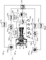
- FIG. 2 illustrates a hybrid electric propulsion system 100 (also referred to as hybrid gas turbine engine or hybrid electric engine 100) including a gas turbine engine 120 operably coupled to an electrical power system 210 as part of a hybrid electric aircraft.
- One or more mechanical power transmissions 150 can be operably coupled between the gas turbine engine 120 and the electrical power system 210.
- the gas turbine engine 120 can be an embodiment of the gas turbine engine 20 of FIG.
- the electrical power system 210 can include a first electric motor 212A configured to augment rotational power of the low speed spool 30 and a second electric motor 212B configured to augment rotational power of the high speed spool 32. Although two electric motors 212A, 212B are depicted in FIG.
- the electrical power system 210 can also include a first electric generator 213A configured to convert rotational power of the low speed spool 30 to electricity and a second electric generator 213B configured to convert rotational power of the high speed spool 32 to electricity.
- a first electric generator 213A configured to convert rotational power of the low speed spool 30 to electricity
- a second electric generator 213B configured to convert rotational power of the high speed spool 32 to electricity.
- two electric generators 213A, 213B are depicted in FIG. 2 , it will be understood that there may be only a single electric generator (e.g., only electric generator 213A) or additional electric generators (not depicted).
- one or more of the electric motors 212A, 212B can be configured as a motor or a generator depending upon an operational mode or system configuration, and thus one or more of the electric generators 213A, 213B may be omitted.
- the mechanical power transmission 150A can include a gearbox operably coupled between the inner shaft 40 and a combination of the first electric motor 212A and first electric generator 213A.
- the mechanical power transmission 150B can include a gearbox operably coupled between the outer shaft 50 and a combination of the second electric motor 212B and second electric generator 213B.
- the mechanical power transmission 150A, 150B can include a clutch or other interfacing element(s).
- the electrical power system 210 can also include motor drive electronics 214A, 214B operable to condition current to the electric motors 212A, 212B (e.g., DC-to-AC converters).
- the electrical power system 210 can also include rectifier electronics 215A, 215B operable to condition current from the electric generators 213A, 213B (e.g., AC-to-DC converters).
- the motor drive electronics 214A, 214B and rectifier electronics 215A, 215B can interface with an energy storage management system 216 that further interfaces with an energy storage system 218.
- the energy storage management system 216 can be a bi-directional DC-DC converter that regulates voltages between energy storage system 218 and electronics 214A, 214B, 215A, 215B.
- the energy storage system 218 can include one or more energy storage devices, such as a battery, a capacitor, a supercapacitor, an ultracapacitor, and the like.
- the energy storage management system 216 can facilitate various power transfers within the hybrid electric propulsion system or hybrid electric engine 100. For example, power from the first electric generator 213A can be transferred 211 to the second electric motor 212B as a low speed spool 30 to high speed spool 32 power transfer. Other examples of power transfers may include a power transfer from the second electric generator 213B to the first electric motor 212A as a high speed spool 32 to low speed spool 30 power transfer.
- a power conditioning unit 220 and/or other components can be powered by the energy storage system 218.
- the power conditioning unit 220 can distribute electric power to support actuation and other functions of the gas turbine engine 120.
- the power conditioning unit 220 can power an integrated fuel control unit 222 to control fuel flow to the gas turbine engine 120.
- the power conditioning unit 220 can power a plurality of actuators 224, such as one or more of a low pressure compressor bleed valve actuator 226, a low pressure compressor vane actuator 228, a high pressure compressor vane actuator 230, an active clearance control actuator 232, a variable area turbine actuator 234, and other such effectors.
- the low pressure compressor vane actuator 228 and/or the high pressure compressor vane actuator 230 can be omitted where active control of stator vanes 45, 55 of FIG. 1 is not needed.
- any effectors that can change a state of the gas turbine engine 120 and/or the electrical power system 210 may be referred to as hybrid electric system control effectors 240.
- Examples of the hybrid electric system control effectors 240 can include the electric motors 212A, 212B, electric generators 213A, 213B, integrated fuel control unit 222, actuators 224 and/or other elements (not depicted).
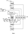
- FIG. 3 is a schematic diagram of control signal paths 250 of the hybrid electric propulsion system or hybrid electric engine 100 of FIG. 2 and is described with continued reference to FIGS. 1 and 2 .
- a controller 256 can interface with the motor drive electronics 214A, 214B, rectifier electronics 215A, 215B, energy storage management system 216, integrated fuel control unit 222, actuators 224, and/or other components (not depicted) of the hybrid electric propulsion system or hybrid electric engine 100.
- the controller 256 can control and monitor for fault conditions of the gas turbine engine 120 and/or the electrical power system 210.
- the controller 256 can be integrally formed or otherwise in communication with a full authority digital engine control (FADEC) of the gas turbine engine 120.
- FADEC full authority digital engine control
- the controller 256 can include a processing system 260, a memory system 262, and an input/output interface 264.
- the controller 256 can also include various operational controls, such as a power transfer control 266 that controls the hybrid electric system control effectors 240 as further described herein.
- the processing system 260 can include any type or combination of central processing unit (CPU), including one or more of: a microprocessor, a digital signal processor (DSP), a microcontroller, an application specific integrated circuit (ASIC), a field programmable gate array (FPGA), or the like.
- the memory system 262 can store data and instructions that are executed by the processing system 260.
- the memory system 262 may include random access memory (RAM), read only memory (ROM), or other electronic, optical, magnetic, or any other computer readable medium onto which is stored data and algorithms in a non-transitory form.
- the input/output interface 264 is configured to collect sensor data from the one or more system sensors and interface with various components and subsystems, such as components of the motor drive electronics 214A, 214B, rectifier electronics 215A, 215B, energy storage management system 216, integrated fuel control unit 222, actuators 224, and/or other components (not depicted) of the hybrid electric propulsion system or hybrid electric engine 100.
- the controller 256 provides a means for controlling the hybrid electric system control effectors 240 based on a power transfer control 266 that is dynamically updated during operation of the hybrid electric propulsion system or hybrid electric engine 100.
- the means for controlling the hybrid electric system control effectors 240 can be otherwise subdivided, distributed, or combined with other control elements.
- the power transfer control 266 can apply control laws and access/update models to determine how to control and transfer power to and from the hybrid electric system control effectors 240. For example, sensed and/or derived parameters related to speed, flow rate, pressure ratios, temperature, thrust, and the like can be used to establish operational schedules and transition limits to maintain efficient operation of the gas turbine engine 120.
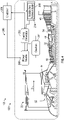
- a hybrid electric propulsion system 100 (also referred to as hybrid gas turbine engine or hybrid electric engine 100) including a gas turbine engine 120 operably coupled to an electrical power system 210 as part of a hybrid electric aircraft in accordance with one non-limiting embodiment of the present disclosure is illustrated.
- the engine 120 has a power source 280 such as a battery, a capacitor, a supercapacitor, an ultracapacitor or an equivalent thereof, which receives power to from an electric generator 282, which is connected to an engine accessory gearbox 284 that is operably coupled to the high speed spool 32.
- the accessory gearbox 284 will have at least one component (e.g., a gear train or other equivalent device) operably coupled to the high speed spool 32 and the electric generator 282 such that operation of the high speed spool 32 will rotate the component which in turn will rotate the electric generator 282.
- the power source 280 is configured to store electricity generated by the electric generator 282.
- the power source 280 is electrically connected to the electric generator 282 and the variable area turbine control system 288.
- electric generator 282 may be the electric generator 213B of the embodiment illustrated in FIG. 2 , which is configured to generate electricity from rotation of the high speed spool 32.
- electric generator 282 may be operatively coupled to the low speed spool 30 via the accessory gearbox 284.
- electric generator 282 may be electric generator 213A of the embodiment illustrated in FIG. 2 , which is configured to generate electricity from rotation of the low speed spool 30.
- the hybrid electric engine 100 includes a variable area turbine control system 288 electrically connected to the power source 280 and/or the electric generator 282.
- the variable area turbine control system 288 may be directly electrically connected to the electric generator 282 or connected to electric generator 282 through the power source 280.
- the variable area turbine control system 288 includes a variable area turbine actuator 234.
- the variable area turbine actuator 234 is configured to be powered only by electricity generated by the electric generator 282 and will not require electricity from any other source on the aircraft, which advantageously allows the variable area turbine actuator 234 to not be an electrical power drain on other aircraft power sources.
- variable area turbine control system 288 is configured to adjust the cross-sectional area of the core flow path C of the hybrid electric engine 100, thus increasing or decreasing core airflow through the core flow path C of the hybrid electric engine 100.
- the ability to increase or decreases core airflow through the core flow path C of the hybrid electric engine 100 is advantageous because it allows the hybrid electric engine 100 to spoil engine thrust independent of fuel flow to combustor 56 of the hybrid electric engine 100.
- the controller 256 is operably coupled with the electric generator 282 and the variable area turbine control system 288.
- the controller 256 is in electronic communication with the electric generator 282 and the variable area turbine control system 288.
- the controller 256 may also be operably coupled with the power source 280.
- the controller 256 may also be in electronic communication with the power source 280.
- the controller 256 may be a FADEC.
- the controller 256 may be configured to operate or control operation of the variable area turbine control system 288 and more specifically the variable area turbine actuator 234.
- variable area turbine control system 288 is illustrated in accordance with an embodiment of the present disclosure.
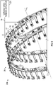
- FIG. 5 illustrates variable area turbine control system 288 configured to adjust a cross-sectional area of the core flow path C within a turbine section 28 of the hybrid electric engine 100 using a plurality of variable turbine vanes 72.
- the variable turbine vanes 72 are static vanes, meaning that the variable turbine vanes 72 do not rotate around the engine central longitudinal axis A.
- the variable turbine vanes 72 only rotate around a vane stem axis D.
- the variable area turbine control system 288 includes a vane arm 64. It is understood that while only one variable turbine vane 72 is illustrated in FIG. 5 for simplicity, the variable area turbine control system 288 includes one variable turbine vane 72 for each vane arm 64.
- the vane arm 64 is operably couped to an actuation ring 66. It is understood that although discussed as a single actuation ring 66, the actuation ring 66 may be composed of multiple components integrally formed or connected. Rotating the actuation ring 66 circumferentially about the engine central longitudinal axis A moves the vane arm 64 to pivot a vane stem 68, and an associated variable turbine vane 72. The vane stem 68 is pivoted around the vane stem axis D. The vane arm 64 is used to manipulate variable turbine vanes 72 in the turbine section 28 of the hybrid electric engine 100.
- the variable area turbine actuator 234 is configured to rotate the variable turbine vane 72 around a vane stem axis D to adjust the cross-sectional area of the core flow path C within a turbine section 28 of the hybrid electric engine 100.
- the vane stem axis D extends from the central engine longitudinal axis A radially outward through the vane stem 68.
- the vane stem axis D may be located central to the vane stem 68.
- variable area turbine actuator 234 is an electromechanical actuator.
- the variable area turbine actuator 234 is operably connected to the actuation ring 66 through a series of mechanical linkages 94.
- the mechanical linkages 94 may include a bell crank that is operably attached to the variable area turbine actuator 234. The bell crank may penetrate the turbine case to drive the actuation rings 66, which moves the individual variable turbine vanes 72.
- the variable area turbine actuator 234 is configured to rotate the actuation rings 66 circumferentially about the engine central longitudinal axis A through the series of mechanical linkages 94, which moves the vane arm 64 to pivot the vane stem 68, and an associated variable turbine vane 72.
- a pin 74 is operably connected to the vane arm 64 at a first end 76 of the vane arm 64.
- the pin 74 operably connects the vane arm 64 to the actuation ring 66 and allows the pin 74 and vane arm 64 rotate together.
- the pin 74 is radially received within a sync ring bushing 86, which is received within a sleeve (not shown) within the actuation (or sync) ring 66.
- the bushing 86 permits the pin 74 and the vane arm 64 to rotate together relative to the actuation ring 66.
- the pin 74 may be oriented relative to the vane arm 64 such that the pin 74 extends radially toward the central engine longitudinal axis A.
- the vane stem 68 is secured to a second end 88 of the vane arm 64 opposite the first end 76.
- the vane stems 68 may be secured to the second end 88 via a fastening mechanism 164.
- the fastening mechanism 164 may be a nut.
- the vane arm 64 and vane stem 68 rotate in unison.
- variable area turbine actuator 234 may be utilized with other similar mechanisms to rotate turbine vanes 72.
- Fig. 6 illustrated a method 500 of managing airflow through a core flow path C of a hybrid electric engine 100 for an aircraft.
- an electric generator 282 converts rotational power of a high speed spool 32 of the hybrid electric engine 100 or a low speed spool 30 of the hybrid electric engine 100 to electricity.
- variable area turbine control system 288 includes: a plurality of variable turbine vanes 72 located in a turbine section 28 of the hybrid electric engine 100 and a variable area turbine actuator 234.
- variable area turbine actuator 234 rotates each of the plurality of variable turbine vanes 72 to adjust a cross-sectional area of the core flow path C of the hybrid electric engine 100.
- the variable area turbine actuator 234 is an electromechanical actuator.
- the method 500 may further comprise that the controller 256 commands delivery of enough fuel to the hybrid electric engine 100 during a taxi of the aircraft to maintain a minimum fuel flow requirement for the hybrid electric engine 100 and the variable area turbine actuator 234 rotates each of the plurality of variable turbine vanes 72 to increase the cross-sectional area of the core flow path C through the turbine section 28 of the hybrid electric engine 100 to reduce the compressor operating line, thereby improving idle stability and allowing for reduced idle thrust. Better matching the turbine area to the compressor operation line at take-off may also be used to manage temperatures and improve durability.
- the method 500 may further comprise that electricity generated by the electric generator 282 using a power source 280 electrically connected to the electric generator 282 and the variable area turbine control system 288.
- the variable area turbine control system 288 is electrically connected to the electric generator 282 through the power source 280.
- radially outward is intended to be in the direction away from the engine central longitudinal axis A.
Landscapes
- Engineering & Computer Science (AREA)
- Mechanical Engineering (AREA)
- General Engineering & Computer Science (AREA)
- Chemical & Material Sciences (AREA)
- Combustion & Propulsion (AREA)
- Physics & Mathematics (AREA)
- Fluid Mechanics (AREA)
- Control Of Turbines (AREA)
Applications Claiming Priority (1)
| Application Number | Priority Date | Filing Date | Title |
|---|---|---|---|
| US17/360,480 US11867069B2 (en) | 2021-06-28 | 2021-06-28 | Hybrid electric variable area turbine |
Publications (1)
| Publication Number | Publication Date |
|---|---|
| EP4112909A1 true EP4112909A1 (de) | 2023-01-04 |
Family
ID=82321399
Family Applications (1)
| Application Number | Title | Priority Date | Filing Date |
|---|---|---|---|
| EP22181383.5A Pending EP4112909A1 (de) | 2021-06-28 | 2022-06-27 | Hybridelektrische turbine mit variabler fläche |
Country Status (2)
| Country | Link |
|---|---|
| US (1) | US11867069B2 (de) |
| EP (1) | EP4112909A1 (de) |
Cited By (1)
| Publication number | Priority date | Publication date | Assignee | Title |
|---|---|---|---|---|
| EP4407163A1 (de) * | 2023-01-27 | 2024-07-31 | RTX Corporation | Kondensationskontrolle für einen turbinenmotor mit dampfeinspritzung |
Families Citing this family (2)
| Publication number | Priority date | Publication date | Assignee | Title |
|---|---|---|---|---|
| EP4173957A1 (de) * | 2021-10-29 | 2023-05-03 | Raytheon Technologies Corporation | Energiemanagement bei ausfall eines triebwerks im sinkflug für ein hybrid-elektrisches antriebssystem |
| US20260092561A1 (en) * | 2024-10-01 | 2026-04-02 | Rtx Corporation | Turbine cooling air throttling valve and system for hybrid electric engines |
Citations (4)
| Publication number | Priority date | Publication date | Assignee | Title |
|---|---|---|---|---|
| US20100000223A1 (en) * | 2007-02-19 | 2010-01-07 | Snecma | Method of taking off auxiliary power from an airplane turbojet, and a turbojet fitted to implement such a method |
| US20160369745A1 (en) * | 2015-06-18 | 2016-12-22 | Hamilton Sundstrand Corporation | Actuator control system and method for gas turbine engine |
| EP3708803A1 (de) * | 2019-03-12 | 2020-09-16 | United Technologies Corporation | Variabler reaktionsfreilauf für einen turbinenabschnitt eines gasturbinenmotors |
| US20200362768A1 (en) * | 2019-05-15 | 2020-11-19 | Honeywell International Inc. | Variable area turbine nozzle and method |
Family Cites Families (10)
| Publication number | Priority date | Publication date | Assignee | Title |
|---|---|---|---|---|
| GB9606546D0 (en) | 1996-03-28 | 1996-06-05 | Rolls Royce Plc | Gas turbine engine system |
| US8007229B2 (en) * | 2007-05-24 | 2011-08-30 | United Technologies Corporation | Variable area turbine vane arrangement |
| US10196923B2 (en) * | 2014-08-28 | 2019-02-05 | Pratt & Whitney Canada Corp. | Operation of aircraft engines during transient conditions |
| EP3035504B1 (de) | 2014-12-18 | 2017-07-26 | Rolls-Royce plc | Elektrische maschinen |
| US10180076B2 (en) * | 2015-06-01 | 2019-01-15 | Hamilton Sundstrand Corporation | Redundant speed summing actuators |
| US10253648B2 (en) * | 2016-03-04 | 2019-04-09 | General Electric Company | Modulated hybrid variable area turbine nozzle for gas turbine engine |
| US10378455B2 (en) * | 2017-08-28 | 2019-08-13 | United Technologies Corporation | Method for selection of optimal engine operating conditions for generating linearized models for on-board control and estimation |
| US10981660B2 (en) * | 2018-04-19 | 2021-04-20 | The Boeing Company | Hybrid propulsion engines for aircraft |
| US11565821B2 (en) * | 2018-07-30 | 2023-01-31 | Raytheon Technologies Corporation | Hybrid energy storage system control for an aircraft engine |
| US10907494B2 (en) * | 2019-04-30 | 2021-02-02 | Rolls-Royce North American Technologies Inc. | Parallel hybrid propulsion system |
-
2021
- 2021-06-28 US US17/360,480 patent/US11867069B2/en active Active
-
2022
- 2022-06-27 EP EP22181383.5A patent/EP4112909A1/de active Pending
Patent Citations (4)
| Publication number | Priority date | Publication date | Assignee | Title |
|---|---|---|---|---|
| US20100000223A1 (en) * | 2007-02-19 | 2010-01-07 | Snecma | Method of taking off auxiliary power from an airplane turbojet, and a turbojet fitted to implement such a method |
| US20160369745A1 (en) * | 2015-06-18 | 2016-12-22 | Hamilton Sundstrand Corporation | Actuator control system and method for gas turbine engine |
| EP3708803A1 (de) * | 2019-03-12 | 2020-09-16 | United Technologies Corporation | Variabler reaktionsfreilauf für einen turbinenabschnitt eines gasturbinenmotors |
| US20200362768A1 (en) * | 2019-05-15 | 2020-11-19 | Honeywell International Inc. | Variable area turbine nozzle and method |
Cited By (1)
| Publication number | Priority date | Publication date | Assignee | Title |
|---|---|---|---|---|
| EP4407163A1 (de) * | 2023-01-27 | 2024-07-31 | RTX Corporation | Kondensationskontrolle für einen turbinenmotor mit dampfeinspritzung |
Also Published As
| Publication number | Publication date |
|---|---|
| US20220412272A1 (en) | 2022-12-29 |
| US11867069B2 (en) | 2024-01-09 |
Similar Documents
| Publication | Publication Date | Title |
|---|---|---|
| EP3789603B1 (de) | Elektrische hilfskraftunterstützung für motorneustart im flug | |
| EP4112909A1 (de) | Hybridelektrische turbine mit variabler fläche | |
| EP3779147B1 (de) | Rotordynamikausgleich unter verwendung von elektrischem hilfsantrieb | |
| EP4352349B1 (de) | Ölzirkulationssystem für hybride elektrische motoren | |
| US12123344B2 (en) | Engine and secondary power unit integrated operation | |
| US11821372B2 (en) | Hybrid electric engine with electric tip clearance mechanism | |
| EP3767090B2 (de) | Steuerung der betriebsfähigkeit eines kompressors für einen hybriden elektrischen antrieb | |
| EP4102044A2 (de) | Elektrische hybridmotorleistungsverteilung | |
| EP4102046A1 (de) | Hybrid-elektrischer leerlaufübergang für flugzeuge | |
| EP4421299A2 (de) | Hybrider elektrischer motor und gondelsystem | |
| EP3772579B1 (de) | Wellenkupplungssystem für gasturbinenmotor | |
| EP3767092B1 (de) | Modulierter brennkammer-bypass für hybridleerlauf | |
| US11557995B2 (en) | Aircraft engine power-assist start stability control | |
| EP3779150B1 (de) | Verbesserung bei der materialermüdung für hybride antriebssysteme |
Legal Events
| Date | Code | Title | Description |
|---|---|---|---|
| PUAI | Public reference made under article 153(3) epc to a published international application that has entered the european phase |
Free format text: ORIGINAL CODE: 0009012 |
|
| STAA | Information on the status of an ep patent application or granted ep patent |
Free format text: STATUS: THE APPLICATION HAS BEEN PUBLISHED |
|
| AK | Designated contracting states |
Kind code of ref document: A1 Designated state(s): AL AT BE BG CH CY CZ DE DK EE ES FI FR GB GR HR HU IE IS IT LI LT LU LV MC MK MT NL NO PL PT RO RS SE SI SK SM TR |
|
| STAA | Information on the status of an ep patent application or granted ep patent |
Free format text: STATUS: REQUEST FOR EXAMINATION WAS MADE |
|
| 17P | Request for examination filed |
Effective date: 20230704 |
|
| RBV | Designated contracting states (corrected) |
Designated state(s): AL AT BE BG CH CY CZ DE DK EE ES FI FR GB GR HR HU IE IS IT LI LT LU LV MC MK MT NL NO PL PT RO RS SE SI SK SM TR |
|
| RAP3 | Party data changed (applicant data changed or rights of an application transferred) |
Owner name: RTX CORPORATION |
|
| STAA | Information on the status of an ep patent application or granted ep patent |
Free format text: STATUS: EXAMINATION IS IN PROGRESS |
|
| 17Q | First examination report despatched |
Effective date: 20241220 |