EP3790157A1 - Distribution de puissance optimisée vers des systèmes de régulation climatique dans le transport parmi une ou plusieurs stations d'équipement d'alimentation électrique - Google Patents
Distribution de puissance optimisée vers des systèmes de régulation climatique dans le transport parmi une ou plusieurs stations d'équipement d'alimentation électrique Download PDFInfo
- Publication number
- EP3790157A1 EP3790157A1 EP20195238.9A EP20195238A EP3790157A1 EP 3790157 A1 EP3790157 A1 EP 3790157A1 EP 20195238 A EP20195238 A EP 20195238A EP 3790157 A1 EP3790157 A1 EP 3790157A1
- Authority
- EP
- European Patent Office
- Prior art keywords
- power
- climate control
- power distribution
- data
- transport climate
- Prior art date
- Legal status (The legal status is an assumption and is not a legal conclusion. Google has not performed a legal analysis and makes no representation as to the accuracy of the status listed.)
- Pending
Links
Images


Classifications
-
- B—PERFORMING OPERATIONS; TRANSPORTING
- B60—VEHICLES IN GENERAL
- B60H—ARRANGEMENTS OF HEATING, COOLING, VENTILATING OR OTHER AIR-TREATING DEVICES SPECIALLY ADAPTED FOR PASSENGER OR GOODS SPACES OF VEHICLES
- B60H1/00—Heating, cooling or ventilating devices
- B60H1/00421—Driving arrangements for parts of a vehicle air-conditioning
- B60H1/00428—Driving arrangements for parts of a vehicle air-conditioning electric
-
- H—ELECTRICITY
- H02—GENERATION; CONVERSION OR DISTRIBUTION OF ELECTRIC POWER
- H02J—ELECTRIC POWER NETWORKS; CIRCUIT ARRANGEMENTS OR SYSTEMS FOR SUPPLYING OR DISTRIBUTING ELECTRIC POWER; SYSTEMS FOR STORING ELECTRIC ENERGY
- H02J13/00—Circuit arrangements for providing remote monitoring or remote control of equipment in a power distribution network
- H02J13/16—Circuit arrangements for providing remote monitoring or remote control of equipment in a power distribution network the power network being controlled at grid-level, e.g. using aggregators
-
- B—PERFORMING OPERATIONS; TRANSPORTING
- B60—VEHICLES IN GENERAL
- B60H—ARRANGEMENTS OF HEATING, COOLING, VENTILATING OR OTHER AIR-TREATING DEVICES SPECIALLY ADAPTED FOR PASSENGER OR GOODS SPACES OF VEHICLES
- B60H1/00—Heating, cooling or ventilating devices
- B60H1/32—Cooling devices
- B60H1/3204—Cooling devices using compression
- B60H1/3232—Cooling devices using compression particularly adapted for load transporting vehicles
-
- H—ELECTRICITY
- H02—GENERATION; CONVERSION OR DISTRIBUTION OF ELECTRIC POWER
- H02J—ELECTRIC POWER NETWORKS; CIRCUIT ARRANGEMENTS OR SYSTEMS FOR SUPPLYING OR DISTRIBUTING ELECTRIC POWER; SYSTEMS FOR STORING ELECTRIC ENERGY
- H02J1/00—Circuit arrangements for DC mains or DC distribution networks
- H02J1/10—Parallel operation of DC sources
- H02J1/106—Parallel operation of DC sources for load balancing, symmetrisation, or sharing
-
- H—ELECTRICITY
- H02—GENERATION; CONVERSION OR DISTRIBUTION OF ELECTRIC POWER
- H02J—ELECTRIC POWER NETWORKS; CIRCUIT ARRANGEMENTS OR SYSTEMS FOR SUPPLYING OR DISTRIBUTING ELECTRIC POWER; SYSTEMS FOR STORING ELECTRIC ENERGY
- H02J1/00—Circuit arrangements for DC mains or DC distribution networks
- H02J1/14—Balancing load and power generation in DC networks
-
- H—ELECTRICITY
- H02—GENERATION; CONVERSION OR DISTRIBUTION OF ELECTRIC POWER
- H02J—ELECTRIC POWER NETWORKS; CIRCUIT ARRANGEMENTS OR SYSTEMS FOR SUPPLYING OR DISTRIBUTING ELECTRIC POWER; SYSTEMS FOR STORING ELECTRIC ENERGY
- H02J3/00—Circuit arrangements for AC mains or AC distribution networks
- H02J3/007—Arrangements for selectively connecting one or more loads to one or more power sources or power lines
-
- H—ELECTRICITY
- H02—GENERATION; CONVERSION OR DISTRIBUTION OF ELECTRIC POWER
- H02J—ELECTRIC POWER NETWORKS; CIRCUIT ARRANGEMENTS OR SYSTEMS FOR SUPPLYING OR DISTRIBUTING ELECTRIC POWER; SYSTEMS FOR STORING ELECTRIC ENERGY
- H02J3/00—Circuit arrangements for AC mains or AC distribution networks
- H02J3/28—Arrangements for balancing of the load in networks by storage of energy
- H02J3/32—Arrangements for balancing of the load in networks by storage of energy using batteries or super capacitors with converting means
-
- H—ELECTRICITY
- H02—GENERATION; CONVERSION OR DISTRIBUTION OF ELECTRIC POWER
- H02J—ELECTRIC POWER NETWORKS; CIRCUIT ARRANGEMENTS OR SYSTEMS FOR SUPPLYING OR DISTRIBUTING ELECTRIC POWER; SYSTEMS FOR STORING ELECTRIC ENERGY
- H02J2105/00—Networks for supplying or distributing electric power characterised by their spatial reach or by the load
- H02J2105/30—Networks for supplying or distributing electric power characterised by their spatial reach or by the load the load networks being external to vehicles, i.e. exchanging power with vehicles
-
- H—ELECTRICITY
- H02—GENERATION; CONVERSION OR DISTRIBUTION OF ELECTRIC POWER
- H02J—ELECTRIC POWER NETWORKS; CIRCUIT ARRANGEMENTS OR SYSTEMS FOR SUPPLYING OR DISTRIBUTING ELECTRIC POWER; SYSTEMS FOR STORING ELECTRIC ENERGY
- H02J2105/00—Networks for supplying or distributing electric power characterised by their spatial reach or by the load
- H02J2105/50—Networks for supplying or distributing electric power characterised by their spatial reach or by the load for selectively controlling the operation of the loads
- H02J2105/52—Networks for supplying or distributing electric power characterised by their spatial reach or by the load for selectively controlling the operation of the loads for limitation of the power consumption in the networks or in one section of the networks, e.g. load shedding or peak shaving
-
- Y—GENERAL TAGGING OF NEW TECHNOLOGICAL DEVELOPMENTS; GENERAL TAGGING OF CROSS-SECTIONAL TECHNOLOGIES SPANNING OVER SEVERAL SECTIONS OF THE IPC; TECHNICAL SUBJECTS COVERED BY FORMER USPC CROSS-REFERENCE ART COLLECTIONS [XRACs] AND DIGESTS
- Y02—TECHNOLOGIES OR APPLICATIONS FOR MITIGATION OR ADAPTATION AGAINST CLIMATE CHANGE
- Y02T—CLIMATE CHANGE MITIGATION TECHNOLOGIES RELATED TO TRANSPORTATION
- Y02T10/00—Road transport of goods or passengers
- Y02T10/80—Technologies aiming to reduce greenhouse gasses emissions common to all road transportation technologies
- Y02T10/88—Optimized components or subsystems, e.g. lighting, actively controlled glasses
Definitions
- the disclosure herein relates to an electrically powered accessory configured to be used with at least one of a vehicle, trailer, and a transport container. More particularly, the disclosure herein relates to an optimized power distribution to electrically powered accessories amongst one or more electric supply equipment stations.
- a transport climate control system is generally used to control environmental condition(s) (e.g., temperature, humidity, air quality, and the like) within a climate controlled space of a transport unit (e.g., a truck, a container (such as a container on a flat car, an intermodal container, etc.), a box car, a semi-tractor, a bus, or other similar transport unit).
- the transport climate control system can include, for example, a transport refrigeration system (TRS) and/or a heating, ventilation and air conditioning (HVAC) system.
- TRS transport refrigeration system
- HVAC heating, ventilation and air conditioning
- the TRS can control environmental condition(s) within the climate controlled space to maintain cargo (e.g., produce, frozen foods, pharmaceuticals, etc.).
- the HVAC system can control environmental conditions(s) within the climate controlled space to provide passenger comfort for passengers travelling in the transport unit.
- the transport climate control system can be installed externally (e.g., on a rooftop of the transport unit, on a front wall of the transport unit, etc.).
- the embodiments disclosed herein relate to an electrically powered accessory configured to be used with at least one of a vehicle, trailer, and a transport container. More particularly, the embodiments disclosed herein relate to an optimized power distribution to electrically powered accessories amongst one or more electric supply equipment stations.
- the embodiments described herein can power and/or charge one or more electrically powered accessories and at the same time maintain logistical processes for operating the one or more electrically powered accessories and maintain dispatch schedules for the one or more electrically powered accessories while minimizing costs related to, for example, power demand rates, etc.
- the embodiments described herein can coordinate power distribution to one or more electrically powered accessories at a power distribution site based on infrastructure data about the power distribution site, vehicle/electrically powered accessory data from one or more electrically powered accessories demanding power from one or more electrical supply equipment (ESE) stations (e.g., electrical vehicle supply equipment) located at the power distribution site, and external data from an external source that can impact power demand from the one or more electrically powered accessories.
- ESE electrical supply equipment
- the infrastructure data, the electrically powered accessory data, and the external data can be from various inputs and use simulation models and historical data to predict an optimization model for scheduling power distribution to the one or more electrically powered accessories while minimizing overall cost (e.g., power distribution site costs, operational costs of the electrically powered accessories, etc.) and ensuring that the electrically powered accessories have sufficient power to operate while at the power distribution site and/or sufficient charge to operate when the electrically powered accessory is dispatched from the power distribution site.
- overall cost e.g., power distribution site costs, operational costs of the electrically powered accessories, etc.
- the power distribution site can be modular such that power distribution capacity can be increased or decreased as required and can be flexible such that the power distribution site includes multiple ESE stations that may or may not be capable of distributing power at any given time. Also, in some embodiments, the power distribution site can determine whether a new ESE station has been added to or removed from the power distribution site. Accordingly, the embodiment described herein can reduce costs for a power distribution site by reducing the amount of power distributed at peak power demand rates, can reduce capacity strain on the power distribution site and can enable energy balancing amongst the multiple ESE stations.
- the embodiments described herein can ensure climate control for each of the CCUs, and optimize timing for starting, for example, a temperature pull down for each of the CCUs and/or speed for the temperature pull down for each of the CCUs.
- the embodiments described herein can help ensure successful climate control of each of the CCUs and provide particular focus to the CCUs providing climate control to relatively more valuable and/or climate sensitive cargo.
- a method for optimizing power distribution amongst one or more electrical supply equipment stations at a power distribution site includes obtaining infrastructure data about the power distribution site, obtaining vehicle/electrically powered accessory data from one or more electrically powered accessories and one or more vehicles demanding power from the one or more electrical supply equipment, and obtaining external data from an external source that can impact power demand from the one or more electrically powered accessories.
- Each of the one or more electrically powered accessories is configured to be used with at least one of a vehicle, a trailer, and a transportation container.
- the method also includes generating an optimized power distribution schedule based on the infrastructure data, the vehicle/electrically powered accessory data and the external data, and distributing power to the one or more electrically powered accessories based on the optimized power distribution schedule.
- a power distribution site for distributing power to one or more electrically powered accessories.
- the power distribution site includes a power converter stage, a plurality of electrical supply equipment stations, a transfer switch matrix, and a power distribution controller.
- the power converter stage is configured to convert power received from one or more of a plurality of power sources into a power that is compatible with at least one of the one or more electrically powered accessories.
- the plurality of electrical supply equipment stations distribute power received from the power converter stage to at least one of the one or more electrically powered accessories.
- the transfer switch matrix is selectively connected to each of the plurality of electrical supply equipment stations, wherein the transfer switch matrix selectively distributes power converted by the power converter stage to at least one of the one or more electrically powered accessories.
- the power distribution controller controls distribution of power to the one or more electrically powered accessories by controlling operation of the power converter stage and the transfer switch matrix.
- the embodiments disclosed herein relate to an electrically powered accessory configured to be used with at least one of a vehicle, trailer, and a transport container. More particularly, the embodiments disclosed herein relate to optimized power distribution to electrically powered accessories amongst one or more electric supply equipment stations.
- the electrically powered accessory is not limited to the transport climate control system or a climate control unit (CCU) of the transport climate control system.
- a CCU can be e.g., a transport refrigeration unit (TRU).
- the electrically powered accessory can be, for example, a crane attached to a vehicle, a cement mixer attached to a truck, one or more food appliances of a food truck, a boom arm attached to a vehicle, a concrete pumping truck, a refuse truck, a fire truck (with a power driven ladder, pumps, lights, etc.), etc.
- the electrically powered accessory may require continuous operation even when the vehicle's ignition is turned off and/or the vehicle is parked and/or idling and/or charging.
- the electrically powered accessory can require substantial power to operate and/or continuous and/or autonomous operation (e.g., controlling temperature/humidity/airflow of a climate controlled space) on an as needed basis, independent of the vehicle's operational mode.
- the electrically powered accessory is not limited to the transport climate control system or a climate control unit (CCU) of the transport climate control system.
- a CCU can be e.g., a transport refrigeration unit (TRU).
- the electrically powered accessory can be, for example, a crane attached to a vehicle, a cement mixer attached to a truck, one or more food appliances of a food truck, a boom arm attached to a vehicle, a concrete pumping truck, a refuse truck, a fire truck (with a power driven ladder, pumps, lights, etc.), etc.
- the electrically powered accessory may require continuous operation even when the vehicle's ignition is turned off and/or the vehicle is parked and/or idling and/or charging.
- the electrically powered accessory can require substantial power to operate and/or continuous and/or autonomous operation (e.g., controlling temperature/humidity/airflow of a climate controlled space) on an as needed basis, independent of the vehicle's operational mode.
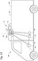
- Fig. 1A depicts a climate-controlled van 100 that includes a climate controlled space 105 for carrying cargo and a transport climate control system 110 for providing climate control within the climate controlled space 105.
- the transport climate control system 110 includes a climate control unit (CCU) 115 that is mounted to a rooftop 120 of the van 100.
- the transport climate control system 110 can include, amongst other components, a climate control circuit (not shown) that connects, for example, a compressor, a condenser, an evaporator and an expansion device to provide climate control within the climate controlled space 105.
- climate-controlled vans can apply to any type of transport unit (e.g., a truck, a container (such as a container on a flat car, an intermodal container, a marine container, etc.), a box car, a semi-tractor, a bus, or other similar transport unit), etc.
- transport unit e.g., a truck, a container (such as a container on a flat car, an intermodal container, a marine container, etc.), a box car, a semi-tractor, a bus, or other similar transport unit), etc.
- the transport climate control system 110 also includes a programmable climate controller 125 and one or more sensors (not shown) that are configured to measure one or more parameters of the transport climate control system 110 (e.g., an ambient temperature outside of the van 100, an ambient humidity outside of the van 100, a compressor suction pressure, a compressor discharge pressure, a supply air temperature of air supplied by the CCU 115 into the climate controlled space 105, a return air temperature of air returned from the climate controlled space 105 back to the CCU 115, a humidity within the climate controlled space 105, etc.) and communicate parameter data to the climate controller 125.
- the climate controller 125 is configured to control operation of the transport climate control system 110 including the components of the climate control circuit.
- the climate controller unit 115 may comprise a single integrated control unit 126 or may comprise a distributed network of climate controller elements 126, 127. The number of distributed control elements in a given network can depend upon the particular application of the principles described herein.
- the climate-controlled van 100 can also include a vehicle PDU 101, a VES 102, a standard charging port 103, and/or an enhanced charging port 104.
- the VES 102 can include a controller (not shown).
- the vehicle PDU 101 can include a controller (not shown).
- the vehicle PDU controller can be a part of the VES controller or vice versa.
- power can be distributed from e.g., an electric vehicle supply equipment (EVSE, not shown), via the standard charging port 103, to the vehicle PDU 101.
- Power can also be distributed from the vehicle PDU 101 to an electrical supply equipment (ESE, not shown) and/or to the CCU 115 (see solid lines for power lines and dotted lines for communication lines).
- ESE electrical supply equipment
- power can be distributed from e.g., an EVSE (not shown), via the enhanced charging port 104, to an ESE (not shown) and/or to the CCU 115.
- the ESE can then distribute power to the vehicle PDU 101 via the standard charging port 103.
- Fig. 1B depicts a climate-controlled straight truck 130 that includes a climate controlled space 131 for carrying cargo and a transport climate control system 132.
- the transport climate control system 132 includes a CCU 133 that is mounted to a front wall 134 of the climate controlled space 131.
- the CCU 133 can include, amongst other components, a climate control circuit (not shown) that connects, for example, a compressor, a condenser, an evaporator and an expansion device to provide climate control within the climate controlled space 131.
- the transport climate control system 132 also includes a programmable climate controller 135 and one or more sensors (not shown) that are configured to measure one or more parameters of the transport climate control system 132 (e.g., an ambient temperature outside of the truck 130, an ambient humidity outside of the truck 130, a compressor suction pressure, a compressor discharge pressure, a supply air temperature of air supplied by the CCU 133 into the climate controlled space 131, a return air temperature of air returned from the climate controlled space 131 back to the CCU 133, a humidity within the climate controlled space 131, etc.) and communicate parameter data to the climate controller 135.
- the climate controller 135 is configured to control operation of the transport climate control system 132 including components of the climate control circuit.
- the climate controller 135 may comprise a single integrated control unit 136 or may comprise a distributed network of climate controller elements 136, 137. The number of distributed control elements in a given network can depend upon the particular application of the principles described herein.
- the climate-controlled straight truck 130 of Fig. 1B can also include a vehicle PDU (such as the vehicle PDU 101 shown in Fig. 1A ), a VES (such as the VES 102 shown in Fig. 1A ), a standard charging port (such as the standard charging port 103 shown in Fig. 1A ), and/or an enhanced charging port (e.g., the enhanced charging port 104 shown in Fig. 1A ), communicating with and distribute power from/to the corresponding ESE and/or the CCU 133.
- a vehicle PDU such as the vehicle PDU 101 shown in Fig. 1A
- VES such as the VES 102 shown in Fig. 1A
- a standard charging port such as the standard charging port 103 shown in Fig. 1A
- an enhanced charging port e.g., the enhanced charging port 104 shown in Fig. 1A
- Fig. 1C illustrates one embodiment of a climate controlled transport unit 140 attached to a tractor 142.
- the climate controlled transport unit 140 includes a transport climate control system 145 for a transport unit 150.
- the tractor 142 is attached to and is configured to tow the transport unit 150.
- the transport unit 150 shown in Fig. 1C is a trailer.
- the transport climate control system 145 includes a CCU 152 that provides environmental control (e.g. temperature, humidity, air quality, etc.) within a climate controlled space 154 of the transport unit 150.
- the CCU 152 is disposed on a front wall 157 of the transport unit 150. In other embodiments, it will be appreciated that the CCU 152 can be disposed, for example, on a rooftop or another wall of the transport unit 150.
- the CCU 152 includes a climate control circuit (not shown) that connects, for example, a compressor, a condenser, an evaporator and an expansion device to provide conditioned air within the climate controlled space 154.
- the transport climate control system 145 also includes a programmable climate controller 156 and one or more sensors (not shown) that are configured to measure one or more parameters of the transport climate control system 145 (e.g., an ambient temperature outside of the transport unit 150, an ambient humidity outside of the transport unit 150, a compressor suction pressure, a compressor discharge pressure, a supply air temperature of air supplied by the CCU 152 into the climate controlled space 154, a return air temperature of air returned from the climate controlled space 154 back to the CCU 152, a humidity within the climate controlled space 154, etc.) and communicate parameter data to the climate controller 156.
- the climate controller 156 is configured to control operation of the transport climate control system 145 including components of the climate control circuit.
- the climate controller 156 may comprise a single integrated control unit 158 or may comprise a distributed network of climate controller elements 158, 159. The number of distributed control elements in a given network can depend upon the particular application of the principles described herein.
- the tractor 142 can include an optional APU 108.
- the optional APU 108 can be an electric auxiliary power unit (eAPU).
- the tractor 142 can also include a vehicle PDU 101 and a VES 102 (not shown).
- the APU 108 can provide power to the vehicle PDU 101 for distribution. It will be appreciated that for the connections, solid lines represent power lines and dotted lines represent communication lines.
- the climate controlled transport unit 140 can include a PDU 121 connecting to power sources (including, for example, an optional solar power source 109; an optional power source 122 such as Genset, fuel cell, undermount power unit, auxiliary battery pack, etc.; and/or an optional liftgate battery 107, etc.) of the climate controlled transport unit 140.
- the PDU 121 can include a PDU controller (not shown).
- the PDU controller can be a part of the climate controller 156.
- the PDU 121 can distribute power from the power sources of the climate controlled transport unit 140 to e.g., the transport climate control system 145.
- the climate controlled transport unit 140 can also include an optional liftgate 106.
- the optional liftgate battery 107 can provide power to open and/or close the liftgate 106.
- the climate controlled transport unit 140 attached to the tractor 142 of Fig. 1C can also include a VES (such as the VES 102 shown in Fig. 1A ), a standard charging port (such as the standard charging port 103 shown in Fig. 1A ), and/or an enhanced charging port (such as the enhanced charging port 104 shown in Fig. 1A ), communicating with and distribute power from/to a corresponding ESE and/or the CCU 152.
- the charging port(s) 103 and/or can be on either the tractor 142 or the trailer.
- the standard charging port 103 is on the tractor 142 and the enhanced charging port 104 is on the trailer.
- Fig. ID illustrates another embodiment of a climate controlled transport unit 160.
- the climate controlled transport unit 160 includes a multi-zone transport climate control system (MTCS) 162 for a transport unit 164 that can be towed, for example, by a tractor (not shown).
- MTCS multi-zone transport climate control system
- transport unit 164 that can be towed, for example, by a tractor (not shown).
- MTCS multi-zone transport climate control system
- a transport unit 164 that can be towed, for example, by a tractor (not shown).
- a tractor not shown
- the embodiments described herein are not limited to tractor and trailer units, but can apply to any type of transport unit (e.g., a truck, a container (such as a container on a flat car, an intermodal container, a marine container, etc.), a box car, a semi-tractor, a bus, or other similar transport unit), etc.
- the MTCS 162 includes a CCU 166 and a plurality of remote units 168 that provide environmental control (e.g. temperature, humidity, air quality, etc.) within a climate controlled space 170 of the transport unit 164.
- the climate controlled space 170 can be divided into a plurality of zones 172.
- the term "zone" means a part of an area of the climate controlled space 170 separated by walls 174.
- the CCU 166 can operate as a host unit and provide climate control within a first zone 172a of the climate controlled space 166.
- the remote unit 168a can provide climate control within a second zone 172b of the climate controlled space 170.
- the remote unit 168b can provide climate control within a third zone 172c of the climate controlled space 170. Accordingly, the MTCS 162 can be used to separately and independently control environmental condition(s) within each of the multiple zones 172 of the climate controlled space 162.
- the CCU 166 is disposed on a front wall 167 of the transport unit 160. In other embodiments, it will be appreciated that the CCU 166 can be disposed, for example, on a rooftop or another wall of the transport unit 160.
- the CCU 166 includes a climate control circuit (not shown) that connects, for example, a compressor, a condenser, an evaporator and an expansion device to provide conditioned air within the climate controlled space 170.
- the remote unit 168a is disposed on a ceiling 179 within the second zone 172b and the remote unit 168b is disposed on the ceiling 179 within the third zone 172c.
- Each of the remote units 168a,b include an evaporator (not shown) that connects to the rest of the climate control circuit provided in the CCU 166.
- the MTCS 162 also includes a programmable climate controller 180 and one or more sensors (not shown) that are configured to measure one or more parameters of the MTCS 162 (e.g., an ambient temperature outside of the transport unit 164, an ambient humidity outside of the transport unit 164, a compressor suction pressure, a compressor discharge pressure, supply air temperatures of air supplied by the CCU 166 and the remote units 168 into each of the zones 172, return air temperatures of air returned from each of the zones 172 back to the respective CCU 166 or remote unit 168a or 168b, a humidity within each of the zones 118, etc.) and communicate parameter data to a climate controller 180.
- the climate controller 180 is configured to control operation of the MTCS 162 including components of the climate control circuit.
- the climate controller 180 may comprise a single integrated control unit 181 or may comprise a distributed network of climate controller elements 181, 182. The number of distributed control elements in a given network can depend upon the particular application of the principles described herein.
- the climate controlled transport unit 160 of Fig. ID can also include a vehicle PDU (such as the vehicle PDU 101 shown in Fig. 1A ), a VES (such as the VES 102 shown in Fig. 1A ), a standard charging port (such as the standard charging port 103 shown in Fig. 1A ), and/or an enhanced charging port (e.g., the enhanced charging port 104 shown in Fig. 1A ), communicating with and distribute power from/to the corresponding ESE and/or the CCU 166.
- a vehicle PDU such as the vehicle PDU 101 shown in Fig. 1A
- VES such as the VES 102 shown in Fig. 1A
- a standard charging port such as the standard charging port 103 shown in Fig. 1A
- an enhanced charging port e.g., the enhanced charging port 104 shown in Fig. 1A
- Fig. IE is a perspective view of a vehicle 185 including a transport climate control system 187, according to one embodiment.
- the vehicle 185 is a mass-transit bus that can carry passenger(s) (not shown) to one or more destinations. In other embodiments, the vehicle 185 can be a school bus, railway vehicle, subway car, or other commercial vehicle that carries passengers.
- the vehicle 185 includes a climate controlled space (e.g., passenger compartment) 189 supported that can accommodate a plurality of passengers.
- the vehicle 185 includes doors 190 that are positioned on a side of the vehicle 185. In the embodiment shown in Fig.
- a first door 190 is located adjacent to a forward end of the vehicle 185, and a second door 190 is positioned towards a rearward end of the vehicle 185.
- Each door 190 is movable between an open position and a closed position to selectively allow access to the climate controlled space 189.
- the transport climate control system 187 includes a CCU 192 attached to a roof 194 of the vehicle 185.
- the CCU 192 includes a climate control circuit (not shown) that connects, for example, a compressor, a condenser, an evaporator and an expansion device to provide conditioned air within the climate controlled space 189.
- the transport climate control system 187 also includes a programmable climate controller 195 and one or more sensors (not shown) that are configured to measure one or more parameters of the transport climate control system 187 (e.g., an ambient temperature outside of the vehicle 185, a space temperature within the climate controlled space 189, an ambient humidity outside of the vehicle 185, a space humidity within the climate controlled space 189, etc.) and communicate parameter data to the climate controller 195.
- the climate controller 195 is configured to control operation of the transport climate control system 187 including components of the climate control circuit.
- the climate controller 195 may comprise a single integrated control unit 196 or may comprise a distributed network of climate controller elements 196, 197. The number of distributed control elements in a given network can depend upon the particular application of the principles described herein.
- the vehicle 185 including a transport climate control system 187 of Fig. IE can also include a vehicle PDU (such as the vehicle PDU 101 shown in Fig. 1A ), a VES (such as the VES 102 shown in Fig. 1A ), a standard charging port (such as the standard charging port 103 shown in Fig. 1A ), and/or an enhanced charging port (e.g., the enhanced charging port 104 shown in Fig. 1A ), communicating with and distribute power from/to the corresponding ESE and/or the CCU 192.
- a vehicle PDU such as the vehicle PDU 101 shown in Fig. 1A
- VES such as the VES 102 shown in Fig. 1A
- a standard charging port such as the standard charging port 103 shown in Fig. 1A
- an enhanced charging port e.g., the enhanced charging port 104 shown in Fig. 1A
- Fig. 2 illustrates a schematic diagram of a power distribution site 200, according to one embodiment.
- the power distribution site 200 is configured to distribute power to one or more electrically powered accessories 285 (e.g., the CCU's 115, 132, 152, 166 and 192 shown in Figs. 1A-E ) docked at one or more of a plurality of ESE stations 250 of the power distribution site 200.
- the power distribution site 200 includes a power input stage 210, a power converter stage 220, a transfer switch matrix 230, a power distribution controller 240, the plurality of ESE stations 250, and an optional human machine interface 260.
- the power distribution site 200 also includes a loading dock 270 and a plurality of parking bays 275 where one or more vehicles 280 and/or electrically powered accessories 285 can be docked.
- Examples of the power distribution site 200 can be, for example, a shipyard, a warehouse, a supply yard, etc.
- the power input stage 210 can be selectively connected to a plurality of power sources 212, 214, 216, 218 that can supply power to the power distribution site 200.
- the power input stage 210 includes a transformer connection 215a for feeding power from a utility power source 212 to the power converter stage 220, an inverter connection 215b for feeding power from a solar power source 214 to the power converter stage 220, a generator set connection 215c for feeding power from a generator set 216 to the power converter stage 220, and an inverter connection 215d for feeding power from a battery storage 218 to the power converter stage 220.
- the power input stage 210 is configured to receive both Alternating Current (“AC”) power (e.g., from the utility supply source 212, the solar power source 212, the generator set 214, etc.) and Direct Current (“DC”) power (e.g., from the solar power source 212, the generator set 214, the battery storage 218, etc.).
- the power input stage 210 directs the power received from one or more of the plurality of power sources to the power converter stage 220.
- the power input stage 210 (including the transformer connection 215a, the inverter connection 215b, the generator set connection 215c, and the inverter connection 215d) are controlled by the power distribution controller 240.
- the power converter stage 220 is connected to the power input stage 210 and is configured to convert power received from the power input stage 210 into a power that is compatible with one or more electrically powered accessories 285 docked at the one or more power distribution stages 250.
- the power input stage 210 can be connected to the power converter stage 220 via an AC bus and/or a DC bus.
- the power converter stage 220 includes a rectifier circuit 222, a DC/DC converter circuit 224, an inverter circuit 226, and an AC distribution circuit 228.
- the rectifier circuit 222 is configured to convert AC power received from the power input stage 210 (e.g., from the utility power source 212, the solar power source 214, the generator set 216, etc.) into DC power at a voltage and/or current level that is compatible with one or more of the electrically powered accessories 285 docked at the power distribution site 200.
- the DC/DC converter 224 is configured to convert a voltage and/or current level of DC power received from the power input stage 210 (e.g., from the solar power source 214, the generator set 216, the battery storage 218, etc.) into a DC power that is compatible with one or more of the electrically powered accessories 285 docked at the power distribution site 200.
- the inverter circuit 226 is configured to convert DC power received from the power input stage 210 (e.g., from the solar power source 214, the generator set 216, the battery storage 218, etc.) into an AC power that is compatible with one or more of the electrically powered accessories 285 docked at the power distribution site 200.
- the AC distribution circuit 228 is configured to convert a voltage and/or current level of AC power received from the power input stage 210 (e.g., from the utility power source 212, the solar power source 214, the generator set 216, etc.) into an AC power that is compatible with one or more of the electrically powered accessories 285 docked at the power distribution site 200. Power converted by the power converter stage 220 is then directed to the transfer switch matrix 230. It will be appreciated that the number of each of the rectifier circuits 222, DC/DC converter circuits 224, inverter circuits 226, and AC distribution circuits 228 can vary based on the needs of the power distribution site 200.
- the power converter stage 220 can include a modular rack that includes multiple power converter elements (e.g., the rectifier circuits 222, DC/DC converter circuits 224, inverter circuits 226, and AC distribution circuits 228, etc.). Power converter elements can be added/removed from the modular rack as desired.
- the modular rack can be stored in a secure cabinet at the power distribution site 200.
- the power input stage 210 and the power converter stage 220 can be controlled by the power distribution controller 240 to store excess power (e.g., from the utility power source 212 and into the battery storage 218) during periods when the cost of utility power is relatively low (e.g., non-peak time periods). Also, in some embodiments, the power input stage 210 can be controlled by the power distribution controller 240 to vary power from each of the power sources 212, 214, 216 and 218 to supply power to one of more of the ESE stations 250.
- one or more of the vehicles 280 and/or the electrically powered accessories 285 can requested by the power distribution controller 240 to transfer power back to, for example, the battery storage 218 and/or other vehicles 280 and/or electrically powered accessories 285. Accordingly, the power distribution controller 240 can balance power within the power distribution site 200.
- the transfer switch matrix 230 is selectively connected to each of the plurality of ESE stations 250 and is configured to selectively distribute power to one or more of the ESE stations 250.
- the transfer switch matrix 230 is configured to distribute both AC power and DC power from the power converter stage 220 to one or more of the ESE stations 250.
- the transfer switch matrix 230 includes a rectifier switch 233 that can selectively connect the rectifier circuit 222 to one of the ESE stations 250, a DC/DC switch 235 that can selectively connect the DC/DC converter circuit 224 to one of the ESE stations 250c, an inverter switch 226 that can selectively connect the inverter circuit 226 to one of the ESE stations 250, and an AC distribution switch 228 that can selectively connect the AC distribution circuit 228 to one of the ESE stations 250.
- the transfer switch matrix 230 (including the switches 233, 235, 237, 239) are controlled by the power distribution controller 240.
- the transfer switch matrix 230 can include additional switches that may or may not be connected to any of the ESE stations 250.
- the transfer switch matrix 230 can be configured to connect the power converter stage 220 to less than all of the ESE stations 250. Also, in some embodiments, the number of switches connected to each of the circuits 222, 224, 226, 228 can vary based on the needs of the power distribution site 200.
- Each of the ESE stations 250 is configured to distribute power received from the transfer switch matrix 230 to a vehicle and/or an electrically powered accessory docked at the particular station 250. As shown in Fig. 2 , the ESE stations 250 are provided at the loading dock 270 and the parking bays 275. It will be appreciated that each of the ESE stations 250 can supply power in the hundreds of kilowatts.
- Each of the ESE stations 250 includes a DC charger 252 and an AC charger 254 that are configured to connect to a vehicle and/or an electrically powered accessory. It will be appreciated that in other embodiments, one or more of the ESE stations 250 may include only one of the DC charger 252 and the AC charger 254. In some embodiments, one or more of the DC chargers 252 can be an off-board charger for fast charging. In some embodiments, the ESE stations 250 can communicate with a vehicle and/or an electrically powered accessory.
- AC power delivered by the AC charger 254 can be single-phase AC or three phase AC power.
- DC power delivered by the DC charger 252 can be Low Voltage (LV) DC power (e.g., Class A) and/or High Voltage (HV) DC power (e.g., Class B).
- LV Low Voltage
- HV High Voltage
- low voltage refers to Class A of the ISO 6469-3 in the automotive environment, in particular, a maximum working voltage of between about 0V to 60V DC or between about 0V to 30V AC.
- high voltage refers to Class B of the ISO 6469-3 in the automotive environment, in particular, a maximum working voltage of between about 60V to 1500V DC or between about 30V to 1000V AC.
- the AC charger 254 and the DC charger 252 can include any suitable connectors that support e.g., Combined Charging System (CCS, guided by e.g., CharIN), CHAdeMO, Guobiao recommended-standard 20234, Tesla Supercharger, and/or other EVSE standards.
- CCS Combined Charging System
- CHAdeMO CHAdeMO
- Guobiao recommended-standard 20234 Guobiao recommended-standard 20234
- Tesla Supercharger and/or other EVSE standards.
- the AC charger 254 and the DC charger 252 for fast charging from the ESE stations 250 work exclusively.
- Embodiments disclosed herein can enable supplying both the AC power and the DC power for fast charging/power distribution from the ESE 220 to, for example, supply power to a vehicle and/or charge a rechargeable energy storage of the vehicle or the electrically powered accessory with the DC power and to operate an electrically powered accessory with AC power.
- the DC chargers 252 and the AC chargers 254 can send and receive communication signals between the power distribution controller 240 and one or both of a vehicle controller or electrically powered accessory controller of the vehicle and/or electrically powered accessory docked at one of the ESE stations 250.
- the electrically powered accessory 285a and a combination of the vehicle 280b and the electrically powered accessory 285b are parked/docked at the loading dock 270.
- the electrically powered accessory 285a is a CCU (e.g., the CCU 152 shown in Fig. 1C ) attached to a trailer without a tractor.
- the electrically powered accessory 285a can use AC power supplied by the AC charger 254a to maintain temperature inside the trailer.
- the vehicle 280b is an electric truck (e.g., the truck 130 shown in Fig. 1B ) and the electrically powered accessory 285b is a CCU (e.g., the CCU 133 shown in Fig. 1B ).
- Both the vehicle 280b and the electrically powered accessory 285b can use DC power supplied by the DC charger 252b for charging their respective rechargeable battery storages so that they can operate once dispatched from the power distribution site 200.
- the vehicle 280c is an electric tractor (e.g., the tractor 142 shown in Fig. 1C ) and can use DC power supplied by the DC charger 254c for charging a respective rechargeable battery storage of the vehicle 280c so that the vehicle 280c can operate once dispatched from the power distribution site 200.
- the electrically powered accessory 285d is a CCU (e.g., the CCU 152 shown in Fig. 1C ) attached to a trailer without a tractor.
- the electrically powered accessory 285d can use DC power supplied by the DC charger 252d to charge a rechargeable energy storage of the electrically powered accessory 285d and use AC power supplied by the AC charger 254d to pre-cool and maintain temperature inside the trailer prior to dispatch from the power distribution site 200.
- the number and types of vehicles 280 and/or electrically powered accessories 285 parked/docked at the loading dock 270 can vary based on the needs of the power distribution site 200. It will also be appreciated that the number and types of vehicles 280 and/or electrically powered accessories 285 parked/docked at the parking bays 275 can vary based on the needs of the power distribution site 200. It will also be appreciated that the number of loading docks 270 and parking bays 275 can vary based on the needs of the power distribution site 200.
- the power distribution controller 240 is configured to control the power input stage 210 and the transfer switching matrix 230. In particular, the power distribution controller 240 is configured to control each of the connections 215 to control which of the power sources 212, 214, 216, 218 are providing power to the power distribution site 200 at any given time. The power distribution controller 240 is also configured to control the switches 233, 235, 237 and 239 to control which of the DC chargers 252 and the AC chargers 254 are supplied power for powering and/or charging a vehicle and/or electrically powered accessory.
- the power distribution controller 240 can communicate with one or more external sources including, for example, a telematics unit of a vehicle, a telematics unit of an electrically powered accessory, a traffic service, a weather service, etc.
- the optional HMI 260 can allow an operator to communicate with and/or provide instructions to the power distribution controller 240.
- the power distribution terminal can send notification data via, for example, a short message service (SMS), email, etc. to one or more users/operators of the vehicles 280 and/or the electrically powered accessories 285.
- SMS short message service
- the optional HMI 260 can provide a user interface for management of the power distribution site 200 (including the power input stage 210, the power converter stage 220, and/or the transfer switch matrix 230, etc.). In some embodiments, the optional HMI 260 can provide wired and/or wireless connections to one or more remote management platforms (for example over the Internet) to manage the power distribution site 200 (including the power input stage 210, the power converter stage 220, and/or the transfer switch matrix 230, etc.).
- the power distribution controller 240 can also be configured to coordinate distribution of power to one or more electrically powered accessories docked at the power distribution site 200.
- the power distribution controller 240 can coordinate power distribution based on infrastructure data about the power distribution site 200, vehicle/electrically powered accessory data from one or more electrically powered accessories demanding power from one or more ESE stations 250, and external data from an external source that can impact power demand from the one or more electrically powered accessories.
- the infrastructure data, the electrically powered accessory data, and the external data can be from various inputs and use simulation models and historical data to predict an optimization model for scheduling power distribution to the one or more electrically powered accessories while minimizing overall cost and ensuring that the electrically powered accessories have sufficient power to operate while at the power distribution site 206 and/or sufficient charge to operate when the electrically powered accessory is dispatched from the power distribution site 200. Details of coordinating distribution of power is described in further detail with respect to Fig. 3 .
- the power distribution site 200 can be modular such that power distribution capacity can be increased or decreased as required and can be flexible such that the power distribution site 200 includes the plurality of ESE stations 250 that may or may not be capable of distributing power at any given time based on the switches 233, 235, 237, 239.
- the power distribution controller 240 can determine whether a new ESE station has been added to or removed from the power distribution site 200. For example, as shown in Fig. 2 , the parking bay 275 may not have an associated ESE station 250.
- a new ESE station 250n (including an optional DC charger 252n and/or an optional AC charger 254n) can be connected to a previously unused switch of the transfer switch matrix 230 DC charger 252n.
- one of the plurality of ESE stations 250 can be disconnected from the transfer switch matrix 230 when desired.
- the power distribution controller 240 can communicate with the transfer switch matrix 230 to determine when a ESE station is connected and/or removably disconnected from a switch of the transfer switch matrix 230.
- the power distribution controller 240 can dynamically control the transfer switch matrix 230 and coordinate power distribution at the power distribution site 200 amongst the available ESE stations 250 accordingly.
- the power distribution controller 240 can reduce costs by reducing the amount of power distributed at peak power demand rates, can reduce capacity strain on the power distribution site and can enable energy balancing amongst the multiple ESE stations 250.
- Fig. 3 illustrates a flowchart of a method 300 for optimizing power distribution to one or more vehicles (e.g., the vehicles 280 shown in Fig. 2 ) and/or one or more electrically powered accessories (e.g., the electrically powered accessories 285 shown in Fig. 2 ) at a power distribution site (e.g., the power distribution site 200 shown in Fig. 2 ).
- the one or more electrically powered accessories described in the method 300 are CCUs.
- the term electrically powered accessories and CCUs are used interchangeably. It will be appreciated that in other embodiments, the method 300 can be used with one or more different types of electrically powered accessories.
- the method 300 can be a rolling or repetitive process that can plan, for example, hours ahead, days ahead, etc. It will also be appreciated that in some embodiments the method 300 can create a model for a plurality of time intervals and can also optionally aggregate all of the time interval models.
- the method 300 begins concurrently at 310, 320 and 330.
- a power distribution controller e.g., the power distribution controller 240 shown in Fig. 2
- obtains infrastructure data about the power distribution site This includes concurrently obtaining fleet management priority data at 312, utility data at 314, loading and dispatching schedule data at 316, and power distribution, charging and storage infrastructure data at 318.
- the fleet management priority data obtained at 312 can be data provided by one or more of the electrically powered accessories (e.g., via a telematics unit) or via an HMI of the power distribution site (e.g., the optional HMI 260) indicating what factors should be prioritized in using the power distribution site (e.g., dispatch time, minimizing cost of utility power, minimizing energy consumption, prioritizing climate control for certain CCUs, ensuring that one or more of the vehicles can leave on time, prioritizing full charge or partial charge of a particular vehicle, prioritizing order in which each of the vehicles is charged, minimizing cost to a fleet manager (e.g., fully charging a particular vehicle vs. the particular vehicle leaving on time), etc.).
- dispatch time minimizing cost of utility power
- energy consumption prioritizing climate control for certain CCUs
- prioritizing climate control for certain CCUs ensuring that one or more of the vehicles can leave on time, prioritizing full charge or partial charge of a particular vehicle, prioritizing order in which each of
- the utility data obtained at 314 can include, for example, current and future costs of obtaining utility power from a utility power source (e.g., the utility power source 212 shown in Fig. 2 ) and/or technical limitations of the power distribution site.
- the technical limitations can be constraints and/or boundary conditions of the power distribution site and can include, for example, technical limitations of the power source(s) providing power at the power distribution site (e.g., the plurality of power sources 212, 214, 216, 218 shown in Fig. 2 ), a maximum power amount that can pass through an AC bus from the power source(s) to the vehicle(s), an energy rate, a demand rate, etc.
- a technical limitation can be that the generator set and/or the battery storage are only capable of supplying a certain amount of power.
- a technical limitation can be that when there is a high demand for power from the power distribution unit, the power distribution unit can attempt to discharge power from a battery storage.
- the loading and dispatching schedule data obtained at 316 can include information regarding when vehicles and/or electrically powered accessories are arriving to the power distribution site, when vehicles and/or electrically powered accessories are set to leave the power distribution site, etc.
- the power distribution controller obtains fleet management priority data at 312, obtains utility data at 314, and obtains loading and dispatching schedule data at 316, the method 300 proceeds to 340.
- the power distribution controller can use the loading and dispatching schedule data obtained at 316 to provide planned schedule boundary conditions to an optimization model at 350.
- Planned schedule boundary conditions can include, for example, times at which each of the vehicles are required to be finished charging.
- the power distribution controller can use the utility data obtained at 314 to provide utility boundary conditions to the optimization model at 350.
- Utility boundary conditions can include, for example, a capacity of the battery storage, a maximum charging speed, a maximum power being provided by the power distribution site, etc.
- the power distribution, charging and storage infrastructure data obtained at 318 can include power distribution capacity of the power distribution site, number and types of power converter elements (e.g., number of rectifier circuits, DC/DC converter circuits, inverter circuits, and/or AC distribution circuits, etc.), a storage capacity of a battery storage (e.g., the battery storage 218 shown in Fig. 2 ) that can supply power to the vehicle(s) and/or electrically powered accessories, etc.
- the power distribution, charging and storage infrastructure data obtained at 318 can provide infrastructure boundary conditions that are provided to the optimization model at 350.
- Infrastructure boundary conditions can include, for example, a maximum capacity of the battery storage at the power distribution site, a minimum capacity of the battery storage at the power distribution site, a maximum capacity of the AC and/or DC chargers of the power distribution site, a minimum capacity of the AC and/or DC chargers of the power distribution site, the number of AC chargers of the power distribution site, the number of DC chargers of the power distribution site, the number of ESE stations, any further information that can be used to plan for charging and/or precooling multiple vehicles and/or electrically powered accessories, etc.
- the power distribution controller obtains vehicle/electrically powered accessory data from one or more vehicles and/or CCUs demanding power from an ESE station (e.g., the ESE stations 250 shown in Fig. 2 ) at the power distribution site.
- the trip data obtained at 322 can include, for example, route information for each of the vehicles and/or CCUs, climate control setpoints for each of the CCUs, drop-off stop(s) for each of the vehicles and/or CCUs, etc.
- the telematics data (obtained at 324) can be obtained from a telematics unit of the vehicles and/or CCUs.
- the telematics data can be current telematics data. In some embodiments, the telematics data can be historical telematics data. Examples of telematics data can include for example, vehicle status data and/or training data.
- vehicle status data can include, for example, initial status information regarding the vehicle when it is at the power distribution site and ready to be charged (e.g., current temperature within the climate controlled space, state of charge of the battery of the vehicle/electrically powered accessory, etc.).
- Training data can include, for example, a mathematical formula that can forecast energy required for a planned trip of the vehicle.
- the mathematical formula can use, for example, a size of the climate controlled space, an ambient temperature outside of the vehicle, an efficiency of a transport climate controlled unit, an amount of energy required by the transport climate controlled unit to compensate for a loss of cooling to the ambient, traffic data, weather data, and any other current or historic data to determine the amount of power required by the vehicle/electrically powered accessory for a trip.
- machine learning based on field data and updates based on data obtained over time can be used to obtain the training data.
- the vehicle/electrically powered accessory data obtained at 326 can include, for example, technical data regarding the type of power required for operating and/or charging the vehicle/electrically powered accessory including.
- the technical data can include, for example, a size of the climate controlled space towed by the vehicle, an insulation quality of the climate controlled space, an efficiency of the transport climate controlled unit providing climate control to the climate controlled space, a resistance of rolling of the vehicle, and any other data that can be factor into predicting energy consumption of the vehicle/electrically powered accessory during the trip,
- the power distribution controller can use the trip data obtained at 322 to provide pre-dispatch boundary conditions of the vehicle and/or electrically powered accessory to the optimization model at 350.
- the pre-dispatch boundary conditions can include, for example, temperature setpoint data
- the power distribution controller can use the telematics data obtained at 324 to provide initial status data of the vehicle and/or electrically powered accessory to the optimization model at 350 and can optionally provide training data to a trip energy model at 344.
- the initial status data of the vehicle and/or electrically powered accessory can include, for example, a state of charge of a battery of the vehicle and/or electrically powered accessory upon arriving at the power distribution center, a current temperature within a climate controlled storage space towed by the vehicle.
- the power distribution controller obtains external data that may be relevant to power distribution optimization. This includes concurrently obtaining weather data at 332 and obtaining traffic data at 334.
- the weather data can be obtained at 332 by the power distribution controller via, for example, a weather service via the Internet.
- the traffic data can be obtained at 334 by the power distribution controller via, for example, a traffic service via the Internet.
- the power distribution controller obtains the weather data at 332, the traffic data at 334, the vehicle data at 326 and the trip data at 322, the combined data is provided to the trip energy model at 344.
- the power distribution controller uses a target function model to generate one or more target functions at 342.
- the target functions can include one or more of optimizing against different targets (e.g., minimizing delay for charging the vehicle/electrically powered accessory, minimizing cost for charging the vehicle/electrically powered accessory, minimizing energy consumption of the vehicle/electrically powered accessory, minimizing wear, for example, on a battery of the vehicle/electrically powered accessory, etc.
- the target function model can determine a cost for each of the one or more different targets and optimize the model based on the cost for each of the one or more targets.
- the target functions are provided to the optimization model at 350.
- the power distribution controller uses a trip energy model to generate an energy prediction per trip at 346 for each of the vehicles and/or electrically powered accessories based on the vehicle data, the trip data, the weather data, and the traffic data.
- the power distribution controller can input the training data obtained from the telematics data at 324 into the trip energy model at 344 to generate the energy prediction per trip at 346. That is, the trip energy model determines an estimated amount of power required for a vehicle and/or electrically powered accessory during a specified trip.
- the energy prediction per trip provides a battery state of charge required for the vehicle and/or electrically powered accessory at the start of a trip in order for the vehicle and/or electrically powered accessory have sufficient power to complete the trip.
- the battery state of charge required for the vehicle and/or electrically powered accessory at the start of a trip is then provided to the optimization model at 350.
- the power distribution controller inputs the target functions obtained at 342, the utility boundary conditions obtained from the utility data at 314, the planned schedule boundary conditions obtained from the loading and dispatching schedule data at 316, the required battery state of charge at the start of a trip obtained from the energy prediction per trip determined at 346, the pre-dispatch boundary conditions obtained from the trip data at 322, the initial status data obtained from the telematics data at 324, and the infrastructure boundary conditions obtained from the power distribution, charging and storage infrastructure data at 318 into the optimization model to generate a power distribution schedule for each of the vehicles and/or electrically powered accessories at 355.
- the power distribution schedule can determine when each of the vehicles and/or electrically powered accessories can charge their respective rechargeable energy storage and/or start operation while parked/docked at the power distribution site.
- the electrically powered accessory is a CCU
- the power distribution schedule can determine when the CCU can use power from the power distribution site to charge its rechargeable energy storage, when the CCU can begin precooling climate control while at the power distribution site, and when the CCU can use power from the power distribution site to maintain climate control while parked/docked at the power distribution site.
- the method 300 then proceeds concurrently to 360 and 365.
- the power distribution controller executes the power distribution schedule determined at 355 by controlling one or more of a power input stage (e.g., the power input stage 210 shown in Fig. 2 ), a power converter stage (e.g., the power converter stage 220 shown in Fig. 2 ), a transfer switch matrix (e.g., the transfer switch matrix 230 shown in Fig. 2 ). Accordingly, the power distribution controller can control when and how each of the vehicles and/or electrically powered accessories are provided power from the power distribution site.
- a power input stage e.g., the power input stage 210 shown in Fig. 2
- a power converter stage e.g., the power converter stage 220 shown in Fig. 2
- a transfer switch matrix e.g., the transfer switch matrix 230 shown in Fig. 2
- the power distribution controller to power and/or charge one or more electrically powered accessories and at the same time maintain logistical processes for operating the one or more electrically powered accessories and maintain dispatch schedules for the one or more electrically powered accessories while minimizing costs related to, for example, power demand rates, etc.
- the power distribution schedule may not schedule for a rechargeable energy storage of a vehicle or electrically powered accessory to be charged to a complete state of charge. Rather, the optimization module can distribute sufficient power to the rechargeable energy storage for an upcoming trip.
- the power distribution controller can provide feedback to a user/operator of at least one of the vehicles and/or electrically powered accessories regarding the power distribution schedule for the particular vehicle and/or electrically powered accessory.
- the feedback can include a notification when power is being distributed to the particular vehicle and/or electrically powered accessory, when sufficient power is provided to the vehicle and/or electrically powered accessory to successfully start and complete a trip, and/or when the power distribution controller determines that there may be an alert or failure to provide sufficient power for the vehicle and/or electrically powered accessory to successfully start and complete a trip.
- the feedback can also include a notification of a delay, for example, in charging the particular vehicle and/or electrically powered accessory to achieve the desired and/or required state of charge.
Landscapes
- Engineering & Computer Science (AREA)
- Power Engineering (AREA)
- Physics & Mathematics (AREA)
- Thermal Sciences (AREA)
- Mechanical Engineering (AREA)
- Charge And Discharge Circuits For Batteries Or The Like (AREA)
Applications Claiming Priority (1)
| Application Number | Priority Date | Filing Date | Title |
|---|---|---|---|
| US201962897833P | 2019-09-09 | 2019-09-09 |
Publications (1)
| Publication Number | Publication Date |
|---|---|
| EP3790157A1 true EP3790157A1 (fr) | 2021-03-10 |
Family
ID=72432826
Family Applications (1)
| Application Number | Title | Priority Date | Filing Date |
|---|---|---|---|
| EP20195238.9A Pending EP3790157A1 (fr) | 2019-09-09 | 2020-09-09 | Distribution de puissance optimisée vers des systèmes de régulation climatique dans le transport parmi une ou plusieurs stations d'équipement d'alimentation électrique |
Country Status (3)
| Country | Link |
|---|---|
| US (2) | US11794551B2 (fr) |
| EP (1) | EP3790157A1 (fr) |
| CN (1) | CN112467720A (fr) |
Cited By (2)
| Publication number | Priority date | Publication date | Assignee | Title |
|---|---|---|---|---|
| US20240170974A1 (en) * | 2022-11-17 | 2024-05-23 | Thermo King Llc | Methods and systems for power sharing and charging coordination of self-contained climate controlled storage unit(s) |
| US12570122B2 (en) | 2021-05-17 | 2026-03-10 | H2Cs Hydro Cool Systems Limited | Zero carbon emission and highly efficient intelligent hydrogen-powered refrigeration system for transportation |
Families Citing this family (8)
| Publication number | Priority date | Publication date | Assignee | Title |
|---|---|---|---|---|
| CN112467720A (zh) * | 2019-09-09 | 2021-03-09 | 冷王公司 | 在一个或多个供电设备站之间对运输气候控制系统的优化配电 |
| EP4190618A1 (fr) * | 2021-12-01 | 2023-06-07 | Carrier Corporation | Système de commande d'énergie d'un véhicule électrique |
| EP4219199B1 (fr) * | 2022-01-28 | 2026-03-25 | Carrier Corporation | Système d'alimentation pour une unité de réfrigération de transport |
| US20230278394A1 (en) * | 2022-03-01 | 2023-09-07 | Carrier Corporation | Modules for transport refrigeration system |
| US12355339B2 (en) * | 2022-07-18 | 2025-07-08 | Carrier Corporation | Hybrid power system for transport refrigeration systems |
| CN115034769B (zh) * | 2022-08-11 | 2022-11-11 | 国网信息通信产业集团有限公司 | 电力信息生成方法、装置、电子设备和计算机可读介质 |
| EP4521579A1 (fr) * | 2023-09-05 | 2025-03-12 | Volvo Truck Corporation | Gestion de puissance d'un véhicule |
| CN117060402B (zh) * | 2023-10-09 | 2024-01-09 | 山东浪潮数字能源科技有限公司 | 一种基于分布式智能电网的能源互联网平台架构方法 |
Citations (2)
| Publication number | Priority date | Publication date | Assignee | Title |
|---|---|---|---|---|
| EP2768693A2 (fr) * | 2011-10-19 | 2014-08-27 | NEC Europe Ltd. | Procédé, système et station de charge pour charger des véhicules électriques |
| SE541327C2 (sv) * | 2016-03-01 | 2019-07-02 | Hybricon Bus Systems Ab | System och förfarande för kommunikation, prioritering, dirigering och laddning av elfordon vid laddstationer med eller utan lagringskapacitet |
Family Cites Families (260)
| Publication number | Priority date | Publication date | Assignee | Title |
|---|---|---|---|---|
| US3020651A (en) | 1959-05-18 | 1962-02-13 | Acf Ind Inc | Automatic magnetic deviation effects in flight simulators |
| US3170886A (en) | 1961-04-26 | 1965-02-23 | Gen Telephone & Elect | Method for treating photoconductive cadmium sulfide cell |
| US3214141A (en) | 1962-06-28 | 1965-10-26 | Dare Products Inc | Electric fence post assembly having a special form of insulator and post |
| US3875483A (en) | 1972-01-03 | 1975-04-01 | Tecumseh Products Co | Power supply for refrigeration units |
| DE3729952A1 (de) | 1987-03-12 | 1988-09-22 | Alex Mueller | Lastkraftwagen oder -anhaenger mit einem durch ein kuehlaggregat am vorderende durch luftumwaelzung gekuehlten laderaum |
| DE3817365A1 (de) | 1988-05-20 | 1989-11-30 | Mueller Alex | Lastkraftwagen oder anhaenger mit einem durch ein kuehlaggregat am vorderende durch luftumwaelzung gekuehlten lade- oder kuehlraum |
| US5104037A (en) | 1990-10-26 | 1992-04-14 | Aeg Westinghouse Transportation Systems, Inc. | Microprocessor controlled climate control device for a plurality of mass transit vehicles |
| JPH0647606A (ja) | 1991-09-12 | 1994-02-22 | Jacobs Japan Inc | ツールチャック |
| US5231849A (en) | 1992-09-15 | 1993-08-03 | Rosenblatt Joel H | Dual-temperature vehicular absorption refrigeration system |
| DE29715576U1 (de) | 1997-09-01 | 1997-12-04 | Zeeuw, Hans de, 47228 Duisburg | Luftverteiler für Kühlräume |
| JP2000158930A (ja) | 1998-11-28 | 2000-06-13 | Hino Auto Body Ltd | 車両用空調空気供給方法及び装置 |
| US6280320B1 (en) | 1999-07-13 | 2001-08-28 | Rite-Hite Holding Corporation | Frame to support a deflated fabric air duct |
| DE19955406A1 (de) | 1999-11-18 | 2001-05-23 | Vb Autobatterie Gmbh | Verfahren zur Steuerung von mehreren gleichzeitig von einer Stromquelle betriebenen elektrischen Verbrauchern |
| JP2001345472A (ja) | 2000-03-29 | 2001-12-14 | Canon Inc | 太陽電池モジュールの検査方法、検査装置及び製造方法、太陽光発電システムの点検方法及び点検装置、並びに絶縁抵抗測定器及び耐電圧試験器 |
| US6560980B2 (en) | 2000-04-10 | 2003-05-13 | Thermo King Corporation | Method and apparatus for controlling evaporator and condenser fans in a refrigeration system |
| US7256516B2 (en) * | 2000-06-14 | 2007-08-14 | Aerovironment Inc. | Battery charging system and method |
| JP4426737B2 (ja) | 2000-06-28 | 2010-03-03 | 東芝キヤリア株式会社 | 車両用冷凍装置 |
| CN2456117Y (zh) | 2000-12-28 | 2001-10-24 | 上海纽福克斯汽车配件有限公司 | 通用型电冰箱 |
| JP3711445B2 (ja) | 2001-02-21 | 2005-11-02 | 株式会社デンソー | 車両用空調充電制御装置および車載電池の充電管理装置 |
| US6615118B2 (en) | 2001-03-27 | 2003-09-02 | General Electric Company | Hybrid energy power management system and method |
| US6631080B2 (en) | 2001-06-06 | 2003-10-07 | Hybrid Power Generation Systems Llc | Systems and methods for boosting DC link voltage in turbine generators |
| DE10138750B4 (de) | 2001-07-30 | 2004-02-05 | Caa Ag | Fahrzeugrechner-System und Verfahren zur Ermittlung und Darstellung des Energieverbrauchs eines Verbrauchers in einem Fahrzeug |
| US6608770B2 (en) | 2001-08-31 | 2003-08-19 | Vlt Corporation | Passive control of harmonic current drawn from an AC input by rectification circuitry |
| WO2003038988A1 (fr) | 2001-10-02 | 2003-05-08 | Arthur Naiman | Commande de vitesse et de direction pour moteurs a condensateur |
| US6487869B1 (en) | 2001-11-06 | 2002-12-03 | Themo King Corporation | Compressor capacity control system |
| US6704645B1 (en) | 2001-12-11 | 2004-03-09 | Garmin Ltd. | System and method for estimating impedance time through a road network |
| US6999873B1 (en) | 2001-12-21 | 2006-02-14 | Garmin Ltd. | Navigation system, method and device with detour algorithm |
| DE10200637C1 (de) | 2002-01-10 | 2003-10-30 | Guenter Grams | Verfahren zum Betrieb einer Klimatisierungseinrichtung sowie Klimatisierungseinrichtung selbst |
| US6879895B2 (en) | 2002-04-23 | 2005-04-12 | Rick W. Capps | Method and handling apparatus for a vehicular electrical system |
| US6889762B2 (en) | 2002-04-29 | 2005-05-10 | Bergstrom, Inc. | Vehicle air conditioning and heating system providing engine on and engine off operation |
| JP3825020B2 (ja) | 2002-08-01 | 2006-09-20 | 株式会社アイ・ヒッツ研究所 | 分散給電システム |
| US6652330B1 (en) | 2002-08-06 | 2003-11-25 | Brunswick Corporation | Storage battery monitoring system with automatic electrical load shedding |
| US7011902B2 (en) | 2003-03-12 | 2006-03-14 | Ballard Power Systems Inc. | Black start method and apparatus for a fuel cell power plant, and fuel cell power plant with black start capability |
| US6925826B2 (en) | 2003-05-05 | 2005-08-09 | Carrier Corporation | Modular bus air conditioning system |
| CN101015114B (zh) | 2003-06-02 | 2011-06-01 | 磁应用股份有限公司 | 永磁交流发电机的控制器 |
| EP1649574A2 (fr) | 2003-07-10 | 2006-04-26 | Magnetic Applications Inc. | Alternateur compact a forte puissance |
| KR100654487B1 (ko) | 2003-09-09 | 2006-12-05 | 마츠시타 덴끼 산교 가부시키가이샤 | 컨버터 회로, 모터 구동 장치, 압축기, 공기 조화기,냉장고, 전기 세탁기, 송풍기, 전기 청소기 및 히트펌프급탕기 |
| US6963796B2 (en) | 2003-09-10 | 2005-11-08 | International Truck Intellectual Property Company, Llc | Modularized power take-off systems for vehicles |
| US7151326B2 (en) | 2003-09-23 | 2006-12-19 | Idle Free Systems, L.L.C. | System and method for safely and efficiently capturing power currently produced by already available power supplies to power electrical devices in a truck while its engine is turned off |
| US20060001399A1 (en) | 2004-07-02 | 2006-01-05 | Lembit Salasoo | High temperature battery system for hybrid locomotive and offhighway vehicles |
| US7424343B2 (en) | 2004-08-11 | 2008-09-09 | Lawrence Kates | Method and apparatus for load reduction in an electric power system |
| DE102004055128A1 (de) | 2004-11-16 | 2006-06-01 | Volkswagen Ag | Verfahren zur Steuerung eines Betriebs eines Hybridkraftfahrzeugs sowie Hybridfahrzeug |
| US7830117B2 (en) | 2005-01-10 | 2010-11-09 | Odyne Systems, Llc | Vehicle charging, monitoring and control systems for electric and hybrid electric vehicles |
| EP1847010A1 (fr) | 2005-02-02 | 2007-10-24 | Magnetic Applications Inc. | Generateur d'impulsions pour un redresseur controle |
| ITRM20050055U1 (it) | 2005-05-02 | 2006-11-03 | Enea Ente Nuove Tec | Sistema di accumulo energetico integrato. |
| US7580791B2 (en) | 2005-08-10 | 2009-08-25 | Rm Acquisition, Llc | Route evaluation system |
| US7673466B2 (en) | 2005-08-31 | 2010-03-09 | Pacy David H | Auxiliary power device for refrigerated trucks |
| AU2006304921B2 (en) | 2005-10-19 | 2010-06-17 | The Raymond Corporation | Lift truck with hybrid power source |
| US20070192116A1 (en) | 2006-02-10 | 2007-08-16 | Garmin Ltd., A Cayman Islands Corporation | Position-sensitive events |
| CN101037087A (zh) | 2006-03-14 | 2007-09-19 | 朱荣辉 | 一种机动车无级变速混合动力节能装置 |
| KR100896777B1 (ko) | 2006-03-20 | 2009-05-11 | 가부시키가이샤 덴소 | 향상된 장착성을 갖는 다중 전력공급장치 |
| JP2007320352A (ja) | 2006-05-30 | 2007-12-13 | Toyota Motor Corp | 車載装置制御システム |
| CN100483884C (zh) | 2006-06-16 | 2009-04-29 | 山西太钢不锈钢股份有限公司 | 大功率电机过电压保护装置 |
| CN2912069Y (zh) | 2006-06-16 | 2007-06-13 | 太原钢铁(集团)有限公司 | 大功率电机过电压保护装置 |
| US7999702B2 (en) | 2006-08-02 | 2011-08-16 | Qualcomm Incorporated | Method and apparatus for obtaining weather information from road-going vehicles |
| DE202006013229U1 (de) | 2006-08-29 | 2006-10-26 | BSH Bosch und Siemens Hausgeräte GmbH | Kältegerät mit Druckausgleichsventil |
| US8030880B2 (en) | 2006-11-15 | 2011-10-04 | Glacier Bay, Inc. | Power generation and battery management systems |
| US8381540B2 (en) | 2006-11-15 | 2013-02-26 | Crosspoint Solutions, Llc | Installable HVAC systems for vehicles |
| EP1935712A1 (fr) | 2006-12-22 | 2008-06-25 | Nederlandse Organisatie voor Toegepast-Natuuurwetenschappelijk Onderzoek TNO | Système et procédé pour véhicule |
| US20080177678A1 (en) | 2007-01-24 | 2008-07-24 | Paul Di Martini | Method of communicating between a utility and its customer locations |
| JP4325678B2 (ja) | 2007-01-26 | 2009-09-02 | ダイキン工業株式会社 | 冷凍車両用冷凍装置 |
| US20100045105A1 (en) | 2007-01-31 | 2010-02-25 | Carrier Corporation | Integrated multiple power conversion system for transport refrigeration units |
| EP1965481A2 (fr) | 2007-02-28 | 2008-09-03 | STMicroelectronics, Inc. | Circuit intégré et procédé de surveillance et de contrôle de la puissance pour détecter un état de charge ouvert |
| US7991513B2 (en) | 2007-05-08 | 2011-08-02 | Ecodog, Inc. | Electric energy bill reduction in dynamic pricing environments |
| BRPI0721710A2 (pt) | 2007-06-07 | 2013-01-22 | Carrier Corp | mÉtodo e sistema para fornecimento de energia elÉtrica para cargas elÉtricas auxiliares |
| CN101688709A (zh) | 2007-07-06 | 2010-03-31 | 开利公司 | 运输致冷串联混合电源 |
| US9061680B2 (en) | 2007-07-12 | 2015-06-23 | Odyne Systems, Llc | Hybrid vehicle drive system and method for fuel reduction during idle |
| US8818588B2 (en) | 2007-07-12 | 2014-08-26 | Odyne Systems, Llc | Parallel hybrid drive system utilizing power take off connection as transfer for a secondary energy source |
| US8978798B2 (en) | 2007-10-12 | 2015-03-17 | Odyne Systems, Llc | Hybrid vehicle drive system and method and idle reduction system and method |
| US20090121798A1 (en) | 2007-08-10 | 2009-05-14 | Melvin Leroy Levinson | High power microwave waste management |
| US7900462B2 (en) | 2007-11-20 | 2011-03-08 | Thermo King Corporation | External noise reduction of HVAC system for a vehicle |
| KR101564727B1 (ko) | 2007-12-21 | 2015-10-30 | 엘지전자 주식회사 | 공기조화기 |
| US8643217B2 (en) | 2007-12-26 | 2014-02-04 | Carrier Corporation | Apparatus and method for boosting output of a generator set |
| WO2009091396A1 (fr) | 2008-01-17 | 2009-07-23 | Carrier Corporation | Commande à deux vitesses pour générateurs de réfrigération mobiles |
| US8255090B2 (en) | 2008-02-01 | 2012-08-28 | Energyhub | System and method for home energy monitor and control |
| US8170886B2 (en) | 2008-03-28 | 2012-05-01 | The Nielsen Company (U.S.), Llc | Systems, methods, and apparatus to generate an energy consumption index |
| JP2009243780A (ja) | 2008-03-31 | 2009-10-22 | Panasonic Corp | 塗装作業用送風ダクトおよび塗装作業用給気装置 |
| US7898111B1 (en) | 2008-06-10 | 2011-03-01 | Network Engines, Inc. | Power supply methods and systems |
| DK2288859T3 (en) | 2008-06-24 | 2015-11-09 | Carrier Corp | A method of controlling an air-cooled heat exchanger. |
| US8295950B1 (en) | 2008-07-02 | 2012-10-23 | Jerry Lee Wordsworth | Intelligent power management system |
| WO2010032074A1 (fr) | 2008-09-17 | 2010-03-25 | Carrier Corporation | Groupes frigorifiques de transport à commande électrique |
| CN105711376B (zh) | 2008-09-17 | 2019-01-01 | 开利公司 | 电动运输制冷单元 |
| GB2463548B8 (en) | 2008-09-22 | 2011-08-10 | Responsiveload Ltd | Smart responsive electrical load |
| EP2340615B1 (fr) | 2008-09-22 | 2018-08-22 | Carrier Corporation | Dispositif d enregistrement de données pour gestion de chaîne d approvisionnement |
| CA2751753C (fr) | 2008-12-01 | 2017-04-04 | Odyne Systems, Llc | Entrainement hybride pour camions de type poids-lourd et poids moyen |
| US8197015B2 (en) | 2009-03-13 | 2012-06-12 | Hyundai Translead | Cargo carrying vehicle with safety system for shore power connection |
| JP4992939B2 (ja) | 2009-06-05 | 2012-08-08 | 株式会社デンソー | エネルギ管理装置 |
| US8393423B2 (en) | 2009-06-18 | 2013-03-12 | Ford Global Technologies, Llc | Method and system to prevent vehicle driveaway during battery charging |
| WO2011014597A2 (fr) | 2009-07-31 | 2011-02-03 | Thermo King Corporation | Convertisseur de tension de batterie bidirectionnel |
| US8643216B2 (en) | 2009-07-31 | 2014-02-04 | Thermo King Corporation | Electrical storage element control system for a vehicle |
| US8476872B2 (en) | 2009-08-12 | 2013-07-02 | Thermo King Corporation | Systems and methods of reducing a load on an engine |
| US8760115B2 (en) | 2009-08-20 | 2014-06-24 | GM Global Technology Operations LLC | Method for charging a plug-in electric vehicle |
| CN101713577B (zh) | 2009-09-21 | 2012-05-23 | 浙江大学 | 风能驱动的热声汽车空调 |
| WO2011050157A2 (fr) | 2009-10-23 | 2011-04-28 | Carrier Corporation | Contrôle spatial de fourniture de gaz conditionné pour un système frigorifique de transport permettant d'inclure une répartition spatiale de la température de la cargaison et procédés associés |
| EP2494292B1 (fr) | 2009-10-27 | 2019-07-10 | Carrier Corporation | Système frigorifique hybride pour une unité mobile et procédé de fonctionnement |
| US8386102B2 (en) | 2009-11-17 | 2013-02-26 | Eric Gullichsen | Discrete voltage level controller |
| US20110114398A1 (en) | 2009-11-17 | 2011-05-19 | Bianco James S | Battery Power System for Plug In Hybrid Tractor Trailers |
| BR112012012306A2 (pt) | 2009-11-24 | 2019-09-24 | Telogis Inc | métodos e sistemas para otimizar o uso de energia e as rotas de veículo energizado |
| DK2528759T3 (en) | 2010-01-29 | 2014-12-15 | Carrier Corp | Solar assisted transport cooling system, transport refrigeration units and methods thereof |
| US8626367B2 (en) | 2010-02-24 | 2014-01-07 | GM Global Technology Operations LLC | Method for operating a hybrid vehicle |
| AU2010347249B2 (en) | 2010-03-02 | 2014-05-08 | International Truck Intellectual Property Company, Llc | Regenerative brake system reset feature and adaptive calibration for hybrid and electric vehicles |
| US8924057B2 (en) | 2010-03-19 | 2014-12-30 | GM Global Technology Operations LLC | Method for starting a hybrid vehicle |
| DE102010003509A1 (de) | 2010-03-31 | 2011-10-06 | Zf Friedrichshafen Ag | Energieversorgungsvorrichtung und Aggregat |
| US8602141B2 (en) | 2010-04-05 | 2013-12-10 | Daimler Trucks North America Llc | Vehicle power system with fuel cell auxiliary power unit (APU) |
| US8556188B2 (en) | 2010-05-26 | 2013-10-15 | Ecofactor, Inc. | System and method for using a mobile electronic device to optimize an energy management system |
| US8723344B1 (en) | 2010-06-24 | 2014-05-13 | James Dierickx | Energy harvesting system |
| US8286437B2 (en) | 2010-06-30 | 2012-10-16 | Thermo King Corporation | Transport refrigeration system with predictive refrigeration |
| US20120116931A1 (en) | 2010-11-08 | 2012-05-10 | System Planning Corporation | Method for establishing an impromtu geofenced area to organize and analyze shipments |
| US9300139B2 (en) | 2010-12-16 | 2016-03-29 | Ashot Nazarian | Method and apparatus for integrated electric power generation, storage and supply distributed and networked at the same time |
| US8849499B2 (en) | 2011-01-06 | 2014-09-30 | Ford Global Technologies, Llc | Methods and systems for monitoring a vehicle's energy source |
| KR20120092834A (ko) | 2011-02-14 | 2012-08-22 | (주)정은테크 | 열차승차환경 개선장치 |
| US9436853B1 (en) | 2011-03-01 | 2016-09-06 | Globaltrak, Llc | Methods and apparatus for combining temperature data from separate segments of handling |
| CN202038315U (zh) | 2011-03-31 | 2011-11-16 | 青岛理工大学 | 一种高速列车用外接式变截面均匀送风系统 |
| EP2694304B1 (fr) | 2011-04-04 | 2018-05-02 | Carrier Corporation | Système réfrigéré mobile semi-électrique |
| WO2012138500A1 (fr) | 2011-04-04 | 2012-10-11 | Carrier Corporation | Système de réfrigération de transport et procédé pour son fonctionnement |
| DE102011050719B4 (de) | 2011-05-30 | 2016-06-02 | Lti Reenergy Gmbh | Notbetriebsfähige Drehstrommotor-Antriebsschaltung |
| US8954201B2 (en) | 2011-06-03 | 2015-02-10 | Energyhub, Inc. | Realization of energy savings potential through feedback |
| ES2646185T3 (es) | 2011-07-07 | 2017-12-12 | Carrier Corporation | Unidad de refrigeración de transporte integrada |
| US8911703B2 (en) | 2011-08-12 | 2014-12-16 | Mcalister Technologies, Llc | Reducing and/or harvesting drag energy from transport vehicles, including for chemical reactors, and associated systems and methods |
| US20130088900A1 (en) | 2011-10-10 | 2013-04-11 | Jong-Ho Park | Energy storage system and controlling method of the same |
| EP2795208B1 (fr) | 2011-12-19 | 2018-10-24 | Carrier Corporation | Système d'alimentation pour système de réfrigération de transport |
| EP2794313A1 (fr) | 2011-12-19 | 2014-10-29 | Carrier Corporation | Système de réfrigération de transport comprenant éléments régénératifs |
| WO2013095889A2 (fr) | 2011-12-20 | 2013-06-27 | Carrier Corporation | Système de réfrigération de transport avec augmentation de puissance d'arbre moteur |
| US9147335B2 (en) | 2011-12-22 | 2015-09-29 | Omnitracs, Llc | System and method for generating real-time alert notifications in an asset tracking system |
| US9090253B2 (en) | 2012-01-30 | 2015-07-28 | Enow, Inc. | Method and apparatus for vehicular energy management |
| US9562715B2 (en) | 2012-03-21 | 2017-02-07 | Thermo King Corporation | Power regulation system for a mobile environment-controlled unit and method of controlling the same |
| US8626419B2 (en) | 2012-04-27 | 2014-01-07 | Fleetmatics Irl Limited | System and method for automated identification of frequent stop locations for vehicle fleets |
| WO2013165941A1 (fr) | 2012-04-30 | 2013-11-07 | Thermo King Corporation | Commande de charge de moteur en temps réel pour moteur à commande électronique |
| EP2844506B1 (fr) | 2012-05-01 | 2021-03-31 | Carrier Corporation | Système de réfrigération de transport ayant des ventilateurs électriques |
| WO2014002244A1 (fr) | 2012-06-29 | 2014-01-03 | 本田技研工業株式会社 | Véhicule équipé d'un dispositif de stockage électrique et d'un climatiseur |
| US8957546B2 (en) | 2012-07-10 | 2015-02-17 | Nixon Power Services, Llc | Electrical cogeneration system and method |
| US9563215B2 (en) | 2012-07-14 | 2017-02-07 | Causam Energy, Inc. | Method and apparatus for actively managing electric power supply for an electric power grid |
| JP6071300B2 (ja) | 2012-07-24 | 2017-02-01 | 三菱重工業株式会社 | 輸送用冷凍システム |
| US20140060097A1 (en) | 2012-08-31 | 2014-03-06 | Philip PERREAULT | Refrigerated truck battery back-up system and related methods |
| US9093788B2 (en) | 2012-09-28 | 2015-07-28 | Atlantic Great Dane, Inc. | Power supply system including panel with safety release |
| US8764469B2 (en) | 2012-09-28 | 2014-07-01 | Atlantic Great Dane, Inc. | Power supply system including panel with safety release |
| EP2717016B1 (fr) | 2012-10-05 | 2020-05-20 | Hitachi, Ltd. | Procédé et système permettant de fournir une assistance de route pour véhicules électriques |
| CN104684758B (zh) | 2012-10-08 | 2018-03-23 | 冷王公司 | 用于为运输制冷系统提供动力的系统和方法 |
| US9846086B1 (en) | 2012-11-09 | 2017-12-19 | Startrak Systems Llc | System and method for time-temperature monitoring of transportable goods |
| CN105026740B (zh) | 2012-11-28 | 2019-05-31 | 冷王公司 | 控制运输制冷单元的发动机的方法和系统 |
| EP2746093A1 (fr) * | 2012-12-21 | 2014-06-25 | Fundació Privada Barcelona Digital Centre Tecnologic | Procédé et appareil pour optimiser la gestion d'une infrastructure de charge de véhicule électrique |
| CN104884773A (zh) | 2012-12-27 | 2015-09-02 | 冷王公司 | 对运输制冷系统进行发动机电源控制的系统和方法 |
| US10353410B2 (en) | 2012-12-27 | 2019-07-16 | Thermo King Corporation | Geographic specific controlling of a transport refrigeration system |
| KR101509868B1 (ko) | 2012-12-31 | 2015-04-07 | 현대자동차주식회사 | 하이브리드 차량의 고전압 부품의 비상 구동 장치 및 방법 |
| US8767379B2 (en) | 2013-02-11 | 2014-07-01 | Connecticut Electric, Inc. | Recreational vehicle user interface system and method |
| US9010140B2 (en) | 2013-02-15 | 2015-04-21 | City of Tallahassee | Vehicle idle time reduction system and method |
| CN104813180B (zh) | 2013-02-19 | 2017-04-05 | 古河电气工业株式会社 | 二次电池劣化判定方法及二次电池劣化判定装置 |
| WO2014145018A2 (fr) | 2013-03-15 | 2014-09-18 | Levant Power Corporation | Améliorations apportées à la suspension active d'un véhicule |
| US20140265559A1 (en) | 2013-03-15 | 2014-09-18 | Levant Power Corporation | Vehicular high power electrical system |
| US9809078B2 (en) | 2013-03-15 | 2017-11-07 | ClearMotion, Inc. | Multi-path fluid diverter valve |
| US9587954B2 (en) | 2013-07-10 | 2017-03-07 | Ford Global Technologies, Llc | System and method for vehicle routing using stochastic optimization |
| US9313616B2 (en) | 2013-09-16 | 2016-04-12 | Fleetmatics Development Limited | System and method for automated identification of location types for geofences |
| US10267643B2 (en) | 2013-09-16 | 2019-04-23 | Verizon Connect Ireland Limited | System and method for automated correction of geofences |
| WO2015057298A1 (fr) | 2013-10-17 | 2015-04-23 | Carrier Corporation | Moteur et agencement d'entraînement pour système de réfrigération |
| CN104734178B (zh) | 2013-12-24 | 2017-05-10 | 珠海格力电器股份有限公司 | 太阳能空调系统及其控制方法 |
| US20160035152A1 (en) | 2013-12-31 | 2016-02-04 | Agnik, Llc | Vehicle data mining based on vehicle onboard analysis and cloud-based distributed data stream mining algorithm |
| US9948136B2 (en) | 2014-01-02 | 2018-04-17 | Enow, Inc. | Solar charging of multiple battery banks |
| US9586458B2 (en) | 2014-02-28 | 2017-03-07 | Enow, Inc. | Tractor trailer refrigeration unit |
| US9784780B2 (en) | 2014-03-24 | 2017-10-10 | Ford Global Technologies, Llc | Battery simulator with variable current capacity |
| DK2927044T3 (en) | 2014-03-31 | 2017-05-15 | Siemens Ag | Method of operating parallel auxiliary drive inverters in a rail vehicle |
| CN106163862B (zh) | 2014-04-04 | 2019-07-05 | 特斯拉公司 | 用于行程规划的方法和计算机可读存储介质 |
| US20150316301A1 (en) | 2014-05-02 | 2015-11-05 | Thermo King Corporation | Method and system for charging a transport refrigeration system |
| DE102014006653A1 (de) | 2014-05-07 | 2015-11-12 | Man Truck & Bus Ag | Betriebsverfahren für zumindest eine Kraftfahrzeug-Klimaanlage |
| US20150345958A1 (en) | 2014-05-27 | 2015-12-03 | Atieva, Inc. | Method of Controlling an Auxiliary Vehicle System |
| US9505307B2 (en) | 2014-06-12 | 2016-11-29 | Hollywood Trucks, LLC | Solar-thermal powered recreational vehicle |
| US10415988B2 (en) | 2014-07-08 | 2019-09-17 | Omnitracs, Llc | Integration of hours of service and navigation |
| JP2016056998A (ja) | 2014-09-09 | 2016-04-21 | 株式会社デンソー | 冷凍装置及びコンテナ用冷凍システム |
| GB2518759A (en) | 2014-09-29 | 2015-04-01 | Daimler Ag | Battery management system for a motor vehicle |
| ES2715504T3 (es) | 2014-11-25 | 2019-06-04 | Univ Do Porto | Dispositivo de recolección de energía para un vehículo de transporte |
| CN104539184A (zh) | 2014-12-12 | 2015-04-22 | 贵州永红航空机械有限责任公司 | 一种高效运输制冷机 |
| SE538806C2 (en) | 2015-02-18 | 2016-12-06 | Scania Cv Ab | Method and control system for charging a vehicle |
| US9783024B2 (en) | 2015-03-09 | 2017-10-10 | Bergstrom Inc. | System and method for remotely managing climate control systems of a fleet of vehicles |
| CN107810121A (zh) | 2015-03-19 | 2018-03-16 | 开利公司 | 全电架构卡车单元 |
| WO2016153841A1 (fr) | 2015-03-20 | 2016-09-29 | Carrier Corporation | Unité de réfrigération de transport avec compresseurs multiples |
| US10230326B2 (en) | 2015-03-24 | 2019-03-12 | Carrier Corporation | System and method for energy harvesting system planning and performance |
| US20160291622A1 (en) | 2015-03-31 | 2016-10-06 | Enernoc, Inc. | System for weather induced facility energy consumption characterization |
| KR102009510B1 (ko) | 2015-04-09 | 2019-08-13 | 엘에스산전 주식회사 | 멀티 레벨 인버터 |
| KR102125516B1 (ko) | 2015-05-04 | 2020-06-23 | 존슨 컨트롤스 테크놀러지 컴퍼니 | 캔틸레버식 디스플레이를 갖는 사용자 제어 장치 |
| US10739027B2 (en) | 2015-06-24 | 2020-08-11 | Emerson Electric Co. | HVAC performance and energy usage monitoring and reporting system |
| US9893545B2 (en) | 2015-08-26 | 2018-02-13 | Phillips Connect Technologies Llc | Vehicle charging system for charging an auxiliary battery from a plurality of power sources |
| KR101720496B1 (ko) | 2015-08-27 | 2017-04-10 | 엘지전자 주식회사 | 전력변환장치 및 이를 구비하는 공기조화기 |
| US10723201B2 (en) | 2015-08-31 | 2020-07-28 | Thermo King Corporation | Methods and systems to control engine loading on a transport refrigeration system |
| US9931960B2 (en) | 2015-09-11 | 2018-04-03 | Ford Global Technologies, Llc | Electric or hybrid vehicle battery pack voltage measurement functional assessment and redundancy |
| WO2017058660A1 (fr) | 2015-09-28 | 2017-04-06 | Carrier Corporation | Véhicule pourvu d'un générateur entraîné par les roues et permettant de charger une batterie |
| US10256659B2 (en) | 2015-10-02 | 2019-04-09 | Carrier Corporation | Inductive charging for a vehicle |
| CN108351189A (zh) | 2015-10-23 | 2018-07-31 | 开利公司 | 疏水性换热器 |
| WO2017083336A1 (fr) | 2015-11-09 | 2017-05-18 | Carrier Corporation | Système de transport réfrigéré à dilution de fluide frigorigène |
| EP3374705B1 (fr) | 2015-11-09 | 2023-12-27 | Carrier Corporation | Conteneur multimodal à boucles parallèles |
| EP3390933B1 (fr) | 2015-12-18 | 2021-06-02 | Carrier Corporation | Procédés et systèmes de surveillance de l'alimentation électrique d'un conteneur |
| US9975446B2 (en) | 2016-02-25 | 2018-05-22 | Ford Global Technologies, Llc | Vehicle charge system |
| US20190066039A1 (en) | 2016-03-01 | 2019-02-28 | Carrier Corporation | Cargo transport system for perishable products |
| WO2017172484A1 (fr) | 2016-03-28 | 2017-10-05 | Carrier Corporation | Logiciel de qualité et de coût global de chaîne du froid en tant que module de service |
| WO2017172855A1 (fr) | 2016-03-30 | 2017-10-05 | Carrier Corporation | Unité de réfrigération de transport |
| WO2017176682A1 (fr) | 2016-04-04 | 2017-10-12 | Carrier Corporation | Système de gestion d'énergie pour unité frigorifique de transport |
| WO2017176729A1 (fr) | 2016-04-05 | 2017-10-12 | Carrier Corporation | Unité frigorifique de transport dotée de renforcement de batterie |
| EP3440418B1 (fr) | 2016-04-05 | 2026-01-07 | Carrier Corporation | Système de tracteur et de remorque |
| US10312798B2 (en) | 2016-04-15 | 2019-06-04 | Emerson Electric Co. | Power factor correction circuits and methods including partial power factor correction operation for boost and buck power converters |
| CN109074541A (zh) | 2016-04-27 | 2018-12-21 | 开利公司 | 包括检测器的ad-hoc无线网状网络的易腐产品状态系统 |
| US10300831B2 (en) | 2016-06-01 | 2019-05-28 | Cummins Inc. | Hybrid reefer systems |
| CN109416218A (zh) | 2016-06-17 | 2019-03-01 | 开利公司 | 用于运输制冷系统的临时冷却的电池 |
| US11415367B2 (en) | 2016-06-17 | 2022-08-16 | Carrier Corporation | Mechanical subcooler with battery supplement |
| WO2017218910A2 (fr) | 2016-06-17 | 2017-12-21 | Carrier Corporation | Système de batterie pour conteneur de transport réfrigéré |
| US10414241B2 (en) * | 2016-06-30 | 2019-09-17 | Emerson Climate Technologies, Inc. | Systems and methods for capacity modulation through eutectic plates |
| GB2551999B (en) | 2016-07-06 | 2019-11-06 | Ford Global Tech Llc | Climate control method and system |
| EP3482361A1 (fr) | 2016-07-07 | 2019-05-15 | Carrier Corporation | Système de coordination d'informations relatives à un produit périssable pour un système de transport de cargaison |
| WO2018009798A1 (fr) | 2016-07-08 | 2018-01-11 | Carrier Corporation | Système haute-tension pour unité de réfrigération de transport |
| CN109564648A (zh) | 2016-07-18 | 2019-04-02 | 开利公司 | 易腐物品的冷链在途转运 |
| US20190236537A1 (en) | 2016-07-22 | 2019-08-01 | Carrier Corporation | Cold chain transportation route modeling system |
| CN106184252B (zh) | 2016-07-28 | 2018-04-03 | 中车建设工程有限公司 | 基于乘客称重系统的列车空调负荷控制方法和确认方法 |
| US20180029436A1 (en) | 2016-07-28 | 2018-02-01 | Volta Air Technology Inc. | Mobile Hybrid Electric Refrigeration System |
| CN109565182B (zh) | 2016-08-11 | 2024-02-02 | 开利公司 | 能量收集系统 |
| US20190047496A1 (en) | 2016-09-30 | 2019-02-14 | Faraday&Future Inc. | External power supply for an electric vehicle |
| AU2017341674B2 (en) | 2016-10-12 | 2022-06-30 | Gray, Ruth | Configurable wireless power control and management |
| CN106766419A (zh) | 2016-11-11 | 2017-05-31 | 江苏大学 | 一种利用光伏储能的冷藏车混合制冷系统及其在不同工况下的切换方法 |
| US10538211B2 (en) | 2016-12-30 | 2020-01-21 | Thermo King Corporation | Load management in a transport unit of a self-contained climate controlled storage unit |
| CN106774131A (zh) | 2017-01-05 | 2017-05-31 | 河南机电职业学院 | 一种城市轨道交通能耗测量控制系统及评价方法 |
| US10148212B2 (en) | 2017-01-06 | 2018-12-04 | Thermo King Corporation | DC to DC converter sourcing variable DC link voltage |
| US10031521B1 (en) | 2017-01-16 | 2018-07-24 | Nio Usa, Inc. | Method and system for using weather information in operation of autonomous vehicles |
| US10675939B2 (en) | 2017-01-17 | 2020-06-09 | International Business Machines Corporation | Pre-cooling and pre-heating transportation vehicles using predictive crowd estimation techniques |
| US20180342877A1 (en) | 2017-05-24 | 2018-11-29 | Lg Fuel Cell Systems, Inc. | Ac coupled power electronics system for a fuel cell power system |
| US10658843B2 (en) | 2017-05-24 | 2020-05-19 | Rolls-Royce Plc | DC coupled power electronics system for a fuel cell power system |
| EP3634793B1 (fr) | 2017-06-06 | 2024-03-06 | Carrier Corporation | Système de réfrigération de transport |
| CN110914616B (zh) | 2017-06-07 | 2022-05-24 | 开利公司 | 具有能量存储装置的运输制冷单元控制 |
| ES2927186T3 (es) | 2017-06-07 | 2022-11-03 | Carrier Corp | Sistema de unidad de refrigeración de transporte y un método de funcionamiento de un sistema de unidad de refrigeración de transporte |
| US11827074B2 (en) | 2017-06-07 | 2023-11-28 | Carrier Corporation | Transport refrigeration unit architecture and controls for smart grid optimization and integration |
| US11554629B2 (en) | 2017-06-07 | 2023-01-17 | Carrier Corporation | Hybrid power conversion system for a refrigerated transport vehicle and method |
| US20200180404A1 (en) | 2017-06-07 | 2020-06-11 | Carrier Corporation | Transport refrigeration unit with an energy storage device |
| US11318807B2 (en) | 2017-06-07 | 2022-05-03 | Carrier Corporation | Transport refrigeration unit |
| DK3635304T3 (da) | 2017-06-08 | 2022-04-11 | Carrier Corp | Fremgangsmåde til styring af economiser til transportkøleenheder |
| US10518662B2 (en) * | 2017-06-22 | 2019-12-31 | Thermo King Corporation | Method and system for power management using a power converter in transport |
| US20200223291A1 (en) | 2017-09-06 | 2020-07-16 | Carrier Corporation | Transport refrigeration unit with a renewable wind-energy source |
| US10913325B2 (en) | 2017-09-22 | 2021-02-09 | Thermo King Corporation | Methods and systems for determining unit shutdown based on system operational parameters |
| US11011906B2 (en) | 2017-10-20 | 2021-05-18 | Illinois Tool Works | Method and apparatus for adaptive AC/DC surge protection |
| KR102497025B1 (ko) | 2017-12-20 | 2023-02-08 | 현대자동차주식회사 | 충전 시 차량 제어 방법 및 시스템 |
| US10240847B1 (en) | 2018-01-03 | 2019-03-26 | Robert P Thomas, Jr. | Efficient electric trailer refrigeration system |
| CN108074466B (zh) | 2018-01-12 | 2020-02-04 | 北京车和家信息技术有限公司 | 新能源车辆热管理系统的仿真方法 |
| KR20200118143A (ko) | 2018-02-05 | 2020-10-14 | 에이치3 다이나믹스 홀딩스 피티이 엘티디 | 무인 이동수단을 위한 개선된 충전을 갖는 착륙 플랫폼 |
| JP7010724B2 (ja) | 2018-02-19 | 2022-01-26 | トヨタ自動車株式会社 | 車両用冷却装置 |
| US11130387B2 (en) | 2018-03-14 | 2021-09-28 | Carrier Corporation | Load management for refrigerated truck unit |
| CN110281731B (zh) | 2018-03-19 | 2024-12-27 | 开利公司 | 冷藏卡车单元的负载管理 |
| CN208306320U (zh) | 2018-05-21 | 2019-01-01 | 安徽华菱汽车有限公司 | 一种空调控制系统 |
| CN208650989U (zh) | 2018-06-05 | 2019-03-26 | 重庆天人自控设备有限公司 | 一种微机调速器用固定装置 |
| CN108931006A (zh) | 2018-07-01 | 2018-12-04 | 王子韩 | 一种基于复合石墨烯膜辅热直流空气调温装置及制造方法 |
| EP3626489A1 (fr) | 2018-09-19 | 2020-03-25 | Thermo King Corporation | Procédés et systèmes de gestion d'énergie d'un système de régulation climatique dans un véhicule de transport |
| US11945284B2 (en) | 2018-09-28 | 2024-04-02 | Carrier Corporation | Transportation refrigeration unit with DC generator charging of prime mover energy storage device |
| EP3856561A1 (fr) | 2018-09-28 | 2021-08-04 | Carrier Corporation | Port de charge intégré pour un camion réfrigéré électrique ou hybride électrique |
| WO2020068646A1 (fr) | 2018-09-28 | 2020-04-02 | Carrier Corporation | Unité de réfrigération de transport avec source d'alimentation de générateur de courant alternatif externe |
| EP4477487A3 (fr) | 2018-09-28 | 2025-03-12 | Carrier Corporation | Architecture électrique pour alimenter une unité de réfrigération de transport |
| ES2965809T3 (es) | 2018-09-28 | 2024-04-17 | Carrier Corp | Unidad de refrigeración de transporte con sistema de almacenamiento de energía y fuente de alimentación de CC externa |
| JP7460554B2 (ja) | 2018-09-28 | 2024-04-02 | キャリア コーポレイション | 寒冷気候用電池加熱を備えた輸送用冷却ユニット |
| WO2020068469A1 (fr) | 2018-09-28 | 2020-04-02 | Carrier Corporation | Unité de réfrigération de transport avec charge de générateur de courant alternatif d'un dispositif de stockage d'énergie de moteur principal |
| CN112384388B (zh) | 2018-09-28 | 2024-07-26 | 开利公司 | 带有外部dc发电机电力来源的运输制冷单元 |
| WO2020068641A1 (fr) | 2018-09-28 | 2020-04-02 | Carrier Corporation | Charge/décharge simultanées de batterie pour utilisation pour la réfrigération de transport |
| US11034213B2 (en) | 2018-09-29 | 2021-06-15 | Thermo King Corporation | Methods and systems for monitoring and displaying energy use and energy cost of a transport vehicle climate control system or a fleet of transport vehicle climate control systems |
| US10870333B2 (en) | 2018-10-31 | 2020-12-22 | Thermo King Corporation | Reconfigurable utility power input with passive voltage booster |
| US10926610B2 (en) | 2018-10-31 | 2021-02-23 | Thermo King Corporation | Methods and systems for controlling a mild hybrid system that powers a transport climate control system |
| US11059352B2 (en) | 2018-10-31 | 2021-07-13 | Thermo King Corporation | Methods and systems for augmenting a vehicle powered transport climate control system |
| US11554638B2 (en) | 2018-12-28 | 2023-01-17 | Thermo King Llc | Methods and systems for preserving autonomous operation of a transport climate control system |
| JP6856700B2 (ja) | 2019-04-29 | 2021-04-07 | 株式会社半導体エネルギー研究所 | 電子機器 |
| CN112467720A (zh) * | 2019-09-09 | 2021-03-09 | 冷王公司 | 在一个或多个供电设备站之间对运输气候控制系统的优化配电 |
-
2020
- 2020-09-09 CN CN202010940746.6A patent/CN112467720A/zh active Pending
- 2020-09-09 US US17/015,190 patent/US11794551B2/en active Active
- 2020-09-09 EP EP20195238.9A patent/EP3790157A1/fr active Pending
-
2023
- 2023-10-11 US US18/484,840 patent/US12233683B2/en active Active
Patent Citations (3)
| Publication number | Priority date | Publication date | Assignee | Title |
|---|---|---|---|---|
| EP2768693A2 (fr) * | 2011-10-19 | 2014-08-27 | NEC Europe Ltd. | Procédé, système et station de charge pour charger des véhicules électriques |
| EP2768693B1 (fr) * | 2011-10-19 | 2019-05-29 | Nec Corporation | Procédé, système et station de charge pour charger des véhicules électriques |
| SE541327C2 (sv) * | 2016-03-01 | 2019-07-02 | Hybricon Bus Systems Ab | System och förfarande för kommunikation, prioritering, dirigering och laddning av elfordon vid laddstationer med eller utan lagringskapacitet |
Cited By (4)
| Publication number | Priority date | Publication date | Assignee | Title |
|---|---|---|---|---|
| US12570122B2 (en) | 2021-05-17 | 2026-03-10 | H2Cs Hydro Cool Systems Limited | Zero carbon emission and highly efficient intelligent hydrogen-powered refrigeration system for transportation |
| US20240170974A1 (en) * | 2022-11-17 | 2024-05-23 | Thermo King Llc | Methods and systems for power sharing and charging coordination of self-contained climate controlled storage unit(s) |
| EP4372946A3 (fr) * | 2022-11-17 | 2024-06-26 | Thermo King LLC | Procédés et systèmes de partage d'énergie et de coordination de charge d'unités de stockage climatisées autonomes |
| US12184097B2 (en) | 2022-11-17 | 2024-12-31 | Thermo King Llc | Methods and systems for power sharing and charging coordination of self-contained climate controlled storage unit(s) |
Also Published As
| Publication number | Publication date |
|---|---|
| US12233683B2 (en) | 2025-02-25 |
| CN112467720A (zh) | 2021-03-09 |
| US20240034119A1 (en) | 2024-02-01 |
| US20210070141A1 (en) | 2021-03-11 |
| US11794551B2 (en) | 2023-10-24 |
Similar Documents
| Publication | Publication Date | Title |
|---|---|---|
| US12233683B2 (en) | Optimized power distribution to transport climate control systems amongst one or more electric supply equipment stations | |
| EP4157656B1 (fr) | Unité de réfrigération mobile électrique | |
| US12011968B2 (en) | Interface system for connecting a vehicle and a transport climate control system | |
| US20240343089A1 (en) | Methods and systems for providing predictive energy consumption feedback for powering a transport climate control system using external data | |
| EP3790145A1 (fr) | Unité de distribution d'énergie accessoire pour la gestion des charges de régulation climatique dans le transport | |
| US11712943B2 (en) | System and method for managing power and efficiently sourcing a variable voltage for a transport climate control system | |
| US12368301B2 (en) | Prioritized power delivery for facilitating transport climate control | |
| CN112776739B (zh) | 运输气候控制系统的基于可获得的能量的自适应控制 | |
| EP3790147A1 (fr) | Gestion de la distribution de puissance côté demande pour une pluralité de systèmes de régulation climatique dans le transport |
Legal Events
| Date | Code | Title | Description |
|---|---|---|---|
| PUAI | Public reference made under article 153(3) epc to a published international application that has entered the european phase |
Free format text: ORIGINAL CODE: 0009012 |
|
| STAA | Information on the status of an ep patent application or granted ep patent |
Free format text: STATUS: THE APPLICATION HAS BEEN PUBLISHED |
|
| AK | Designated contracting states |
Kind code of ref document: A1 Designated state(s): AL AT BE BG CH CY CZ DE DK EE ES FI FR GB GR HR HU IE IS IT LI LT LU LV MC MK MT NL NO PL PT RO RS SE SI SK SM TR |
|
| AX | Request for extension of the european patent |
Extension state: BA ME |
|
| STAA | Information on the status of an ep patent application or granted ep patent |
Free format text: STATUS: REQUEST FOR EXAMINATION WAS MADE |
|
| 17P | Request for examination filed |
Effective date: 20210910 |
|
| RBV | Designated contracting states (corrected) |
Designated state(s): AL AT BE BG CH CY CZ DE DK EE ES FI FR GB GR HR HU IE IS IT LI LT LU LV MC MK MT NL NO PL PT RO RS SE SI SK SM TR |
|
| STAA | Information on the status of an ep patent application or granted ep patent |
Free format text: STATUS: EXAMINATION IS IN PROGRESS |
|
| 17Q | First examination report despatched |
Effective date: 20221013 |
|
| RAP3 | Party data changed (applicant data changed or rights of an application transferred) |
Owner name: THERMO KING LLC |