EP3792086A1 - Lenk- und montagesystem am hinteren ende - Google Patents
Lenk- und montagesystem am hinteren ende Download PDFInfo
- Publication number
- EP3792086A1 EP3792086A1 EP20195784.2A EP20195784A EP3792086A1 EP 3792086 A1 EP3792086 A1 EP 3792086A1 EP 20195784 A EP20195784 A EP 20195784A EP 3792086 A1 EP3792086 A1 EP 3792086A1
- Authority
- EP
- European Patent Office
- Prior art keywords
- steering
- assembly
- suspension
- axle
- effective
- Prior art date
- Legal status (The legal status is an assumption and is not a legal conclusion. Google has not performed a legal analysis and makes no representation as to the accuracy of the status listed.)
- Withdrawn
Links
Images







Classifications
-
- B—PERFORMING OPERATIONS; TRANSPORTING
- B62—LAND VEHICLES FOR TRAVELLING OTHERWISE THAN ON RAILS
- B62D—MOTOR VEHICLES; TRAILERS
- B62D5/00—Power-assisted or power-driven steering
- B62D5/06—Power-assisted or power-driven steering fluid, i.e. using a pressurised fluid for most or all the force required for steering a vehicle
- B62D5/20—Power-assisted or power-driven steering fluid, i.e. using a pressurised fluid for most or all the force required for steering a vehicle specially adapted for particular type of steering gear or particular application
- B62D5/26—Power-assisted or power-driven steering fluid, i.e. using a pressurised fluid for most or all the force required for steering a vehicle specially adapted for particular type of steering gear or particular application for pivoted axles
-
- B—PERFORMING OPERATIONS; TRANSPORTING
- B60—VEHICLES IN GENERAL
- B60G—VEHICLE SUSPENSION ARRANGEMENTS
- B60G3/00—Resilient suspensions for a single wheel
- B60G3/18—Resilient suspensions for a single wheel with two or more pivoted arms, e.g. parallelogram
- B60G3/20—Resilient suspensions for a single wheel with two or more pivoted arms, e.g. parallelogram all arms being rigid
-
- B—PERFORMING OPERATIONS; TRANSPORTING
- B60—VEHICLES IN GENERAL
- B60G—VEHICLE SUSPENSION ARRANGEMENTS
- B60G7/00—Pivoted suspension arms; Accessories thereof
- B60G7/001—Suspension arms, e.g. constructional features
-
- B—PERFORMING OPERATIONS; TRANSPORTING
- B60—VEHICLES IN GENERAL
- B60K—ARRANGEMENT OR MOUNTING OF PROPULSION UNITS OR OF TRANSMISSIONS IN VEHICLES; ARRANGEMENT OR MOUNTING OF PLURAL DIVERSE PRIME-MOVERS IN VEHICLES; AUXILIARY DRIVES FOR VEHICLES; INSTRUMENTATION OR DASHBOARDS FOR VEHICLES; ARRANGEMENTS IN CONNECTION WITH COOLING, AIR INTAKE, GAS EXHAUST OR FUEL SUPPLY OF PROPULSION UNITS IN VEHICLES
- B60K35/00—Instruments specially adapted for vehicles; Arrangement of instruments in or on vehicles
- B60K35/20—Output arrangements, i.e. from vehicle to user, associated with vehicle functions or specially adapted therefor
- B60K35/21—Output arrangements, i.e. from vehicle to user, associated with vehicle functions or specially adapted therefor using visual output, e.g. blinking lights or matrix displays
-
- B—PERFORMING OPERATIONS; TRANSPORTING
- B60—VEHICLES IN GENERAL
- B60K—ARRANGEMENT OR MOUNTING OF PROPULSION UNITS OR OF TRANSMISSIONS IN VEHICLES; ARRANGEMENT OR MOUNTING OF PLURAL DIVERSE PRIME-MOVERS IN VEHICLES; AUXILIARY DRIVES FOR VEHICLES; INSTRUMENTATION OR DASHBOARDS FOR VEHICLES; ARRANGEMENTS IN CONNECTION WITH COOLING, AIR INTAKE, GAS EXHAUST OR FUEL SUPPLY OF PROPULSION UNITS IN VEHICLES
- B60K35/00—Instruments specially adapted for vehicles; Arrangement of instruments in or on vehicles
- B60K35/60—Instruments characterised by their location or relative disposition in or on vehicles
-
- B—PERFORMING OPERATIONS; TRANSPORTING
- B60—VEHICLES IN GENERAL
- B60K—ARRANGEMENT OR MOUNTING OF PROPULSION UNITS OR OF TRANSMISSIONS IN VEHICLES; ARRANGEMENT OR MOUNTING OF PLURAL DIVERSE PRIME-MOVERS IN VEHICLES; AUXILIARY DRIVES FOR VEHICLES; INSTRUMENTATION OR DASHBOARDS FOR VEHICLES; ARRANGEMENTS IN CONNECTION WITH COOLING, AIR INTAKE, GAS EXHAUST OR FUEL SUPPLY OF PROPULSION UNITS IN VEHICLES
- B60K35/00—Instruments specially adapted for vehicles; Arrangement of instruments in or on vehicles
- B60K35/80—Arrangements for controlling instruments
-
- B—PERFORMING OPERATIONS; TRANSPORTING
- B62—LAND VEHICLES FOR TRAVELLING OTHERWISE THAN ON RAILS
- B62D—MOTOR VEHICLES; TRAILERS
- B62D5/00—Power-assisted or power-driven steering
- B62D5/06—Power-assisted or power-driven steering fluid, i.e. using a pressurised fluid for most or all the force required for steering a vehicle
- B62D5/065—Power-assisted or power-driven steering fluid, i.e. using a pressurised fluid for most or all the force required for steering a vehicle characterised by specially adapted means for varying pressurised fluid supply based on need, e.g. on-demand, variable assist
-
- F—MECHANICAL ENGINEERING; LIGHTING; HEATING; WEAPONS; BLASTING
- F16—ENGINEERING ELEMENTS AND UNITS; GENERAL MEASURES FOR PRODUCING AND MAINTAINING EFFECTIVE FUNCTIONING OF MACHINES OR INSTALLATIONS; THERMAL INSULATION IN GENERAL
- F16D—COUPLINGS FOR TRANSMITTING ROTATION; CLUTCHES; BRAKES
- F16D3/00—Yielding couplings, i.e. with means permitting movement between the connected parts during the drive
- F16D3/16—Universal joints in which flexibility is produced by means of pivots or sliding or rolling connecting parts
-
- G—PHYSICS
- G01—MEASURING; TESTING
- G01D—MEASURING NOT SPECIALLY ADAPTED FOR A SPECIFIC VARIABLE; ARRANGEMENTS FOR MEASURING TWO OR MORE VARIABLES NOT COVERED IN A SINGLE OTHER SUBCLASS; TARIFF METERING APPARATUS; MEASURING OR TESTING NOT OTHERWISE PROVIDED FOR
- G01D5/00—Mechanical means for transferring the output of a sensing member; Means for converting the output of a sensing member to another variable where the form or nature of the sensing member does not constrain the means for converting; Transducers not specially adapted for a specific variable
- G01D5/12—Mechanical means for transferring the output of a sensing member; Means for converting the output of a sensing member to another variable where the form or nature of the sensing member does not constrain the means for converting; Transducers not specially adapted for a specific variable using electric or magnetic means
- G01D5/14—Mechanical means for transferring the output of a sensing member; Means for converting the output of a sensing member to another variable where the form or nature of the sensing member does not constrain the means for converting; Transducers not specially adapted for a specific variable using electric or magnetic means influencing the magnitude of a current or voltage
- G01D5/142—Mechanical means for transferring the output of a sensing member; Means for converting the output of a sensing member to another variable where the form or nature of the sensing member does not constrain the means for converting; Transducers not specially adapted for a specific variable using electric or magnetic means influencing the magnitude of a current or voltage using Hall-effect devices
- G01D5/145—Mechanical means for transferring the output of a sensing member; Means for converting the output of a sensing member to another variable where the form or nature of the sensing member does not constrain the means for converting; Transducers not specially adapted for a specific variable using electric or magnetic means influencing the magnitude of a current or voltage using Hall-effect devices influenced by the relative movement between the Hall device and magnetic fields
-
- G—PHYSICS
- G01—MEASURING; TESTING
- G01D—MEASURING NOT SPECIALLY ADAPTED FOR A SPECIFIC VARIABLE; ARRANGEMENTS FOR MEASURING TWO OR MORE VARIABLES NOT COVERED IN A SINGLE OTHER SUBCLASS; TARIFF METERING APPARATUS; MEASURING OR TESTING NOT OTHERWISE PROVIDED FOR
- G01D5/00—Mechanical means for transferring the output of a sensing member; Means for converting the output of a sensing member to another variable where the form or nature of the sensing member does not constrain the means for converting; Transducers not specially adapted for a specific variable
- G01D5/12—Mechanical means for transferring the output of a sensing member; Means for converting the output of a sensing member to another variable where the form or nature of the sensing member does not constrain the means for converting; Transducers not specially adapted for a specific variable using electric or magnetic means
- G01D5/14—Mechanical means for transferring the output of a sensing member; Means for converting the output of a sensing member to another variable where the form or nature of the sensing member does not constrain the means for converting; Transducers not specially adapted for a specific variable using electric or magnetic means influencing the magnitude of a current or voltage
- G01D5/20—Mechanical means for transferring the output of a sensing member; Means for converting the output of a sensing member to another variable where the form or nature of the sensing member does not constrain the means for converting; Transducers not specially adapted for a specific variable using electric or magnetic means influencing the magnitude of a current or voltage by varying inductance, e.g. by a movable armature
- G01D5/22—Mechanical means for transferring the output of a sensing member; Means for converting the output of a sensing member to another variable where the form or nature of the sensing member does not constrain the means for converting; Transducers not specially adapted for a specific variable using electric or magnetic means influencing the magnitude of a current or voltage by varying inductance, e.g. by a movable armature differentially influencing two coils
- G01D5/2291—Linear or rotary variable differential transformers (LVDTs/RVDTs) having a single primary coil and two secondary coils
-
- G—PHYSICS
- G01—MEASURING; TESTING
- G01P—MEASURING LINEAR OR ANGULAR SPEED, ACCELERATION, DECELERATION, OR SHOCK; INDICATING PRESENCE, ABSENCE, OR DIRECTION, OF MOVEMENT
- G01P3/00—Measuring linear or angular speed; Measuring differences of linear or angular speeds
- G01P3/42—Devices characterised by the use of electric or magnetic means
- G01P3/44—Devices characterised by the use of electric or magnetic means for measuring angular speed
- G01P3/48—Devices characterised by the use of electric or magnetic means for measuring angular speed by measuring frequency of generated current or voltage
-
- B—PERFORMING OPERATIONS; TRANSPORTING
- B60—VEHICLES IN GENERAL
- B60G—VEHICLE SUSPENSION ARRANGEMENTS
- B60G2200/00—Indexing codes relating to suspension types
- B60G2200/10—Independent suspensions
- B60G2200/14—Independent suspensions with lateral arms
- B60G2200/144—Independent suspensions with lateral arms with two lateral arms forming a parallelogram
-
- B—PERFORMING OPERATIONS; TRANSPORTING
- B60—VEHICLES IN GENERAL
- B60G—VEHICLE SUSPENSION ARRANGEMENTS
- B60G2200/00—Indexing codes relating to suspension types
- B60G2200/40—Indexing codes relating to the wheels in the suspensions
- B60G2200/42—Driven wheels or dead axles
-
- B—PERFORMING OPERATIONS; TRANSPORTING
- B60—VEHICLES IN GENERAL
- B60G—VEHICLE SUSPENSION ARRANGEMENTS
- B60G2200/00—Indexing codes relating to suspension types
- B60G2200/40—Indexing codes relating to the wheels in the suspensions
- B60G2200/44—Indexing codes relating to the wheels in the suspensions steerable
-
- B—PERFORMING OPERATIONS; TRANSPORTING
- B60—VEHICLES IN GENERAL
- B60G—VEHICLE SUSPENSION ARRANGEMENTS
- B60G2200/00—Indexing codes relating to suspension types
- B60G2200/40—Indexing codes relating to the wheels in the suspensions
- B60G2200/462—Toe-in/out
- B60G2200/4622—Alignment adjustment
-
- B—PERFORMING OPERATIONS; TRANSPORTING
- B60—VEHICLES IN GENERAL
- B60G—VEHICLE SUSPENSION ARRANGEMENTS
- B60G2202/00—Indexing codes relating to the type of spring, damper or actuator
- B60G2202/30—Spring/Damper and/or actuator Units
- B60G2202/31—Spring/Damper and/or actuator Units with the spring arranged around the damper, e.g. MacPherson strut
-
- B—PERFORMING OPERATIONS; TRANSPORTING
- B60—VEHICLES IN GENERAL
- B60G—VEHICLE SUSPENSION ARRANGEMENTS
- B60G2204/00—Indexing codes related to suspensions per se or to auxiliary parts
- B60G2204/10—Mounting of suspension elements
- B60G2204/14—Mounting of suspension arms
- B60G2204/148—Mounting of suspension arms on the unsprung part of the vehicle, e.g. wheel knuckle or rigid axle
-
- B—PERFORMING OPERATIONS; TRANSPORTING
- B60—VEHICLES IN GENERAL
- B60G—VEHICLE SUSPENSION ARRANGEMENTS
- B60G2206/00—Indexing codes related to the manufacturing of suspensions: constructional features, the materials used, procedures or tools
- B60G2206/01—Constructional features of suspension elements, e.g. arms, dampers, springs
- B60G2206/10—Constructional features of arms
- B60G2206/124—Constructional features of arms the arm having triangular or Y-shape, e.g. wishbone
-
- B—PERFORMING OPERATIONS; TRANSPORTING
- B60—VEHICLES IN GENERAL
- B60G—VEHICLE SUSPENSION ARRANGEMENTS
- B60G2206/00—Indexing codes related to the manufacturing of suspensions: constructional features, the materials used, procedures or tools
- B60G2206/01—Constructional features of suspension elements, e.g. arms, dampers, springs
- B60G2206/50—Constructional features of wheel supports or knuckles, e.g. steering knuckles, spindle attachments
-
- B—PERFORMING OPERATIONS; TRANSPORTING
- B60—VEHICLES IN GENERAL
- B60G—VEHICLE SUSPENSION ARRANGEMENTS
- B60G2300/00—Indexing codes relating to the type of vehicle
- B60G2300/07—Off-road vehicles
-
- B—PERFORMING OPERATIONS; TRANSPORTING
- B60—VEHICLES IN GENERAL
- B60G—VEHICLE SUSPENSION ARRANGEMENTS
- B60G2300/00—Indexing codes relating to the type of vehicle
- B60G2300/12—Cycles; Motorcycles
- B60G2300/124—Quads
-
- B—PERFORMING OPERATIONS; TRANSPORTING
- B60—VEHICLES IN GENERAL
- B60G—VEHICLE SUSPENSION ARRANGEMENTS
- B60G2300/00—Indexing codes relating to the type of vehicle
- B60G2300/13—Small sized city motor vehicles
-
- B—PERFORMING OPERATIONS; TRANSPORTING
- B60—VEHICLES IN GENERAL
- B60K—ARRANGEMENT OR MOUNTING OF PROPULSION UNITS OR OF TRANSMISSIONS IN VEHICLES; ARRANGEMENT OR MOUNTING OF PLURAL DIVERSE PRIME-MOVERS IN VEHICLES; AUXILIARY DRIVES FOR VEHICLES; INSTRUMENTATION OR DASHBOARDS FOR VEHICLES; ARRANGEMENTS IN CONNECTION WITH COOLING, AIR INTAKE, GAS EXHAUST OR FUEL SUPPLY OF PROPULSION UNITS IN VEHICLES
- B60K2360/00—Indexing scheme associated with groups B60K35/00 or B60K37/00 relating to details of instruments or dashboards
- B60K2360/16—Type of output information
- B60K2360/167—Vehicle dynamics information
-
- B—PERFORMING OPERATIONS; TRANSPORTING
- B60—VEHICLES IN GENERAL
- B60K—ARRANGEMENT OR MOUNTING OF PROPULSION UNITS OR OF TRANSMISSIONS IN VEHICLES; ARRANGEMENT OR MOUNTING OF PLURAL DIVERSE PRIME-MOVERS IN VEHICLES; AUXILIARY DRIVES FOR VEHICLES; INSTRUMENTATION OR DASHBOARDS FOR VEHICLES; ARRANGEMENTS IN CONNECTION WITH COOLING, AIR INTAKE, GAS EXHAUST OR FUEL SUPPLY OF PROPULSION UNITS IN VEHICLES
- B60K35/00—Instruments specially adapted for vehicles; Arrangement of instruments in or on vehicles
- B60K35/20—Output arrangements, i.e. from vehicle to user, associated with vehicle functions or specially adapted therefor
- B60K35/28—Output arrangements, i.e. from vehicle to user, associated with vehicle functions or specially adapted therefor characterised by the type of the output information, e.g. video entertainment or vehicle dynamics information; characterised by the purpose of the output information, e.g. for attracting the attention of the driver
-
- B—PERFORMING OPERATIONS; TRANSPORTING
- B62—LAND VEHICLES FOR TRAVELLING OTHERWISE THAN ON RAILS
- B62D—MOTOR VEHICLES; TRAILERS
- B62D7/00—Steering linkage; Stub axles or their mountings
- B62D7/22—Arrangements for reducing or eliminating reaction, e.g. vibration, from parts, e.g. wheels, of the steering system
- B62D7/228—Arrangements for reducing or eliminating reaction, e.g. vibration, from parts, e.g. wheels, of the steering system acting between the steering gear and the road wheels, e.g. on tie-rod
Definitions
- the present invention relates generally to off road vehicles such as an all-terrain vehicles (ATV) and utility task vehicles (UTV), and more particularly to a suspension and steering assembly for the rear end of such vehicles.
- ATV all-terrain vehicles
- UUV utility task vehicles
- ATV and UTV vehicles typically are driven and steered through their front wheels, causing the turning radius for such vehicles to be wide.
- the present invention addresses that need.
- a steering and suspension assembly for the rear wheels of an off-road vehicle.
- the steering and suspension assembly comprises:
- the wheel hub assembly comprises a portal gear box assembly.
- the preferred portal gear box assembly comprises:
- the first suspension component is an A-arm
- the first steering component is a tie rod
- the assembly may further include a second suspension component, such as a second A-arm, and a second suspension connection bracket for connecting the second suspension component to the wheel hub assembly.
- the assembly may further include a shock absorber, such as a shock absorbing strut.
- the present invention provides a steering and suspension assembly for the rear wheels of an off-road vehicle.
- the assembly preferably includes:
- the wheel hub assembly includes a portal gear box.
- the portal gear box assembly may include: i) a housing having a rear wall, a front wall, and a side wall, wherein the rear wall includes a vehicle axle opening effective to receive the end of said CV axle, and wherein the front wall includes an output shaft opening effective to allow an output shaft to extend outward from the housing; ii) a linking mechanism housed in the housing and effective for linking a CV axle received in the vehicle axle opening to an output shaft; and iii) an output shaft operably connectable via the linking mechanism to the CV axle, and effective to rotate upon rotation of the stock axle.
- the inventive assembly uses a CV axle to provide power to the wheel driven by the assembly.
- a CV axle transmits power through a variable angle, at constant rotational speed.
- the inventive assembly allows the wheels to turn at least 2° in either direction when the assembly is mounted to a wheel hub, and preferably allows the wheels to turn at least 6°, and more preferably at least 10°, in either direction when the assembly is mounted to a wheel hub.
- the use of rear-wheel CV axles to allow the rear wheels of a ATV/UTV to be steered is one feature that distinguishes the four-wheel steering and suspension assemblies of the present invention from the prior art that used straight axles (i.e ., a single, rigid shaft) to provide power to the relevant wheel.
- the steering and suspension assembly uses one or more suspension components to support the vehicle so that the CV axle can function properly.
- the suspension component comprises an A-arm.
- other suspension components may be used to support and connect the vehicle to the frame.
- a shock absorbing strut may be included in the suspension system.
- the inventive assembly also uses a hydraulic steering assembly for moving the first steering component a distance effective to turn the vehicle at least 2° in either direction.
- the hydraulic steering assembly uses a push-rod to move the steering connection bracket closer to, or farther from, the vehicle frame, and thus to turn the wheel left or right.
- the first steering component is a tie rod.
- a hydraulic steering box preferably has hydraulic fluid lines to provide the hydraulics needed to move the piston in either direction (out or in) to push or pull the wheel hub, and thus to steer the vehicle.
- upper and lower pivot blocks are used to accommodate rear steering utilizing ball joints.
- the hydraulic steering assembly is preferably controlled by an electronic steering control system that coordinates with the front-wheel steering to provide the appropriate amount of turn in relation to movement of a steering wheel or other steering mechanism.
- the steering and suspension assembly uses a wheel hub assembly to mount the wheel hub to the suspension.
- the wheel hub assembly is a portal gear box that includes an output axle on which the wheel hub is mounted.
- portal boxes are used by ATV and UTV enthusiasts to raise an off-road vehicle higher above the ground so that larger tires can be run on the vehicle.
- portal box assemblies typically include gear reduction so that a single rotation of the vehicle power axle results in a slightly lesser rotation of the output axle. Further, the extra length provided by the output axle also typically allows the assembly to widen the wheelbase of the vehicle.
- the inventive steering and suspension assembly uses one or more connection brackets to connect the suspension component(s) to the wheel hub assembly.
- the steering and suspension assembly may include a second suspension component.
- a second suspension connection bracket is preferably used to connect the second suspension component to the wheel hub assembly.
- the steering and suspension assembly is mounted to or incorporated into a portal gear box assembly (alternatively referred to as a lift, or a portal lift).
- portal gear box assemblies are generally known to the art, although a portal gear box utilizing some or all of applicant's improvements to such devices.
- These portal gear lifts may be original equipment or an after-market improvement to an all-terrain vehicle or a utility task vehicle, such as an ATV or UTV offered by Polaris, Can-Am, Hyundai, Kawasaki, Arctic Cat, Nissan, and the like.
- Portal gear lifts are designed to provide lift to off-road vehicles, while reducing gearing to allow larger tires to be used with good torque.
- the portal box preferably has a rear wall that is mountable to mounting hardware, such as a mounting plate, to facilitate mounting the box to the vehicle suspension.
- mounting hardware such as a mounting plate
- integral mounting hardware may be incorporated into the box wall.
- the box also preferably includes one or more sidewalls and a front cover, thus making a sealed compartment to contain the gearing that is preferably used to connect the stock axle (input shaft) to an output shaft while reducing the gear ratio.
- An opening for receiving the stock vehicle axle is provided in the box.
- the portal gear lift box preferably includes a linking mechanism effective for operably connecting the stock axle shaft to the output shaft.
- the linking mechanism may comprises one or more gears, which may include an input gear operably linked to the stock axle to rotate upon rotation of the axle, and an output gear operably linked to the output shaft to rotate the shaft upon rotation of the output gear.
- the input gear has a smaller diameter and number of teeth than the output gear, a unit rotation of the input gear will cause a smaller rotation of the output gear, thus using the gears to reduce the speed of rotation of the output shaft relative to the stock axle, and allowing larger tires to be run without sacrificing torque.
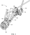
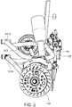
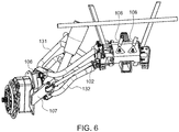
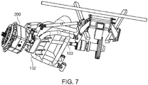
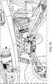
- steering and suspension assembly 100 comprises:
- the first suspension component is an A-arm 121.
- the first steering component is a tie rod 122.
- the steering and suspension assembly further includes a hydraulic fluid line 108 for providing hydraulic power sufficient to cause said first steering component to move a distance effective to turn the vehicle at least 2° in either direction.
- the illustrated hydraulic fluid line provides hydraulic power to a steering component tie rod.
- the assembly further includes a second suspension component 123, and a second suspension connection bracket 124 for connecting the second suspension component to the wheel hub assembly.
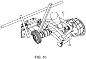
- the first suspension component is an upper A-arm 131
- the second suspension component is a lower A-arm 132.
- the assembly further includes a shock absorbing strut 141.
- the illustrated steering and suspension assembly is preferably effective for moving the first steering component a distance effective to turn the vehicle at least 6° in either direction when the assembly is mounted to a wheel hub.
- the hydraulic steering assembly is effective for moving the first steering component a distance effective to turn the vehicle at least 10° in either direction when the assembly is mounted to a wheel hub.
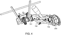
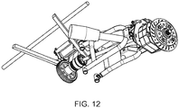
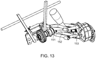
- the illustrated CV axle comprises an inner CV joint 151 adapted to allow the vehicle's drive shaft to transmit power through a variable angle, at constant rotational speed, from the vehicle's drive shaft to the central axle portion 152 of the CV axle.
- the illustrated CV axle comprises an outer CV joint 153 adapted to transmit power through a variable angle, at constant rotational speed, from the central axle portion of the CV axle to the wheel hub assembly.
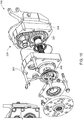
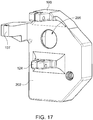
- FIGS. 16 and 17 show more detail about the portal gear box that may be used to provide a wheel hub assembly 104 for mounting a wheel, directly or indirectly, to the CV axle.
- wheel hub assembly may comprise a portal box assembly 200.
- the illustrated portal box assembly 200 comprises:
- Fig. 17 shows an embodiment in which the first suspension connection bracket 106, the second suspension connection bracket 124, and the first steering connection bracket 107 are made integral with the rear wall of the backing plate.
- mounting brackets as being "integral" with the rear wall means that the brackets and rear wall are formed as a unit, and are not distinct parts, as would be the case with a traditional portal box-plus-backing plate construction. Accordingly, the backing plates used in prior art portal box assemblies are unnecessary, and are thus avoided.
- This use of a single piece to cover the rear portion of the portal box and to provide a structure for mounting the suspension to the box provides benefits in strength and structural integrity that are not provided by prior art, two-piece constructions.
- the integral brackets are preferably machined into the metal used to form the rear wall of the portal box, as opposed to being bolted on as would be the case if the brackets were made of sheet steel as prior art mounting brackets are.
- the rear wall/mounting bracket component may be forged, or cast, or otherwise made as a single piece of material.
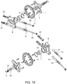
- FIG. 18 shows an exploded view of one embodiment of a wheel hub assembly that may be used in the steering and suspension assembly of the present invention, particularly when a portal gear box is not being used. It is to be appreciated that other forms of wheel hub assemblies may additionally or alternatively be used.
- FIG. 19 shows a perspective view of one embodiment of a CV axle used in the steering and suspension assembly of the present invention.
- Inner CV joint 151, central axle portion 152, and outer CV joint 153 are shown.
- the assembly includes a centering system effective to assist with centering the steering of the vehicle.
- the centering system may detect the direction that the rear wheels are being steered, and in particular may detect the variance from straight/center that the rear wheels are being steered, and may assist in returning the rear-wheel steering to its straight and centered position.
- the centering system may include a linear variable inductance transducer (LVIT) adapted to change length according to the direction of travel of the rear wheels of the vehicle.
- the change in LVIT length or position may be outputted to a controller.
- the LVIT allows the system to know the direction of travel of the rear wheels of the vehicle.
- the centering system may also preferably include a Hall effect sensor that outputs a signal to a driver feedback module and trigger signals to a pump solenoid.
- a Hall effect sensor measures the magnitude of a magnetic field, and its output voltage is directly proportional to the magnetic field strength through it.
- the centering system works through the hydraulic cylinder of the hydraulic steering assembly of the present invention.
- the hydraulic steering assembly uses a push-rod to move the steering connection bracket closer to, or farther from, the vehicle frame, and thus to turn the wheel left or right.
- the first steering component is a tie rod.
- a hydraulic steering box preferably has hydraulic fluid lines to provide the hydraulics needed to move the piston in either direction (out or in) to push or pull the wheel hub, and thus to steer the vehicle.
- upper and lower pivot blocks are used to accommodate rear steering utilizing ball joints.
- a pump may be used to provide hydraulic pressure to the hydraulic cylinder.
- the hydraulic cylinder may be a double acting, double ended hydraulic cylinder to allow pressure to be applied in either of two directions. Accordingly the hydraulic cylinder may cause the controlled wheel(s) to be turned wither to the left or to the right, according to the motion applied to a steering wheel and transmitted to the cylinder.
- the hydraulic steering assembly is preferably controlled by an electronic steering control system that coordinates with the front-wheel steering to provide the appropriate amount of turn in relation to movement of a steering wheel or other steering mechanism.
- a microprocessor with software that collects data from the LVIT and Hall Effect Sensor may be used.
- the microprocessor may output various signals (e.g., LED signals) to a driver feedback module and trigger signals to the pump solenoid.
- a driver feedback module may also be included.
- an LED cluster may be used to give system feedback such as: cylinder position; program mode; auto/manual selector and setting; power indicator; tire size selection; and error codes as needed.
- the present invention may comprise or consist essentially of any or all of the described or illustrated features.
- the present invention includes devices and methods comprising any or all of the features described or illustrated in specification or drawings, and the present invention includes devices and methods consisting essentially of any or all of the features illustrated in the specification or drawings.
- any or all of the features and/or embodiments disclosed herein may be combined with any or all of the other features and/or embodiments disclosed herein to provide a device or method that comprises or consists essentially of such features.
- the grammatical device "and/or" (such as in “A and/or B”) is used in this disclosure to mean A alone, or B alone, or both A and B.
Landscapes
- Engineering & Computer Science (AREA)
- Mechanical Engineering (AREA)
- Chemical & Material Sciences (AREA)
- Combustion & Propulsion (AREA)
- Transportation (AREA)
- Physics & Mathematics (AREA)
- General Physics & Mathematics (AREA)
- General Engineering & Computer Science (AREA)
- Power Engineering (AREA)
- Steering-Linkage Mechanisms And Four-Wheel Steering (AREA)
- Vehicle Body Suspensions (AREA)
Applications Claiming Priority (1)
| Application Number | Priority Date | Filing Date | Title |
|---|---|---|---|
| US201962898592P | 2019-09-11 | 2019-09-11 |
Publications (1)
| Publication Number | Publication Date |
|---|---|
| EP3792086A1 true EP3792086A1 (de) | 2021-03-17 |
Family
ID=72474127
Family Applications (1)
| Application Number | Title | Priority Date | Filing Date |
|---|---|---|---|
| EP20195784.2A Withdrawn EP3792086A1 (de) | 2019-09-11 | 2020-09-11 | Lenk- und montagesystem am hinteren ende |
Country Status (3)
| Country | Link |
|---|---|
| US (2) | US11731691B2 (de) |
| EP (1) | EP3792086A1 (de) |
| CA (1) | CA3093938A1 (de) |
Families Citing this family (5)
| Publication number | Priority date | Publication date | Assignee | Title |
|---|---|---|---|---|
| US20210276383A1 (en) * | 2020-03-09 | 2021-09-09 | Robby Gordon | Leading-edge front suspension |
| US11376910B1 (en) * | 2021-03-12 | 2022-07-05 | Kawasaki Motors, Ltd. | Suspension structure of utility vehicle |
| US12065034B2 (en) * | 2021-05-24 | 2024-08-20 | Robby Gordon | Rear portal gear assembly for trailing arms |
| US12350994B2 (en) * | 2022-12-28 | 2025-07-08 | Kawasaki Motors, Ltd. | Suspension and off-road vehicle |
| WO2026018258A1 (en) * | 2024-07-19 | 2026-01-22 | Ve Commercial Vehicles Ltd. | Steerable hub for small commercial vehicle |
Citations (4)
| Publication number | Priority date | Publication date | Assignee | Title |
|---|---|---|---|---|
| EP0463309A1 (de) * | 1990-06-28 | 1992-01-02 | Bayerische Motoren Werke Aktiengesellschaft | Verfahren zum Betrieb einer Lenkeinrichtung für die Hinterräder eines Kraftfahrzeugs |
| US6625529B2 (en) * | 2001-06-14 | 2003-09-23 | Nissan Motor Co., Ltd. | Apparatus for controlling steering angles of front rear wheels of vehicle |
| WO2010020607A1 (en) * | 2008-08-22 | 2010-02-25 | Agco Netherlands B.V. | Suspension for an agricultural machine |
| DE102017111785A1 (de) * | 2017-05-30 | 2018-12-06 | Horsch Leeb Application Systems Gmbh | Portalgetriebe |
Family Cites Families (63)
| Publication number | Priority date | Publication date | Assignee | Title |
|---|---|---|---|---|
| US1396102A (en) * | 1919-06-16 | 1921-11-08 | Militor Corp | Axle construction for motor-vehicles |
| US1974036A (en) * | 1934-04-06 | 1934-09-18 | Ammen Francis Du Pont | Easy parking automobile |
| FR2240678B1 (de) * | 1973-08-14 | 1978-01-13 | Fahr Ag Maschf | |
| US3983951A (en) * | 1975-10-22 | 1976-10-05 | Imeldo Rodriguez Guerra | Front end drive mounting |
| US4372407A (en) * | 1978-08-17 | 1983-02-08 | Owens-Illinois, Inc. | Independent steering and propulsion system for off road vehicle |
| JPS5711173A (en) * | 1980-06-24 | 1982-01-20 | Nissan Motor Co Ltd | Method of controlling steering angle for vehicle capable of steering two sets of wheels |
| US4344501A (en) * | 1980-08-18 | 1982-08-17 | Gearco Limited | Geared hub |
| JPS60161265A (ja) * | 1984-01-31 | 1985-08-22 | Nissan Motor Co Ltd | 車両の操舵方法 |
| JPH0674052B2 (ja) * | 1984-01-31 | 1994-09-21 | 日産自動車株式会社 | 車両の操舵方法 |
| JPS62113652A (ja) * | 1985-11-13 | 1987-05-25 | Nissan Motor Co Ltd | 4輪操舵車両 |
| JP2513699B2 (ja) * | 1987-06-26 | 1996-07-03 | 日産自動車株式会社 | リヤサスペンシヨン |
| JP2534730B2 (ja) * | 1987-09-29 | 1996-09-18 | 日産自動車株式会社 | 4輪操舵・差動制限力総合制御装置 |
| JPH0211479A (ja) * | 1988-06-29 | 1990-01-16 | Toyota Motor Corp | 前後輪操舵車の後輪操舵制御装置 |
| US4949984A (en) * | 1988-07-25 | 1990-08-21 | Mazda Motor Corporation | Rear-wheel steering apparatus for vehicle |
| US5020627A (en) | 1989-04-21 | 1991-06-04 | Wittke Rudolph H | Four-wheel drive tractor |
| JPH0392483A (ja) * | 1989-09-04 | 1991-04-17 | Nissan Motor Co Ltd | 後輪操舵制御装置 |
| JPH0481363A (ja) * | 1990-07-20 | 1992-03-16 | Toyota Motor Corp | 四輪操舵車の後輪操舵制御装置 |
| US5194851A (en) * | 1991-02-21 | 1993-03-16 | Case Corporation | Steering controller |
| US5174595A (en) * | 1991-07-17 | 1992-12-29 | Deere & Company | Four wheel steering mechanism |
| US5402341A (en) * | 1992-04-06 | 1995-03-28 | Ford Motor Company | Method and apparatus for four wheel steering control utilizing tire characteristics |
| US5734570A (en) * | 1992-08-04 | 1998-03-31 | Lotus Cars Limited | Wheeled vehicle steering system for steering the rear wheels of a vehicle |
| US5288091A (en) * | 1993-01-29 | 1994-02-22 | Noma Outdoor Products, Inc. | Four wheel steering apparatus |
| US5845926A (en) * | 1997-01-21 | 1998-12-08 | Ford Global Technologies, Inc. | Independent suspension apparatus for a wheeled vehicle |
| EP1144237A4 (de) * | 1998-12-04 | 2003-03-12 | Mts System Corp | Apparat zum testen einer mehrfachlenkanlage |
| US6131689A (en) * | 1998-12-11 | 2000-10-17 | Deere & Company | All-wheel-steer biasing mechanism |
| RU2163209C1 (ru) | 1999-05-24 | 2001-02-20 | Писаревский Виктор Михайлович | Тяговое транспортное средство (варианты) |
| US6523632B1 (en) * | 1999-07-15 | 2003-02-25 | Honda Giken Kogyo Kabushiki Kaisha | Vehicle equipped with turning mechanism |
| US6292094B1 (en) * | 2001-01-16 | 2001-09-18 | General Motors Corporation | Vehicle-trailer backing-up control system with vehicle rear wheel steering |
| US6722994B2 (en) * | 2001-03-09 | 2004-04-20 | Deer & Co. | Suspended drive axle and agricultural tractor with same |
| US6684974B1 (en) * | 2002-07-24 | 2004-02-03 | Deere & Company | Four-wheel steering system for utility vehicle |
| US7377522B2 (en) * | 2002-09-18 | 2008-05-27 | Macisaac William L | Vehicle with movable and inwardly tilting safety body |
| US7316288B1 (en) * | 2003-01-27 | 2008-01-08 | Polaris Industries Inc. | All terrain vehicle with multiple steering modes |
| US7073620B2 (en) * | 2003-06-06 | 2006-07-11 | Oshkosh Truck Corporation | Vehicle steering system having a rear steering control mechanism |
| US6761234B1 (en) * | 2003-06-26 | 2004-07-13 | Case, Llc | Skid steer vehicle with steerable suspension |
| US8380416B2 (en) * | 2004-03-18 | 2013-02-19 | Ford Global Technologies | Method and apparatus for controlling brake-steer in an automotive vehicle in reverse |
| JP4424104B2 (ja) * | 2004-07-15 | 2010-03-03 | 日産自動車株式会社 | 車輪独立懸架装置 |
| US7347434B2 (en) * | 2004-07-20 | 2008-03-25 | Briggs & Stratton Corporation | Four-wheel steering assembly |
| US7249418B2 (en) | 2004-11-12 | 2007-07-31 | Hella KG a.A. Hueck & Co. | Wheel position sensor |
| US8833504B2 (en) * | 2005-12-02 | 2014-09-16 | Trw Automotive U.S. Llc | Steering apparatus |
| JP2010208619A (ja) * | 2009-02-10 | 2010-09-24 | Honda Motor Co Ltd | 車両挙動制御装置 |
| US8485543B2 (en) | 2009-04-29 | 2013-07-16 | Reyco Granning, Llc | Independent suspension and steering assembly |
| DE102011007283A1 (de) | 2011-04-13 | 2012-10-18 | Bayerische Motoren Werke Aktiengesellschaft | Fahrzeug-Einzelradaufhängung für ein geringfügig lenkbares Hinterrad eines zweispurigen Fahrzeugs |
| US8925941B2 (en) * | 2011-10-13 | 2015-01-06 | Axletech International Ip Holdings, Llc | Modular independent suspension and method of producing the same |
| US8651223B2 (en) * | 2011-10-28 | 2014-02-18 | Deere & Company | Synchronizing system for hydraulic four wheel steering |
| US8886410B2 (en) * | 2013-02-13 | 2014-11-11 | Honda Motor Co., Ltd. | Methods of controlling four-wheel steered vehicles |
| US20150101876A1 (en) * | 2013-10-16 | 2015-04-16 | SXS Gear, LLC | Portal box |
| WO2015114604A1 (en) * | 2014-01-31 | 2015-08-06 | Bombardier Recreational Products Inc. | Off-road wheeled side-by-side vehicle |
| US9439341B2 (en) * | 2014-08-08 | 2016-09-13 | Deere & Company | Multi-mode steering control for a vehicle |
| US10479156B2 (en) * | 2015-10-02 | 2019-11-19 | Super ATV, LLC | Forged portal hub mounting body |
| US10527130B2 (en) * | 2016-09-30 | 2020-01-07 | Grant Shirley | Gear lift box assembly |
| US20180250998A1 (en) * | 2016-12-30 | 2018-09-06 | Axel Michael Sigmar | Wheel Module with Integrated Active Suspension |
| DE102017106810A1 (de) * | 2017-03-29 | 2018-10-04 | Emm! Solutions Gmbh | Radaufhängung |
| DE112017000027T5 (de) * | 2017-04-28 | 2018-12-27 | Komatsu Ltd. | Anzeigevorrichtung und arbeitsfahrzeug |
| US10532629B2 (en) * | 2017-09-06 | 2020-01-14 | Ford Global Technologies, Llc | Radiant heating system incorporating steering wheel position monitoring device |
| US11161544B2 (en) * | 2018-05-31 | 2021-11-02 | Bombardier Recreational Products Inc. | Rear steering assembly for a vehicle |
| CA3044749C (en) * | 2018-05-31 | 2025-08-05 | Bombardier Recreational Products Inc. | REAR STEERING ASSEMBLY INTENDED FOR A VEHICLE |
| US11420677B2 (en) * | 2018-10-24 | 2022-08-23 | Agco Corporation | Mounting assembly for a steerable wheel with variable track width |
| US11554662B2 (en) * | 2019-01-21 | 2023-01-17 | Super ATV, LLC | Assembly for mounting a wheel to a portal gear box of an off-road vehicle |
| DE102020105378A1 (de) * | 2020-02-28 | 2021-09-02 | Horsch Leeb Application Systems Gmbh | Lenkbare Einzelradaufhängung mit zusätzlichem Träger |
| US11364759B1 (en) * | 2020-04-27 | 2022-06-21 | High Lifter Products Inc. | Adjustable vehicle suspension link system and methods |
| KR102948421B1 (ko) * | 2020-06-08 | 2026-04-06 | 현대자동차주식회사 | 이동체 |
| US20210402875A1 (en) * | 2020-06-25 | 2021-12-30 | Xuan Chieu Pham | Automobile with Extended 90-Degree Steering Range for Parallel Parking or Other Uses |
| US11414127B2 (en) * | 2020-06-30 | 2022-08-16 | Zoox, Inc. | Trajectory tracking with four-wheel steering |
-
2020
- 2020-09-10 US US17/016,803 patent/US11731691B2/en active Active
- 2020-09-11 CA CA3093938A patent/CA3093938A1/en active Pending
- 2020-09-11 EP EP20195784.2A patent/EP3792086A1/de not_active Withdrawn
-
2023
- 2023-08-21 US US18/452,993 patent/US20230391396A1/en active Pending
Patent Citations (4)
| Publication number | Priority date | Publication date | Assignee | Title |
|---|---|---|---|---|
| EP0463309A1 (de) * | 1990-06-28 | 1992-01-02 | Bayerische Motoren Werke Aktiengesellschaft | Verfahren zum Betrieb einer Lenkeinrichtung für die Hinterräder eines Kraftfahrzeugs |
| US6625529B2 (en) * | 2001-06-14 | 2003-09-23 | Nissan Motor Co., Ltd. | Apparatus for controlling steering angles of front rear wheels of vehicle |
| WO2010020607A1 (en) * | 2008-08-22 | 2010-02-25 | Agco Netherlands B.V. | Suspension for an agricultural machine |
| DE102017111785A1 (de) * | 2017-05-30 | 2018-12-06 | Horsch Leeb Application Systems Gmbh | Portalgetriebe |
Also Published As
| Publication number | Publication date |
|---|---|
| CA3093938A1 (en) | 2021-03-11 |
| US20210070354A1 (en) | 2021-03-11 |
| US11731691B2 (en) | 2023-08-22 |
| US20230391396A1 (en) | 2023-12-07 |
Similar Documents
| Publication | Publication Date | Title |
|---|---|---|
| US20230391396A1 (en) | Rear end steering and mounting system | |
| EP2944540B1 (de) | Drehsystem und schwerlastradfahrzeug mit unabhängiger aufhängung | |
| CN112026910A (zh) | 一种运用于无人驾驶的全自由度转向的线控底盘平台 | |
| EP1534575B1 (de) | Fahrzeug, verfahren und lenksystem für ein fahrzeug | |
| US5154437A (en) | Vehicle steering system with independent steering for each wheel | |
| CN110949498B (zh) | 一种电动汽车和集成转向与悬架的轮毂结构 | |
| US12208676B2 (en) | One-piece portal wheel end mounting system | |
| US4418783A (en) | Tractor | |
| JPS63162313A (ja) | 自動車のサスペンシヨン装置 | |
| US5934404A (en) | Rack and pinion steering system for solid front axle | |
| CN213323321U (zh) | 一种运用于无人驾驶的全自由度转向的线控底盘平台 | |
| WO2015097483A1 (en) | An axle assembly, a steering mechanism, a vehicle, and a trailer | |
| US9776495B2 (en) | Active mounting system for vehicle transfer case | |
| CN219634908U (zh) | 一种四轮驱动四轮转向底盘及车辆 | |
| GB2414454A (en) | Adjustable steering limit | |
| Murali et al. | Design and Development of Four-Wheel Steering for All Terrain Vehicle (ATV) | |
| KR100447747B1 (ko) | 차량용 조향장치 | |
| JP3585285B2 (ja) | 駆動操向車輪の支持部構造 | |
| RU2743346C1 (ru) | Колесный блок с управляемой подвеской | |
| JPH0631005B2 (ja) | 後2軸車の後軸操舵装置 | |
| JP4941722B2 (ja) | 車両用操舵装置 | |
| JPH0645416Y2 (ja) | クレ−ン車の操舵装置 | |
| KR200200480Y1 (ko) | 스키드 로더 | |
| Zadafiya et al. | Developing a System for Reducing the Turning Radius of a Car | |
| JPH0355450Y2 (de) |
Legal Events
| Date | Code | Title | Description |
|---|---|---|---|
| PUAI | Public reference made under article 153(3) epc to a published international application that has entered the european phase |
Free format text: ORIGINAL CODE: 0009012 |
|
| STAA | Information on the status of an ep patent application or granted ep patent |
Free format text: STATUS: THE APPLICATION HAS BEEN PUBLISHED |
|
| AK | Designated contracting states |
Kind code of ref document: A1 Designated state(s): AL AT BE BG CH CY CZ DE DK EE ES FI FR GB GR HR HU IE IS IT LI LT LU LV MC MK MT NL NO PL PT RO RS SE SI SK SM TR |
|
| AX | Request for extension of the european patent |
Extension state: BA ME |
|
| STAA | Information on the status of an ep patent application or granted ep patent |
Free format text: STATUS: REQUEST FOR EXAMINATION WAS MADE |
|
| 17P | Request for examination filed |
Effective date: 20210917 |
|
| RBV | Designated contracting states (corrected) |
Designated state(s): AL AT BE BG CH CY CZ DE DK EE ES FI FR GB GR HR HU IE IS IT LI LT LU LV MC MK MT NL NO PL PT RO RS SE SI SK SM TR |
|
| STAA | Information on the status of an ep patent application or granted ep patent |
Free format text: STATUS: EXAMINATION IS IN PROGRESS |
|
| 17Q | First examination report despatched |
Effective date: 20230828 |
|
| STAA | Information on the status of an ep patent application or granted ep patent |
Free format text: STATUS: THE APPLICATION IS DEEMED TO BE WITHDRAWN |
|
| 18D | Application deemed to be withdrawn |
Effective date: 20250401 |