EP3792199B1 - Endrahmenstruktur und tankartiger behälter damit - Google Patents
Endrahmenstruktur und tankartiger behälter damit Download PDFInfo
- Publication number
- EP3792199B1 EP3792199B1 EP19799338.9A EP19799338A EP3792199B1 EP 3792199 B1 EP3792199 B1 EP 3792199B1 EP 19799338 A EP19799338 A EP 19799338A EP 3792199 B1 EP3792199 B1 EP 3792199B1
- Authority
- EP
- European Patent Office
- Prior art keywords
- corner
- end frame
- tank body
- tank
- castings
- Prior art date
- Legal status (The legal status is an assumption and is not a legal conclusion. Google has not performed a legal analysis and makes no representation as to the accuracy of the status listed.)
- Active
Links
Images



Classifications
-
- B—PERFORMING OPERATIONS; TRANSPORTING
- B65—CONVEYING; PACKING; STORING; HANDLING THIN OR FILAMENTARY MATERIAL
- B65D—CONTAINERS FOR STORAGE OR TRANSPORT OF ARTICLES OR MATERIALS, e.g. BAGS, BARRELS, BOTTLES, BOXES, CANS, CARTONS, CRATES, DRUMS, JARS, TANKS, HOPPERS, FORWARDING CONTAINERS; ACCESSORIES, CLOSURES, OR FITTINGS THEREFOR; PACKAGING ELEMENTS; PACKAGES
- B65D88/00—Large containers
- B65D88/02—Large containers rigid
- B65D88/12—Large containers rigid specially adapted for transport
- B65D88/128—Large containers rigid specially adapted for transport tank containers, i.e. containers provided with supporting devices for handling
-
- B—PERFORMING OPERATIONS; TRANSPORTING
- B65—CONVEYING; PACKING; STORING; HANDLING THIN OR FILAMENTARY MATERIAL
- B65D—CONTAINERS FOR STORAGE OR TRANSPORT OF ARTICLES OR MATERIALS, e.g. BAGS, BARRELS, BOTTLES, BOXES, CANS, CARTONS, CRATES, DRUMS, JARS, TANKS, HOPPERS, FORWARDING CONTAINERS; ACCESSORIES, CLOSURES, OR FITTINGS THEREFOR; PACKAGING ELEMENTS; PACKAGES
- B65D90/00—Component parts, details or accessories for large containers
- B65D90/12—Supports
- B65D90/20—Frames or nets, e.g. for flexible containers
Definitions
- a tank container usually includes a frame and a tank body supported by the frame.
- the frame protects and hoists the tank body.
- the frame usually includes a front end frame, a rear end frame and a beam connecting the front end frame and the rear end frame.
- swap body tank containers are often large volume tank containers.
- the traditional end frame structure hardly meets these strength requirements.
- CN103043328A discloses a large volume tank container which comprises a tank, front and rear frames, upper and lower side beams, an operating platform and a ladder.
- the large volume tank container is characterized in that a reinforcing ring is arranged on the surface of the tank.
- the tank is connected with the front and rear frames through webs.
- Front and rear support legs are arranged at the bottoms of the front and rear frames respectively.
- a bottom discharge system is disposed at the rear bottom of the tank and has a tilting angle of 30-45 degree.
- the tank container comprises a frame and a tank body.
- the frame comprises two end frames which are arranged oppositely.
- Each end frame comprises a corner piece, two corner columns, an end upper beam and an end lower beam.
- the corner column surfaces, facing each other, of each of the two end frames are inner end faces.
- the corner piece surfaces, backing onto each other, of each of the two end frames are outer end faces.
- the tank body is arranged in the frame and comprises a cylinder and two end sockets, wherein the two ends of the cylinder are through, the two end sockets are connected to the two ends of the cylinder respectively, and a confined space is defined by the end sockets and the cylinder.
- the end face of at least one end of the cylinder stretches into the end frame close to the end face, so that the end face is made to be located between the corresponding inner end face and the corresponding outer end face.
- the end socket of the end, stretching into the corresponding end frame, of the cylinder is located between the corresponding inner end face and the corresponding outer end face.
- EP3395721A1 discloses a tank container for the storage and/or transport of gas and/or liquid.
- the tank container comprising a frame and an elongated and essentially cylindrical tank vessel comprising two head-ends, said frame comprising at each head-end an associated head-end frame with at least two bottom corner fittings and an associated head-end saddle support; in which at each head-end said head-end frame and said head-end saddle support are mutually connected by two associated transfer beams, in which each transfer beam comprises a beam which, near one of said bottom corner fittings, connects the head-end frame to the associated head-end saddle support; in which said transfer beam further comprises a gusset which is permanently connected to said beam and which, viewed away from the associated head-end frame, extends over a distance of A1 beyond the associated head-end saddle support, in which said distance A1 is at least 200 mm, preferably at least 400 mm.
- the present invention provides tank container and end frame structure thereof, in accordance with claims which follow.
- the present invention is to provide an end frame structure with higher strength.
- a end frame structure of a tank container comprises a top rail, a bottom rail, two corner posts, two top corner castings disposed at the top of the two corner posts and two bottom corner castings disposed at the bottom of the two corner posts, both ends of the top rail connected to the two top corner castings respectively, both ends of the bottom rail connected to the two bottom corner castings respectively, wherein each corner post includes a body and a reinforcing part, the reinforcing part and the body configured to be disposed in parallel along the axial direction of a tank body, the body adapted with the reinforcing part to form a tubular structure.
- the width of the reinforcing part along the axial direction of the tank body is the same, or the width of the reinforcing part along the axial direction of the tank body increases gradually from the upper end and the lower end to the middle.
- the reinforcing part and the body are of an integral structure.
- the distance between the inner lateral surfaces of the two corner posts is greater than or equal to the distance between the two top corner castings or the two bottom corner castings.
- the inner lateral surface of the corner post is provided with an arc-shaped groove adapted with the tank body.
- an escape groove is disposed on the bottom rail, and the bottom rail is provided with a connecting block above the escape groove.
- a connecting plate provided with a through hole for allowing the tank body to pass through, wherein a frame is formed by the two corner posts jointing with the top rail and the bottom rail, and the connecting plate is connected to and covers the frame from at least one side of the frame.
- the connecting plates are disposed on the front side and the back side of the frame, and a reinforcing plate is disposed vertically between two connecting plates, the reinforcing plate extends from the top corner castings or the bottom corner castings to the through hole.
- the top corner castings and the bottom corner castings are made by casting, and the yield strength of the top corner castings and the bottom corner castings is greater than or equal to 420 MPa.
- the present invention also provides a tank container.
- the tank container comprises a tank body and the above described end frame structures, the end frame structures disposed at both ends of the tank body, the both ends of the tank body fixed by the end frame structures, the both ends of the tank body provided with seal heads, the seal heads passing through the end frame structures respectively.
- the reinforcing part and the body are disposed in parallel along the axial direction of the tank body by designing the shape of the corner posts.
- the corner posts are provided with the reinforcing parts to increase the width, so as to enhance the strength of the corner posts, so that the load of the end frame structure can meet the requirement of 78 tons.
- the distance between the two bodies is greater than the distance between the two top corner castings or the distance between the two corner castings.
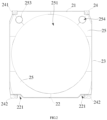
- end frame structure 20. frame; 21. top rail; 22. bottom rail; 221. escape groove; 222. connecting blocks; 223. cut surface; 224. arc surface; 23. corner post; 231. body; 232. reinforcing part; 233. inclined surface; 234. arc-shaped groove; 235. inner lateral surface; 236. outer lateral surface; 24. corner casting; 241. top corner casting; 242. bottom corner casting; 25. connecting plate; 251. through hole; 252. reinforcing plate; 253. reinforcing tube; 254. hole; 26. hoisting protection plate; 3. cross beam.
- the indications of the direction(such as up, down, left, right, front, and back) that are used to explain the structure and movement of the various elements of the present invention are not absolutely, but relatively. These illustrations are appropriate when these elements are in the positions shown in the figures. If the description of the positions of these elements is changed, the indications of these directions are changes accordingly.
- the present invention proposes a tank container and an end frame structure thereof.
- the tank container of this embodiment includes a tank body and end frame structures 2 provided at both ends of the tank body. Both ends of the tank body are fixed by the end frame structure 2, and the both ends of the tank body are provided with seal heads.
- the seal heads pass through the two end frame structures 2 respectively.
- the end of the tank body close to the head of a vehicle is called the front end
- the other end of the tank body is the rear end. Therefore, the two end frame structures 2 are a front end frame and a rear end frame, respectively.
- the two ends of the tank body are respectively fixed by the front end frame and the rear end frame, and the seal heads pass through the front end frame and the rear end frame, respectively.
- the tank body is a large volume tank body.
- the distance between the front end frame and the rear end frame is 9.144 m or 12.192 m.
- the end frame structure 2 includes a top rail 21, a bottom rail 22, two corner posts 23 and four corner castings 24.
- the corner casting 24 includes two top corner castings 241 provided at the top ends of the two corner posts 23 and bottom corner castings 242 provided at the bottom ends of the two corner posts 23. Both ends of the top rail 21 are respectively connected to two top corner castings 241, and both ends of the bottom rail 22 are respectively connected to two bottom corner castings 242.
- the top corner casting 241 and the bottom corner casting 242 are castings.
- the yield strength of the top corner castings 241 and the bottom corner castings 242 is greater than or equal to 420 MPa, so as to meet the need of the transporting large volume tank body.
- the distance between the two top corner castings 241 is 2438 mm, and the distance between the two bottom corner castings 242 is less than or equal to 2600 mm, so as to ensure that the hole of the corner casting can be adapted to a lock which is disposed on a transport device of the rail, road, and shipping. It can be understood that the distance between the two top corner castings 241 may also be the same as the distance between the two bottom corner castings 242, as long as the transportation requirements of that the corner casting is able to match with the lock could be met.
- the top rail 21 and the bottom rail 22 are oppositely disposed.
- the top rail 21 and the bottom rail 22 are tubular structures, for example, square tubes or round tubes.
- a hoisting protection plate 26 is provided at the joints between the top rail 21 and the top corner casting 241.
- the hoisting protection plate 26 is triangular.
- the hoisting protection plate 26 connects the top rail 21 with a cross beam 3 between the both end frame structures 2.
- the hoisting protection plate can strengthen the joints of the top rail 21, the top corner casting 241 and the crossbeam 3, and prevent damage during the hoisting process.
- the bottom rail 22 is provided with an escape groove 221.
- the escape groove 221 is used to avoid a fixed lock on the vehicle frame and the like.
- the bottom rail 22 is provided with a connecting block 222 above the escape groove 221.
- the connecting block 222 connects the bottom rail 22 with the bottom corner casting 242.
- the connecting block 222 can strengthen the strength of the bottom rail 22 and the escape groove 221, so as to prevent the bottom rail 22 from affecting the overall strength of the bottom rail 22 due to the setting of the escape groove 221.
- the width of the connecting block 222 is equal to the width of the bottom rail 22.
- One end of the connecting block 222 is in contact with the inner lateral surface 235 of the corner post 23.
- the other end of the connecting block 222 is provided with a cut surface 223.
- the cut surface 223 is adapted to the outer surface of the tank body. It can be understood that the connecting block 222 is a rectangular square tube.
- the length of the bottom rail 22 is smaller than the distance between the two bottom corner castings 242. Therefore, the escape groove 221 is formed by the end surface of the bottom rail 22 and the side surface of the bottom corner casting 242.
- the bottom rail 22 is provided with an arc surface 224, which is adapted to the surface of the tank body.
- the arc surface 224 can better fix and support the tank body.
- a frame 20 is formed by the two corner posts 23 jointing with the top rail 21 and the bottom rail 22 through the corner castings 24
- the side of the corner post 23 facing the inner lateral surface of the frame 20 is the inner lateral surface235 of the corner post 23, the side that is opposed to the inner lateral surface 235 is the outer lateral surface 236 of the corner post 23.
- the corner post 23 includes a body 231 and a reinforcing part 232.
- the body 231 and the reinforcing part 232 are disposed in parallel along the axial direction of the tank body, and the reinforcing part 232 is adapted to the body 231 to form a tubular structure.
- the body 231 and the reinforcing part 232 are spliced into the corner post 23 of tubular shape.
- the width of the reinforcing part 232 along the axial direction of the tank body is the same.
- the cross-sectional area of the middle portion of the reinforcing part 232 is equal to the cross-sectional area of both ends of the reinforcing part 232.
- the cross-sectional area of the middle portion of the reinforcing part 232 is equal to the cross-sectional area of both ends.
- the width of the corner post 23 along the axial direction of the tank body is the same. That is, the corner post 23 is a rectangular square tube.
- the body 231 and the reinforcing part 232 are steels with a square groove.
- the reinforcing part 232 reinforces the strength of the corner post 23 from the side of the body 231.
- the reinforcing part 232 and the body 231 are integral structures.
- the reinforcing part 232 widens the end surface of the corner post 23 along the axial direction of the tank body, increases the connection area between the corner post 23 and the corner casting 24, and strengthens the connection strength between the corner post 23 and the corner casting 24.
- the corner post 23 is composed of the body 231 and the reinforcing part 232, the length of the corner post 23 is relatively large along the axial direction of the tank body and the length of the corner post 23 is relatively small in the direction perpendicular to the axial direction of the tank body. Therefore, the corner post 23 can be connected to the outer portion of the corner casting 24, so that the distance between the inner lateral surfaces 235 of the two corner posts 23 can be increased.
- the distance between the inner lateral surfaces 235 of the two corner posts 23 is greater than the distance between the two top corner castings 241 or the two bottom corner castings 242. Therefore, without affecting the hoisting and transportation of the entire tank container, the distance between the two corner posts 23 is increased, so that the end frame structure 2 can fix a larger volume tank body.
- the outer lateral surfaces 236 of both ends of the corner post 23 are provided with inclined surfaces 233.
- the inclined surface 233 is bent toward the inner lateral surface 235 of the corner post 23, and the angle between the inclined surface 233 and the inner lateral surface 235 of the corner post 23 is an acute angle.
- the area of the cross section of the both ends of the corner post 23 gradually decreases along the height direction, ensuring that both ends of the corner post 23 can be connected to the corner casting 24.
- the width of the reinforcing part 232 in the axial direction of the tank body increases from the upper end and the lower end to the middle.
- the cross-sectional area of the middle portion of the reinforcing part 232 is larger than the cross-sectional area of both ends of the reinforcing part 232.
- the width of the corner post 23 in the axial direction of the tank body increases from both ends to the middle. In the axial direction of the tank body, the width of the central portion of the corner post 23 is increasing with respect to the widths of the both ends, which can enhance the strength of the corner post 23.
- corner post 23 may also be formed by splicing a special-shaped square tube, square tube or round tube, or a plate with each other.
- the corner post 23 maximizes the distance between the two corner posts 23, so that the end frame structure 2 can fix a larger volume tank body.
- the inner lateral surface 235 of the corner post 23 is provided with an arc-shaped groove 234 adapted to the tank body.
- the two arc-shaped grooves 234 can further expand the distance between the inner lateral surfaces 235 of the two corner posts 23, so that the end frame structure 2 can fix a larger volume tank body; on the other hand, the arc-shaped grooves 234 enable the corner posts 23 to clamp the tank body to enhance the stability of the connection between the tank body and the end frame structure 2.
- the height of the corner post 23 is less than or equal to 2743 mm, or the height of the corner post is less than or equal to 2896 mm.
- the end frame structure 2 further includes a connecting plate 25.
- the connecting plate 25 covers one side of the frame 20.
- the connecting plate 25 is connected to and covers the frame 20 from at least one side of the frame 20.
- the peripheral edges of the connecting plate 25 are welded to the peripheral edges of the frame 20.
- the connecting plate 25 covers the frame 20 into a box-like structure to enhance the strength of the end frame structure 2.
- the connecting plate 25 is a ribbed plate to improve the strength of the end frame structure 2.
- the shape of the connecting plate 25 is adapted with the shape of the frame 20.
- the connecting plate 25 is provided with a through hole 251 for allowing the tank body to pass through. Moreover, the edge of the through hole 251 is aligned with the arc-shaped surface of the corner post 23. Both ends of the tank body extend from the through hole 251 of the connecting plate 25.
- a reinforcing plate 252 is vertically provided between the two connecting plates 25. The reinforcing plate is located vertically in the box-shaped structure. The reinforcing plate 252 enhances the strength of the box-like structure.
- the reinforcing plate 252 extends from the top corner casting 241 or the bottom corner casting 242 to the through hole 251. There are a plurality of reinforcing plates 252. When hoisting or transporting the tank body, the stress is transferred from the tank body to the corner casting 24 by the reinforcing plate 252 and is released.
- the end frame structure 2 is also provided with a reinforcing tube 253.
- the connecting plate 25 is also provided with a hole 254.
- the reinforcing tube 253 is provided between the two connecting plates 25, and openings at both ends of the reinforcing tube 253 are face to face with the holes 254. The stress of the connecting plate 25 can be released through the hole 254, and the reinforcing tube 253 can enhance the strength of the end frame structure 2.
- connecting plate 25 there is one connecting plate 25.
- the connecting plate 25 may be provided on the front side or the backside of the frame 20.
- the connecting plate 25 is provided inside the frame 20, and the connecting plate 25 is located on the center surface of the frame 20.
- the central surface of the frame 20 is a central section of the frame 20 along the radial direction of the tank body.
- the connecting plate 25 inside the frame 20 reinforces the strength of the end frame structure 2.
- connecting plate 25 may be formed by welding multiple pieces of sheet metal, or may be an integrated structure.
- the width of the corner post 23 is increased in the axial direction of the tank body to strengthen the corner post, so that the load of the end frame structure can meet the requirement of 78 tons.
- the distance between the two bodies is greater than the distance between the two top corner castings or the two bottom corner castings.
- the above-mentioned end frame structure 2 can fix a larger volume tank body without affecting the hoisting and transportation of the entire tank container.
Landscapes
- Engineering & Computer Science (AREA)
- Mechanical Engineering (AREA)
- Details Of Rigid Or Semi-Rigid Containers (AREA)
- Filling Or Discharging Of Gas Storage Vessels (AREA)
- Housings And Mounting Of Transformers (AREA)
- Rigid Containers With Two Or More Constituent Elements (AREA)
Claims (9)
- Endrahmenstruktur (2) für einen Tankcontainer, umfassend: eine obere Schiene (21), eine untere Schiene (22), zwei Eckpfosten (23), zwei obere Eckbeschläge (241), die an der Oberseite an den zwei Eckpfosten (23) angeordnet sind, und zwei untere Eckbeschläge (242), die an der Unterseite an den zwei Eckpfosten (23) angeordnet sind, wobei beide Enden der oberen Schiene (21) jeweils mit den zwei oberen Eckbeschlägen (241) verbunden sind und beide Enden der unteren Schiene (22) jeweils mit den zwei unteren Eckbeschlägen (242) verbunden sind, dadurch gekennzeichnet, dass jeder Eckpfosten (23) einen Körper (231) und ein Verstärkungsteil (232) umfasst, wobei das Verstärkungsteil (232) und der Körper (231) konfiguriert sind, um parallel entlang der axialen Richtung eines Tankkörpers angeordnet zu sein, wobei der Körper (231) mit dem Verstärkungsteil (232) angepasst ist, um eine röhrenförmige Struktur auszubilden, wobei das Verstärkungsteil (232) konfiguriert ist, um die äußere laterale Oberfläche (236) des Eckpfostens (23) entlang der axialen Richtung des Tankkörpers zu verbreitern,was eine Verbindungsfläche zwischen dem Eckpfosten (23) und den Eckbeschlägen (24) vergrößert,und eine Verbindungsfestigkeit zwischen dem Eckpfosten (23) und den Eckbeschlägen (24) verstärkt, wobei die oberen Eckbeschläge (241) und die unteren Eckbeschläge (242) durch ein Gießen hergestellt werden und die Streckgrenze der oberen Eckbeschläge (241) und der unteren Eckbeschläge (242) größer als oder gleich 420 MPa ist.
- Endrahmenstruktur (2) für den Tankcontainer nach Anspruch 1,
dadurch gekennzeichnet, dass die Breite des Verstärkungsteils (232), das konfiguriert ist, um entlang der axialen Richtung des Tankkörpers zu verlaufen, gleich ist oder dass die Breite des Verstärkungsteils (232), das konfiguriert ist, um entlang der axialen Richtung des Tankkörpers zu verlaufen, von dem oberen Ende und dem unteren Ende zu der Mitte hin allmählich zunimmt. - Endrahmenstruktur (2) für den Tankcontainer nach Anspruch 1,
dadurch gekennzeichnet, dass das Verstärkungsteil (232) und der Körper (231) eine integrale Struktur sind. - Endrahmenkonstruktion (2) für Tankcontainer nach Anspruch 1,
dadurch gekennzeichnet, dass der Abstand zwischen den inneren lateralen Oberflächen (235) der zwei Eckpfosten (23) größer als oder gleich dem Abstand zwischen den zwei oberen Eckbeschlägen (241) oder den zwei unteren Eckbeschlägen (242) ist. - Endrahmenstruktur (2) für den Tankcontainer nach Anspruch 1,
dadurch gekennzeichnet, dass die innere laterale Oberfläche (235) jedes Eckpfostens (23) mit einer bogenförmigen Nut (234) versehen ist, die an die Form des Tankkörpers angepasst ist. - Endrahmenkonstruktion (2) für den Tankcontainer nach Anspruch 1,
dadurch gekennzeichnet, dass eine Ausweichnut (221) an der unteren Schiene (22) angeordnet ist und die untere Schiene (22) oberhalb der Ausweichnut (221) mit einem Verbindungsblock (222) versehen ist. - Endrahmenstruktur (2) für den Tankcontainer nach Anspruch 1,
dadurch gekennzeichnet, dass sie ferner eine Verbindungsplatte (25) umfasst, die mit einem Durchgangsloch (251) versehen ist, durch das der Tankkörper hindurchgeführt werden kann, wobei ein Rahmen (20) durch die zwei Eckpfosten (23) ausgebildet wird, die mit der oberen Schiene (21) und der unteren Schiene (22) verknüpft sind, und die Verbindungsplatte (25) mit dem Rahmen (20) verbunden ist und diesen von mindestens einer Seite des Rahmens (20) abdeckt. - Endrahmenstruktur (2) für den Tankcontainer nach Anspruch 7,
dadurch gekennzeichnet, dass zwei Verbindungsplatten (25) jeweils an der Vorderseite und der Rückseite des Rahmens (20) angeordnet sind und eine Verstärkungsplatte (252) vertikal zwischen den zwei Verbindungsplatten (25) angeordnet ist und sich von den oberen Eckbeschlägen (241) oder den unteren Eckbeschlägen (242) zu dem Durchgangsloch (251) erstreckt. - Tankcontainer, umfassend einen Tankkörper und Endrahmenstrukturen (2) nach einem der Ansprüche 1 bis 8, wobei die Endrahmenstrukturen (2) an beiden Enden des Tankkörpers angeordnet sind, die beiden Enden des Tankkörpers durch die Endrahmenstrukturen (2) fixiert sind und die beiden Enden des Tankkörpers mit Dichtungsköpfen versehen sind, wobei die beiden Enden des Tankkörpers jeweils durch die Endrahmenstrukturen (2) verlaufen.
Applications Claiming Priority (2)
| Application Number | Priority Date | Filing Date | Title |
|---|---|---|---|
| CN201810449878.1A CN110466904A (zh) | 2018-05-11 | 2018-05-11 | 罐式集装箱及其端框结构 |
| PCT/CN2019/086416 WO2019214712A1 (zh) | 2018-05-11 | 2019-05-10 | 罐式集装箱及其端框结构 |
Publications (3)
| Publication Number | Publication Date |
|---|---|
| EP3792199A1 EP3792199A1 (de) | 2021-03-17 |
| EP3792199A4 EP3792199A4 (de) | 2022-02-09 |
| EP3792199B1 true EP3792199B1 (de) | 2024-09-25 |
Family
ID=68467292
Family Applications (1)
| Application Number | Title | Priority Date | Filing Date |
|---|---|---|---|
| EP19799338.9A Active EP3792199B1 (de) | 2018-05-11 | 2019-05-10 | Endrahmenstruktur und tankartiger behälter damit |
Country Status (3)
| Country | Link |
|---|---|
| EP (1) | EP3792199B1 (de) |
| CN (1) | CN110466904A (de) |
| WO (1) | WO2019214712A1 (de) |
Families Citing this family (4)
| Publication number | Priority date | Publication date | Assignee | Title |
|---|---|---|---|---|
| CN113120446B (zh) * | 2019-12-31 | 2025-06-20 | 中集安瑞环科技股份有限公司 | 罐式集装箱 |
| CN113120448A (zh) * | 2019-12-31 | 2021-07-16 | 中集安瑞环科技股份有限公司 | 罐式集装箱 |
| CN114650680B (zh) * | 2021-01-10 | 2024-07-12 | 海南欧特海洋科技有限公司 | 数据舱用工装结构、数据舱辅助安装系统 |
| CN114476393B (zh) * | 2022-01-21 | 2023-06-20 | 中船澄西船舶修造有限公司 | 一种用于罐式集装箱的框架连接结构 |
Family Cites Families (18)
| Publication number | Priority date | Publication date | Assignee | Title |
|---|---|---|---|---|
| DE3330561A1 (de) * | 1983-08-24 | 1985-03-07 | Westerwälder Eisenwerk Gerhard GmbH, 5241 Weitefeld | Frachtcontainer fuer fliessfaehige stoffe |
| CN1955087A (zh) * | 2005-10-25 | 2007-05-02 | 中国国际海运集装箱(集团)股份有限公司 | 超宽集装箱的堆码框结构 |
| CN2892730Y (zh) * | 2005-12-09 | 2007-04-25 | 中国国际海运集装箱(集团)股份有限公司 | 一种集装箱前角柱内加强板 |
| CN101259907A (zh) * | 2007-09-25 | 2008-09-10 | 中国国际海运集装箱(集团)股份有限公司 | 集装箱角柱以及应用该角柱的集装箱 |
| CN201105887Y (zh) * | 2007-12-06 | 2008-08-27 | 上海胜狮冷冻货柜有限公司 | 集装箱角柱结构 |
| CN202186654U (zh) * | 2011-08-01 | 2012-04-11 | 广东新会中集特种运输设备有限公司 | 一种集装箱角柱结构 |
| CN202687190U (zh) * | 2012-08-17 | 2013-01-23 | 南通中集罐式储运设备制造有限公司 | 一种交换车体罐式集装箱 |
| CN202912202U (zh) * | 2012-11-27 | 2013-05-01 | 南通中集罐式储运设备制造有限公司 | 罐式集装箱及其框架 |
| CN103043328B (zh) * | 2012-12-20 | 2015-07-01 | 天津新华昌运输设备有限公司 | 一种大容积罐式集装箱 |
| CN203268747U (zh) * | 2013-05-14 | 2013-11-06 | 南通中集罐式储运设备制造有限公司 | 框架结构及具有该框架结构的罐式集装箱 |
| CN103787004B (zh) * | 2014-01-14 | 2015-12-30 | 江苏泰润物流装备有限公司 | 一种集装箱侧开门箱角柱结构 |
| CN104973353B (zh) * | 2014-04-04 | 2019-11-22 | 南通中集罐式储运设备制造有限公司 | 罐式集装箱 |
| CN203855040U (zh) * | 2014-04-04 | 2014-10-01 | 南通中集罐式储运设备制造有限公司 | 罐式集装箱 |
| CN104760781B (zh) * | 2015-03-19 | 2017-07-07 | 上海莹跃机电设备有限公司 | 一种罐式集装箱 |
| CN204548987U (zh) * | 2015-03-19 | 2015-08-12 | 上海莹跃机电设备有限公司 | 一种罐式集装箱 |
| CN107226291B (zh) * | 2016-09-27 | 2020-03-06 | 南通中集罐式储运设备制造有限公司 | 罐式集装箱 |
| EP3395721B1 (de) * | 2017-04-26 | 2020-01-08 | Van Hool NV | Tankbehälter mit rahmen und verwendung des tankbehälters |
| CN208199434U (zh) * | 2018-05-11 | 2018-12-07 | 南通中集罐式储运设备制造有限公司 | 罐式集装箱及其端框结构 |
-
2018
- 2018-05-11 CN CN201810449878.1A patent/CN110466904A/zh active Pending
-
2019
- 2019-05-10 EP EP19799338.9A patent/EP3792199B1/de active Active
- 2019-05-10 WO PCT/CN2019/086416 patent/WO2019214712A1/zh not_active Ceased
Also Published As
| Publication number | Publication date |
|---|---|
| EP3792199A4 (de) | 2022-02-09 |
| EP3792199A1 (de) | 2021-03-17 |
| CN110466904A (zh) | 2019-11-19 |
| WO2019214712A1 (zh) | 2019-11-14 |
Similar Documents
| Publication | Publication Date | Title |
|---|---|---|
| EP3792199B1 (de) | Endrahmenstruktur und tankartiger behälter damit | |
| CN208199434U (zh) | 罐式集装箱及其端框结构 | |
| KR101464404B1 (ko) | 액체 운반 및 보관 용기용 파렛트형 베이스 프레임 | |
| CA2966034C (en) | Side wall structure of open wagon | |
| CN107226291B (zh) | 罐式集装箱 | |
| JP2012513343A (ja) | 輸送コンテナ用の圧力容器 | |
| CN209112803U (zh) | 罐式集装箱 | |
| CA2877707C (en) | Gussets for reinforcement in tank cars and tank cars including gussets | |
| US10532854B2 (en) | Drum stacking assembly | |
| JP6013430B2 (ja) | 自動車運搬船のピラー構造 | |
| JPS6333291A (ja) | タンク装置 | |
| CN110817146A (zh) | 罐式集装箱 | |
| CN212830434U (zh) | 一种罐式集装箱 | |
| CN211593740U (zh) | 罐式集装箱 | |
| CN106892224B (zh) | 罐式集装箱及其端框 | |
| CN205010819U (zh) | 罐式集装箱 | |
| CN208868700U (zh) | 罐式集装箱及其端框和框架 | |
| CN106892217A (zh) | 罐式集装箱 | |
| CN206203102U (zh) | 一种片式料仓 | |
| JP7174075B2 (ja) | 液体の輸送及び貯蔵容器 | |
| WO2021042663A1 (zh) | 罐式集装箱 | |
| RU2143992C1 (ru) | Контейнер-цистерна | |
| CN113120449B (zh) | 罐式集装箱 | |
| CN206654403U (zh) | 一种二十英尺半高框架箱 | |
| CN107215575A (zh) | 罐式集装箱及其端框 |
Legal Events
| Date | Code | Title | Description |
|---|---|---|---|
| STAA | Information on the status of an ep patent application or granted ep patent |
Free format text: STATUS: THE INTERNATIONAL PUBLICATION HAS BEEN MADE |
|
| PUAI | Public reference made under article 153(3) epc to a published international application that has entered the european phase |
Free format text: ORIGINAL CODE: 0009012 |
|
| STAA | Information on the status of an ep patent application or granted ep patent |
Free format text: STATUS: REQUEST FOR EXAMINATION WAS MADE |
|
| 17P | Request for examination filed |
Effective date: 20201109 |
|
| AK | Designated contracting states |
Kind code of ref document: A1 Designated state(s): AL AT BE BG CH CY CZ DE DK EE ES FI FR GB GR HR HU IE IS IT LI LT LU LV MC MK MT NL NO PL PT RO RS SE SI SK SM TR |
|
| AX | Request for extension of the european patent |
Extension state: BA ME |
|
| RAP3 | Party data changed (applicant data changed or rights of an application transferred) |
Owner name: CIMC SAFEWAY TECHNOLOGIES CO., LTD. |
|
| DAV | Request for validation of the european patent (deleted) | ||
| DAX | Request for extension of the european patent (deleted) | ||
| REG | Reference to a national code |
Ref country code: DE Ref country code: DE Ref legal event code: R079 Ref document number: 602019059489 Country of ref document: DE Free format text: PREVIOUS MAIN CLASS: B65D0090200000 Ipc: B65D0088120000 |
|
| A4 | Supplementary search report drawn up and despatched |
Effective date: 20220110 |
|
| RIC1 | Information provided on ipc code assigned before grant |
Ipc: B65D 88/12 20060101AFI20220103BHEP |
|
| STAA | Information on the status of an ep patent application or granted ep patent |
Free format text: STATUS: EXAMINATION IS IN PROGRESS |
|
| 17Q | First examination report despatched |
Effective date: 20230403 |
|
| GRAP | Despatch of communication of intention to grant a patent |
Free format text: ORIGINAL CODE: EPIDOSNIGR1 |
|
| STAA | Information on the status of an ep patent application or granted ep patent |
Free format text: STATUS: GRANT OF PATENT IS INTENDED |
|
| INTG | Intention to grant announced |
Effective date: 20240418 |
|
| GRAS | Grant fee paid |
Free format text: ORIGINAL CODE: EPIDOSNIGR3 |
|
| P01 | Opt-out of the competence of the unified patent court (upc) registered |
Free format text: CASE NUMBER: APP_42263/2024 Effective date: 20240717 |
|
| GRAA | (expected) grant |
Free format text: ORIGINAL CODE: 0009210 |
|
| STAA | Information on the status of an ep patent application or granted ep patent |
Free format text: STATUS: THE PATENT HAS BEEN GRANTED |
|
| AK | Designated contracting states |
Kind code of ref document: B1 Designated state(s): AL AT BE BG CH CY CZ DE DK EE ES FI FR GB GR HR HU IE IS IT LI LT LU LV MC MK MT NL NO PL PT RO RS SE SI SK SM TR |
|
| REG | Reference to a national code |
Ref country code: GB Ref legal event code: FG4D |
|
| REG | Reference to a national code |
Ref country code: CH Ref legal event code: EP |
|
| REG | Reference to a national code |
Ref country code: DE Ref legal event code: R096 Ref document number: 602019059489 Country of ref document: DE |
|
| REG | Reference to a national code |
Ref country code: IE Ref legal event code: FG4D Ref country code: NL Ref legal event code: FP |
|
| REG | Reference to a national code |
Ref country code: LT Ref legal event code: MG9D |
|
| PG25 | Lapsed in a contracting state [announced via postgrant information from national office to epo] |
Ref country code: NO Free format text: LAPSE BECAUSE OF FAILURE TO SUBMIT A TRANSLATION OF THE DESCRIPTION OR TO PAY THE FEE WITHIN THE PRESCRIBED TIME-LIMIT Effective date: 20241225 |
|
| PG25 | Lapsed in a contracting state [announced via postgrant information from national office to epo] |
Ref country code: GR Free format text: LAPSE BECAUSE OF FAILURE TO SUBMIT A TRANSLATION OF THE DESCRIPTION OR TO PAY THE FEE WITHIN THE PRESCRIBED TIME-LIMIT Effective date: 20241226 Ref country code: FI Free format text: LAPSE BECAUSE OF FAILURE TO SUBMIT A TRANSLATION OF THE DESCRIPTION OR TO PAY THE FEE WITHIN THE PRESCRIBED TIME-LIMIT Effective date: 20240925 |
|
| PG25 | Lapsed in a contracting state [announced via postgrant information from national office to epo] |
Ref country code: BG Free format text: LAPSE BECAUSE OF FAILURE TO SUBMIT A TRANSLATION OF THE DESCRIPTION OR TO PAY THE FEE WITHIN THE PRESCRIBED TIME-LIMIT Effective date: 20240925 |
|
| PG25 | Lapsed in a contracting state [announced via postgrant information from national office to epo] |
Ref country code: LV Free format text: LAPSE BECAUSE OF FAILURE TO SUBMIT A TRANSLATION OF THE DESCRIPTION OR TO PAY THE FEE WITHIN THE PRESCRIBED TIME-LIMIT Effective date: 20240925 |
|
| PG25 | Lapsed in a contracting state [announced via postgrant information from national office to epo] |
Ref country code: RS Free format text: LAPSE BECAUSE OF FAILURE TO SUBMIT A TRANSLATION OF THE DESCRIPTION OR TO PAY THE FEE WITHIN THE PRESCRIBED TIME-LIMIT Effective date: 20241225 |
|
| PG25 | Lapsed in a contracting state [announced via postgrant information from national office to epo] |
Ref country code: RS Free format text: LAPSE BECAUSE OF FAILURE TO SUBMIT A TRANSLATION OF THE DESCRIPTION OR TO PAY THE FEE WITHIN THE PRESCRIBED TIME-LIMIT Effective date: 20241225 Ref country code: NO Free format text: LAPSE BECAUSE OF FAILURE TO SUBMIT A TRANSLATION OF THE DESCRIPTION OR TO PAY THE FEE WITHIN THE PRESCRIBED TIME-LIMIT Effective date: 20241225 Ref country code: LV Free format text: LAPSE BECAUSE OF FAILURE TO SUBMIT A TRANSLATION OF THE DESCRIPTION OR TO PAY THE FEE WITHIN THE PRESCRIBED TIME-LIMIT Effective date: 20240925 Ref country code: GR Free format text: LAPSE BECAUSE OF FAILURE TO SUBMIT A TRANSLATION OF THE DESCRIPTION OR TO PAY THE FEE WITHIN THE PRESCRIBED TIME-LIMIT Effective date: 20241226 Ref country code: FI Free format text: LAPSE BECAUSE OF FAILURE TO SUBMIT A TRANSLATION OF THE DESCRIPTION OR TO PAY THE FEE WITHIN THE PRESCRIBED TIME-LIMIT Effective date: 20240925 Ref country code: BG Free format text: LAPSE BECAUSE OF FAILURE TO SUBMIT A TRANSLATION OF THE DESCRIPTION OR TO PAY THE FEE WITHIN THE PRESCRIBED TIME-LIMIT Effective date: 20240925 |
|
| REG | Reference to a national code |
Ref country code: AT Ref legal event code: MK05 Ref document number: 1726503 Country of ref document: AT Kind code of ref document: T Effective date: 20240925 |
|
| PG25 | Lapsed in a contracting state [announced via postgrant information from national office to epo] |
Ref country code: IS Free format text: LAPSE BECAUSE OF FAILURE TO SUBMIT A TRANSLATION OF THE DESCRIPTION OR TO PAY THE FEE WITHIN THE PRESCRIBED TIME-LIMIT Effective date: 20250125 Ref country code: PT Free format text: LAPSE BECAUSE OF FAILURE TO SUBMIT A TRANSLATION OF THE DESCRIPTION OR TO PAY THE FEE WITHIN THE PRESCRIBED TIME-LIMIT Effective date: 20250127 |
|
| PG25 | Lapsed in a contracting state [announced via postgrant information from national office to epo] |
Ref country code: SM Free format text: LAPSE BECAUSE OF FAILURE TO SUBMIT A TRANSLATION OF THE DESCRIPTION OR TO PAY THE FEE WITHIN THE PRESCRIBED TIME-LIMIT Effective date: 20240925 Ref country code: RO Free format text: LAPSE BECAUSE OF FAILURE TO SUBMIT A TRANSLATION OF THE DESCRIPTION OR TO PAY THE FEE WITHIN THE PRESCRIBED TIME-LIMIT Effective date: 20240925 |
|
| PG25 | Lapsed in a contracting state [announced via postgrant information from national office to epo] |
Ref country code: ES Free format text: LAPSE BECAUSE OF FAILURE TO SUBMIT A TRANSLATION OF THE DESCRIPTION OR TO PAY THE FEE WITHIN THE PRESCRIBED TIME-LIMIT Effective date: 20240925 |
|
| PG25 | Lapsed in a contracting state [announced via postgrant information from national office to epo] |
Ref country code: EE Free format text: LAPSE BECAUSE OF FAILURE TO SUBMIT A TRANSLATION OF THE DESCRIPTION OR TO PAY THE FEE WITHIN THE PRESCRIBED TIME-LIMIT Effective date: 20240925 Ref country code: AT Free format text: LAPSE BECAUSE OF FAILURE TO SUBMIT A TRANSLATION OF THE DESCRIPTION OR TO PAY THE FEE WITHIN THE PRESCRIBED TIME-LIMIT Effective date: 20240925 |
|
| PG25 | Lapsed in a contracting state [announced via postgrant information from national office to epo] |
Ref country code: CZ Free format text: LAPSE BECAUSE OF FAILURE TO SUBMIT A TRANSLATION OF THE DESCRIPTION OR TO PAY THE FEE WITHIN THE PRESCRIBED TIME-LIMIT Effective date: 20240925 Ref country code: PL Free format text: LAPSE BECAUSE OF FAILURE TO SUBMIT A TRANSLATION OF THE DESCRIPTION OR TO PAY THE FEE WITHIN THE PRESCRIBED TIME-LIMIT Effective date: 20240925 |
|
| PG25 | Lapsed in a contracting state [announced via postgrant information from national office to epo] |
Ref country code: SK Free format text: LAPSE BECAUSE OF FAILURE TO SUBMIT A TRANSLATION OF THE DESCRIPTION OR TO PAY THE FEE WITHIN THE PRESCRIBED TIME-LIMIT Effective date: 20240925 Ref country code: IT Free format text: LAPSE BECAUSE OF FAILURE TO SUBMIT A TRANSLATION OF THE DESCRIPTION OR TO PAY THE FEE WITHIN THE PRESCRIBED TIME-LIMIT Effective date: 20240925 |
|
| PGFP | Annual fee paid to national office [announced via postgrant information from national office to epo] |
Ref country code: NL Payment date: 20250526 Year of fee payment: 7 |
|
| REG | Reference to a national code |
Ref country code: DE Ref legal event code: R097 Ref document number: 602019059489 Country of ref document: DE |
|
| PGFP | Annual fee paid to national office [announced via postgrant information from national office to epo] |
Ref country code: DE Payment date: 20250528 Year of fee payment: 7 |
|
| PG25 | Lapsed in a contracting state [announced via postgrant information from national office to epo] |
Ref country code: DK Free format text: LAPSE BECAUSE OF FAILURE TO SUBMIT A TRANSLATION OF THE DESCRIPTION OR TO PAY THE FEE WITHIN THE PRESCRIBED TIME-LIMIT Effective date: 20240925 |
|
| PGFP | Annual fee paid to national office [announced via postgrant information from national office to epo] |
Ref country code: BE Payment date: 20250526 Year of fee payment: 7 |
|
| PGFP | Annual fee paid to national office [announced via postgrant information from national office to epo] |
Ref country code: FR Payment date: 20250526 Year of fee payment: 7 |
|
| PLBE | No opposition filed within time limit |
Free format text: ORIGINAL CODE: 0009261 |
|
| STAA | Information on the status of an ep patent application or granted ep patent |
Free format text: STATUS: NO OPPOSITION FILED WITHIN TIME LIMIT |
|
| 26N | No opposition filed |
Effective date: 20250626 |
|
| PG25 | Lapsed in a contracting state [announced via postgrant information from national office to epo] |
Ref country code: SE Free format text: LAPSE BECAUSE OF FAILURE TO SUBMIT A TRANSLATION OF THE DESCRIPTION OR TO PAY THE FEE WITHIN THE PRESCRIBED TIME-LIMIT Effective date: 20240925 |
|
| REG | Reference to a national code |
Ref country code: CH Ref legal event code: H13 Free format text: ST27 STATUS EVENT CODE: U-0-0-H10-H13 (AS PROVIDED BY THE NATIONAL OFFICE) Effective date: 20251223 |
|
| PG25 | Lapsed in a contracting state [announced via postgrant information from national office to epo] |
Ref country code: HR Free format text: LAPSE BECAUSE OF FAILURE TO SUBMIT A TRANSLATION OF THE DESCRIPTION OR TO PAY THE FEE WITHIN THE PRESCRIBED TIME-LIMIT Effective date: 20240925 Ref country code: LU Free format text: LAPSE BECAUSE OF NON-PAYMENT OF DUE FEES Effective date: 20250510 |
|
| PG25 | Lapsed in a contracting state [announced via postgrant information from national office to epo] |
Ref country code: CH Free format text: LAPSE BECAUSE OF NON-PAYMENT OF DUE FEES Effective date: 20250531 |
|
| GBPC | Gb: european patent ceased through non-payment of renewal fee |
Effective date: 20250510 |
|
| PG25 | Lapsed in a contracting state [announced via postgrant information from national office to epo] |
Ref country code: MC Free format text: LAPSE BECAUSE OF FAILURE TO SUBMIT A TRANSLATION OF THE DESCRIPTION OR TO PAY THE FEE WITHIN THE PRESCRIBED TIME-LIMIT Effective date: 20240925 |
|
| PG25 | Lapsed in a contracting state [announced via postgrant information from national office to epo] |
Ref country code: GB Free format text: LAPSE BECAUSE OF NON-PAYMENT OF DUE FEES Effective date: 20250510 |
|
| PG25 | Lapsed in a contracting state [announced via postgrant information from national office to epo] |
Ref country code: IE Free format text: LAPSE BECAUSE OF NON-PAYMENT OF DUE FEES Effective date: 20250510 |