EP3792807B1 - Système de sécurisation d'un dispositif - Google Patents
Système de sécurisation d'un dispositif Download PDFInfo
- Publication number
- EP3792807B1 EP3792807B1 EP20190930.6A EP20190930A EP3792807B1 EP 3792807 B1 EP3792807 B1 EP 3792807B1 EP 20190930 A EP20190930 A EP 20190930A EP 3792807 B1 EP3792807 B1 EP 3792807B1
- Authority
- EP
- European Patent Office
- Prior art keywords
- security
- security system
- command element
- operator
- state
- Prior art date
- Legal status (The legal status is an assumption and is not a legal conclusion. Google has not performed a legal analysis and makes no representation as to the accuracy of the status listed.)
- Active
Links
Images


Classifications
-
- G—PHYSICS
- G06—COMPUTING OR CALCULATING; COUNTING
- G06F—ELECTRIC DIGITAL DATA PROCESSING
- G06F21/00—Security arrangements for protecting computers, components thereof, programs or data against unauthorised activity
- G06F21/30—Authentication, i.e. establishing the identity or authorisation of security principals
- G06F21/45—Structures or tools for the administration of authentication
-
- G—PHYSICS
- G06—COMPUTING OR CALCULATING; COUNTING
- G06F—ELECTRIC DIGITAL DATA PROCESSING
- G06F21/00—Security arrangements for protecting computers, components thereof, programs or data against unauthorised activity
- G06F21/70—Protecting specific internal or peripheral components, in which the protection of a component leads to protection of the entire computer
- G06F21/71—Protecting specific internal or peripheral components, in which the protection of a component leads to protection of the entire computer to assure secure computing or processing of information
- G06F21/74—Protecting specific internal or peripheral components, in which the protection of a component leads to protection of the entire computer to assure secure computing or processing of information operating in dual or compartmented mode, i.e. at least one secure mode
-
- G—PHYSICS
- G07—CHECKING-DEVICES
- G07C—TIME OR ATTENDANCE REGISTERS; REGISTERING OR INDICATING THE WORKING OF MACHINES; GENERATING RANDOM NUMBERS; VOTING OR LOTTERY APPARATUS; ARRANGEMENTS, SYSTEMS OR APPARATUS FOR CHECKING NOT PROVIDED FOR ELSEWHERE
- G07C9/00—Individual registration on entry or exit
- G07C9/00174—Electronically operated locks; Circuits therefor; Nonmechanical keys therefor, e.g. passive or active electrical keys or other data carriers without mechanical keys
- G07C9/00571—Electronically operated locks; Circuits therefor; Nonmechanical keys therefor, e.g. passive or active electrical keys or other data carriers without mechanical keys operated by interacting with a central unit
-
- G—PHYSICS
- G05—CONTROLLING; REGULATING
- G05B—CONTROL OR REGULATING SYSTEMS IN GENERAL; FUNCTIONAL ELEMENTS OF SUCH SYSTEMS; MONITORING OR TESTING ARRANGEMENTS FOR SUCH SYSTEMS OR ELEMENTS
- G05B19/00—Program-control systems
- G05B19/02—Program-control systems electric
- G05B19/04—Program control other than numerical control, i.e. in sequence controllers or logic controllers
- G05B19/05—Programmable logic controllers, e.g. simulating logic interconnections of signals according to ladder diagrams or function charts
- G05B19/058—Safety, monitoring
-
- G—PHYSICS
- G06—COMPUTING OR CALCULATING; COUNTING
- G06F—ELECTRIC DIGITAL DATA PROCESSING
- G06F21/00—Security arrangements for protecting computers, components thereof, programs or data against unauthorised activity
- G06F21/30—Authentication, i.e. establishing the identity or authorisation of security principals
- G06F21/31—User authentication
-
- G—PHYSICS
- G06—COMPUTING OR CALCULATING; COUNTING
- G06F—ELECTRIC DIGITAL DATA PROCESSING
- G06F21/00—Security arrangements for protecting computers, components thereof, programs or data against unauthorised activity
- G06F21/70—Protecting specific internal or peripheral components, in which the protection of a component leads to protection of the entire computer
- G06F21/71—Protecting specific internal or peripheral components, in which the protection of a component leads to protection of the entire computer to assure secure computing or processing of information
- G06F21/76—Protecting specific internal or peripheral components, in which the protection of a component leads to protection of the entire computer to assure secure computing or processing of information in application-specific integrated circuits [ASIC] or field-programmable devices, e.g. field-programmable gate arrays [FPGA] or programmable logic devices [PLD]
-
- G—PHYSICS
- G06—COMPUTING OR CALCULATING; COUNTING
- G06F—ELECTRIC DIGITAL DATA PROCESSING
- G06F21/00—Security arrangements for protecting computers, components thereof, programs or data against unauthorised activity
- G06F21/70—Protecting specific internal or peripheral components, in which the protection of a component leads to protection of the entire computer
- G06F21/81—Protecting specific internal or peripheral components, in which the protection of a component leads to protection of the entire computer by operating on the power supply, e.g. enabling or disabling power-on, sleep or resume operations
-
- G—PHYSICS
- G07—CHECKING-DEVICES
- G07C—TIME OR ATTENDANCE REGISTERS; REGISTERING OR INDICATING THE WORKING OF MACHINES; GENERATING RANDOM NUMBERS; VOTING OR LOTTERY APPARATUS; ARRANGEMENTS, SYSTEMS OR APPARATUS FOR CHECKING NOT PROVIDED FOR ELSEWHERE
- G07C9/00—Individual registration on entry or exit
- G07C9/00174—Electronically operated locks; Circuits therefor; Nonmechanical keys therefor, e.g. passive or active electrical keys or other data carriers without mechanical keys
- G07C9/00309—Electronically operated locks; Circuits therefor; Nonmechanical keys therefor, e.g. passive or active electrical keys or other data carriers without mechanical keys operated with bidirectional data transmission between data carrier and locks
-
- G—PHYSICS
- G07—CHECKING-DEVICES
- G07C—TIME OR ATTENDANCE REGISTERS; REGISTERING OR INDICATING THE WORKING OF MACHINES; GENERATING RANDOM NUMBERS; VOTING OR LOTTERY APPARATUS; ARRANGEMENTS, SYSTEMS OR APPARATUS FOR CHECKING NOT PROVIDED FOR ELSEWHERE
- G07C9/00—Individual registration on entry or exit
- G07C9/00174—Electronically operated locks; Circuits therefor; Nonmechanical keys therefor, e.g. passive or active electrical keys or other data carriers without mechanical keys
- G07C9/00896—Electronically operated locks; Circuits therefor; Nonmechanical keys therefor, e.g. passive or active electrical keys or other data carriers without mechanical keys specially adapted for particular uses
- G07C9/00904—Electronically operated locks; Circuits therefor; Nonmechanical keys therefor, e.g. passive or active electrical keys or other data carriers without mechanical keys specially adapted for particular uses for hotels, motels, office buildings or the like
-
- G—PHYSICS
- G05—CONTROLLING; REGULATING
- G05B—CONTROL OR REGULATING SYSTEMS IN GENERAL; FUNCTIONAL ELEMENTS OF SUCH SYSTEMS; MONITORING OR TESTING ARRANGEMENTS FOR SUCH SYSTEMS OR ELEMENTS
- G05B9/00—Safety arrangements
- G05B9/02—Safety arrangements electric
-
- G—PHYSICS
- G07—CHECKING-DEVICES
- G07C—TIME OR ATTENDANCE REGISTERS; REGISTERING OR INDICATING THE WORKING OF MACHINES; GENERATING RANDOM NUMBERS; VOTING OR LOTTERY APPARATUS; ARRANGEMENTS, SYSTEMS OR APPARATUS FOR CHECKING NOT PROVIDED FOR ELSEWHERE
- G07C9/00—Individual registration on entry or exit
- G07C9/00174—Electronically operated locks; Circuits therefor; Nonmechanical keys therefor, e.g. passive or active electrical keys or other data carriers without mechanical keys
- G07C9/00309—Electronically operated locks; Circuits therefor; Nonmechanical keys therefor, e.g. passive or active electrical keys or other data carriers without mechanical keys operated with bidirectional data transmission between data carrier and locks
- G07C2009/00317—Electronically operated locks; Circuits therefor; Nonmechanical keys therefor, e.g. passive or active electrical keys or other data carriers without mechanical keys operated with bidirectional data transmission between data carrier and locks keyless data carrier having only one limited data transmission range
- G07C2009/00325—Electronically operated locks; Circuits therefor; Nonmechanical keys therefor, e.g. passive or active electrical keys or other data carriers without mechanical keys operated with bidirectional data transmission between data carrier and locks keyless data carrier having only one limited data transmission range and the lock having only one limited data transmission range
-
- Y—GENERAL TAGGING OF NEW TECHNOLOGICAL DEVELOPMENTS; GENERAL TAGGING OF CROSS-SECTIONAL TECHNOLOGIES SPANNING OVER SEVERAL SECTIONS OF THE IPC; TECHNICAL SUBJECTS COVERED BY FORMER USPC CROSS-REFERENCE ART COLLECTIONS [XRACs] AND DIGESTS
- Y04—INFORMATION OR COMMUNICATION TECHNOLOGIES HAVING AN IMPACT ON OTHER TECHNOLOGY AREAS
- Y04S—SYSTEMS INTEGRATING TECHNOLOGIES RELATED TO POWER NETWORK OPERATION, COMMUNICATION OR INFORMATION TECHNOLOGIES FOR IMPROVING THE ELECTRICAL POWER GENERATION, TRANSMISSION, DISTRIBUTION, MANAGEMENT OR USAGE, i.e. SMART GRIDS
- Y04S40/00—Systems for electrical power generation, transmission, distribution or end-user application management characterised by the use of communication or information technologies, or communication or information technology specific aspects supporting them
- Y04S40/20—Information technology specific aspects, e.g. CAD, simulation, modelling, system security
Definitions
- the automatons In order to ensure the security of these processes against any risk of data theft or attempted malicious intrusion, the automatons generally include one or more security systems to ensure the control and integrity of the stored data as well as the reliability of the automatons' communications.
- These security systems can, for example, take the form of software (anti-malware tool, firewall, vulnerability scan, etc.) or physical access restrictions (keys, encrypted passwords, etc.).
- these include a security system in the form of a human-machine interface, requiring an operator to enter a password on a keyboard if he wishes to access the PLC.
- the state of the art document WO2018038536 discloses a method of granting a user who uses a terminal in a lock mode and an unlock mode a first and a second authority that allows the user to control the first and second sets of elements, respectively.
- the second set includes more elements than the first set.
- the first result is obtained by controlling the element of the first set in a lock mode.
- the lock mode is switched to an unlock mode while erasing a portion of the first results after obtaining the first result, preventing the first results from affecting the elements of the second set when the user uses the terminal in the unlock mode.
- the invention improves the situation.
- the invention aims more particularly to provide an effective security system for a device, such as an automaton, for particularly simple and flexible use, making it possible in particular to vary the security state in a simple and secure manner according to operating needs.
- the actuation of a control element at the device level makes it possible to determine the expected security state.
- This implements both physical access control means and particularly simple and effective software means to ensure the security of the device.
- a remote connection to the device does not allow its security status to be modified, direct access and activation of the security system being necessary.
- a device comprising such a security system.
- a computer program comprising instructions for implementing all or part of a method as defined herein when this program is executed by a processor.
- a non-transitory, computer-readable recording medium on which such a program is recorded.
- ⁇ we mean any programmable information processing medium, for example a processor included in a desktop computer, tablet, mobile phone or other.
- High security status includes a configuration of software protection features.
- the control element can be operated manually by an operator.
- the control element includes a slot for pivoting a selector between at least the first position and the second position.
- the control element is operable by an operator by means of wireless communication with the device carried out at short range.
- the control element is also operable in a third position, in which the device is in a reset state.
- the device is a programmable logic controller or a programmable logic controller module.
- the device comprises a front face and a rear face, the securing system being mounted on the rear face, the rear face being configured to be arranged in contact with a support.
- Actuation of the control element between the first position and the second position requires an intermediate passage into the third position.
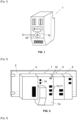
- Fig. 1 represents a device 1 comprising a security system according to the invention.
- the security system is more particularly a computer protection device, also called a cybersecurity system.
- the device 1 is implemented in a programmable logic controller (PLC).
- PLC programmable logic controller
- Such a controller is configured to control a domestic or industrial process, in particular by sequential processing of information. More particularly, the controller makes it possible to transmit a command to one or more other controllers or actuators from input data, such as sensor measurements, setpoints or others.
- the PLC allows the control of machines and sensors in a factory or building, or the piloting of an energy management system.
- the device 1 according to the invention relates to a secure automaton.
- the device 1 is a module, such as a communication module, of the PLC. More generally, the device 1 can be any module or industrial equipment allowing remote security configuration.
- the device 1 may be configured to be mounted on a support, for example a rail 2.
- the support 2 generally comprises other devices 3, 4, 5 arranged in a modular manner relative to each other.
- the device 1 can thus be stored in an electrical cabinet (not shown).
- Device 1 generally has a parallelepiped shape. However, other shapes are also possible.
- the device 1 thus comprises a front face 1a, visible on the [ Fig. 2 ], accessible to an operator.
- the device 1 also includes a rear face 1b, visible on the [ Fig. 1 ], likely to come into contact with, in particular, the support 2. Once the device 1 is fixed to the support 2, the rear face 1b is no longer directly accessible to the operator. It is necessary to remove the device 1 from the support 2 in order to be able to access the rear face 1b.
- the device 1 comprises input 10 / output 11 interfaces configured to receive and send information from / to the device 1 for process management.
- the device 1 also comprises a processor 12 (in English “Central Processing Unit”, CPU) configured to process instructions which constitute the computer program for operating the device 1.
- processor 12 in English “Central Processing Unit”, CPU
- the device 1 also comprises a memory 13 configured to store the instructions constituting the operating computer program as well as various information.
- the device 1 also comprises a communication interface 14, wired or wireless, in particular towards a remote server configured to store the data of the device 1.
- the device 1 may comprise a power source, such as a battery (not shown), or be connected directly to an electricity network.
- the device 1 further comprises at least one security system.
- the security system comprises a control element 20 mounted on the device 1.
- control element 20 is advantageously mounted on the rear face 1b of the device 1.
- the control element 20 can be actuated by an operator.
- control element 20 can be manually actuated by the operator.
- control element 20 may comprise a slot allowing the use of a flat screwdriver type element to pivot a selector 21.
- a flat screwdriver type element to pivot a selector 21.
- other types of manual actuation are possible, by means of a key, a crank or any other tool known per se, specific or not.
- other types of control element 20 are possible, such as a pivoting button or others.
- control element 20 can be actuated without contact by the operator.
- the actuation is advantageously carried out at short range.
- short range is meant in particular an actuation by wireless communication with the device 1 carried out for example at a distance of less than 1 meter, or even advantageously at a distance of less than 10 centimeters.
- Such short-range communication can for example use near field communication (NFC) technology.
- NFC near field communication
- Such short-range communication is advantageously secure in terms of authentication, integrity, and confidentiality of information.
- control element 20 is operable between at least a first position and a second position.
- the device 1 In the first position (illustrated by position A on the [ Fig. 4 ]), the device 1 is in a high security state. More particularly, the device 1 requires a prior security configuration in order to be used. Such a configuration makes it possible to implement protection functions, in particular software functions, known per se such as data encryption, a firewall, access control, protection diagnostics, updates, or others.
- Device 1 cannot initiate communication until the security state configuration is completed. Once in the security state, communications are authenticated and secured.
- Device 1 In the second position (illustrated by position B on the [ Fig. 4 ]), Device 1 is in a low security state.
- the low security security state may correspond to a standard state, in which the device 1 does not require a security configuration, or includes relatively less important protection functions than those provided in the high security state.
- control element 20 can furthermore be actuated in one or more other positions corresponding to other safety states of the device 1, not described below.
- control element 20 can also be actuated in a third position.
- the device 1 In the third position (illustrated by position C on the [ Fig. 4 ]), the device 1 is in a reset state. More particularly, the device 1 is returned to its initial state, in particular to its factory-set state. The safety configuration as well as some or all of the protection functions possibly implemented by the device 1 are deleted, in particular erased from the memory 13 of the device 1.
- the device 1 advantageously comprises a dedicated output allowing the operator to know the safety status of the device 1, for example via a signaling tower or light column mounted on the electrical cabinet comprising the device 1 or via a software application intended for the operator.
- the device 1 may also include an indicator allowing an operator to know in particular the security status of the device 1.
- the indicator is arranged on the front face 1a of the device 1 as illustrated in the [ Fig. 1 ].
- the indicator comprises one or more indicator lights 15 making it possible to display the security, diagnostic and/or operating status of the device 1.
- the display of the indicator light(s) 15 can in particular be compared by the operator with the position of the security system in order to ensure the integrity of the device 1.
- control element 20 is in one of the first, second or third positions A, B, C, respectively corresponding to the device 1 in the high security state, the low security state or the reset state.
- one step of the method consists in checking whether a security has already been configured on the device 1.
- device 1 can be used.
- the method comprises one or more additional configuration steps.
- CS_conf security data can be downloaded by the device 1, in particular by means of the communication interface 14. The download is done for example via Ethernet or USB communication from a specific configuration application stored in a remote server or in an internal web server.
- the CS_conf security data may already be stored in the memory 13 of the device 1.
- the security is configured by means of a computer program advantageously already present in the device 1. Once the configuration has been carried out, the security is implemented and the device 1 can be used.
- the device 1 can be used without requiring any particular security configuration of the device 1.
- control element 20 If the control element 20 is initially the third position, the control element 20 must be actuated to one of the other positions before any use so that the device 1 is in the high or low safety state. The method steps described above can then be implemented subsequently.
- the device 1 When in use, the device 1 is fixed to the support 2. The rear face 1b of the device 1 is then no longer directly accessible to the operator.
- control element 20 is advantageously deactivated when the device 1 is used, in particular connected to the power source.
- the safety system may include an alarm (not shown), for example visual or audible, to warn the operator.
- control element 20 to switch from a high security state to a low security state, or vice versa, it is first necessary to actuate the control element 20 in the third position.
- the security configuration is necessarily deleted before device 1 can transition to the other security state. This ensures that no information about the configuration of device 1 can be retained in the weak security state, which is potentially more vulnerable to cyberattacks.
Landscapes
- Engineering & Computer Science (AREA)
- Physics & Mathematics (AREA)
- Theoretical Computer Science (AREA)
- General Physics & Mathematics (AREA)
- Computer Hardware Design (AREA)
- Computer Security & Cryptography (AREA)
- Software Systems (AREA)
- General Engineering & Computer Science (AREA)
- Mathematical Physics (AREA)
- Computer Networks & Wireless Communication (AREA)
- Microelectronics & Electronic Packaging (AREA)
- Automation & Control Theory (AREA)
- Programmable Controllers (AREA)
- Alarm Systems (AREA)
- User Interface Of Digital Computer (AREA)
- Selective Calling Equipment (AREA)
Description
- La présente invention concerne un système de sécurité ou de sécurisation.
- Elle relève du domaine des applications d'automatisme, notamment pour des automatismes industriels, du bâtiment ou des systèmes de contrôle et/ou de commande d'un réseau de distribution d'énergie.
- Il est connu d'utiliser des automates programmables pour la gestion de processus domestiques ou industriels, par exemple pour la gestion d'un réseau d'électricité.
- Afin d'assurer la sécurité de ces processus contre tout risque de vol de données ou tentative d'intrusion malveillante, les automates comprennent généralement un ou plusieurs systèmes de sécurité permettant d'assurer le contrôle et l'intégrité des données stockées ainsi que la fiabilité des communications des automates.
- Ces systèmes de sécurité peuvent par exemple prendre la forme de logiciels (outil anti-malware, pare-feu, recherche de vulnérabilité, etc.) ou de restrictions d'accès physiques ( clés, de mots de passes chiffrés, etc.).
- A titre d'exemple, afin de contrôler l'accès local direct à certains modules d'automates, ceux-ci comprennent un système de sécurisation sous la forme d'une interface homme machine, nécessitant qu'un opérateur rentre un mot de passe sur un clavier s'il souhaite accéder à l'automate.
- Toutefois, de tels systèmes n'apportent pas entièrement satisfaction.
- En effet, il est nécessaire de prévoir une interface homme machine par module de l'automate. Outre le fait qu'une interface homme machine est onéreuse, longue à mettre en œuvre sur chaque module et est fortement consommatrice d'énergie, celle-ci peut être vulnérable si le mot de passe a été divulgué ou volé.
- En outre, bien que certaines situations de fonctionnement nécessitent un état de sécurité élevé des automates, un état de sécurité plus faible peut également être suffisants dans d'autres situations de fonctionnement, ne nécessitant donc pas de systèmes de sécurité relativement complexes.
- Le document de l'état de la technique
WO2018038536 divulgue un procédé qui consiste à accorder à l'utilisateur qui utilise un terminal en mode de verrouillage et en mode de déverrouillage une première et une seconde autorité qui permettent à l'utilisateur de piloter respectivement le premier et le second ensemble d'éléments. Le second ensemble comprend plus d'éléments que le premier ensemble. Le premier résultat est obtenu en pilotant l'élément du premier ensemble en mode de verrouillage. Le mode de verrouillage est commuté en mode de déverrouillage tout en effaçant une partie des premiers résultats après l'obtention du premier résultat, empêchant les premiers résultats d'affecter les éléments du second ensemble lorsque l'utilisateur utilise le terminal en mode de déverrouillage. - L'invention vient améliorer la situation.
- L'invention vise plus particulièrement à fournir un système de sécurisation efficace pour un dispositif, tel qu'un automate, pour un usage particulièrement simple et flexible, permettant notamment de faire varier l'état de sécurité de façon simple et sécurisée en fonction des besoins de fonctionnement.
- Il est proposé un système de sécurisation monté sur un dispositif, le système de sécurisation comprenant un élément de commande actionnable par un opérateur au moins :
- dans première position, dans laquelle le dispositif est configuré pour être dans un état de sécurité élevé, et
- dans deuxième position, dans laquelle le dispositif est configuré pour être dans un état de sécurité faible.
- Grâce à ces dispositions, l'actionnement d'un élément de commande au niveau du dispositif permet de déterminer l'état de sécurité attendu. Il est ainsi mis en œuvre des moyens à la fois de contrôle d'accès physiques et des moyens logiciels particulièrement simples et efficaces pour assurer la sécurité du dispositif.
- Plus particulièrement, une connexion à distance au dispositif ne permet pas de modifier son état de sécurité, un accès direct et l'actionnement du système de sécurisation étant nécessaire.
- Selon un autre aspect, il est proposé un dispositif comprenant un tel système de sécurisation.
- Selon un autre aspect, il est proposé un procédé de fonctionnement d'un tel système de sécurisation, comprenant les étapes suivantes :
- si l'élément de commande est dans la première position :
- vérifier si une sécurité a déjà été configurée sur le dispositif, et
- si non, télécharger des données de configuration spécifiques au dispositif et configurer la sécurité sur le dispositif avant son utilisation.
- Selon un autre aspect, il est proposé un programme informatique comportant des instructions pour la mise en œuvre de tout ou partie d'un procédé tel que défini dans les présentes lorsque ce programme est exécuté par un processeur.
- Selon un autre aspect, il est proposé un support d'enregistrement non transitoire, lisible par un ordinateur, sur lequel est enregistré un tel programme.
- Par « ordinateur », on entend tout support de traitement d'information programmable, par exemple un processeur compris dans un ordinateur fixe, tablette, téléphone portable ou autres.
- Les caractéristiques exposées dans les paragraphes suivants peuvent, optionnellement, être mises en œuvre. Elles peuvent être mises en œuvre indépendamment les unes des autres ou en combinaison les unes avec les autres :
- L'état de sécurité élevée comprend une configuration de fonctions de protection logicielles.
- L'élément de commande est actionnable par un opérateur manuellement.
- L'élément de commande comprend une fente permettant de faire pivoter un sélecteur entre au moins la première position et la deuxième position.
- L'élément de commande est actionnable par un opérateur au moyen d'une communication sans fil avec le dispositif effectuée à courte portée.
- L'élément de commande est également actionnable dans une troisième position, dans laquelle le dispositif est dans un état réinitialisé.
- Le dispositif est un automate programmable industriel ou un module d'automate programmable industriel.
- Le dispositif comprend une face avant et une face arrière, le système de sécurisation étant monté sur la face arrière, la face arrière étant configurée pour être disposé en contact avec un support.
- Le procédé comprend les étapes suivantes :
- si l'élément de commande est dans la troisième position :
- actionner l'élément de commande dans la première position ou la deuxième position.
- L'actionnement de l'élément de commande entre la première position et la deuxième position nécessite un passage intermédiaire dans la troisième position.
- D'autres caractéristiques, détails et avantages apparaîtront à la lecture de la description détaillée ci-après, et à l'analyse des dessins annexés, sur lesquels :
-
Fig. 1
[Fig. 1 ] montre une vue en perspective de la face arrière d'un dispositif comprenant un système de sécurisation selon un mode de réalisation. -
Fig. 2
[Fig. 2 ] montre une vue en perspective de la face avant du dispositif de la [Fig. 1 ] fixé sur un support avec d'autres dispositifs. -
Fig. 3
[Fig. 3 ] montre un vue schématique du dispositif de la [Fig. 1 ]. -
Fig. 4
[Fig. 4 ] montre une vue agrandie partielle de la face arrière du dispositif de la [Fig. 1 ]. -
Fig. 5
[Fig. 5 ] montre un schéma illustrant le procédé de fonctionnement du système de sécurisation selon un mode de réalisation. - Les dessins et la description ci-après contiennent, pour l'essentiel, des éléments de caractère certain. Ils pourront donc non seulement servir à mieux faire comprendre la présente divulgation, mais aussi contribuer à sa définition, le cas échéant.
- Il est fait référence à la [
Fig. 1 ], qui représente un dispositif 1 comprenant un système de sécurisation selon l'invention. Le système de sécurisation est plus particulièrement un dispositif de protection informatique, également appelé système de cybersécurité. - Selon une réalisation, le dispositif 1 est mis en œuvre dans un automate programmable industriel (API ; en anglais « Programmable Logic Controller », PLC). Un tel automate est configuré pour commander un processus domestique ou industriel, notamment par un traitement séquentiel d'informations. Plus particulièrement, l'automate permet de transmettre une commande à un ou plusieurs aux autres automates ou actionneurs à partir de données d'entrées, tels que des mesures de capteurs, de consigne ou autres.
- A titre d'exemple, l'automate permet la commande de machines et de capteurs dans une usine ou un bâtiment, ou le pilotage d'un système de gestion d'énergie.
- Avantageusement, le dispositif 1 selon l'invention concerne un automate sécurisé.
- Selon une réalisation, le dispositif 1 est un module, tel qu'un module de communication, de l'automate. Plus généralement, le dispositif 1 peut être tout module ou équipement industriel permettant une configuration de sécurité à distance.
- Comme illustré sur la [
Fig. 2 ], le dispositif 1 peut être configuré pour être monté sur un support, par exemple un rail 2. Le support 2 comprend généralement d'autres dispositifs 3, 4, 5 agencés de façon modulaire les uns par rapport aux autres. Le dispositif 1 peut ainsi être stocké dans une armoire électrique (non illustrée). - Le dispositif 1 a généralement une forme parallèpipédique. Toutefois, d'autres formes sont également envisageables.
- Le dispositif 1 comprend ainsi une face avant 1a, visible sur la [
Fig. 2 ], accessible à un opérateur. - Le dispositif 1 comprend également une face arrière 1b, visible sur la [
Fig. 1 ], susceptible de venir en regard, notamment en contact, avec le support 2. Une fois le dispositif 1 fixé sur le support 2, la face arrière 1b n'est plus directement accessible à l'opérateur. Il est nécessaire de démonter le dispositif 1 du support 2 afin de pouvoir accéder à la face arrière 1b. - Comme illustré sur la [
Fig. 2 ] et la [Fig. 3 ], le dispositif 1 comprend des interfaces entrées 10 / sorties 11 configurées pour recevoir et envoyer des informations depuis / vers le dispositif 1 pour la gestion du processus. - Le dispositif 1 comprend également un processeur 12 (en anglais « Central Processing Unit », CPU) configuré pour traiter des instructions qui constituent le programme informatique de fonctionnement du dispositif 1.
- Le dispositif 1 comprend également une mémoire 13 configurée pour stocker les instructions constituant le programme informatique de fonctionnement ainsi que diverses informations.
- Le dispositif 1 comprend également une interface de communication 14, filaire ou sans fil, notamment vers un serveur distant configuré pour stocker les données du dispositif 1.
- Enfin, le dispositif 1 peut comprendre une source d'alimentation, telle qu'une batterie (non illustrée), ou être relié directement à un réseau d'électricité.
- Selon l'invention, le dispositif 1 comprend en outre au moins un système de sécurisation. Le système de sécurisation comprend un élément de commande 20 monté sur le dispositif 1.
- Comme illustré sur la [
Fig. 1 ], l'élément de commande 20 est avantageusement monté sur la face arrière 1b du dispositif 1. - L'élément de commande 20 peut être actionné par un opérateur.
- Selon une réalisation, l'élément de commande 20 peut être actionné manuellement par l'opérateur.
- A cet effet, l'élément de commande 20 peut comprendre une fente permettant l'utilisation d'un élément type tournevis plat pour faire pivoter un sélecteur 21. Toutefois, d'autres types d'actionnements manuels sont possibles, au moyen d'une clé, d'une manivelle ou de tout autre outil connu en soi, spécifique ou non. En outre, d'autres types d'élément de commande 20 sont possibles, tel qu'un bouton pivotant ou autres.
- Selon une autre réalisation, l'élément de commande 20 peut être actionné sans contact par l'opérateur. L'actionnement est avantageusement réalisé à courte portée.
- Par « à courte portée », on entend notamment un actionnement par une communication sans fil avec le dispositif 1 effectuée par exemple à une distance inférieure à 1 mètre, voire avantageusement à distance inférieure à 10 centimètres. Une telle communication à courte portée peut par exemple utiliser la technologie de communication en champ proche (en anglais « Near Field Communication » ; NFC).
- Une telle communication à courte portée est avantageusement sécurisée en termes d'authentification, d'intégrité, et de confidentialité d'information.
- Ainsi, l'élément de commande 20 est actionnable entre au moins une première position et une deuxième position.
- Dans la première position (illustrée par la position A sur la [
Fig. 4 ]), le dispositif 1 est dans un état de sécurité élevé. Plus particulièrement, le dispositif 1 requiert une configuration de sécurité préalable pour pouvoir être utilisé. Une telle configuration permet de mettre en œuvre des fonctions de protection, notamment logicielles, connues en soi telles qu'un cryptage de données, un pare-feu, un contrôle d'accès, un diagnostic de protection, des mises à jour, ou autres. - A titre d'exemple, le dispositif 1 ne peut pas établir de communication tant que la configuration de l'état de sécurité n'a pas été effectuée. Une fois dans l'état de sécurité, les communications sont authentifiées et sécurisées.
- Dans la deuxième position (illustrée par la position B sur la [
Fig. 4 ]), le dispositif 1 est dans un état de sécurité faible. - Par « états de sécurité élevé / faible », on entend que les états de sécurité s'entendent relativement l'un à l'autre. Ainsi, l'état de sécurité de sécurité faible peut correspondre à un état standard, dans lequel le dispositif 1 ne requiert pas de configuration de sécurité, ou comprend des fonctions de protection relativement moins importantes que celles prévues dans l'état de sécurité élevé.
- Selon une réalisation, l'élément de commande 20 peut en outre être actionné dans une ou plusieurs autres positions correspondant à d'autres états de sécurité du dispositif 1, non décrits par la suite.
- Selon le mode de réalisation illustré sur la [
Fig. 4 ], l'élément de commande 20 peut également être actionné dans une troisième position. - Dans la troisième position (illustrée par la position C sur la [
Fig. 4 ]), le dispositif 1 est dans un état réinitialisé. Plus particulièrement, le dispositif 1 est remis dans son état initial, notamment dans son état de sortie d'usine. La configuration de sécurité ainsi qu'une partie ou toutes les fonctions de protection éventuellement mises en œuvre par le dispositif 1 sont supprimées, notamment effacées de la mémoire 13 du dispositif 1. - Le dispositif 1 comprend avantageusement une sortie dédiée permettant à l'opérateur de connaitre l'état de sécurité du dispositif 1, par exemple via une tour de signalisation ou colonne lumineuse montée sur l'armoire électrique comprenant le dispositif 1 ou via une application logicielle à destination de l'opérateur.
- Le dispositif 1 peut également comprendre un indicateur permettant à un opérateur de connaître notamment l'état de sécurité du dispositif 1. L'indicateur est disposé sur la face avant 1a du dispositif 1 comme illustré sur la [
Fig. 1 ]. - Selon une réalisation, l'indicateur comprend un ou plusieurs voyants lumineux 15 permettant d'afficher l'état de sécurité, de diagnostic et/ou de fonctionnement du dispositif 1. L'affichage du ou des voyants 15 peut notamment être comparé par l'opérateur avec la position du système de sécurisation afin de s'assurer de l'intégrité du dispositif 1.
- On décrit ci-après un procédé de fonctionnement, et plus particulièrement d'installation, du système de sécurisation du dispositif 1, en lien avec la [
Fig. 5 ]. - Initialement, l'élément de commande 20 se trouve dans l'une des première, deuxième ou troisième positions A, B, C, correspondant respectivement au dispositif 1 dans l'état de sécurité élevé, l'état de sécurité faible ou l'état réinitialisé.
- Si l'élément de commande 20 est initialement dans la première position, une étape du procédé consiste à vérifier si une sécurité a déjà été configurée sur le dispositif 1.
- En cas de configuration déjà réalisée, le dispositif 1 peut être utilisé.
- En cas de sécurité non encore configurée sur le dispositif 1, le procédé comprend une ou plusieurs étapes de configuration supplémentaires. Lors de ces étapes de configuration, des données de sécurité CS_conf peuvent être téléchargées par le dispositif 1, notamment au moyen de l'interface de communication 14. Le téléchargement se fait par exemple via une communication Ethernet ou USB depuis une application de configuration spécifique stockée dans un serveur distant ou dans un serveur web interne.
- En variante, les données de sécurité CS_conf peuvent déjà être stockées dans la mémoire 13 du dispositif 1.
- La sécurité est configurée au moyen d'un programme informatique avantageusement déjà présent dans le dispositif 1. Une fois la configuration effectuée, la sécurité est mise en œuvre et le dispositif 1 peut être utilisé.
- Si l'élément de commande 20 est initialement dans la deuxième position, le dispositif 1 peut être utilisé sans nécessiter de configuration de sécurité particulière du dispositif 1.
- Si l'élément de commande 20 est initialement la troisième position, l'élément de commande 20 doit être actionné dans l'une des autres positions avant toute utilisation afin que le dispositif 1 soit dans l'état de sécurité élevé ou faible. Les étapes du procédé décrites ci-dessus peuvent alors être mises en œuvre par la suite.
- Lors de son utilisation, le dispositif 1 est fixé au support 2. La face arrière 1b du dispositif 1 n'est alors plus directement accessible à l'opérateur.
- En outre, l'actionnement de l'élément de commande 20 est avantageusement désactivé lorsque le dispositif 1 est utilisé, notamment relié à la source d'alimentation.
- Cela permet d'éviter que l'élément de commande 20 puisse être facilement actionné pour modifier l'état de sécurité du dispositif 1 après sa mise en marche.
- Ainsi, si l'on souhaite passer de l'état de sécurité élevé à l'état de sécurité faible, ou inversement, il est nécessaire au préalable de débrancher le dispositif 1 de la source d'alimentation et/ou de séparer le dispositif 1 du support 2 afin que la face arrière 1b du dispositif 1 soit de nouveau accessible.
- En cas d'actionnement non permis de l'élément de commande 20, le système de sécurisation peut comprendre une alarme (non illustrée), par exemple visuelle ou sonore, permettant d'avertir l'opérateur.
- Selon une réalisation, pour passer d'un état de sécurité élevé à un état de sécurité faible, ou inversement, il est préalablement nécessaire d'actionner l'élément de commande 20 dans la troisième position.
- Ainsi, la configuration de sécurité est nécessairement supprimée avant que le dispositif 1 ne puisse passer dans l'autre état de sécurité. Cela permet de s'assurer qu'aucune information relative à la configuration du dispositif 1 ne puisse être conservée dans l'état de sécurité faible, potentiellement plus vulnérable à des cyberattaques.
- Bien évidemment, l'invention n'est pas limitée aux modes de réalisation décrits précédemment et fournis uniquement à titre d'exemple. Elle englobe diverses modifications, formes alternatives et autres variantes que pourra envisager l'homme du métier dans le cadre de la présente invention et notamment toutes combinaisons des différents modes de fonctionnement décrits précédemment, pouvant être pris séparément ou en association.
Claims (12)
- Système de sécurisation monté sur un dispositif (1) faisant partie d'un automate programmable industriel et comprenant une face avant (1a) et une face arrière (1b), le système de sécurisation étant monté sur la face arrière (1b), la face arrière (1b) étant configurée pour être disposé en contact avec un support (2) lors de l'utilisation du dispositif, le système de sécurisation comprenant un élément de commande (20) actionnable par un opérateur au moins :- dans première position, dans laquelle le dispositif (1) est configuré pour être dans un état de sécurité élevé, et- dans deuxième position, dans laquelle le dispositif (1) est configuré pour être dans un état de sécurité faible,dans lequel la face arrière (1b) du dispositif (1) n'est pas directement accessible à l'opérateur lorsque la face arrière (1b) est en contact avec le support (2).
- Système de sécurisation selon la revendication 1, dans lequel l'état de sécurité élevée comprend une configuration de fonctions de protection logicielles du dispositif (1).
- Système de sécurisation selon la revendication 1 ou 2, dans lequel l'élément de commande (20) est actionnable par un opérateur manuellement.
- Système de sécurisation selon la revendication 3, dans lequel l'élément de commande (20) comprend une fente permettant de faire pivoter un sélecteur (21) entre au moins la première position et la deuxième position.
- Système de sécurisation selon la revendication 1 ou 2, dans lequel l'élément de commande (20) est actionnable par un opérateur au moyen d'une communication sans fil avec le dispositif (1) effectuée à courte portée.
- Système de sécurisation selon l'une quelconque des revendications précédentes, dans lequel l'élément de commande (20) est également actionnable dans une troisième position, dans laquelle le dispositif (1) est dans un état réinitialisé.
- Dispositif (1) comprenant le système de sécurisation selon l'une quelconque des revendications précédentes.
- Procédé de fonctionnement du système de sécurisation selon l'une quelconque des revendications 1 à 6, comprenant les étapes suivantes :- si l'élément de commande (20) est dans la première position :- vérifier si une sécurité a déjà été configurée sur le dispositif (1), et- si non, télécharger des données de configuration spécifiques au dispositif (1) et configurer l'état de sécurité élevé du dispositif (1) avant son utilisation.
- Procédé selon la revendication 8 de fonctionnement du système de sécurisation selon la revendication 6, comprenant les étapes suivantes :- si l'élément de commande (20) est dans la troisième position :- actionner l'élément de commande (20) dans la première position ou la deuxième position.
- Procédé selon la revendication 9, dans lequel l'actionnement de l'élément de commande (20) entre la première position et la deuxième position nécessite un passage intermédiaire dans la troisième position.
- Programme informatique comportant des instructions pour la mise en œuvre du procédé selon l'une des revendications 8 à 10 lorsque ce programme est exécuté par un ordinateur.
- Support d'enregistrement non transitoire lisible par un ordinateur sur lequel est enregistré un programme pour la mise en œuvre du procédé selon l'une des revendications 8 à 10 lorsque ce programme est exécuté par un ordinateur.
Applications Claiming Priority (1)
| Application Number | Priority Date | Filing Date | Title |
|---|---|---|---|
| FR1909965A FR3100635B1 (fr) | 2019-09-10 | 2019-09-10 | Système de sécurisation d’un dispositif |
Publications (2)
| Publication Number | Publication Date |
|---|---|
| EP3792807A1 EP3792807A1 (fr) | 2021-03-17 |
| EP3792807B1 true EP3792807B1 (fr) | 2025-03-05 |
Family
ID=69468663
Family Applications (1)
| Application Number | Title | Priority Date | Filing Date |
|---|---|---|---|
| EP20190930.6A Active EP3792807B1 (fr) | 2019-09-10 | 2020-08-13 | Système de sécurisation d'un dispositif |
Country Status (5)
| Country | Link |
|---|---|
| US (1) | US11182991B2 (fr) |
| EP (1) | EP3792807B1 (fr) |
| CN (1) | CN112559986B (fr) |
| ES (1) | ES3026182T3 (fr) |
| FR (1) | FR3100635B1 (fr) |
Citations (1)
| Publication number | Priority date | Publication date | Assignee | Title |
|---|---|---|---|---|
| CN206002929U (zh) * | 2016-08-12 | 2017-03-08 | 贝加莱工业自动化(中国)有限公司 | 新型plc分布式io模块以及plc分布式io模块组 |
Family Cites Families (40)
| Publication number | Priority date | Publication date | Assignee | Title |
|---|---|---|---|---|
| US4484306A (en) * | 1982-03-22 | 1984-11-20 | Exide Electronics Corporation | Method and apparatus for controlling access in a data transmission system |
| US5212359A (en) * | 1992-02-03 | 1993-05-18 | Eastman Kodak Company | Multiple interface safety switch actuating mechanism |
| US6172875B1 (en) * | 1998-11-17 | 2001-01-09 | Rockwell Technologies, Llc | Programmable logic controller module assembly and locking system |
| EP1329787B1 (fr) * | 2002-01-16 | 2019-08-28 | Texas Instruments Incorporated | Indicateur de mode protégé pour téléphones intelligents et pour assistants numériques personnels (PDA) |
| US8112601B2 (en) * | 2004-08-09 | 2012-02-07 | Jasim Saleh Al-Azzawi | Data storage device with security feature |
| US20120099219A1 (en) * | 2004-08-09 | 2012-04-26 | Jasim Saleh Al-Azzawi | Secure data storage device |
| JP4363361B2 (ja) * | 2005-04-28 | 2009-11-11 | 沖電気工業株式会社 | 携帯用電子機器,セキュリティシステムおよび携帯用電子機器の動作許可範囲決定方法 |
| US20070098175A1 (en) * | 2005-10-31 | 2007-05-03 | Systech Corporation | Security enabler device and method for securing data communications |
| EP1865435A1 (fr) * | 2006-06-06 | 2007-12-12 | Texas Instruments France | Amélioration du contrôle d'exception |
| US8149587B2 (en) * | 2007-11-13 | 2012-04-03 | Rockwell Automation Technologies, Inc. | Drive modularity |
| US8549780B2 (en) * | 2008-03-12 | 2013-10-08 | Armatix Gmbh | Safety device for firearms and method for securing firearms provided with a safety device |
| US20100071054A1 (en) * | 2008-04-30 | 2010-03-18 | Viasat, Inc. | Network security appliance |
| CN102124473B (zh) * | 2008-06-09 | 2014-06-11 | 蔡如邕 | 具有多重选择性确定的可切换安全模式的安全电磁数据存储元件 |
| US8279048B2 (en) * | 2008-09-29 | 2012-10-02 | Amtech Systems, LLC | RFID tag with piezoelectric sensor for power and input data |
| EP2352321B1 (fr) * | 2008-10-31 | 2019-09-11 | ZTE Corporation | Procédé et dispositif de traitement d authentification de terminaux mobiles |
| US8756391B2 (en) * | 2009-05-22 | 2014-06-17 | Raytheon Company | Multi-level security computing system |
| US8253554B2 (en) * | 2009-08-11 | 2012-08-28 | Empire Technology Development Llc | Multi-purpose attachable alarm |
| US8464038B2 (en) * | 2009-10-13 | 2013-06-11 | Google Inc. | Computing device with developer mode |
| US20110199225A1 (en) * | 2010-02-15 | 2011-08-18 | Honeywell International Inc. | Use of token switch to indicate unauthorized manipulation of a protected device |
| SG177781A1 (en) * | 2010-07-08 | 2012-02-28 | Rockwell Automation Tech Inc | Interlocking system for connecting a programmable logic controller and a power supply |
| US8813244B1 (en) * | 2011-02-28 | 2014-08-19 | Google Inc. | Developer switch |
| US9098692B2 (en) * | 2012-03-15 | 2015-08-04 | Yu Yung Choi | Secure electromagnetic data storage element having a selectively determind switchable security mode |
| GB201218389D0 (en) * | 2012-10-12 | 2012-11-28 | Uni I Olso | Multi-mode computer with selector |
| KR102013940B1 (ko) * | 2012-12-24 | 2019-10-21 | 삼성전자주식회사 | 어플리케이션의 보안성 관리 방법 및 그 전자 장치 |
| US9552472B2 (en) * | 2013-05-29 | 2017-01-24 | Blackberry Limited | Associating distinct security modes with distinct wireless authenticators |
| KR20150094178A (ko) * | 2014-02-10 | 2015-08-19 | 삼성전자주식회사 | 보안 장치 및 보안 장치의 제어 방법 |
| WO2015128341A1 (fr) * | 2014-02-26 | 2015-09-03 | Bernecker + Rainer Industrie-Elektronik Ges.M.B.H | Procédé pour faire fonctionner un élément de commutation sûr d'une installation |
| US9219358B2 (en) * | 2014-03-26 | 2015-12-22 | Elbex Video Ltd. | Intelligent support box for electric hybrid switches, power outlets and combinations thereof |
| KR101678619B1 (ko) * | 2015-04-27 | 2016-11-22 | 한국과학기술원 | 하드웨어 기반의 보안 장치 및 이를 이용한 보안 방법 |
| DE102015213744A1 (de) * | 2015-07-21 | 2017-01-26 | Ellenberger & Poensgen Gmbh | Stromverteiler |
| US10581809B2 (en) * | 2015-10-05 | 2020-03-03 | Volodymyr Vasiliovich Khylenko | Device for sending confidential messages using a mobile telephone (gadget) |
| CN105912899A (zh) * | 2016-03-31 | 2016-08-31 | 联想(北京)有限公司 | 一种控制电子设备的方法以及电子设备 |
| EP3488501A4 (fr) * | 2016-07-21 | 2020-03-25 | Canary Connect, Inc. | Ensemble de connecteur réversible pour l'alimentation et les données |
| US11762493B2 (en) * | 2016-08-25 | 2023-09-19 | Jaelark JUNG | Data processing terminals and related methods in lock, intermediate, and unlock modes |
| US9720700B1 (en) * | 2016-10-05 | 2017-08-01 | Apricorn | Secure storage devices, with physical input device, for secure configuration in a configuration-ready mode |
| US10440827B2 (en) * | 2017-01-12 | 2019-10-08 | Kmc Controls, Inc. | Programmable logic controller override |
| WO2019066883A1 (fr) * | 2017-09-29 | 2019-04-04 | Siemens Aktiengesellschaft | Déploiement de fonctionnalité de sécurité déclarative prête à l'emploi pour plateforme d'ingénierie |
| TWM556771U (zh) * | 2017-10-26 | 2018-03-11 | International Currency Tech Corporation | 具噴墨保鈔功能之安全錢箱 |
| US11686594B2 (en) * | 2018-02-17 | 2023-06-27 | Ei Electronics Llc | Devices, systems and methods for a cloud-based meter management system |
| US10608819B1 (en) * | 2019-09-24 | 2020-03-31 | Apricorn | Portable storage device with internal secure controller that performs self-verification and self-generates encryption key(s) without using host or memory controller and that securely sends encryption key(s) via side channel |
-
2019
- 2019-09-10 FR FR1909965A patent/FR3100635B1/fr active Active
-
2020
- 2020-08-13 EP EP20190930.6A patent/EP3792807B1/fr active Active
- 2020-08-13 ES ES20190930T patent/ES3026182T3/es active Active
- 2020-09-01 CN CN202010902362.5A patent/CN112559986B/zh active Active
- 2020-09-02 US US17/009,844 patent/US11182991B2/en active Active
Patent Citations (1)
| Publication number | Priority date | Publication date | Assignee | Title |
|---|---|---|---|---|
| CN206002929U (zh) * | 2016-08-12 | 2017-03-08 | 贝加莱工业自动化(中国)有限公司 | 新型plc分布式io模块以及plc分布式io模块组 |
Non-Patent Citations (1)
| Title |
|---|
| WILKINSON GARY: "TriStation 1131 Developer's Workbench", 1 October 2004 (2004-10-01), pages 1 - 352, XP093233422, Retrieved from the Internet <URL:https://web.archive.org/web/20170505084508/https://www.nrc.gov/docs/ML0932/ML093290419.pdf> [retrieved on 20170505] * |
Also Published As
| Publication number | Publication date |
|---|---|
| US11182991B2 (en) | 2021-11-23 |
| US20210074098A1 (en) | 2021-03-11 |
| ES3026182T3 (en) | 2025-06-10 |
| FR3100635B1 (fr) | 2021-08-06 |
| CN112559986B (zh) | 2025-11-07 |
| FR3100635A1 (fr) | 2021-03-12 |
| EP3792807A1 (fr) | 2021-03-17 |
| CN112559986A (zh) | 2021-03-26 |
Similar Documents
| Publication | Publication Date | Title |
|---|---|---|
| EP1964307B1 (fr) | Procédé pour la réalisation d'un compteur sécurisé sur un système informatique embarqué disposant d'une carte a puce. | |
| EP1004100B1 (fr) | Dispositif portable electronique pour systeme de communication securisee, et procede d'initialisation de ses parametres | |
| EP2659419B1 (fr) | Procédé et dispositif de contrôle d'accès à un système informatique | |
| WO2016102888A1 (fr) | Procédé de transmission sécurisée d'une clé virtuelle et méthode d'authentification d'un terminal mobile | |
| FR2989799A1 (fr) | Procede de transfert d'un dispositif a un autre de droits d'acces a un service | |
| WO2010125309A1 (fr) | Systeme de programmation et de gestion securisees pour serrures comportant des moyens de communication sans contact et commandables par un telephone portable nfc | |
| EP3544039B1 (fr) | Procédé de consignation d'une fonction d'un appareil électrique et appareil électrique mettant en oeuvre ce procédé | |
| WO2016102889A1 (fr) | Procédé de contrôle de l'accès à au moins une fonctionnalité d'un véhicule automobile | |
| FR2811097A1 (fr) | Dispositif de commande de cryptage | |
| FR3013541A1 (fr) | Procede et dispositif pour la connexion a un service distant | |
| EP2077515A1 (fr) | Dispositif, systèmes et procédé de démarrage sécurisé d'une installation informatique | |
| WO2017207894A1 (fr) | Procédé pour renseigner des informations personnelles d'un utilisateur demandées par un service en ligne donné | |
| EP3792807B1 (fr) | Système de sécurisation d'un dispositif | |
| EP2687003A1 (fr) | Procede de saisie d'un code a l'aide d'un dispositif portatif et dispositif portatif associe | |
| FR2878355A1 (fr) | Unite de tachigraphe electronique pour vehicule automobile | |
| EP3195641B1 (fr) | Procédé d'appairage | |
| EP3528464B1 (fr) | Procédé d'appairage de terminaux électroniques, dispositifs d'appairage, terminaux et programme correspondant | |
| FR2791509A1 (fr) | Dispositif antivol pour telephone mobile | |
| EP2377290A1 (fr) | Procede et dispositif de transfert securise de donnees numeriques | |
| EP2071799B1 (fr) | Procédé et serveur pour l'accès a un coffre-fort électronique via plusieurs entités | |
| EP3317800B1 (fr) | Procédé de gestion de profils dans un élément sécurisé | |
| FR2985052A1 (fr) | Dispositif electronique pour le stockage de donnees confidentielles | |
| EP2045749B1 (fr) | Procédé de sécurisation d'un terminal équipé d'au moins une interface de communication | |
| EP2911365A1 (fr) | Procédé et système de sécurisation de transactions offertes par une pluralité de services entre un appareil mobile d'un utilisateur et un point d'acceptation | |
| EP2537314B1 (fr) | Procédé et dispositif de propagation d'événements de gestion de session |
Legal Events
| Date | Code | Title | Description |
|---|---|---|---|
| PUAI | Public reference made under article 153(3) epc to a published international application that has entered the european phase |
Free format text: ORIGINAL CODE: 0009012 |
|
| STAA | Information on the status of an ep patent application or granted ep patent |
Free format text: STATUS: THE APPLICATION HAS BEEN PUBLISHED |
|
| AK | Designated contracting states |
Kind code of ref document: A1 Designated state(s): AL AT BE BG CH CY CZ DE DK EE ES FI FR GB GR HR HU IE IS IT LI LT LU LV MC MK MT NL NO PL PT RO RS SE SI SK SM TR |
|
| AX | Request for extension of the european patent |
Extension state: BA ME |
|
| STAA | Information on the status of an ep patent application or granted ep patent |
Free format text: STATUS: REQUEST FOR EXAMINATION WAS MADE |
|
| 17P | Request for examination filed |
Effective date: 20210908 |
|
| RBV | Designated contracting states (corrected) |
Designated state(s): AL AT BE BG CH CY CZ DE DK EE ES FI FR GB GR HR HU IE IS IT LI LT LU LV MC MK MT NL NO PL PT RO RS SE SI SK SM TR |
|
| RIC1 | Information provided on ipc code assigned before grant |
Ipc: G05B 9/02 20060101ALI20241115BHEP Ipc: G06F 21/76 20130101ALI20241115BHEP Ipc: G06F 21/74 20130101AFI20241115BHEP |
|
| GRAP | Despatch of communication of intention to grant a patent |
Free format text: ORIGINAL CODE: EPIDOSNIGR1 |
|
| STAA | Information on the status of an ep patent application or granted ep patent |
Free format text: STATUS: GRANT OF PATENT IS INTENDED |
|
| RIC1 | Information provided on ipc code assigned before grant |
Ipc: G05B 19/05 20060101ALI20241218BHEP Ipc: G05B 9/02 20060101ALI20241218BHEP Ipc: G06F 21/76 20130101ALI20241218BHEP Ipc: G06F 21/74 20130101AFI20241218BHEP |
|
| GRAS | Grant fee paid |
Free format text: ORIGINAL CODE: EPIDOSNIGR3 |
|
| INTG | Intention to grant announced |
Effective date: 20250103 |
|
| GRAA | (expected) grant |
Free format text: ORIGINAL CODE: 0009210 |
|
| STAA | Information on the status of an ep patent application or granted ep patent |
Free format text: STATUS: THE PATENT HAS BEEN GRANTED |
|
| AK | Designated contracting states |
Kind code of ref document: B1 Designated state(s): AL AT BE BG CH CY CZ DE DK EE ES FI FR GB GR HR HU IE IS IT LI LT LU LV MC MK MT NL NO PL PT RO RS SE SI SK SM TR |
|
| REG | Reference to a national code |
Ref country code: GB Ref legal event code: FG4D Free format text: NOT ENGLISH |
|
| REG | Reference to a national code |
Ref country code: CH Ref legal event code: EP |
|
| REG | Reference to a national code |
Ref country code: IE Ref legal event code: FG4D Free format text: LANGUAGE OF EP DOCUMENT: FRENCH |
|
| REG | Reference to a national code |
Ref country code: DE Ref legal event code: R096 Ref document number: 602020047104 Country of ref document: DE |
|
| REG | Reference to a national code |
Ref country code: ES Ref legal event code: FG2A Ref document number: 3026182 Country of ref document: ES Kind code of ref document: T3 Effective date: 20250610 |
|
| PG25 | Lapsed in a contracting state [announced via postgrant information from national office to epo] |
Ref country code: RS Free format text: LAPSE BECAUSE OF FAILURE TO SUBMIT A TRANSLATION OF THE DESCRIPTION OR TO PAY THE FEE WITHIN THE PRESCRIBED TIME-LIMIT Effective date: 20250605 |
|
| PG25 | Lapsed in a contracting state [announced via postgrant information from national office to epo] |
Ref country code: FI Free format text: LAPSE BECAUSE OF FAILURE TO SUBMIT A TRANSLATION OF THE DESCRIPTION OR TO PAY THE FEE WITHIN THE PRESCRIBED TIME-LIMIT Effective date: 20250305 |
|
| REG | Reference to a national code |
Ref country code: NL Ref legal event code: MP Effective date: 20250305 |
|
| REG | Reference to a national code |
Ref country code: LT Ref legal event code: MG9D |
|
| PG25 | Lapsed in a contracting state [announced via postgrant information from national office to epo] |
Ref country code: NO Free format text: LAPSE BECAUSE OF FAILURE TO SUBMIT A TRANSLATION OF THE DESCRIPTION OR TO PAY THE FEE WITHIN THE PRESCRIBED TIME-LIMIT Effective date: 20250605 |
|
| PG25 | Lapsed in a contracting state [announced via postgrant information from national office to epo] |
Ref country code: HR Free format text: LAPSE BECAUSE OF FAILURE TO SUBMIT A TRANSLATION OF THE DESCRIPTION OR TO PAY THE FEE WITHIN THE PRESCRIBED TIME-LIMIT Effective date: 20250305 |
|
| PG25 | Lapsed in a contracting state [announced via postgrant information from national office to epo] |
Ref country code: LV Free format text: LAPSE BECAUSE OF FAILURE TO SUBMIT A TRANSLATION OF THE DESCRIPTION OR TO PAY THE FEE WITHIN THE PRESCRIBED TIME-LIMIT Effective date: 20250305 |
|
| PG25 | Lapsed in a contracting state [announced via postgrant information from national office to epo] |
Ref country code: GR Free format text: LAPSE BECAUSE OF FAILURE TO SUBMIT A TRANSLATION OF THE DESCRIPTION OR TO PAY THE FEE WITHIN THE PRESCRIBED TIME-LIMIT Effective date: 20250606 Ref country code: BG Free format text: LAPSE BECAUSE OF FAILURE TO SUBMIT A TRANSLATION OF THE DESCRIPTION OR TO PAY THE FEE WITHIN THE PRESCRIBED TIME-LIMIT Effective date: 20250305 |
|
| REG | Reference to a national code |
Ref country code: AT Ref legal event code: MK05 Ref document number: 1773584 Country of ref document: AT Kind code of ref document: T Effective date: 20250305 |
|
| PG25 | Lapsed in a contracting state [announced via postgrant information from national office to epo] |
Ref country code: NL Free format text: LAPSE BECAUSE OF FAILURE TO SUBMIT A TRANSLATION OF THE DESCRIPTION OR TO PAY THE FEE WITHIN THE PRESCRIBED TIME-LIMIT Effective date: 20250305 |
|
| PG25 | Lapsed in a contracting state [announced via postgrant information from national office to epo] |
Ref country code: SE Free format text: LAPSE BECAUSE OF FAILURE TO SUBMIT A TRANSLATION OF THE DESCRIPTION OR TO PAY THE FEE WITHIN THE PRESCRIBED TIME-LIMIT Effective date: 20250305 |
|
| PG25 | Lapsed in a contracting state [announced via postgrant information from national office to epo] |
Ref country code: SM Free format text: LAPSE BECAUSE OF FAILURE TO SUBMIT A TRANSLATION OF THE DESCRIPTION OR TO PAY THE FEE WITHIN THE PRESCRIBED TIME-LIMIT Effective date: 20250305 |
|
| PG25 | Lapsed in a contracting state [announced via postgrant information from national office to epo] |
Ref country code: PT Free format text: LAPSE BECAUSE OF FAILURE TO SUBMIT A TRANSLATION OF THE DESCRIPTION OR TO PAY THE FEE WITHIN THE PRESCRIBED TIME-LIMIT Effective date: 20250707 |
|
| PGFP | Annual fee paid to national office [announced via postgrant information from national office to epo] |
Ref country code: ES Payment date: 20250916 Year of fee payment: 6 |
|
| PGFP | Annual fee paid to national office [announced via postgrant information from national office to epo] |
Ref country code: DE Payment date: 20250827 Year of fee payment: 6 |
|
| PG25 | Lapsed in a contracting state [announced via postgrant information from national office to epo] |
Ref country code: PL Free format text: LAPSE BECAUSE OF FAILURE TO SUBMIT A TRANSLATION OF THE DESCRIPTION OR TO PAY THE FEE WITHIN THE PRESCRIBED TIME-LIMIT Effective date: 20250305 |
|
| PGFP | Annual fee paid to national office [announced via postgrant information from national office to epo] |
Ref country code: IT Payment date: 20250825 Year of fee payment: 6 |
|
| PG25 | Lapsed in a contracting state [announced via postgrant information from national office to epo] |
Ref country code: AT Free format text: LAPSE BECAUSE OF FAILURE TO SUBMIT A TRANSLATION OF THE DESCRIPTION OR TO PAY THE FEE WITHIN THE PRESCRIBED TIME-LIMIT Effective date: 20250305 |
|
| PGFP | Annual fee paid to national office [announced via postgrant information from national office to epo] |
Ref country code: FR Payment date: 20250825 Year of fee payment: 6 |
|
| PG25 | Lapsed in a contracting state [announced via postgrant information from national office to epo] |
Ref country code: CZ Free format text: LAPSE BECAUSE OF FAILURE TO SUBMIT A TRANSLATION OF THE DESCRIPTION OR TO PAY THE FEE WITHIN THE PRESCRIBED TIME-LIMIT Effective date: 20250305 Ref country code: EE Free format text: LAPSE BECAUSE OF FAILURE TO SUBMIT A TRANSLATION OF THE DESCRIPTION OR TO PAY THE FEE WITHIN THE PRESCRIBED TIME-LIMIT Effective date: 20250305 |
|
| PG25 | Lapsed in a contracting state [announced via postgrant information from national office to epo] |
Ref country code: RO Free format text: LAPSE BECAUSE OF FAILURE TO SUBMIT A TRANSLATION OF THE DESCRIPTION OR TO PAY THE FEE WITHIN THE PRESCRIBED TIME-LIMIT Effective date: 20250305 |
|
| PG25 | Lapsed in a contracting state [announced via postgrant information from national office to epo] |
Ref country code: SK Free format text: LAPSE BECAUSE OF FAILURE TO SUBMIT A TRANSLATION OF THE DESCRIPTION OR TO PAY THE FEE WITHIN THE PRESCRIBED TIME-LIMIT Effective date: 20250305 |
|
| PG25 | Lapsed in a contracting state [announced via postgrant information from national office to epo] |
Ref country code: IS Free format text: LAPSE BECAUSE OF FAILURE TO SUBMIT A TRANSLATION OF THE DESCRIPTION OR TO PAY THE FEE WITHIN THE PRESCRIBED TIME-LIMIT Effective date: 20250705 |
|
| REG | Reference to a national code |
Ref country code: DE Ref legal event code: R097 Ref document number: 602020047104 Country of ref document: DE |
|
| PLBE | No opposition filed within time limit |
Free format text: ORIGINAL CODE: 0009261 |
|
| STAA | Information on the status of an ep patent application or granted ep patent |
Free format text: STATUS: NO OPPOSITION FILED WITHIN TIME LIMIT |
|
| PG25 | Lapsed in a contracting state [announced via postgrant information from national office to epo] |
Ref country code: DK Free format text: LAPSE BECAUSE OF FAILURE TO SUBMIT A TRANSLATION OF THE DESCRIPTION OR TO PAY THE FEE WITHIN THE PRESCRIBED TIME-LIMIT Effective date: 20250305 |
|
| REG | Reference to a national code |
Ref country code: CH Ref legal event code: L10 Free format text: ST27 STATUS EVENT CODE: U-0-0-L10-L00 (AS PROVIDED BY THE NATIONAL OFFICE) Effective date: 20260114 |
|
| 26N | No opposition filed |
Effective date: 20251208 |
|
| REG | Reference to a national code |
Ref country code: CH Ref legal event code: H13 Free format text: ST27 STATUS EVENT CODE: U-0-0-H10-H13 (AS PROVIDED BY THE NATIONAL OFFICE) Effective date: 20260324 |
|
| PG25 | Lapsed in a contracting state [announced via postgrant information from national office to epo] |
Ref country code: MC Free format text: LAPSE BECAUSE OF FAILURE TO SUBMIT A TRANSLATION OF THE DESCRIPTION OR TO PAY THE FEE WITHIN THE PRESCRIBED TIME-LIMIT Effective date: 20250305 |
|
| PG25 | Lapsed in a contracting state [announced via postgrant information from national office to epo] |
Ref country code: LU Free format text: LAPSE BECAUSE OF NON-PAYMENT OF DUE FEES Effective date: 20250813 |
|
| PG25 | Lapsed in a contracting state [announced via postgrant information from national office to epo] |
Ref country code: CH Free format text: LAPSE BECAUSE OF NON-PAYMENT OF DUE FEES Effective date: 20250831 |