EP3793042A1 - Ensemble de contact - Google Patents
Ensemble de contact Download PDFInfo
- Publication number
- EP3793042A1 EP3793042A1 EP19196517.7A EP19196517A EP3793042A1 EP 3793042 A1 EP3793042 A1 EP 3793042A1 EP 19196517 A EP19196517 A EP 19196517A EP 3793042 A1 EP3793042 A1 EP 3793042A1
- Authority
- EP
- European Patent Office
- Prior art keywords
- rings
- terminal
- spring elements
- assembly according
- conducting
- Prior art date
- Legal status (The legal status is an assumption and is not a legal conclusion. Google has not performed a legal analysis and makes no representation as to the accuracy of the status listed.)
- Granted
Links
Images


Classifications
-
- H—ELECTRICITY
- H01—ELECTRIC ELEMENTS
- H01R—ELECTRICALLY-CONDUCTIVE CONNECTIONS; STRUCTURAL ASSOCIATIONS OF A PLURALITY OF MUTUALLY-INSULATED ELECTRICAL CONNECTING ELEMENTS; COUPLING DEVICES; CURRENT COLLECTORS
- H01R39/00—Rotary current collectors, distributors or interrupters
- H01R39/64—Devices for uninterrupted current collection
Definitions
- the present invention relates to a contact assembly and a radar system, and in particular, to a rotating electrical coupling.
- Radar systems include, for example, a base unit and an antenna installation that is rotating relative to the base unit to scan a surveillance area. Since the antenna installation might be rotatable upon large angles or even continuously, there is a need to provide a reliable electrical contact between the antenna installation and the base unit while both components rotate relative to each other.
- the present invention relates to a contact assembly for electrically connecting a first terminal with a second terminal that are rotatable relative to each other about a rotation axis.
- the assembly comprises a plurality of conducting rings, a plurality of isolating rings, a case, and a plurality of spring elements.
- Each ring of the plurality of conducting rings comprises a contact element at its inner circle for contacting the first terminal.
- the rings of the plurality of isolating rings are alternatively stacked with the plurality of conducting rings to form a stack of rings so that the conducting rings are electrically isolated from each other.
- the case includes a (pivot) bearing for the stack of rings, wherein the stack of rings is rotationally fixed relative to the first terminal.
- the spring elements of the plurality of spring elements are electrically connected to the second terminal and configured to provide multiple sliding electrical contacts to outer circles of the conducting rings while rotating the first terminal relative to the second terminal about the rotational axis.
- the springs are finger-shaped and can be formed as leaf springs that are spring-loaded to provide a spring force.
- the sliding contact can be at an end portion of the finger-shaped springs or be made at an inner portion of the corresponding finger to allow rotations in both directions.
- the case comprises a support for the plurality of spring elements, wherein the support is configured to hold the spring elements while each spring exerts a bias force on the outer circle of the respective conducing ring.
- the bearing is configured to enable a relative rotation between the first terminal and the second terminal in one or both directions of more than 180° or more than 360° or to enable a continuous rotation about the rotation axis. It is understood that the possibility of rotations of more than 180° or more than 360° does not imply that it has to rotate about these angles. Instead, the contact assembly may rotate about any angle between 0° to a maximum angle, which may be more than 180° or 360°.
- each of the conducting rings are formed along a helical path at the inner circles of the plurality of conducting rings so that adjacent conducting rings are contacted at their inner circles at different angular positions about the rotational axis.
- the plurality of isolating rings extends radially further outwards than the plurality of conducting rings to provide grooves associated with each of the conducting rings, each groove guiding a corresponding spring element to prevent shorts between adjacent spring elements.
- the spring elements of the plurality of spring elements are spaced, parallel to the rotational axis, from one another by a plurality of spacers arranged between adjacent spring elements to prevent electrical contacts between adjacent spring elements.
- the support of the plurality of spring elements is a bolt attached to the case, each spring element of the plurality of spring elements may comprise a further contact element and all of them may be formed as a staircase about the bolt (e.g. neighboring spring elements are shifted in an angular direction relative to each other).
- Embodiments allows a large number of electrical contacts at the first terminal and at the second terminals, e.g. are more than 5 or more than 10 or more than 20 can be electrically connected to one another.
- a first plurality of wires is arranged between the first terminal and the plurality of contacts elements at the inner circles of the conducting rings.
- a second plurality of wires is arranged between the second terminal and the further contact elements at the spring elements.
- the assembly is configured to connect a rotating equipment to a fixed installation, wherein the case may comprise:
- the second case portion includes a plate part extending at least partially perpendicular to the rotational axis for securing it to the fixed equipment, wherein the stack of rings forms a cylinder about the rotational axis.
- the case can have a tube-like portion along the rotational axis and, along a cross-sectional plane thereto, a holding portion enabling a secure mounting of the contact assembly during rotation.
- some or all rings of the plurality of conducting rings are made of electrically conducting material in one or more angular sections (only).
- Each angular section may include a contact element at its inner circle.
- the angular sections can be isolated from each other so that the rings are electrically conductive only the in angular sections.
- each ring of the plurality of conducting rings are made of electrically conducting material in multiple angular sections.
- the rings may include electrically isolating portions every 90°, 120° or 180° (i.e. there may be four, three or two angular sections that are isolated from each other).
- at least some spring elements of the plurality of spring elements are arranged to contact multiple angular sections of one or more conducting rings simultaneously.
- embodiments may utilize half rings (or three- or four-part rings) allowing for at least twice as many wires in the same length but with a reduction in movement allowance to under 180°.
- the assembly comprises a switching circuitry that is configured to compensate a switching performed by the spring elements when moving from one angular section to a next angular section upon rotation about the rotation axis.
- a signal path (or all signal paths) between lines of the first terminal and second terminal remains intact. For example, during the rotation, a given line of the first terminal remains in an electrical contact with the same line of the second terminal (no switching of lines caused by the rotation).
- Embodiments relate also to a radar system with: a base unit, an antenna installation, and an assembly as defined before to electrically contact the antenna installation with the base unit.
- the base unit may be connected to the second terminal and may define a fixed assembly (e.g. not subject to any centrifugal force during normal operation), whereas the antenna installation may be connected to the first terminal and may define a rotating assembly (e.g. subject to a centrifugal force during normal operation).
- Embodiments overcome the problems of conventional systems by using a series of rings which are alternating between conductive and isolating rings and using spring-loaded contact elements to establish the electric contact between two relative rotating assemblies.
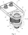
- Fig. 1 depicts a contact assembly according to an embodiment of the present invention.
- This contact assembly is configured for an electrical contact of a first electrical terminal 10 with a second electrical terminal 20 which are rotatable relative to each other about a rotation axis R.
- the assembly comprises a plurality of conducting rings 110, each ring 110 comprising a contact element 111 at its inner circle for contacting the first terminal 10.
- the assembly further comprises a plurality of isolating rings 120 alternatively stacked with the plurality of conducting rings 110 so that the conducting rings 110 are electrically isolated from each other and form together with isolating rings 120 a stack of rings 110, 120 that form a cylinder about the rotational axis R.
- the assembly comprises further a case 130 with pivot bearings 135, 136 for the stack of rings 110, 120, wherein the stack of rings 110, 120 is rotationally fixed relative to the first terminal 10.
- the case 130 may not only provide a housing, but also a support structure or frame for the components like the bearings 135, 136 and the stack of rings 110, 120.
- the contact assembly includes a plurality of springs elements 140 configured to provide multiple sliding electrical contacts between the second terminal 20 and outer circles of rings 110 of the plurality of conducting rings 110 while rotating the first terminal 10 relative to the second terminal 20 about the rotational axis R.
- the spring elements 140 may be held by a bolt 134 (or any other support) and are spring loaded to exert a bias force on an outer surface of the conducting rings 110 to maintain a reliable electric contact during rotation.
- this bolt construction 134 When assembling the assembly this bolt construction 134 may be rotated so that the spring elements 140 are separated from the conducting rings 110 or vice-versa and the stack of rings 110, 120 may be placed between the bearings 135, 136. Finally, the spring elements 140 can be pressed on the conducting rings 110.
- the form of the spring elements 140 can be different from the depicted finger-form that are contacted at their end portions. For example, if rotations in both directions shall be allowed for the contact assembly, the spring elements 140 can contact the conducting rings 110 at inner portions of the finger-shaped spring elements 140.
- Fig. 2 depicts a cross-sectional view along the rotational axis R through the stack of conducting rings 110 and isolating rings 120 that define the cylinder about the rotational axis R.
- This view depicts further details of the first terminal 10 that is formed as a plug connector into which a first cable with multiples lines can be inserted, wherein the connections wires to the conductive rings 110 are not shown in Fig. 2 .
- This first cable may be connected to a rotating assembly whereas a second cable connected to the second terminal 20 may be connected to a stationary assembly.
- the case 130 may comprise a first case portion 131 which is rotationally fixed to first terminal 10.
- the first case portion 131 may provide support for the stack of rings 110, 120 to hold them as rotatable about the axis R.
- the case 130 may include a second case portion 132 that holds the second terminal 20, the spring elements 140, and the bearings 135, 136.
- the second terminal 20 is formed at the second case portion 132 that extends in the direction perpendicular to the rotational axis R to mount the case 130 to the exemplary stationary assembly (not shown).
- Each of the conducting rings 110 comprises the contact element 111 that provides a contact for the lines from the first terminal to an inner circle of the respective conducting ring 110.
- These contact elements 111 are shifted with respect to each other to simplify the wire arrangement inside the stack of rings 110, 120.
- the contact elements 111 may be arranged in a helical shape on an inner surface of the stack of rings 110, 120 (like a spiral stairway).
- the step depth (angular offset) between neighboring contact elements 111 can be adjusted freely. In particular, enough spacing can be provided to prevent electrical shorts.
- the contact elements 111 can arranged such that, when viewed along the axis R, neighboring contact elements 111 do not overlap.
- the spring elements 140 may include further contact elements (not shown) on their sides which remain exposes after stacking the individual spring elements 140.
- These further contact elements can be arranged in a helical or staircase shape (e.g. around a support bolt 134 that holds the spring elements) in order to allow wires to contact separately one of the spring elements 140 without risking any shorts.
- the spring elements 140 are stacked onto each other, wherein each adjacent spring elements 140 may be separated by an isolating element arranged between each two adjacent spring elements 140 to maintain a reliable electrical isolation.
- the bolt support 134 may be formed by an isolated material or is coated therewith to maintain the electrical isolation.
- each of the isolating rings 120 may extend radially further outward than the neighboring conducting rings 110.
- the outer circles of the conducting rings 110 and the isolating rings 120 form a groove structure, in which respective spring elements 140 are guided by side walls formed by outer portions of the isolating rings 120. This has advantage of further preventing short contacts between adjacent spring elements 140.
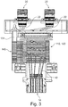
- Fig. 3 depicts another cross-sectional view along the axial direction of the cylindrical stack of rings 110, 120 that illustrate the line routing of the wires to the terminals 10, 20.
- the first terminal 10 includes multiples lines connected with respective first wires 12.
- the second terminal 20 includes multiple lines, each being connected with respective second wires 22 that provide electrical paths to further contact elements on the individual spring elements 140.
- These further contact elements can be formed as stairway around the support 134 of the spring elements 140.
- the (spiral) stairway formed by the contact elements 111 and by the further contact elements on the spring elements 140 provide the advantage that the thereby spaced cable routing of the wires 12, 22 (ideally) circumvent any direct contact of the wires 12, 22. Since the signals through these wires may have a high frequency, this separation improves the (e.g. inductive) decoupling of the respective signal paths.
- Fig. 4 depicts another cross-sectional view along the axial direction of the cylindrical stack of rings 110, 120 in another angular plane when compared to Fig. 3 .
- This view illustrates the support of the stack of rings 110, 120 by the first case portion 131 between a first bearing 135 and a second bearing 136.
- the stack of rings 110, 120 may be held on both sides in the axial direction between a first plate 131a and a second plates 131b, both being attached to each other by a connection element 137 (e.g. a screw connection) that presses the stack of rings 110, 120 onto each other.
- a connection element 137 e.g. a screw connection
- conductive half rings or multiple-part rings are utilized.
- the conducting half rings 110 in Fig. 4 can be electrically isolated along the depicted cross-section and attached to each other, e.g. with an isolating strip in between the two halves.
- the exemplary conductive half rings are formed and supported by the isolating rings and an air gap is formed between the half rings.
- the rotations may be limited to movements under 180°.
- an electronic switching circuitry that connects automatically the lines as desired (e.g. reverses the switching performed by the spring element when moving from one angular section to the next). It is further understood, that it would also be possible to use other multiples - cutting the ring into 3 (with movement reduced to under 120°) or 4 (reduced to under 90°), etc.
- the contact assembly may be a rotating coupling of at least one cable coupled to the top portion (second terminal(s) 20) to another cable at the lower portion (first terminal 10).
- the top portion may be fixed to a stationary external assembly.
- the individual cables or lines from the cable(s) at the second terminal 20 may be separated and passed through the coupling structure to the spring-loaded contact elements at the interface with the rotating coupling.
- the lower half of the rotating coupling may be fixed to a second external assembly which may be referred to as the rotating assembly.
- the lower half of the rotating coupling includes the series of rings 110, 120, alternatively conducting and isolating, and a housing (case 130).
- a cable from the rotating assembly can pass into the lower half via the first terminal of the rotating coupling and may again be separated into individual lines and passed inside the structure to conducting rings 110.
- the sliding contact between the conducting rings 110 and the spring-loaded contacts 140 provide the electrical connection between the fixed assembly and the rotating assembly. The contact is maintained throughout the rotation due to the spring-loaded contact mechanism.
- Embodiments provide the particular advantage that the contact assembly allows to electrically connect a large number of lines with each other. Only the axial length has to be increased in accordance with the number of lines to be contacted with each other. Therefore, the assembly can be scaled to any particular number of lines that shall be connected with each other. For example, with this design it is possible to connect 10 or 20 or even more electrical lines with each other. In addition, the risk of shorts can be effectively avoided by the contact elements 111 being formed as a spiral stairway.
Landscapes
- Details Of Connecting Devices For Male And Female Coupling (AREA)
Priority Applications (2)
| Application Number | Priority Date | Filing Date | Title |
|---|---|---|---|
| EP19196517.7A EP3793042B1 (fr) | 2019-09-10 | 2019-09-10 | Ensemble de contact |
| PCT/EP2020/074591 WO2021047987A1 (fr) | 2019-09-10 | 2020-09-03 | Ensemble contact |
Applications Claiming Priority (1)
| Application Number | Priority Date | Filing Date | Title |
|---|---|---|---|
| EP19196517.7A EP3793042B1 (fr) | 2019-09-10 | 2019-09-10 | Ensemble de contact |
Publications (2)
| Publication Number | Publication Date |
|---|---|
| EP3793042A1 true EP3793042A1 (fr) | 2021-03-17 |
| EP3793042B1 EP3793042B1 (fr) | 2024-08-21 |
Family
ID=67928619
Family Applications (1)
| Application Number | Title | Priority Date | Filing Date |
|---|---|---|---|
| EP19196517.7A Active EP3793042B1 (fr) | 2019-09-10 | 2019-09-10 | Ensemble de contact |
Country Status (2)
| Country | Link |
|---|---|
| EP (1) | EP3793042B1 (fr) |
| WO (1) | WO2021047987A1 (fr) |
Families Citing this family (2)
| Publication number | Priority date | Publication date | Assignee | Title |
|---|---|---|---|---|
| CN117276987B (zh) * | 2023-06-20 | 2024-08-30 | 深圳市东峰盛科技有限公司 | 一种拉线盒导体连接结构和商品防盗安全展示装置 |
| CN117039563A (zh) * | 2023-08-22 | 2023-11-10 | 核星核电科技(海盐)有限公司 | 一种分体式导电滑环 |
Citations (2)
| Publication number | Priority date | Publication date | Assignee | Title |
|---|---|---|---|---|
| CN203009362U (zh) * | 2013-01-07 | 2013-06-19 | 卢宣任 | 电风扇慢转360度分节接电器 |
| EP3467936A1 (fr) * | 2017-10-06 | 2019-04-10 | Honeywell International Inc. | Ensemble de fils comprenant des passes de ressort spirale |
Family Cites Families (4)
| Publication number | Priority date | Publication date | Assignee | Title |
|---|---|---|---|---|
| JPH0617180U (ja) * | 1992-08-13 | 1994-03-04 | 株式会社ニコン | スリップリング |
| JP2012099376A (ja) * | 2010-11-04 | 2012-05-24 | Nidec Servo Corp | スリップリング装置 |
| KR101479606B1 (ko) * | 2012-10-31 | 2015-01-07 | 김동선 | 슬립링 구조체 |
| JP2019040734A (ja) * | 2017-08-24 | 2019-03-14 | 日本電産コパル電子株式会社 | スリップリング装置 |
-
2019
- 2019-09-10 EP EP19196517.7A patent/EP3793042B1/fr active Active
-
2020
- 2020-09-03 WO PCT/EP2020/074591 patent/WO2021047987A1/fr not_active Ceased
Patent Citations (2)
| Publication number | Priority date | Publication date | Assignee | Title |
|---|---|---|---|---|
| CN203009362U (zh) * | 2013-01-07 | 2013-06-19 | 卢宣任 | 电风扇慢转360度分节接电器 |
| EP3467936A1 (fr) * | 2017-10-06 | 2019-04-10 | Honeywell International Inc. | Ensemble de fils comprenant des passes de ressort spirale |
Also Published As
| Publication number | Publication date |
|---|---|
| WO2021047987A1 (fr) | 2021-03-18 |
| EP3793042B1 (fr) | 2024-08-21 |
Similar Documents
| Publication | Publication Date | Title |
|---|---|---|
| US20140015359A1 (en) | Buss bar assembly having printed buss bar plates | |
| EP2315317B1 (fr) | Connecteur de communication et procédé pour réduire la paradiaphonie étrangère | |
| US8602795B2 (en) | Electrical connector | |
| US20140014390A1 (en) | Buss bar assembly having axially stacked buss bar plates | |
| US7223104B2 (en) | Rotary connector device | |
| US5484294A (en) | Brushless rotary connector | |
| EP3793042B1 (fr) | Ensemble de contact | |
| CA3083822C (fr) | Ensemble bague collectrice | |
| US9972948B2 (en) | Plug or socket as a component for an electrical connector and electrical connector | |
| WO2023035135A1 (fr) | Antennes de station de base à couverture omnidirectionnelle dotées d'ensembles réflecteurs et/ou de réseaux d'alimentation modulaires | |
| US11909149B2 (en) | Rotary connector device and rotation body of rotary connector device | |
| US10730547B2 (en) | Electronic control unit of steering system for vehicle | |
| US6386886B1 (en) | Gimbal system | |
| EP3484178B1 (fr) | Prise d'écouteur, structure de montage et terminal mobile | |
| EP3104463A1 (fr) | Connecteur sous-marin | |
| US20240106175A1 (en) | Connector Assembly and Electrical Connection Assembly | |
| US11196225B2 (en) | Rotary connector device and fixed body for rotary connector device | |
| US11228112B2 (en) | Electrically controlled broadband group antenna | |
| SU1234904A1 (ru) | Поворотный многоканальный электрический соединитель | |
| CN1221984C (zh) | 具有外屏蔽的电导体的隔离器 | |
| EP3859910B1 (fr) | Dispositif connecteur rotatif | |
| US10312620B1 (en) | Spring connector and connecting device | |
| RU2293411C2 (ru) | Дисковый многоканальный токосъемник | |
| US20220123620A1 (en) | Pump with a wire positioning plate | |
| TWM616242U (zh) | 中空式電子滑環 |
Legal Events
| Date | Code | Title | Description |
|---|---|---|---|
| PUAI | Public reference made under article 153(3) epc to a published international application that has entered the european phase |
Free format text: ORIGINAL CODE: 0009012 |
|
| STAA | Information on the status of an ep patent application or granted ep patent |
Free format text: STATUS: REQUEST FOR EXAMINATION WAS MADE |
|
| 17P | Request for examination filed |
Effective date: 20200903 |
|
| AK | Designated contracting states |
Kind code of ref document: A1 Designated state(s): AL AT BE BG CH CY CZ DE DK EE ES FI FR GB GR HR HU IE IS IT LI LT LU LV MC MK MT NL NO PL PT RO RS SE SI SK SM TR |
|
| AX | Request for extension of the european patent |
Extension state: BA ME |
|
| STAA | Information on the status of an ep patent application or granted ep patent |
Free format text: STATUS: EXAMINATION IS IN PROGRESS |
|
| 17Q | First examination report despatched |
Effective date: 20210329 |
|
| GRAP | Despatch of communication of intention to grant a patent |
Free format text: ORIGINAL CODE: EPIDOSNIGR1 |
|
| STAA | Information on the status of an ep patent application or granted ep patent |
Free format text: STATUS: GRANT OF PATENT IS INTENDED |
|
| INTG | Intention to grant announced |
Effective date: 20240510 |
|
| GRAS | Grant fee paid |
Free format text: ORIGINAL CODE: EPIDOSNIGR3 |
|
| GRAA | (expected) grant |
Free format text: ORIGINAL CODE: 0009210 |
|
| STAA | Information on the status of an ep patent application or granted ep patent |
Free format text: STATUS: THE PATENT HAS BEEN GRANTED |
|
| AK | Designated contracting states |
Kind code of ref document: B1 Designated state(s): AL AT BE BG CH CY CZ DE DK EE ES FI FR GB GR HR HU IE IS IT LI LT LU LV MC MK MT NL NO PL PT RO RS SE SI SK SM TR |
|
| REG | Reference to a national code |
Ref country code: GB Ref legal event code: FG4D |
|
| REG | Reference to a national code |
Ref country code: CH Ref legal event code: EP |
|
| REG | Reference to a national code |
Ref country code: DE Ref legal event code: R096 Ref document number: 602019057291 Country of ref document: DE |
|
| REG | Reference to a national code |
Ref country code: IE Ref legal event code: FG4D |
|
| REG | Reference to a national code |
Ref country code: LT Ref legal event code: MG9D |
|
| REG | Reference to a national code |
Ref country code: NL Ref legal event code: MP Effective date: 20240821 |
|
| PG25 | Lapsed in a contracting state [announced via postgrant information from national office to epo] |
Ref country code: NO Free format text: LAPSE BECAUSE OF FAILURE TO SUBMIT A TRANSLATION OF THE DESCRIPTION OR TO PAY THE FEE WITHIN THE PRESCRIBED TIME-LIMIT Effective date: 20241121 |
|
| REG | Reference to a national code |
Ref country code: AT Ref legal event code: MK05 Ref document number: 1716469 Country of ref document: AT Kind code of ref document: T Effective date: 20240821 |
|
| PG25 | Lapsed in a contracting state [announced via postgrant information from national office to epo] |
Ref country code: NL Free format text: LAPSE BECAUSE OF FAILURE TO SUBMIT A TRANSLATION OF THE DESCRIPTION OR TO PAY THE FEE WITHIN THE PRESCRIBED TIME-LIMIT Effective date: 20240821 Ref country code: FI Free format text: LAPSE BECAUSE OF FAILURE TO SUBMIT A TRANSLATION OF THE DESCRIPTION OR TO PAY THE FEE WITHIN THE PRESCRIBED TIME-LIMIT Effective date: 20240821 Ref country code: PL Free format text: LAPSE BECAUSE OF FAILURE TO SUBMIT A TRANSLATION OF THE DESCRIPTION OR TO PAY THE FEE WITHIN THE PRESCRIBED TIME-LIMIT Effective date: 20240821 Ref country code: GR Free format text: LAPSE BECAUSE OF FAILURE TO SUBMIT A TRANSLATION OF THE DESCRIPTION OR TO PAY THE FEE WITHIN THE PRESCRIBED TIME-LIMIT Effective date: 20241122 Ref country code: PT Free format text: LAPSE BECAUSE OF FAILURE TO SUBMIT A TRANSLATION OF THE DESCRIPTION OR TO PAY THE FEE WITHIN THE PRESCRIBED TIME-LIMIT Effective date: 20241223 |
|
| PG25 | Lapsed in a contracting state [announced via postgrant information from national office to epo] |
Ref country code: BG Free format text: LAPSE BECAUSE OF FAILURE TO SUBMIT A TRANSLATION OF THE DESCRIPTION OR TO PAY THE FEE WITHIN THE PRESCRIBED TIME-LIMIT Effective date: 20240821 |
|
| PG25 | Lapsed in a contracting state [announced via postgrant information from national office to epo] |
Ref country code: LV Free format text: LAPSE BECAUSE OF FAILURE TO SUBMIT A TRANSLATION OF THE DESCRIPTION OR TO PAY THE FEE WITHIN THE PRESCRIBED TIME-LIMIT Effective date: 20240821 |
|
| PG25 | Lapsed in a contracting state [announced via postgrant information from national office to epo] |
Ref country code: AT Free format text: LAPSE BECAUSE OF FAILURE TO SUBMIT A TRANSLATION OF THE DESCRIPTION OR TO PAY THE FEE WITHIN THE PRESCRIBED TIME-LIMIT Effective date: 20240821 Ref country code: IS Free format text: LAPSE BECAUSE OF FAILURE TO SUBMIT A TRANSLATION OF THE DESCRIPTION OR TO PAY THE FEE WITHIN THE PRESCRIBED TIME-LIMIT Effective date: 20241221 |
|
| PG25 | Lapsed in a contracting state [announced via postgrant information from national office to epo] |
Ref country code: HR Free format text: LAPSE BECAUSE OF FAILURE TO SUBMIT A TRANSLATION OF THE DESCRIPTION OR TO PAY THE FEE WITHIN THE PRESCRIBED TIME-LIMIT Effective date: 20240821 |
|
| PG25 | Lapsed in a contracting state [announced via postgrant information from national office to epo] |
Ref country code: ES Free format text: LAPSE BECAUSE OF FAILURE TO SUBMIT A TRANSLATION OF THE DESCRIPTION OR TO PAY THE FEE WITHIN THE PRESCRIBED TIME-LIMIT Effective date: 20240821 Ref country code: RS Free format text: LAPSE BECAUSE OF FAILURE TO SUBMIT A TRANSLATION OF THE DESCRIPTION OR TO PAY THE FEE WITHIN THE PRESCRIBED TIME-LIMIT Effective date: 20241121 |
|
| PG25 | Lapsed in a contracting state [announced via postgrant information from national office to epo] |
Ref country code: RS Free format text: LAPSE BECAUSE OF FAILURE TO SUBMIT A TRANSLATION OF THE DESCRIPTION OR TO PAY THE FEE WITHIN THE PRESCRIBED TIME-LIMIT Effective date: 20241121 Ref country code: PT Free format text: LAPSE BECAUSE OF FAILURE TO SUBMIT A TRANSLATION OF THE DESCRIPTION OR TO PAY THE FEE WITHIN THE PRESCRIBED TIME-LIMIT Effective date: 20241223 Ref country code: PL Free format text: LAPSE BECAUSE OF FAILURE TO SUBMIT A TRANSLATION OF THE DESCRIPTION OR TO PAY THE FEE WITHIN THE PRESCRIBED TIME-LIMIT Effective date: 20240821 Ref country code: NO Free format text: LAPSE BECAUSE OF FAILURE TO SUBMIT A TRANSLATION OF THE DESCRIPTION OR TO PAY THE FEE WITHIN THE PRESCRIBED TIME-LIMIT Effective date: 20241121 Ref country code: NL Free format text: LAPSE BECAUSE OF FAILURE TO SUBMIT A TRANSLATION OF THE DESCRIPTION OR TO PAY THE FEE WITHIN THE PRESCRIBED TIME-LIMIT Effective date: 20240821 Ref country code: LV Free format text: LAPSE BECAUSE OF FAILURE TO SUBMIT A TRANSLATION OF THE DESCRIPTION OR TO PAY THE FEE WITHIN THE PRESCRIBED TIME-LIMIT Effective date: 20240821 Ref country code: IS Free format text: LAPSE BECAUSE OF FAILURE TO SUBMIT A TRANSLATION OF THE DESCRIPTION OR TO PAY THE FEE WITHIN THE PRESCRIBED TIME-LIMIT Effective date: 20241221 Ref country code: HR Free format text: LAPSE BECAUSE OF FAILURE TO SUBMIT A TRANSLATION OF THE DESCRIPTION OR TO PAY THE FEE WITHIN THE PRESCRIBED TIME-LIMIT Effective date: 20240821 Ref country code: GR Free format text: LAPSE BECAUSE OF FAILURE TO SUBMIT A TRANSLATION OF THE DESCRIPTION OR TO PAY THE FEE WITHIN THE PRESCRIBED TIME-LIMIT Effective date: 20241122 Ref country code: FI Free format text: LAPSE BECAUSE OF FAILURE TO SUBMIT A TRANSLATION OF THE DESCRIPTION OR TO PAY THE FEE WITHIN THE PRESCRIBED TIME-LIMIT Effective date: 20240821 Ref country code: ES Free format text: LAPSE BECAUSE OF FAILURE TO SUBMIT A TRANSLATION OF THE DESCRIPTION OR TO PAY THE FEE WITHIN THE PRESCRIBED TIME-LIMIT Effective date: 20240821 Ref country code: BG Free format text: LAPSE BECAUSE OF FAILURE TO SUBMIT A TRANSLATION OF THE DESCRIPTION OR TO PAY THE FEE WITHIN THE PRESCRIBED TIME-LIMIT Effective date: 20240821 Ref country code: AT Free format text: LAPSE BECAUSE OF FAILURE TO SUBMIT A TRANSLATION OF THE DESCRIPTION OR TO PAY THE FEE WITHIN THE PRESCRIBED TIME-LIMIT Effective date: 20240821 |
|
| PG25 | Lapsed in a contracting state [announced via postgrant information from national office to epo] |
Ref country code: RO Free format text: LAPSE BECAUSE OF FAILURE TO SUBMIT A TRANSLATION OF THE DESCRIPTION OR TO PAY THE FEE WITHIN THE PRESCRIBED TIME-LIMIT Effective date: 20240821 Ref country code: SM Free format text: LAPSE BECAUSE OF FAILURE TO SUBMIT A TRANSLATION OF THE DESCRIPTION OR TO PAY THE FEE WITHIN THE PRESCRIBED TIME-LIMIT Effective date: 20240821 Ref country code: DK Free format text: LAPSE BECAUSE OF FAILURE TO SUBMIT A TRANSLATION OF THE DESCRIPTION OR TO PAY THE FEE WITHIN THE PRESCRIBED TIME-LIMIT Effective date: 20240821 |
|
| PG25 | Lapsed in a contracting state [announced via postgrant information from national office to epo] |
Ref country code: EE Free format text: LAPSE BECAUSE OF FAILURE TO SUBMIT A TRANSLATION OF THE DESCRIPTION OR TO PAY THE FEE WITHIN THE PRESCRIBED TIME-LIMIT Effective date: 20240821 |
|
| PG25 | Lapsed in a contracting state [announced via postgrant information from national office to epo] |
Ref country code: CZ Free format text: LAPSE BECAUSE OF FAILURE TO SUBMIT A TRANSLATION OF THE DESCRIPTION OR TO PAY THE FEE WITHIN THE PRESCRIBED TIME-LIMIT Effective date: 20240821 |
|
| PG25 | Lapsed in a contracting state [announced via postgrant information from national office to epo] |
Ref country code: SK Free format text: LAPSE BECAUSE OF FAILURE TO SUBMIT A TRANSLATION OF THE DESCRIPTION OR TO PAY THE FEE WITHIN THE PRESCRIBED TIME-LIMIT Effective date: 20240821 Ref country code: IT Free format text: LAPSE BECAUSE OF FAILURE TO SUBMIT A TRANSLATION OF THE DESCRIPTION OR TO PAY THE FEE WITHIN THE PRESCRIBED TIME-LIMIT Effective date: 20240821 |
|
| REG | Reference to a national code |
Ref country code: CH Ref legal event code: PL |
|
| PG25 | Lapsed in a contracting state [announced via postgrant information from national office to epo] |
Ref country code: LU Free format text: LAPSE BECAUSE OF NON-PAYMENT OF DUE FEES Effective date: 20240910 |
|
| REG | Reference to a national code |
Ref country code: DE Ref legal event code: R097 Ref document number: 602019057291 Country of ref document: DE |
|
| PLBE | No opposition filed within time limit |
Free format text: ORIGINAL CODE: 0009261 |
|
| STAA | Information on the status of an ep patent application or granted ep patent |
Free format text: STATUS: NO OPPOSITION FILED WITHIN TIME LIMIT |
|
| PG25 | Lapsed in a contracting state [announced via postgrant information from national office to epo] |
Ref country code: MC Free format text: LAPSE BECAUSE OF FAILURE TO SUBMIT A TRANSLATION OF THE DESCRIPTION OR TO PAY THE FEE WITHIN THE PRESCRIBED TIME-LIMIT Effective date: 20240821 |
|
| REG | Reference to a national code |
Ref country code: BE Ref legal event code: MM Effective date: 20240930 |
|
| PG25 | Lapsed in a contracting state [announced via postgrant information from national office to epo] |
Ref country code: BE Free format text: LAPSE BECAUSE OF NON-PAYMENT OF DUE FEES Effective date: 20240930 |
|
| PG25 | Lapsed in a contracting state [announced via postgrant information from national office to epo] |
Ref country code: CH Free format text: LAPSE BECAUSE OF NON-PAYMENT OF DUE FEES Effective date: 20240930 |
|
| PG25 | Lapsed in a contracting state [announced via postgrant information from national office to epo] |
Ref country code: IE Free format text: LAPSE BECAUSE OF NON-PAYMENT OF DUE FEES Effective date: 20240910 |
|
| 26N | No opposition filed |
Effective date: 20250522 |
|
| PG25 | Lapsed in a contracting state [announced via postgrant information from national office to epo] |
Ref country code: SE Free format text: LAPSE BECAUSE OF FAILURE TO SUBMIT A TRANSLATION OF THE DESCRIPTION OR TO PAY THE FEE WITHIN THE PRESCRIBED TIME-LIMIT Effective date: 20240821 |
|
| PGFP | Annual fee paid to national office [announced via postgrant information from national office to epo] |
Ref country code: DE Payment date: 20250919 Year of fee payment: 7 |
|
| PGFP | Annual fee paid to national office [announced via postgrant information from national office to epo] |
Ref country code: GB Payment date: 20250923 Year of fee payment: 7 |
|
| PGFP | Annual fee paid to national office [announced via postgrant information from national office to epo] |
Ref country code: FR Payment date: 20250925 Year of fee payment: 7 |
|
| PG25 | Lapsed in a contracting state [announced via postgrant information from national office to epo] |
Ref country code: CY Free format text: LAPSE BECAUSE OF FAILURE TO SUBMIT A TRANSLATION OF THE DESCRIPTION OR TO PAY THE FEE WITHIN THE PRESCRIBED TIME-LIMIT; INVALID AB INITIO Effective date: 20190910 |
|
| PG25 | Lapsed in a contracting state [announced via postgrant information from national office to epo] |
Ref country code: HU Free format text: LAPSE BECAUSE OF FAILURE TO SUBMIT A TRANSLATION OF THE DESCRIPTION OR TO PAY THE FEE WITHIN THE PRESCRIBED TIME-LIMIT; INVALID AB INITIO Effective date: 20190910 |